1
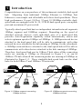
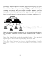
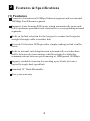
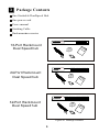
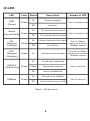
Quick Installation Guide
for 16/24/32 ports
Dual Speed Hub
ADH16SB
ADH24SB
ADH32SB
FCC COMPLIANCE STATEMENT
This equipment generates and uses radio frequency energy and if not
installed and used properly, that is, in strict accordance with the
instructions provided with the equipment, may cause interference to
radio and TV reception. The equipment has been tested and found to
comply with the limits for a Class B computing device in accordance
with the specifications in Subpart B of Part 15 of FCC rules, which are
designed to provide reasonable protection against such interference in
a commercial environment. However, there is no guarantee that
interference will not occur in a particular installation.
If you suspect this equipment is causing interference, turn your hub on
and off while your radio or TV is showing interference to determine
the source of the interference.
You can try to correct the interference by one or more of the following
measures:
1. Reorient the receiving radio or TV antenna where this may be done
safely.
2. To the extent possible, relocate the radio, TV or the other receiver
away
from the equipment.
3. Plug the computer which has the equipment installed into a different
power
outlet so that equipment and the receiver are on different branch
circuits.
If necessary, you should consult the place of purchase or an
experienced radio/ television technician for additional suggestion.
CAUTION : The phone jack cannot be connected to telephone system.
Contents
Chapter 1 Introduction ....................................1
Chapter 2 Features & Specifications .................3
Chapter 3 Package Contents .............................5
Chapter 4 Physical Description ........................6
Chapter 5 Installation ......................................9
Chapter 6 Trouble-shooting .............................12
11 Introduction
Congratulations on your purchase of this rackmount stackable dual-speed
hub. Migrating from traditional 10Mbps Ethernet to 100Mbps Fast
Ethernet is now simple and affordable with these dual-speed hubs. These
high performance 16-port, 24-Port, 32-port 10/100Mbps stackable dualspeed hubs are equipped with 16, 24, 32 RJ45 dual-speed ports, one uplink
port and one internal 2-port switch.
Typically a dual-speed hub has two independent internal network segments:
10Mbps segment and 100Mbps segment. Depending on the speed of
attached network devices, each individual port of a dual-speed hub
provides Auto-Negotiation capability which automatically senses and
selects optimum speed at 10Mbps or 100Mbps. A 10Mbps network device
attached to the dual-speed hub will be able to communicate with other
network devices attached to the hub running at 10Mbps. On the other hand,
a 100Mbps network device attached to the dual-speed hub will be able to
communicate with other devices attached to the hub running at 100Mbps.
Therefore, dual-speed hub can be 10Base-T hub when all the connecting
nodes are running at 10Mbps as illustrated in Figure 1-1, or can be
100Base-TX hub when all the connecting nodes are running at 100Mbps as
illustrated in Figure 1-2. These stackable dual-speed hubs are the ideal
hubs for both 10Base-T and 100Base-TX networks.
10Mbps
10M
COL
% 1
UTIL
3
5
10
100M
30 50+ COL
% 1
3
5
10
Power
2
3
4
5
6
7
8
9
2
3
4
9
10
11
12
17
18
10Mbps
19
20
24-Port10/100MbpsDual Speed Stackable Ethernet Hub
with Internal Switch
10M
COL
30 50+
UTIL
Switch
1
100Mbps
1
24-Port10/100MbpsDual Speed Stackable Ethernet Hub
with Internal Switch
10 11 12 13 14 15 16 17 18 19 20 21 22 23 24
% 1
UTIL
100M
Switch
LNK/ACT
Power
5
6
7
8
13
14
15
16
21
22
23
24
10Mbps
5
10
100M
30 50+ COL
% 1
3
5
10
100Mbps
1
2
3
4
9
10
11
12
17
18
19
20
5
6
7
8
13
14
15
16
21
22
23
24
30 50+
UTIL
LNK/ACT
2
3
4
5
6
7
8
9
10 11 12 13 14 15 16 17 18 19 20 21 22 23 24
Uplink
10Mbps
10Mbps
3
100M
1
100Mbps
10Mbps
100Mbps
Figure 1-1 10Mbps segment connecting
10Mbps devices
Uplink
100Mbps
100Mbps
Figure 1-2 100Mbps segment connecting
100Mbps devices
1
Dual-Speed hub with internal switching function automatically switches
data traffic between devices running at different speed, which allows
communications between ports running at 10Mbps and ports running at
100Mbps. Dual-Speed hub with internal switching function can save
money by eliminate the need to purchase expensive Switches for users
with mixed speed network environment. The connection of the DualSpeed hub with internal switching function is illustrated as in Figure 1-3:
Internal
Switch
10Mbps
24-Port10/100MbpsDual Speed Stackable Ethernet Hub
with Internal Switch
10M
COL
% 1
UTIL
3
5
10
100M
30 50+ COL
% 1
3
5
10
100Mbps
1
2
3
4
9
10
11
12
17
18
19
20
5
6
7
8
13
14
15
16
21
22
23
24
30 50+
UTIL
100M
Switch
Power
LNK/ACT
1
2
3
4
5
6
7
8
9
10 11 12 13 14 15 16 17 18 19 20 21 22 23 24
Uplink
100Mbps
10Mbps
100Mbps
10Mbps
Figure 1-3 Internal switch links 10Mbps and
100Mbps segments
When you ready to expand your network, the Uplink port provides an easy
way to connect to another hub with regular straight-through Category 5
cable
These Dual Speed Hubs provide the stackable feature. They can stack
together up to 6 hubs to form a logically Big dual-speed Hub.
These Dual-Speed hubs can be set up as stand-alone units or it can be
mounted on a standard 19" rack (rack mounting kits are included with the
unit).
2
22 Features & Specifications
(1) Features
Consists of one internal 10Mbps Ethernet segment and one internal
100Mbps Fast Ethernet segment.
Supports Auto-Sensing RJ45 ports which automatically sense and
select optimum speed and route data traffic to corresponding internal
segments.
Built-in Uplink selection for the last port to connect with regular
straight-through cable to another hub.
Network Utilization LEDs provides simple reading on hub s traffic
status.
Built-in internal switching function automatically switches data
traffic between devices running at different speed establishes
communications between ports running at 10Mbps and 100Mbps.
Support stackable function for stacking up to 6 hubs to form a
logically single dual-speed hub.
Standard 19" Rack Mountable
Two-year warranty
3
(2) Specifications
Standards : IEEE 802.3 & 802.3u
10/100Mbps Ports : RJ45 x 16 (16-Port Rackmount Dual Speed Hub) or
RJ45 x 24 (24-Port Rackmount Dual Speed Hub) or
RJ45 x 32 (32-Port Rackmount Dual Speed Hub)
Hub LEDs : Power, Internal Switch
Segment LEDs : Collision, Utilization
Port LEDs : Speed Status(10 or 100), Link/Activity Status
Internal Switch : 1K MAC Address Table
256KB Buffer Memory
Dimensions : 17.3 x 7.9 x 1.75 in./440 x 201 x 45 mm
Weight : 5.1 lb./2.3kg
Power : 100-240V AC, 50-60Hz internal full-range switching power
Operating Temperature : 32-1310F (0-550C)
Operating Humidity : 10-95% (Noncondensing)
Emission : FCC Class B & CE
4
33 Package Contents
One Stackable Dual
- Speed Hub
One power cord
User s manual
Stacking Cable
Rackmountaccessories
% 1
10M
COL
5
10
4
5
30 50+
UTIL
% 1
100M
COL
5
10
30 50+
UTIL
16-Port10/100Mbps
1
2
3
4
5
6
7
8
9
10
11
12
13
14
15
16
Uplink
Switch
100M
Power
LNK
ACT
1
2
3
6
7
8
9
10
11 12 13 14 15 16
Dual Speed
Stackable Ethernet Hub
16-Port Rackmount
Dual Speed hub
% 1
10M
COL
5
10
4
5
30 50+
UTIL
% 1
100M
COL
5
10
30 50+
UTIL
24-Port10/100Mbps
1
2
3
4
5
6
7
8
9
10
11
12
13
14
15
16
17
18
19
20
21
22
23
24
100M
LNK
ACT
Switch
100M
Power
LNK
ACT
1
2
3
6
7
8
13 14 15 16 17 18 19 20
9
10
Uplink
11 12
Dual Speed
Stackable Ethernet Hub
21 22 23 24
24-Port Rackmount
Dual Speed hub
% 1
10M
COL
5
10
30 50+
UTIL
% 1
100M
COL
5
10
30 50+
UTIL
32-Port10/100Mbps
1
2
3
4
5
6
7
8
9
10
11
12
13
14
15
16
17
18
19
20
21
22
23
24
25
26
27
28
29
30
31
32
100M
LNK
ACT
Switch
100M
Power
LNK
ACT
1
2
3
4
17 18 19 20
5
6
7
8
9
10
Uplink
11 12 13 14 15 16
21 22 23 24 25 26 27 28 29 30 31 32
Dual Speed
Stackable Ethernet Hub
32-Port Rackmount
Dual Speed hub
Figure 3-1 Package contents
5
44 Physical Description
(1) Panel
LED Panel
% 1
10M
COL
5
10
30 50+
UTIL
% 1
100M
COL
5
10
30 50+
UTIL
Uplink Port
RJ45 connectors
16-Port10/100Mbps
1
2
3
4
5
6
7
8
9
10
11
12
13
14
15
16
Uplink
Switch
100M
Power
LNK
ACT
1
2
3
4
5
6
7
8
9
10
11 12 13 14 15 16
Dual Speed
Stackable Ethernet Hub
IN
OUT
16-Port Rackmount
Dual Speed Hub
Stacking ports
100M Col. and Util. LED
10M Col. and Util. LED
% 1
10M
COL
Switch
100M
Power
LNK
ACT
5
10
30 50+
UTIL
1
2
3
4
5
6
7
% 1
100M
COL
8
5
10
30 50+
16-Port10/100Mbps
UTIL
9
10
Link/Activity
LED
Internal Switch LED
Power LED
LED Panel
% 1
10M
COL
5
10
4
5
30 50+
UTIL
% 1
100M
COL
5
10
30 50+
UTIL
100M
LED
Dual Speed
Stackable Ethernet Hub
11 12 13 14 15 16
Uplink Port
RJ45 connectors
24-Port10/100Mbps
1
2
3
4
5
6
7
8
9
10
11
12
13
14
15
16
17
18
19
20
21
22
23
24
100M
LNK
ACT
Switch
100M
Power
LNK
ACT
1
2
3
6
7
8
9
13 14 15 16 17 18 19 20
10
Uplink
11 12
Dual Speed
Stackable Ethernet Hub
21 22 23 24
IN
OUT
24-Port Rackmount
Dual Speed Hub
Stacking ports
10M Col. and Util. LED
% 1
10M
COL
5
10
30 50+
UTIL
% 1
100M
COL
5
10
30 50+
UTIL
100M Col. and Util. LED
24-Port10/100Mbps
100M
LNK
ACT
Switch
100M
Power
LNK
ACT
1
2
3
4
5
6
7
8
13 14 15 16 17 18 19 20
9
10
11 12
21 22 23 24
Internal Switch LED
Power LED
Dual Speed
Stackable Ethernet Hub
Link/Activity
LED
Figure 4-1 Panel description
6
100M
LED
LED Panel
% 1
10M
COL
5
10
4
5
30 50+
UTIL
% 1
100M
COL
5
10
Uplink Port
RJ45 connectors
1
2
3
4
5
6
7
8
9
10
11
12
13
14
15
16
17
18
19
20
21
22
23
24
25
26
27
28
29
30
31
32
30 50+
UTIL
100M
LNK
ACT
Switch
100M
Power
LNK
ACT
1
2
3
6
7
8
9
10
Uplink
11 12 13 14 15 16
32-Port 10/100Mbps
17 18 19 20
21 22 23 24 25 26 27 28 29 30 31 32
IN
OUT
32-Port Rackmount
Dual Speed Hub
Stacking ports
10M Col. and Util. LED
% 1
10M
COL
5
10
30 50+
UTIL
% 1
100M
COL
5
10
30 50+
UTIL
100M Col. and Util. LED
32-Port10/100Mbps
100M
LNK
ACT
Switch
100M
Power
LNK
ACT
1
2
3
4
17 18 19 20
5
6
7
8
9
10
11 12 13 14 15 16
21 22 23 24 25 26 27 28 29 30 31 32
Internal Switch LED
Power LED
100M
LED
Dual Speed
Stackable Ethernet Hub
Link/Activity
LED
Figure 4-1 Panel description (cont.)
7
(2) LED
LED
Color
PWR
(Power)
Green
Switch
Green
(Internal Switch)
COL
(Segment
Collision)
Yellow
UTIL.
(Segment
Utilization)
Green
Description
Lit
Power is supplied
Off
No power
Number of LED
One for the whole Hub
Lit
The internal switch is active
Off
The internal switch is inactive
Lit
Collision detected in this segment
One for the whole Hub
Off
LNK/ACT
Green
(Link/Activity)
100Mbps
Status
No Collision
Lit
Indicate network utilization
Lit
A valid link is established
Flash
Data packets received
Off
No link is established
Lit
This port run at 100Mbps
Off
Not connected or run at 10M
Green
One for 10Mbps
segment and one for
100Mbps segment
One set for 10Mbps
segment and one set for
100Mbps segment
One for each port
One for each port
Table 4-1 LED description
8
55 Installation
1. Operating Environment
These Dual Speed Hubs must be installed and operated within the limits
of specified operating temperature and humidity (see previous section
under Specifications). Do not place objects on top of the unit. Do not
obstruct any vents at the sides of the unit. Do not position the hub near
any heating source such as heater, radiator, or direct exposure to sun.
Prevent entering of water and moisture into the unit. If necessary, use
dehumidifier to reduce humidity.
2. Connecting to network devices
Connect one end of the network cable to any of the RJ45 ports on the
front panel, and connect the other end of the network cable to the RJ45
port of the network device. The network cables must comply with
EIA/TIA 568 specifications and Category 5 standard for 100Mbps data
rate or minimum Category 3 for 10Mbps data rate. Maximum length
between the hub and any network devices is 100 meters (300ft). Once
the network cable is connected on both ends and the attached network
devices are powered on, the green Link Status LED should be lit. If the
connected network devices are running at 100Mbps, the green Speed
LED (100M) should also be lit.
Dual Speed Hub
% 1
10M
COL
5
10
4
5
30 50+
UTIL
% 1
100M
COL
5
UTIL
10
30 50+
24-Port10/100Mbps
1
2
3
4
5
6
7
8
9
10
11
12
100M
LNK
ACT
Switch
100M
Power
LNK
ACT
1
2
3
6
7
8
13 14 15 16 17 18 19 20
9
10
Uplink
11 12
21 22 23 24
Dual Speed
Stackable Ethernet Hub
13
14
15
16
17
18
19
20
21
22
23
24
Category 5
EIA/TIA 568
UTP Cable
Network
Adapter
10/100 FAST ETHERNET CARD
FCC ID :
RTL8139
100m
Figure 5-1 Connect the hub and network device
3. Uplink to Another Hub
Use the uplink port (the last port) to connect to another hub as illustrated
in Figure 5-2.
Connecting cable must comply with EIA/TIA 568
specifications and Category 5 (100Mbps) standards to connect the hubs.
The Uplink port of the Dual-Speed hub supports Auto-Sensing function
which will automatically sense the speed of the connected hub and
operates at either 100Mbps or 10Mbps speed. If the connected hub is
another Dual-Speed hub or 100Base-TX hub, the transmission speed
between the two hubs will be set at 100Mbps and the green Speed (100M)
LED should be lit. The maximum length of the cable should not exceed 5
meters (15ft) when connecting two hubs running at 100Mbps and 100
meters (300ft) when connecting two hubs running at 10Mbps.
9
Uplink Port
Uplink
Dual Speed Hub
% 1
10M
COL
5
10
4
5
30 50+
UTIL
% 1
100M
COL
5
10
30 50+
24-Port10/100Mbps
UTIL
1
2
3
4
5
6
7
8
9
10
11
12
13
14
15
16
17
18
19
20
21
22
23
24
100M
LNK
ACT
Switch
100M
Power
LNK
ACT
1
2
3
6
7
8
13 14 15 16 17 18 19 20
9
10
Uplink
11 12
Dual Speed
Stackable Ethernet Hub
21 22 23 24
Uplink Port
% 1
10M
COL
5
10
4
5
30 50+
UTIL
% 1
100M
COL
5
UTIL
10
30 50+
24-Port10/100Mbps
1
2
3
4
5
6
7
8
9
10
11
12
13
14
15
16
17
18
19
20
21
22
23
24
100M
LNK
ACT
Switch
100M
Power
LNK
ACT
1
2
3
6
7
8
13 14 15 16 17 18 19 20
9
10
Uplink
11 12
21 22 23 24
Dual Speed
Stackable Ethernet Hub
Normal Port
Figure 5-2 Uplink to another hub
4. Stacking Hubs Together
These Dual Speed Hubs provide two stacking ports. Users may connect two
hubs using the supplied stacking cable. Connect one end of the stacking
cable to the IN stacking connector of the hub and the other end of the
stacking cable to another hub OUT stacking connector. You may stack up to
10 hubs. The hubs cascaded together through stacking ports are in one
collision domain and therefore considered as one logical dual speed hub.
Internal
Switch
% 1
10M
COL
5
10
4
5
30 50+
UTIL
% 1
100M
COL
5
10
30 50+
10
30 50+
UTIL
24-Port10/100Mbps
1
2
3
4
5
6
7
8
9
10
11
12
13
14
15
16
17
18
19
20
21
22
23
24
1
2
3
4
5
6
7
8
9
10
11
12
13
14
15
16
17
18
19
20
100M
1
LNK
ACT
Switch
Power
2
3
6
7
8
9
10
Uplink
11 12
Dual Speed
Stackable Ethernet Hub
100M
LNK
ACT
13 14 15 16 17 18 19 20
% 1
10M
COL
5
10
4
5
30 50+
UTIL
21 22 23 24
% 1
100M
COL
5
UTIL
24-Port10/100Mbps
100M
1
LNK
ACT
Switch
100M
Power
LNK
ACT
2
3
6
7
8
13 14 15 16 17 18 19 20
% 1
10M
COL
5
10
30 50+
UTIL
9
10
Uplink
11 12
Dual Speed
Stackable Ethernet Hub
21 22 23 24
% 1
100M
COL
5
10
30 50+
UTIL
24-Port10/100Mbps
21
22
23
24
1
2
3
4
5
6
7
8
9
10
11
12
13
14
15
16
17
18
19
20
21
1
2
3
13
14
15
100M
1
LNK
ACT
Switch
Power
2
3
4
5
6
7
8
9
10
Uplink
11 12
Dual Speed
Stackable Ethernet Hub
100M
LNK
ACT
13 14 15 16 17 18 19 20
% 1
10M
COL
5
10
UTIL
100M
1
LNK
ACT
Switch
100M
Power
LNK
ACT
2
3
4
5
6
7
% 1
5
10
4
5
30 50+
UTIL
% 1
100M
COL
8
13 14 15 16 17 18 19 20
10M
COL
21 22 23 24
10Mbps
30 50+
5
10
30 50+
UTIL
9
10
11 12
Dual Speed
Stackable Ethernet Hub
21 22 23 24
% 1
100M
COL
24-Port10/100Mbps
5
10
30 50+
UTIL
24-Port10/100Mbps
22
23
100Mbps
24
4
5
6
7
8
9
10
11
12
16
17
18
19
20
21
22
23
24
Uplink
1
2
3
4
5
6
7
8
9
10
11
12
13
14
15
16
17
18
19
20
21
22
23
24
100M
1
LNK
ACT
Switch
100M
Power
LNK
ACT
2
3
6
7
8
13 14 15 16 17 18 19 20
% 1
10M
COL
5
10
4
5
30 50+
UTIL
9
10
11 12
Uplink
Dual Speed
Stackable Ethernet Hub
21 22 23 24
% 1
100M
COL
5
UTIL
10
30 50+
24-Port10/100Mbps
1
2
3
4
5
6
7
8
9
10
11
12
13
14
15
16
17
18
19
20
21
22
23
24
100M
LNK
ACT
Switch
100M
Power
LNK
ACT
1
2
3
6
7
8
13 14 15 16 17 18 19 20
9
10
11 12
21 22 23 24
Uplink
Dual Speed
Stackable Ethernet Hub
Figure 5-3 Stack 6 hubs together
When you have two or more hubs stacked together, only one hub s internal
switch is active, the others are inactive. Such design will eliminate a Loop
in the network that might cause the whole network to malfunction.
10
5. Connecting the power
Connect the power cord to the power socket on the rear panel of the unit.
Connect the power cord to the power outlet and turn on power switch. The
green Power LED on the front panel should be lit.
IN
OUT
Figure 5-4 Connect the power cable
11
66 Trouble-shooting
1. Power LED is not lit
Check if the power cord is properly connected to the power outlet and the
hub. Make sure the power switch on the hub is turned ON. .
2. Link Status LED is not lit
Check the power switch of the network devices attached to the hub, make
sure they are turned ON.
Check the network cable, make sure it is properly connected to the hub and
the network device.
Check the network cable, make sure the cable complies with EIA/TIA 568
specification. Use straight-through Category 5 cables for 100Mbps
connection and Category 3 or higher cables for 10Mbps connection.
Check the slide switch and make sure it s in normal position when you use
the last port on the hub to connect to workstations or file servers.
3. The last port s Link Status LED is not lit when it is uplinked to
another hub
Make sure the cable is connected to the "uplink" connector.
Check the network cable, make sure it is properly connected to both hubs.
One end of the cable should be connected to uplink port while the other end
of the cable should connected to a regular port. Do not connect the cable to
both uplink ports.
Check the network cable, make sure the cable complies with EIA/TIA 568
specification. Use Category 5 cables for 100Mbps connection.
Check the network cable, make sure the maximum length does not exceed 5
meters (15ft) in 100Mbps connection and 100 meters (300ft) in 10Mbps
connection.
4. Collision LED flashes constantly
Remove all the network cables, connect the cables back one by one to
isolate the source of the collision.
Check the network cable, inferior cable quality will result in excessive
collision and error packets.
[!] Contact your dealer if problem persist.
12