1
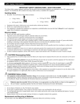
MOV101 METAL OXIDE SURGE ARRESTERS TEST SET User’s Manual (2014) Precision Diagnostic Instrument LLC Houston, Texas, USA Telephone: (+1-281-7969258) Fax: (+1-281-3929081) Web: http://www.pdinstr.com Table of Contents 1. MENTAL OXIDE SURGE ARRESTER ON-LINE DIAGNOSTICS ............................................... 3 2. MOV101 SYSTEM SPECIFICATION ...................................................................................... 7 2.1 2.2 2.3 3. MEASURING PROCEDURE AND DATA MANAGEMENT........................................................ 12 3.1 3.2 3.3 4. System Characteristics ................................................................................................................................ 7 Technical Advantages.................................................................................................................................. 8 System Specifications .................................................................................................................................. 9 Measure MOA Leakage Current ............................................................................................................. 12 System Third Harmonic Compensation .................................................................................................. 17 Data Management...................................................................................................................................... 23 MOV101 MOBILE MEASURING PROCEDURE .................................................................... 24 2 1. MENTAL OXIDE SURGE ARRESTER ON-LINE DIAGNOSTICS Surge Arresters constitute an indispensible aid to insulation conditions of the electrical power systems. Figure 2 makes this clear, where the voltages which may appear in a high-voltage power system are given in per-unit of the peak of the continuous phase-to-ground voltage ( U s ), depending on the duration of their appearance. High-voltage terminal Grading ring Insulating feet Figure 1 A two unit high-voltage arrestor Figure 2 Schematic representation of the magnitude of the voltage and over-voltage in high𝟐 voltage electrical power systems verses the duration of their appearance (1 p.u=√𝟑 𝐔𝐒 ) 3 Even through a great number of arresters which are gapped arresters made of silicon-carbide (SiC), are still in use, the arresters installed today are almost all metal-oxide (MO) arresters (MOA) without gaps. The distinctive feature of the MO resistor is its extremely non-linear voltage-current or V-I characteristics, as shown in Figure 3. The current pass through the arrester within the range of possibly applied power-frequency voltages are so small that the arrester almost behaves likes an insulator. If, however, the surge currents in kiloampere are injected into the arrestor, such as in the cases when lighting or switching overvoltage occur, then the resulting voltage across its terminals will remain low enough to protect the insulation of the associated device from effects of overvoltage. Figure 3 V-I characteristic of a typical MOA in a solidly earthed neutral 420-KVsystem Although a metal-oxide arrester (MOA) requires no ordinary maintenance, it is desirable from a utility point of view to check the condition of the surge arresters at regular time intervals. For practical and economical reasons, it is preferred that the check can be carried out without deenergizing or disconnecting the arrester, especially when high-voltage surge arresters are considered. This approach is usually referred as the on-line diagnostic approach. The most effective method for MOA on-line diagnostic is to monitor the resistive leakage current at the normal operation conditions. Figure 4 shows a lump-sum model of the MOA under the normal operation conditions, where R represents the resistance of the MO resistor and C represents the parasitic capacitance of the arrestor. 4 𝐼𝑡 𝐼𝐶 𝐼𝑅 𝐶 𝑅 Figure 4 A lump-sum model of MOA The overall leakage current flows through the arrester is the combination of two elements: the resistive leakage current I R , and the capacitive leakage current I C . The capacitive component of the leakage current is much larger than the resistive component. It IC I R I C I R Since I C is largely not affected by the arrester’s operational status, and also the fact I C I R , then measuring the total leakage current is not an effective approach for MOA on-line diagnostic. However, to extract the resistive component involves measuring the system voltage and compensating the capacitive component from the total leakage current. It is not only complicated but also sometimes inhibitive in practical. A much better approach is harmonic analysis. Due to the non-linear characteristic of MO resister, even under the normal system phase-to-ground voltage U s , there are higher order harmonic currents generated. In fact, the resistive component of the leakage current can be decomposed into the combination of the primary resistive leakage current and the higher order harmonic resistive leakage currents: I R I R1 I R 3 If assuming the system voltage does not contain any higher order harmonic components 1, and further if ignoring the fifth and higher harmonic components of the resistive leakage current since they are much smaller than the third harmonic component of the resistive leakage current, then the total leakage current could be expressed as the combination of the capacitive leakage current plus the primary and the third harmonic components of the resistive leakage current: 1 In case the system harmonic cannot be ignored, the compensation is required. The details of the system harmonic compensation are discussed in Section 0. 5 I t I C I R1 I R 3 It is clear that the third harmonic component of the total leakage current is in fact the third harmonic component of the resistive leakage current. Therefore, it is possible to obtain the third harmonic component of the resistive leakage current without monitoring the system voltage, but directly through the harmonic analysis of the total leakage current. This is called the harmonic analysis approach. The harmonic analysis approach significantly simplifies the measuring process, and makes the MOA on-line diagnostic possible in practical. The MOV101 is designed based on the harmonic analysis. 6 2. MOV101 SYSTEM SPECIFICATION 2.1 System Characteristics MOV101 Metal Oxide Surge Arresters Test System has highlighted characteristics: ON-LINE DIAGNOSTIC OF METAL OXIDE SURGE ARRESTERS COMPLYING TO IEC 60099-5 A1 “DIAGNOSTIC INDICATORS OF METAL-OXIDE SURGE ARRESTERS IN SERVICE” THIRD HARMONIC ANALYSIS OF LEAKAGE CURRENT WITH COMPENSATION AUTOMATIC TEMPERATURE COMPENSATION SOPHISTICATED ANALYSIS AND EARLY WARNING ASSISTANT EASY, FAST AND RELIABLE DIAGNOSTIC METHOD SAFE LIGHTWEIGHT EQUIPMENT A MOV101 test system contains the following sub-systems. (2) (1) (3) Item 1 2 3 Description MOV101 Tester Clamp-on Current Probe PT Secondary System Voltage Probe Table 1 Complete MOV101 System 7 2.2 Technical Advantages MOV101 system has distinguished technical advantages comparing to the traditional MOA test system. CLAMP-ON CURRENT TRANSFORMER FOR LEAKAGE CURRENT SAMPLING MOV101 uses a clamp-on current transformer for leakage current sampling. The advantage of clampon current transformer is safety and easy usability. The disadvantage of clamp-on current transformer is large impact of environment Electro-Magnetic (EM) noise on the measurement accuracy. MOV101 utilizes a special EM noise rejection approach that guarantees ±1μA measurement accuracy under the heavy EM noise environment. THIRD HARMONIC LEAKAGE CURRENT TEMPERATURE COMPENSATION MOA resistive leakage current can be formulated as function of system voltage and temperature: I R K U In which: I R is resistive leakage current U is system voltage K is a material-specific constant is a function of temperature and voltage Environment temperature has significant impact on MOA resistive leakage current. Figure 5 and Figure 6 illustrate the typical MOA resistive leakage current could change up to 50% when environment temperature changing from 20°C to 50°C. Without proper temperature compensation, it is impossible to compare the MOA resistive leakage current measurement with historical testing results. Figure 5 Typical resistive leakage current for a 75mm diameter ZnO Varistor 8 Figure 6 Typical value in leakage current region MOV101 utilizes a build-in temperature compensation mechanism to automatically normalize the measured MOA resistive leakage current to 20°C. Thus, makes the trend analysis and comparison of historical testing results possible. SYSTEM THIRD HARMONIC COMPENSATION In case there are large third harmonic presented in the system, the measured third harmonic is summation of system third harmonic and MOA third harmonic resistive leakage current. For 110KV and above system, system third harmonic is usually small and negligible (< 0.2% typically). If system third harmonic is more than 2%, the compensation is required to eliminate the system harmonic impact. MOV101 provides a simple and effective system third harmonic compensation approach by measuring the system third harmonic through PT secondary. 2.3 System Specifications MEASUREMENT PERFORMED True rms of the total current. Peak value of the total current True rms of the third harmonic. Temperature. MEASUREMENTS RANGES Total current range: < 20mA Third harmonic range: < 20mA Automatic range selection. 9 ACCURACY Total current accuracy: ±1 μA Third harmonic accuracy: ±1 μA INSENSITIVITY TO EXTERNAL FIELDS Electric field: < 10 kV/m. Uniform magnetic field: < 50 μT. CURRENT CLAMP-ON TRANSFORMER Jaw Opening: 2.55” (57mm) max Max Conductor Size: 2.05” (52mm) Max Bus Bar Size: One 1.95 x 0.19” (50 x 5mm) VOLTAGE MEASURING PROBE Usage: connect to PT secondary for measuring the third harmonic of the system voltage Length: 10ft (3m) Nominal voltage: 100 V phase to phase (57.8 V phase to neutral). Maximum voltage: 200 V phase to phase. CALIBRATION Internal self-calibrated. WEIGHT AND DIMENSIONS Measuring Instruments: Diecast Enclosure Weight: 1.0 lbs (0.45kg) Dimensions: 7.0 x 4.3 x 1.3” (178 x 110 x 32mm) Clamp-on Current Transformer: Weight: 1.21 lbs (0.55kg) Dimensions: 4.37 x 8.59 x 1.77” (111 x 216 x 45mm) Carry Case: Plastic carry case holds: the clamp-on transformer, the voltage probe, and the measuring instrument. Dimension: 18.7 x 14.8 x 7” (475 x 376 x 178 mm) Weight with all the components: 9 lbs (4.08kg) ENVIRONMENTAL 10 Operating temperature: -40°C - 85°C Storage: 0°C to 70°C Relative humidity: 10 - 80% without condensing 11 3. MEASURING PROCEDURE AND DATA MANAGEMENT 3.1 Measure MOA Leakage Current Step 1 Procedure Connect MOV101 to PC through USB USB 12 Step 2 Procedure Clamp the clamp-on current transformer around MOA ground connections, such as around the output of surge counter and etc. Clamp ON 13 Step 3 Procedure Click “Go” button to start measuring MOA leakage current. Click “Go” Button The measured third harmonic RMS is temperature compensated and normalized to 20 °C. 14 Step 4 Procedure MOA leakage current displayed. Leakage Current Waveform Leakage Current Spectrum 15 Step 5 Procedure Save the measuring results. Click on “Save” button. Click “Save” Button Enter the location and other information in the promoted saving window. Select if wish to save waveform 16 3.2 System Third Harmonic Compensation To compensate the system third harmonic, use the voltage probe to measure the system third harmonic from PT secondary, and apply the compensation. Step 1 Procedure Connect MOV101 to PC through USB USB 17 Step 2 Procedure Select “Compensate” tab, and then select the MOA test result that requires system third harmonic compensation. Note: To ensure the validity of system third harmonic compensation, the compensation only applied to the most recent MOA test results (pass 24 hours). Therefore, only the most recent MOA test results (pass 24 hours) MOA test results are displayed in selection window. Select “Analysis” Tab Select MOA test result that requires compensation Uncompensated test results 18 Step 2 Procedure Connect the voltage probe to PT secondary of the corresponding MOA selected to be compensated. Connect to PT Secondary 19 Step 3 Procedure Click “Go” button to start measuring system third harmonic. Click “Go” Button 20 Step 4 Procedure Apply system third harmonic compensation and display the compensated results. Note: MOV101 will automatic check the validity of system third harmonic measurement, and apply the compensation. If found invalid, the compensation will not be applied. System Voltage Waveform Compensated MOA third harmonic RMS 21 Step 5 Procedure Save the measuring results. Click on “Save” button. Click “Save” Button 22 3.3 Data Management Data management plots historical test results, and make it easy to visualize the potential failure. Select “Compensate” Tab Select MOA to display test results Move mouse to data point, and left click to show value Select test results to plot 23 4. MOV101 MOBILE MEASURING PROCEDURE Step 1 Procedure Connect MOV101 to Android mobile device through USB + OTG adapter. Lunch MOV101 mobile app. USB OTG Adapter 24 Step 2 Procedure Clamp the clamp-on current transformer around MOA ground connections, such as around the output of surge counter and etc. Clamp ON 25 Step 3 Procedure If system third harmonic compensation is required, connect the voltage probe to PT (optional) secondary of the corresponding MOA selected to be compensated. Connect to PT Secondary 26 Step 4 Procedure Click “Go” button to start measuring MOA leakage current. Click “Go” Button The measured third harmonic RMS is temperature compensated and normalized to 20 °C. 27 Step 5 Procedure View full measurement report and waveform. 28