1
Institute of Machine Learning and Robotic Lab
University of Stuttgart
Universitätsstraße 38
D–70569 Stuttgart
Diploma Thesis Nr. 3494
Two-Wheeled-Racer
Marcel Dreher
Course of Study:
Software Engineering
Examiner:
Prof. Dr. rer. nat Marc Toussaint
Supervisor:
Prof. Dr. rer. nat Marc Toussaint
Commenced:
July 7, 2013
Completed:
December 6, 2013
CR-Classification:
B.7.1
Abstract
. . . The following document describes the process, problems and solutions of the project
"Two-Wheeled-Racer". The project focuses on constructing the robot and providing the core
communication principles in addition with basic balancing control.
The single-board computer Odroid-X2+ is used as a brain for the Racer to process the data
received from an accelerometer and a gyroscope and solve the inclination angle problem.
To reduce the noise of the sensors the data are filtered and combined with the help of a
complementary filter. A PID control algorithm is running on the Odroid-X2+ to react on the
inclination angle calculated from the sensor data and to prevent the robot from falling over.
Two 30:1 gear motors controlled by a MD25 H bridge dual motor drive are used as actuators.
The data are transferred among the hardware components with the help of the I2 C protocol.
3
Contents
1
Introduction
1.1 Motivation . . . . . . . . . . . . . . . . . . . . . . . . . . . . . . . . . . . . . .
1.2 Outline . . . . . . . . . . . . . . . . . . . . . . . . . . . . . . . . . . . . . . . .
2
Background
2.1 I2 C . . . . . . . . . . . .
2.2 SPI . . . . . . . . . . . .
2.3 Proportional Controller
2.4 Integral Controller . . .
2.5 Derivative Element . . .
2.6 PID-Controller . . . . .
2.7 Complementary Filter .
2.8 termios . . . . . . . . .
2.9 Singleton Pattern . . . .
3
.
.
.
.
.
.
.
.
.
.
.
.
.
.
.
.
.
.
.
.
.
.
.
.
.
.
.
Components
3.1 USB-ISS . . . . . . . . . . . .
3.2 MD25 - Dual Motor Drive . .
3.3 MPU-9150 . . . . . . . . . . .
3.4 Odroid-X2+ . . . . . . . . . .
3.5 TopFuel LiPo ECO-X 5000 3S
3.6 EMG30 . . . . . . . . . . . .
3.7 Assembly . . . . . . . . . . .
.
.
.
.
.
.
.
.
.
.
.
.
.
.
.
.
.
.
.
.
.
.
.
.
.
.
.
.
.
.
.
.
.
.
.
.
.
.
.
.
.
.
.
.
.
.
.
.
.
.
.
.
.
.
.
.
.
.
.
.
.
.
.
.
.
.
.
.
.
.
.
.
.
.
.
.
.
.
.
.
.
.
.
.
.
.
.
.
.
.
.
.
.
.
.
.
.
.
.
.
.
.
.
.
.
.
.
.
.
.
.
.
.
.
.
.
.
.
.
.
.
.
.
.
.
.
.
.
.
.
.
.
.
.
.
.
.
.
.
.
.
.
.
.
.
.
.
.
.
.
.
.
.
.
.
.
.
.
.
.
.
.
.
.
.
.
.
.
.
.
.
.
.
.
.
.
.
.
.
.
.
.
.
.
.
.
.
.
.
.
.
.
.
.
.
.
.
.
.
.
.
.
.
.
.
.
.
.
.
.
.
.
.
.
.
.
.
.
.
.
.
.
.
.
.
.
.
.
.
.
.
.
.
.
.
.
.
.
.
.
.
.
.
.
.
.
.
.
.
.
.
.
.
.
.
.
.
.
.
.
.
.
.
.
.
.
.
.
.
.
.
.
.
.
.
.
.
.
.
.
.
.
.
.
.
.
.
.
.
.
.
.
.
.
.
.
.
.
.
.
.
.
.
.
.
.
.
.
.
.
.
.
.
.
.
.
.
.
.
.
.
.
.
.
.
.
.
.
.
.
.
.
.
.
.
.
.
.
.
.
.
.
.
.
.
.
.
.
.
.
.
.
.
.
.
.
.
.
.
.
.
.
.
.
.
.
.
.
.
.
.
.
.
.
.
.
.
.
.
.
.
.
.
.
.
.
.
.
.
.
.
.
.
.
.
.
.
.
.
.
.
.
.
.
.
.
.
.
.
.
.
.
.
.
.
.
.
.
.
.
.
.
.
.
.
.
.
.
.
.
.
.
9
9
9
.
.
.
.
.
.
.
.
.
11
11
17
21
22
22
23
23
24
24
.
.
.
.
.
.
.
25
25
26
27
29
30
30
31
4
Software
33
4.1 Overview . . . . . . . . . . . . . . . . . . . . . . . . . . . . . . . . . . . . . . . 33
4.2 Software Architecture . . . . . . . . . . . . . . . . . . . . . . . . . . . . . . . . 34
4.3 Procedure . . . . . . . . . . . . . . . . . . . . . . . . . . . . . . . . . . . . . . . 35
5
Project
5.1 Initial Situation . . . . . . . . . . . . . . . . . . . . . . . . . . .
5.2 Planing Phase . . . . . . . . . . . . . . . . . . . . . . . . . . . .
5.3 Interaction with the MD25 via the USB-ISS . . . . . . . . . . .
5.4 Construction of the Racer and installing Ubuntu on the Odroid
5.5 Request Data from the IMU . . . . . . . . . . . . . . . . . . . .
5.6 Connected all Devices to the same I2 C Bus . . . . . . . . . . .
5.7 Put together the Two-Wheeled-Racer . . . . . . . . . . . . . . .
.
.
.
.
.
.
.
.
.
.
.
.
.
.
.
.
.
.
.
.
.
.
.
.
.
.
.
.
.
.
.
.
.
.
.
.
.
.
.
.
.
.
.
.
.
.
.
.
.
.
.
.
.
.
.
.
.
.
.
.
.
.
.
37
37
37
38
39
40
42
42
5
5.8
5.9
5.10
5.11
Calculate the Inclination
Remove the Angle Drift
PID Controller Setting .
Result . . . . . . . . . .
Angle
. . . .
. . . .
. . . .
.
.
.
.
.
.
.
.
.
.
.
.
.
.
.
.
.
.
.
.
.
.
.
.
.
.
.
.
.
.
.
.
.
.
.
.
.
.
.
.
.
.
.
.
.
.
.
.
.
.
.
.
.
.
.
.
.
.
.
.
.
.
.
.
.
.
.
.
.
.
.
.
.
.
.
.
.
.
.
.
.
.
.
.
.
.
.
.
.
.
.
.
.
.
.
.
.
.
.
.
.
.
.
.
.
.
.
.
43
44
47
48
6
Comparison to other solutions
49
6.1 Self-Balancing Two-Wheeled Robot . . . . . . . . . . . . . . . . . . . . . . . . . 49
6.2 Zilog ZNEO based Self-Balancing Robot . . . . . . . . . . . . . . . . . . . . . . 51
7
Conclusion
55
7.1 Summary . . . . . . . . . . . . . . . . . . . . . . . . . . . . . . . . . . . . . . . 55
7.2 Future Work . . . . . . . . . . . . . . . . . . . . . . . . . . . . . . . . . . . . . 55
Bibliography
6
57
List of Figures
2.1
2.2
2.3
2.4
2.5
2.6
2.7
2.8
2.9
2.10
2.11
2.12
2.13
2.14
2.15
2.16
2.17
Data transfer: the first bit is a logical 1 and the second bit a logical 0 . . . .
Start signal . . . . . . . . . . . . . . . . . . . . . . . . . . . . . . . . . . . . .
Stop signal . . . . . . . . . . . . . . . . . . . . . . . . . . . . . . . . . . . . .
Transmission of the byte 10110001 and acknowledgement with ACK . . . . .
7-bit-address + R/W bit . . . . . . . . . . . . . . . . . . . . . . . . . . . . . .
The structure of the two bytes containing the 10-bit-address . . . . . . . . . .
Sequence of requesting or transmitting data . . . . . . . . . . . . . . . . . . .
Sequence of combined transmission with the help of the repeated start signal
Multi-master conflict avoiding . . . . . . . . . . . . . . . . . . . . . . . . . . .
Data transfer among two shift registers . . . . . . . . . . . . . . . . . . . . . .
SPI mode 0 . . . . . . . . . . . . . . . . . . . . . . . . . . . . . . . . . . . . .
SPI mode 1 . . . . . . . . . . . . . . . . . . . . . . . . . . . . . . . . . . . . .
SPI mode 2 . . . . . . . . . . . . . . . . . . . . . . . . . . . . . . . . . . . . .
SPI mode 3 . . . . . . . . . . . . . . . . . . . . . . . . . . . . . . . . . . . . .
3-Wired-Master-Slave . . . . . . . . . . . . . . . . . . . . . . . . . . . . . . .
4-Wire-Single-Master-Multi-Slave . . . . . . . . . . . . . . . . . . . . . . . . .
Daisy-Chain . . . . . . . . . . . . . . . . . . . . . . . . . . . . . . . . . . . . .
.
.
.
.
.
.
.
.
.
.
.
.
.
.
.
.
.
12
13
13
14
14
15
15
15
16
18
18
19
19
19
20
21
21
3.1
3.2
3.3
3.4
3.5
3.6
3.7
USB-ISS . . . . . . . . . . . . .
MD25 . . . . . . . . . . . . . .
MPU-9150 . . . . . . . . . . . .
Odroid-X2 . . . . . . . . . . . .
Lithium-Polymer-Accumulator
EMG30 . . . . . . . . . . . . .
Two-Wheeled-Racer . . . . . .
.
.
.
.
.
.
.
25
26
28
29
30
31
31
4.1
Layered architecture . . . . . . . . . . . . . . . . . . . . . . . . . . . . . . . . . 33
5.1
5.2
5.3
5.4
5.5
5.6
5.7
5.8
Sketch of the Racer . . . . . . . . . . . . . . . . . . . .
Sketch of the Racer with components . . . . . . . . . .
Raw data of the accelerometer and the gyroscope . . .
Coordinate system of the IMU . . . . . . . . . . . . .
Angle between the the xy-plane and the gravity vector
Angle calculated by the gyroscope data . . . . . . . .
Accelerometer data in x-direction . . . . . . . . . . . .
Complementary filter . . . . . . . . . . . . . . . . . . .
.
.
.
.
.
.
.
.
.
.
.
.
.
.
.
.
.
.
.
.
.
.
.
.
.
.
.
.
.
.
.
.
.
.
.
.
.
.
.
.
.
.
.
.
.
.
.
.
.
.
.
.
.
.
.
.
.
.
.
.
.
.
.
.
.
.
.
.
.
.
.
.
.
.
.
.
.
.
.
.
.
.
.
.
.
.
.
.
.
.
.
.
.
.
.
.
.
.
.
.
.
.
.
.
.
.
.
.
.
.
.
.
.
.
.
.
.
.
.
.
.
.
.
.
.
.
.
.
.
.
.
.
.
.
.
.
.
.
.
.
.
.
.
.
.
.
.
.
.
.
.
.
.
.
.
.
.
.
.
.
.
.
.
.
.
.
.
.
.
.
.
.
.
.
.
.
.
.
.
.
.
.
.
.
.
.
.
.
.
.
.
.
.
.
.
.
.
.
.
.
.
.
.
.
.
.
.
.
.
.
.
.
.
.
.
.
.
.
.
.
.
.
.
.
.
.
.
.
.
.
.
.
.
.
.
.
.
.
.
.
.
.
.
.
.
.
.
.
.
.
.
.
.
.
.
.
.
.
.
.
.
.
.
.
.
.
.
.
.
.
.
.
.
.
.
.
.
.
.
.
.
.
.
.
.
.
.
.
.
.
.
.
.
.
37
39
41
43
44
45
46
46
7
1 Introduction
The goal of the project is to construct a robot balancing on two wheels similar to a Segway
but much smaller. The project is separated into two parts: the construction of the Racer and
the creation of a controller algorithm. In the first part of the project the focus lies on the
hardware. The goal is to control the motors, read out the sensor data, handle the request and
transmission of data via a data bus and finally build up the Racer. Based on the progress in
the first part of the project, the second part is focuses on processing the received data and the
development of a controller to prevent the robot from falling over.
To accomplish this task, sensors are needed which can determine the current position and
inclination, therefore an inertial measurement unit(IMU) is mounted on the robot. The IMU
contains an accelerometer that measures the acceleration in x-,y-,z-direction and a gyroscope
that measures the angle velocity. The data provided from the two sensors are used to calculate
the inclination angle relative to the balancing point of the robot.
A PID control algorithm processes the calculated inclination angle and regulates the motors of
the Racer based on the inclination angle to prevent the robot from falling over.
The Racer should be easily expandable, hence an Odroid-X2+ , fully-fledged single board
computer, is used. This computer is the brain of the robot and uses a Linux operating system.
All information are collected and processed there.
To request or transmit data to external devices an I2 C bus is used. The I2 C bus also provides
the ability to upgrade the robot easily because components that support the I2 C protocol can
be attached to the bus with minimum effort.
1.1 Motivation
Studying sometimes can be very theoretical, and the practical relevance or a platform to
test new solutions is missing. For this purpose the Two-Wheeled-Racer project shall provide
a platform to enable students to learn and solidify their knowledge by using the Racer as
demonstration tool or to test their own ideas.
1.2 Outline
This document consists of seven chapters starting with the introduction. The second chapter
Background provides a background knowledge about the used technology. It starts with the
explanation of commonly used serial bus, the SPI and I2 C bus, followed by a description of
the PID controller and its components. The chapter also provides a short description of the
9
1 Introduction
complementary filter, the termios library and the singleton pattern.
The third chapter Components gives an overview of used hardware and the specific tasks in
the robot.
The fourth chapter Software describes the architecture and the procedure of the software.
The fifth chapter Project describes the process, problems and solutions of the Two-WheeledRacer project. It begins with the initial situation and ends with the result of the project.
In the sixth chapter Comparison to other solutions two other approaches of a two-wheeledbalancing-robot are presented and short comparisons to the solution of the Two-Wheeled-Racer
are given.
The last chapter Conclusion gives a short summary and describes future work.
10
2 Background
2.1 I2 C
I2 C is a synchronous serial bus and stands for inter-integrated-circuit[spi08][NXP12][Sem][Inv].
It is based on two wires: the serial data wire (SDA) and the serial clock wire (SCL). Both
lines are bi-directional, which means each device connected to the bus can request or send
data. Any device connected to the I2 C bus is attached additionally to a supply voltage and
the ground. To ensure that only the requesting device receives the data, all devices possess a
unique address.
A device connected to the I2 C bus can either act as a master or as a slave device. The master
device generates the required clock signal, therefore the I2 C bus must have at least one master
device connected. It is possible to attach multiple devices which can act as a master to the
I2 C bus, a so called multi-master-bus. But in this case it must be guaranteed that only one
master is active at one time or rather act as a master. To accomplish this, the I2 C protocol
provides an arbitration solution.
A device connected to the I2 C bus can either act as a receiver or as a sender, regardless of its
role as a master or a slave device, but the master device always initiates the data transfer.
If the bus is free, that means no data transmission is in progress, the SDA and the SCL wires
will be at HIGH level. Each clock pulse is going to transfer one bit.
2.1.1 Speed
The I2 C bus offers multiple transfer rates:
• Low Speed Mode 10 kBit/s
• Standard Mode 100 kBit/s
• Fast Mode 400 kBit/s
• High Speed Mode 3,4 MBit/s
Clock Synchronization
If the receiver device requires more time to process the received data than the sender device
needs to transfer data, the receiver is able to force the sender into a wait state. The sender
device pauses as long as it takes the receiver to processes the data and get ready for the next
transmission. To accomplish this, the receiver holds the SCL wire at LOW level. The transfer
11
2 Background
cannot continue until the device frees the SCL wire again. A synchronized clock is generated:
The LOW period determined by the device with the longest clock LOW phase and the HIGH
period determined by the device with the shortest clock HIGH phase.
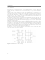
2.1.2 Data Validity
To send valid data bits, the applied voltage of the SDA wire must not be changed while the
applied voltage of the SCL wire is at the HIGH level. Otherwise the signal will be interpreted
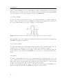
as a control signal. Figure 2.1 shows an example of a data transfer.
Figure 2.1: Data transfer: the first bit is a logical 1 and the second bit a logical 0
The transmitted bytes are transferred with high-bit-first, that means the Most Significant
Bit(MSB) is the first bit transferred.
2.1.3 Control Signals
To control and initiate the communication among devices and to guarantee that only one
sending and one receiving device is active at one time, control signals are required.
Control signals can be identified by the change of the voltage level of the SDA wire while the
applied voltage of the SCL wire is at HIGH level. An exception to this is the acknowledge
signal.
Start Signal
To initiate a data transfer among two devices, the master has to inform the other devices. In
order to inform the other devices, the master sends a start signal which marks the bus as busy.
That means only the master which was sending the start signal is allowed to interact with
another device and it is the only one which can free the bus again.
To send a start signal, the applied voltage of the SDA wire must changes from HIGH level to
LOW level while the SCL wire is at HIGH level. Figure 2.2 depicts this.
12
2.1 I2 C
Figure 2.2: Start signal
Stop Signal
To end the data transmission and free the bus again, the master has to send a stop signal
to inform the other devices. The stop signal informs the devices that the transmission has
finished. According to that, the bus is free again and all devices switch into a listening mode
and wait for the next start signal.
Figure 2.3 shows the stop signal: the applied voltage of the SDA wire must changes from LOW
level to HIGH level while the SCL wire is at the HIGH level.
Figure 2.3: Stop signal
Repeated Start Signal
Sometimes it is necessary to send an argument or command before requesting data but sending
a stop signal after the transmission of an argument would free the bus and another master is be
able to block the bus. In order to prevent this, the I2 C protocol provides a repeated start signal.
The repeated start signal is equal to the normal start signal with the only difference that
the bus is already held by the master. Thus, the master is able to continue the transmission
without freeing the bus in between.
Acknowledge Signal
After a byte is send an acknowledge clock pulse follows. In this clock phase the transmitter
releases the SDA line that means it stays at HIGH level or changes to it. If the receiver
13
2 Background
receives the byte successfully it will confirm by sending an acknowledge signal(ACK) as shown
in Figure 2.4. To accomplish this, the receiver must pull the SDA line down and hold it stable
at LOW level during the acknowledge pulse. If the SDA line stays at HIGH level during the
acknowledge pulse, the signal will be interpreted as a not acknowledged signal(NACK).
Figure 2.4: Transmission of the byte 10110001 and acknowledgement with ACK
2.1.4 Addressing
Devices connected to the I2 C bus have either a seven or a ten bit address.
7-Bit-Addresses
With 7-bit-addresses it is theoretically possible to connect up to 128 devices, but 16 addresses
are reserved, so only up to 112 devices can be connected to the bus.
The 7-bit-addresses are transferred as bytes. This results from the fact, that in addition to the
7 bits of the address an eighth bit is transferred. This bit indicates whether the master wants to
request or transmit data and is transmitted as least significant bit(LSB). Thus 7-bit-addresses
should be considered as 8-bit-addresses as shown in Figure 2.5.
Figure 2.5: 7-bit-address + R/W bit
To start a transmission with a device, the master sends a start signal and then transmits the
address of the I2 C bus. If a device recognizes the address as it own, it will send an acknowledge
signal and the data transfer begins.
10-Bit-Addresses
A 10-bit-address is transmitted in two separated bytes as shown in Figure 2.6. The first part
of the address is stored in the 22 and the 23 bit of the first byte. The remaining part of the
address is stored in the second byte.
The 10-bit-addresses can be combined with the 7-bit-addresses. This is possible, because of
structure of the transmitted bytes. The first byte contained the bit sequence 11110 followed
14
2.1 I2 C
by the 29 and 28 bit of the address and the read/write bit. For this reason, all bit sequences
starting with 11110 are reserved because this bit sequence indicates a 10-bit-address. The
second byte contains the rest of the address.
Figure 2.6: The structure of the two bytes containing the 10-bit-address
To transmit an address the master sends first a start signal and then the first byte of the
address. The master waits for an acknowledge signal from a slave with a 10-bit-address. If
the master receives an acknowledge signal, it will transmit the second byte which contain the
rest of the address. A device sends an acknowledge signal if it recognize the address as it own.
Now the data transfer begins.
2.1.5 Data Transfer
To transfer data, the bus must not be marked as busy which means no transmission is in
progress. If this is the case, the SDL and SCL wires are at HIGH level and consequently the
I2 C bus is ready for a new transmission.
To start a data transfer, the master transmits the start signal followed by the address of a
device. After the start signal was transmitted, the other devices switch into a listening mode
and compare the transferred address with their own addresses. The device with the transferred
address returns an acknowledge signal and the master starts the transmission.
After each transmitted byte the receiver must send an acknowledge signal. If the slave-receiver
sends a NACK signal, the master will generate a stop- or a repeated start signal. If the receiver
is the master and transmits a NACK signal, the slave-transmitter must release the SDA wire
to allow the master to send a stop- or a repeated start signal.
After all data was transferred, the master generates a stop signal to notify that the transmission
is over and to free the bus.
The Figure 2.7 and 2.8 show two different examples of data transmission.
Figure 2.7: Sequence of requesting or transmitting data
Figure 2.8: Sequence of combined transmission with the help of the repeated start signal
15
2 Background
2.1.6 Arbitration
As described above the I2 C bus allows to connect multiple masters. To avoid conflicts and
guarantee that only one master is active at one time, the I2 C protocol provides the arbitration
solution.
A master is able to start a transaction only if no other transmission proceeds and therefore no
other master blocks the bus. Sometimes it is possible that several masters start a transaction
at the same time which leads to conflicts. To avoid this the arbitration ensures that after the
arbitration is done only one master owns the bus and transfers data. The arbitration can
continue for many bits until one master is left.
The arbitration works as follows: several masters start transferring data at the same time. As
long as they send identical output signals, it is not possible to recognize that multiple masters
are transmitting at the same time. The arbitration takes place as soon as the output signals
differentiate from each other.
A master looses the arbitration when its output is at HIGH level while another master’s output
is at LOW level. As a result of that the master with the HIGH level output stops sending,
because the level of the SDA line does not corresponds to the output level of itself. Thus, the
master recognizes that another master is also transferring data and switches off the output.
An example of the arbitration solution is shown in Figure 2.9.
The I2 C protocol does not offer the possibility to set priorities for devices, because the control
of the bus depends on the bits to transmit.
Figure 2.9: Multi-master conflict avoiding
16
2.2 SPI
2.2 SPI
2.2.1 Overview
SPI stands for Serial Peripheral Interface and is a synchronous serial bus. It is based on the
master-slave principle and has four wires: The Slave-Select wire (SS), the Master-OutputSalve-Input wire(MOSI), the Master-Input-Slave-Output wire(MISO) and the Serial-Clock
wire(SCK).
It is possible to connect an arbitrary number of devices to the bus. This results from the fact
that a device connected to the bus has no specific address as they do for I2 C bus. The master
selects a slave via the SS wire.
The data transfer on the SPI bus is full duplex which means the master and slave transfer
data at the same time. SPI does not support a multi-master-bus. Only one master can be
connected to the bus.
The master always initiates the data transmission and provides the clock signal. The clock
frequency is usually between 10kHz and 100MHz.
2.2.2 Connection Establishment
To establish a connection to a slave, the master configures the clock and selects a slave via
the SS wire. Normally the SS wire is active at LOW level, so the master has to hold the
specific SS wire at LOW level during the whole data transfer. To guarantee that only one slave
communicates with the master, most slave devices have tri-state outputs. Tri-state denotes an
additional "high impedance" output signal of a device in addition to the normal LOW and
HIGH signals. In this state, the device behaves like it is not connected to the bus. Thus,
multiple devices can be connected to one wire without influencing each other.
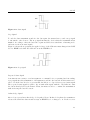
2.2.3 Data Transfer
After the master configured the clock and selected a slave, the data transmission begins. As
described above, the data transfer operates in full duplex mode with the aid of shift registers.
Therefore, any devices connected to the SPI bus must have a internal shift register (see Figure
??).
With every clock pulse the master shifts a data bit over the MOSI line into the shift register
of the slave. The slave shifts at the same time a data bit over the MISO line into the shift
register of the master. The transmission ends after the master free the SS line again.
2.2.4 Communication Modes
SPI has no official specification, therefore it has no specified communication protocol. For
this reason SPI provides the possibility to switch between four communication modes. These
17
2 Background
Figure 2.10: Data transfer among two shift registers
modes are defined by two parameters: The clock polarity (CPOL) and clock phase (CPHA).
The CPOL determines the clock idle state and the CPHA determines whether the data will be
sampled at first or second edge.
CPOL = LOW and CPHA = LOW
The idle state of the clock is set to LOW level and the data will be sampled at the first edge.
The first edge is a rising edge, therefore the following data will also be sampled at a rising
edge (see Figure 2.11).
Figure 2.11: SPI mode 0
CPOL = LOW and CPHA = HIGH
The idle state of the clock is set to LOW level and the data will be sampled at the second
edge. The second edge is a falling edge, therefore the following data will also be sampled at a
falling edge (see Figure 2.12).
CPOL = HIGH and CPHA = LOW
The idle state of the clock is set to HIGH level and the data will be sampled at the first edge.
The first edge is a falling edge, therefore the following data will also be sampled at a falling
18
2.2 SPI
Figure 2.12: SPI mode 1
edge (see Figure 2.13).
Figure 2.13: SPI mode 2
CPOL = HIGH and CPHA = HIGH
The idle state of the clock set to HIGH level and the data will be sampled at the second edge.
The second edge is a rising edge, therefore the following data will also be sampled at a rising
edge (see Figure 2.14).
Figure 2.14: SPI mode 3
19
2 Background
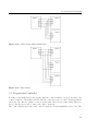
2.2.5 SPI configurations
SPI provides multiple configurations how the slaves can be connected to the master. Mostly
three configurations are used: 3-Wire-Master-Slave, the 4-Wire-Single-Master-Multi-Slave and
the Daisy-Chain.
3-Wire-Master-Slave
In the 3-Wire-Master-Slave configuration, as shown in Figure 2.15, only three wires are required,
because only one slave is connected to the bus. In this case the SS pin can be set fix to HIGH
level and therefore the SS wire is not needed. But some devices requires a falling edge of the
SS line to start interaction and in this cases the SS line is still needed.
Figure 2.15: 3-Wired-Master-Slave
4-Wire-Single-Master-Multi-Slave
The 4-Wire-Single-Master-Multi-Slave configuration is shown in Figure 2.16 and is the mostly
used configuration of a SPI bus. Each slave has an independent SS wire connected to the
master, but shares the MOSI, MISO and SCK wire. As a result the slaves must have tri-state
outputs.
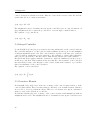
Daisy-Chain
In the daisy-chain configuration (see Figure 2.17) all slaves share the SS and the SCK wire. In
this case all devices connected to the bus are active at the same time, but they do not share
the MOSI and MISO wire.
The structure of the Daisy-Chain configuration is like a chain: the master is connected to the
first slave via the MOSI wire, the first slave is connected to the next slave via the MISO output
to the MOSI input and so on. The last slave in the chain is connected with the master, via
the MOSI output of the slave and the MISO input of the master, again. In this configuration,
all devices act together like a large shift register, that means the data bytes received during a
cycle will be send to the next device during the next cycle.
20
2.3 Proportional Controller
Figure 2.16: 4-Wire-Single-Master-Multi-Slave
Figure 2.17: Daisy-Chain
2.3 Proportional Controller
For all p-controller[Rob13][con12] applies that the control variable y is proportional to the
control deviation e. From this it follows, that the controller reacts on control deviation without
any delay, but only if a variance between actual value and reference value exists. Therefore
the p-controller is not able to remove the offset completely.
The control variable depends on the control deviation e and an amplification factor Kp . The
21
2 Background
control deviation is calculated from the difference between the reference value RV and the
actual value AV at a certain point in time.
(2.1) e(t) = AV · RV
The amplification factor determines how strong the controller reacts on control deviations. A
large amplification factor causes the p-controller to react strongly to small deviation.
The equation of a p-controller is:
(2.2) y(t) = Kp · e(t)
2.4 Integral Controller
I-controllers[Rob13][con12] are proportional to the temporal integral over the control deviations.
The controllers integrates over the control deviation within a specified period t and multiplies
it with an amplification factor Ki . The control variable depends on the time period and the
control deviation. Small time periods causes the control variable to change faster than large
time periods, but then the controller tends to hunt and the system can became unstable.
Integral Controllers regulates until the deviation is completely eliminated, but they are not
as fast as p-controllers. This results from the fact that the control variable of an i-controller
increases slowly because of the integral over the control deviations in contrast to a p-controller
that reacts instantly on the control deviation.
The equation of an i-controller is:
(2.3) y(t) = Ki ·
Zt
e(t)dt
0
2.5 Derivative Element
D-elements[Rob13][con12] reacts on the rate of change of the control deviation and not on the
control deviation itself. They react faster than p-controllers, even on small deviation. But they
are not able to detected permanent offsets. Therefore, a d-element acts only in combination
with a p- and/or an i-element as a controller.
D-elements calculates the rate of change of the control deviation and multiplies it with an
amplification factor Kd . The amplification factor determines how strong the controller reacts
22
2.6 PID-Controller
to the rate of change.
The equation of a d-element is:
(2.4) y(t) = Kd ·
de(t)
dt
2.6 PID-Controller
The PID-controller[Rob13][con12] is a combination of a p-, i- and d-element. Correctly applied,
the controller unifies the advantages and compensates the disadvantages of the three control
elements.
The controller reacts fast on control deviation, because of the p- and d-element. The i-element
of the PID-controller ensures that the offset disappears. The controller reaches fast the set
point, has a small overswing and only for a short period. Therefore, the PID controller is fast,
stable and has no permanent offset.
The equation of the PID-controller is the addition of the equations of the p-, i- and d-elements:
(2.5) y(t) = Kp · e(t) + Ki ·
Zt
e(t)dt + Kd ·
de(t)
dt
0
2.7 Complementary Filter
The complementary filter is used, to combine multiple data. In this project the filter is used
to combine the inclination angles calculated by the accelerometer signal and gyroscope signal
as based on work of [Col07][JR.75][ECM+ 08][SAS12].
The filter acts as low-pass filter and high-pass filter simultaneously. The filter reduces the
disadvantages of the accelerometer and the gyroscope. The gyroscope provides exact results
over short periods but drifts away over a long period. However the accelerometer provides
imprecise results over a short period but good results over a long period. The complementary
filter acts on the one hand as a low-pass filter to reduce the noise of the accelerometer signal
in case of vibration and on the other hand as a high-pass filter to reduce the drift of the angle
calculated by the gyroscope signals.
The complementary filter is a simple alternative to the complex Kalman filter, because it is
easier to understand, implement, and in some cases generates results almost as good as those
created by the Kalman filter[SAS12].
The formula of the complementary filter for two data sets is:
(2.6) y(t) = j · u(t) + i · v(t)
where j · i = 1 and u(t), v(t) represents arbitrary input data at certain time t
23
2 Background
2.8 termios
The termios.h is a C/C++ library for Linux operation systems that provides the possibility to
configure the input, output and transmission of data via a serial port with another terminal or
device. The termios library contains the termios struct:
struct termios {
tcflag_t c_iflag; // input flag
tcflag_t c_oflag; // output flag
tcflag_t c_cflag; // control flag
tcflag_t c_lflag; // local flag
cc_t c_cc[NCCS]; // special characters
}
The termios struct consists of four 32bit masks for the different flags and an array for the
special character sequences which are used as control characters.
Every struct variable configures another area. The c_iflag variable configures how to process
the input before the transmission, for example convert Carriage Return (CR) to Newline(NL).
The c_oflag configures how to process data before output, such as expand tabs to spaces.
The c_cflag configures the general control, for instance enable the parity check, and finally
the c_lflag which configures the terminal properties, for example enable the line-by-line
transmission.
The termios library also provides methods to configure the termios struct or to control the
transmission. It supports two different modes: the canonical mode or cooked mode and the
non-canonical mode or raw mode.
The canonical mode provides the line-by-line transmission which means that complete lines
are processed. A line ends with a control character such as EOL(end of line). However in
the non-canonical mode characters are processed one-by-one and control characters are not
processed, because they often consists of more than one character.
The termios library provide many more possibilities to configure the input, output, the
transmission and the terminal itself, but here only a rough overview should be given.
2.9 Singleton Pattern
The Singleton Pattern[Kau07] is a design pattern which ensures that a class can be only
initialized once. It is possible to set a global access to this instance. This pattern is used
whenever it is important to have only one object of a class, for example to mange the access
to an interface.
A singleton class is initialized by itself and do not provide the possibility to initialize more
instances.
24
3 Components
3.1 USB-ISS
3.1.1 Overview
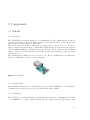
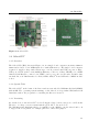
The USB-ISS[Devb], shown in Figure 3.1, is a multifunction USB communications module. It
provides an interface between an USB port and several different kinds of bus systems: I2 C,
SPI, Serial port, Analog Input or Digital I/O.
The module offers the ability to switch the operating voltage between 3,3V or to 5V and to
supply external circuitry with up to 80mA. The USB-ISS supports various fixed frequencies
between 20khz-1000khz to transmit data via the I2 C bus. In the I2 C mode the USB-ISS
always operates as an I2 C bus master and handle the I2 C start/restart/stop sequencing and
acknowledge cycle.
The USB-ISS has two LED: A green one and a red one. The green LED is the power indication
and the red LED the reception of valid commands.
Figure 3.1: USB-ISS
3.1.2 Specific Task
The USB-ISS is the interface to the I2 C bus and is used in the 100kHz mode. It handles the
communication among the Odroid-X2+ , the MPU-9150 and the MD25.
3.1.3 Presetting
The USB-ISS provides different I2 C modes with different frequencies of transmission. To switch
to the 100kHz mode, a write command with the specific register index and value must be send
25
3 Components
to the USB-ISS after the connection is established. This configuration had only to be done
once.
3.1.4 Procedure
Each interaction among the Odroid and an external device goes via the USB-ISS. The USB-ISS
converts the received data, from byte arrays into I2 C bit sequences and transfers it via the bus
to the specific device. It also converts the received I2 C bit sequences from the external devices
back to byte arrays so that the program can process them.
3.2 MD25 - Dual Motor Drive
3.2.1 Overview
The MD25[Deva], shown in Figure 3.2, is a H-bridge dual motor driver and can be used in I2 Cor Serial mode. It requires 12V supply voltage to operate and has a integrated 5V regulator to
supply external circuitry up to 1A peak or 300mA continuously. The module is able to read
motor encoders to determine the distance traveled and offers the ability to control the motors
independently. It has a feature to facilitate the steering and offers the ability to configure the
acceleration of the motors. The MD25 also provides the ability to read out the voltage of the
connected battery and the used power consumption of the motors. Similar to the USB-ISS
it has two LEDs: a red LED and a green LED. But in this case the red one is the power
indication and the green one flashes whenever a valid command was received.
Figure 3.2: MD25
26
3.3 MPU-9150
3.2.2 Specific Task
The MD25 is connected to the Odroid-X2+ via the I2 C bus and supplies the bus with 5V
supply voltage. The module acts as a slave device and controls the two connected EMG30
motors.
3.2.3 Presetting
Two configurations need to be done before the MD25 is used. The first is a hardware
configuration and must only to be set once. It is needed to switch the MD25 to the I2 C mode.
This is achieved by removing the jumper of the configuration pins.
The second configuration is a software configuration that sets the acceleration of the motors
and must be done each time the robot starts. In order to set the acceleration the Odroid
sends a write command via the USB-ISS and the I2 C bus to the MD25 after the program was
started and a connection was established. This command contains the index of the acceleration
register and the value that should be written into this register. After the acceleration is set
the MD25 is ready to work.
3.2.4 Procedure
In each cycle the Odroid sends a write command via the USB-ISS and the I2 C bus to the
MD25. This command contains the register index of the motor and the speed value. After the
speed value is written into the register, the MD25 increases or decreases the speed every 25ms,
based on the acceleration rate.
3.3 MPU-9150
3.3.1 Overview
The MPU-9150[Spa][Inv12][Inv], shown in Figure 3.3, is an inertial measurement unit. It
contains a triple-axis accelerometer, a triple-axis gyroscope, a triple-axis magnetometer and
a temperature sensor. The module requires a supply voltage between 2.4V and 3.46V and
an operational current up to 4.35mA. The integrated gyroscope and accelerometer have
programmable full-scale ranges. The full-scale range of the gyroscope can be set to ± 250, ±
500, ± 1000 or ± 2000 degrees per second(dps) and the accelerometer to ± 2g, ± 4g, ± 8g and
± 16g. The magnetometer has a full-scale range of ± 1200µT. The MPU-9150 is extremely
shock tolerant in fact up to 10,000g.
27
3 Components
Figure 3.3: MPU-9150
3.3.2 Specific Task
The MPU-9150 is connected to the Odroid using the I2 C bus and the USB-ISS, and acts as a
slave device. It provides the gyroscope and accelerometer data to determine the inclination
angle.
3.3.3 Presetting
As described above the MPU-9150 needs supply voltage between 2.4V and 3.46V, but is
connected to a 5V circuit supplied by the MD25. Therefore, a voltage converter is used to
transform the supply voltage from 5V to the required 3.3V
After each start up of the robot the MPU-9150 is in a sleep state. To wake up the MPU-9150,
a write command is transferred to the MPU-9150 via the USB-ISS and the I2 C bus. This
command contains the register index of the power management of the MPU-9150 and the
specific value to configure the power management. After the MPU-9150 receives this command
and wrote the received value into the specific register, the internal clock starts and the full-scale
rages of the gyroscope and accelerometer are set to default. The default full-scale rages of the
accelerometer is ± 2g and of the gyroscope ± 250dps.
3.3.4 Procedure
In each cycle the gyroscope and accelerometer data are needed to calculate the current
inclination angle. Therefore, during a cycle the Odroid requests for the gyroscope and
accelerometer data by sending two read command. The first command reads the data from
the accelerometer and the second from the accelerometer.
28
3.4 Odroid-X2+
Figure 3.4: Odroid-X2
3.4 Odroid-X2+
3.4.1 Overview
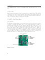
The Odroid-X2+ [Har], shown in Figure 3.4, is a single-board computer, measures 90mm x
94mm and is based on a 1.7GHz Quad Core with 2GB memory. The single board-computer
requires 5v supply voltage with current up to 2A. It possesses six USB 2.0 ports, a Micro
USB port, a RJ45 jack for a 10/100Mbps Ethernet connector, a Micro HDMI port, a MIPI
Camera Serial Interface connector, an UART console port, a slot for SD cards, an Audio-Out,
an Audio-In, a 50 Pins Interface for LCS, GPIO, ADC, I2 C and SPI and a eMMC module
socket.
3.4.2 Specific Task
The Odroid-X2+ is the brain of the Racer and uses an embedded Multimedia Card(eMMC)
with 16GB. The operating system running on the Odroid, is a specialized Xubuntu 13.04
distribution where the program for controlling the Racer is executed.
3.4.3 Presetting
As described above the Odroid-X2+ needs 5V supply voltage, but is connected to a 12V circuit.
Therefore, a voltage converter transforms the given 12V to the needed 5V.
The Xubuntu 13.04 distribution had to be installed on the eMMC to use the Odroid and tools
to support the development, for example qtCreator, emacs and gnuplot.
29
3 Components
To accomplish that the program was able to communicate via the USB port with the external
devices, the access permission must be set.
3.5 TopFuel LiPo ECO-X 5000 3S
3.5.1 Overview
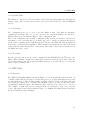
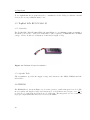
The TopFuel LiPo ECO-X 5000 3S[Hac], shown in Figure 3.5, is a lithium-polymer-accumulator
and is the power source of the racer. It has three cells, a capacity of 5000mAh and a nominal
voltage of 11.1v. It has a load duration of 20C and a weight of 377g.
Figure 3.5: Lithium-Polymer-Accumulator
3.5.2 Specific Task
The accumulator provides the supply voltage and current for the MD25, EMG30 and the
Odroid-X2+ .
3.6 EMG30
The EMG30[Devc], shown in Figure 3.6, is a 30:1 gear motor with a integrated encoder. The
kg
motor requires 12v supply voltage and current up to 2.5A. It has a rated torque of 1.5 cm
,a
no-load speed of 216 rpm and a rated speed of 170 rpm. The integrated encoder counts 360
steps per output shaft turn and can be read by the MD25.
30
3.7 Assembly
Figure 3.6: EMG30
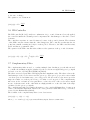
3.7 Assembly
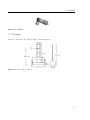
Figure 3.7 shows the Two-Wheeled-Racer with dimensions.
Figure 3.7: Two-Wheeled-Racer
31
4 Software
4.1 Overview
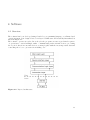
The software has been developed using C and C++ programming language on a Linux based
operation system. It is designed based on a layered architecture and is strictly hierarchical, as
shown in Figure 4.1.
The software operates in cycles. In each cycle the program executes a predefined sequence
of operations to attend multiple tasks: communicating with external devices, processing
the received data from external devices, creating logfiles with the most important data and
controlling the robot to prevent it from falling over.
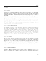
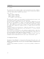
Figure 4.1: Layered architecture
33
4 Software
4.2 Software Architecture
The software is constructed based on a layered architecture. It consists of four layers: the
main logic layer, the device interface layer, the communication logic layer and the connection
layer. Each of these layers has a specific task. The communication among the layers is strict
hierarchical, that means that a layer is only able to communicate with a layer that is directly
above or beneath.
4.2.1 Main Logic Layer
The main logic layer provides the entry point and contains the main cycle of the program. The
main logic layer has access to the device interface layer and therefore access to the external
devices. It provides a platform where the data from the external devices can be accessed and
contains the controller that processes received data and determines the speed value for the
motors.
4.2.2 Device Interface Layer
The device interface layer is a kind of interface to the external devices. It provides methods to
interact and configure the external devices. It also contains data from the external devices
which are accessible by the main logic layer. The device interface layer contains no logic.
4.2.3 Communication Logic Layer
The communication logic layer provides the logic behind the methods of the device interface
layer. The layer is responsible to create byte array in a way that the I2 C interface, the USB-ISS,
can handle them and pass them to the connection layer. It also converts the byte arrays
received from the connection layer into the required data type and pass it to the interface
layer.
4.2.4 Connection Layer
The connection layer is written in C and has two main tasks.
The first task is to establish or to close the connection to the I2 C interface and to guarantee
that only one connection to the I2 C interface exists. To accomplish this the singleton pattern
is used.
The second task is to handle the communication to I2 C interface, that means to transfer
the received byte arrays from the communication logic layer to the USB-ISS and to pass the
received byte arrays from the interface back to the communication logic layer.
34
4.3 Procedure
4.3 Procedure
After the program has started, the initialisation phase begins. In this phase the required
objects are initialised. The three main task of this phase are to establish the connection to the
USB-ISS, start the internal clock of the IMU and set the configurations of the MD25 and the
IMU. Afterwards the IMU data is read once to calculate the inclination angle at start time.
After the initialisation phase has completed successfully, the main cycle begins: the control
cycle. The control cycle proceeds as follows: the first step of the cycle is to set the speed of
the motors depending on the calculated inclination angle. The next step is to read the current
accelerometer and gyroscope data from the IMU and calculate the current inclination angle
with the help of the complementary filter. Finally the most important information is printed
on the console and afterwards written into the logfiles. Now the cycle starts again with setting
the motor speed.
At the end of the program the logfiles will be closed and the speed of the motors set to null.
35
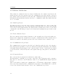
5 Project
5.1 Initial Situation
At the beginning of the project only the hardware components were available: the MD25 with
motors and wheels, the MPU-9150, the USB-ISS and the Odroid. Based on these components
the planing phase began.
5.2 Planing Phase
In the beginning phase of the project, the first task was to specify the general conditions for
the construction: what kind of material should be used to construct the Racer, how should
the racer be designed and where should the components be mounted to reach a compromise
between stability and high dynamics.
The choice of the construction material fell on wood, because wood is a cheap raw material
and it is easy to work with.
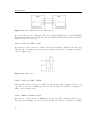
The look of the Racer is a bit like a ladder on two wheels. This design provides two advantages:
on the one hand there is enough space at the bottom of the Racer to mount most of the
components. On the other hand a weight can be attached at an arbitrary point of the "ladder".
This makes it possible to change the centre of gravity and therefore alter inertia and dynamics
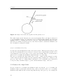
of the robot. Figure 5.1 shows a sketch of the Racer.
Figure 5.1: Sketch of the Racer
37
5 Project
After the general conditions of the construction are clarified, the technical details of the Racer
had to be defined: what kind of operating system, programming language and communication
system or protocol should be used.
As operating system a Linux based distribution was chosen and C/C++ as programming
language. The choice of the programming language fell on C/C++ because it is a hardwarerelated programming language.
For the communication among the Odroid and the external devices an I2 C bus was chosen.
This has two advantages: the first is that all devices are able to use the I2 C protocol and
therefore able to transmit data via the I2 C bus. The seconds is that the USB-ISS is able to
handle the I2 C start/restart/stop sequencing and acknowledge cycle.
5.3 Interaction with the MD25 via the USB-ISS
After the general conditions were specified the prototyping phase started. The first milestone
was to drive the motors and read the voltage of the power source via the MD25.
The USB-ISS was the first component to handle with, because the USB-ISS provides the
interface between the Odroid and the I2 C bus.
The documentation leaded to the incorrect conclusion that an additional driver for Linux
operating systems was needed to use the USB-ISS. This resulted from the fact, that the
documentation where only available for Windows operating systems. After a while of trying
to run the USB-ISS with the additional driver, it finally turned out that the standard Linux
USB driver was sufficient.
The next step was to establish a connection to the USB-ISS and to communicate with it.
An application with the associated source code[Har] was found which was able to establish a
connection to the USB-ISS on Linux operating systems.
Based on the source code of the application, a short test program was written. This program
was able to set the operation mode of USB-ISS, was able to read the serial number, the module
ID and the firmware version of the device.
Once the program worked properly, the next task was to figure out how to transfer data to an
external device connected to the I2 C bus via the USB-ISS. In preparation of this the decision
was made to upgrade the firmware of the USB-ISS from version 4 to version 5, because it
provides an additional very useful function. It allows to check the bus whether a device with
a specific address is connected. This upgrade however was required to be performed on a
windows machine, since the official documentation does not provide a solution to upgrade from
a Linux system.
After the update was done, a device was required that could be connected the I2 C bus to test
the new function. Thus, the MD25 was attached to the bus. To test the new function it was
sufficient to supply only the microcontroller on the MD25 by the 5V supply voltage provided
by the USB-ISS.
After the function was tested and the MD25 was detected by the USB-ISS, the next step was
to interact with the register of a connected device. Due to the fact that the USB-ISS is able
to mange the start/restart, stop, and ACK cycles automatically, the data and commands must
be stored in a byte array and transferred to the USB-ISS. The USB-ISS converts the received
38
5.4 Construction of the Racer and installing Ubuntu on the Odroid
data into a I2 C bit sequence and transfers it via the bus to the specific device. USB-ISS
specification[Devb] has instructions how commands and data must be stored in a byte array
to execute a specific task.
The LEDs of the MD25 and USB-ISS flashed, consequently both devices received valid
commands but sometimes the received data was not correct or did not make sense at all.
Therefore, the motors were connected and the MD25 was supplied by the 12V supply voltage,
because the missing of these parts could cause the problem. As a result of that, it turned out
that the writing worked properly. This follows from the fact that the the application was able
to change the speed of the motors, but the request of data from the external device caused
problems. It seemed that the test application, which has in the meantime grown large and
unstructured, caused the problem. The problem should be solved when a new application was
build.
However, despite all these difficulties the first milestone was reached.
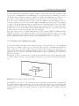
5.4 Construction of the Racer and installing Ubuntu on the Odroid
The next goal was to build the skeleton of the Racer and to install Ubuntu on the Odroid.
Therefore, the first task was to buy the material and assemble the skeleton of the racer. The
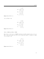
robot was build as shown in the Figure 5.2. This structure features a simple design while still
Figure 5.2: Sketch of the Racer with components
offering sufficient space for the components and the possibility to change the centre of gravity
of the racer.
The Odroid, the MD25 and the two motors with the corresponding wheels are mounted on the
board at the bottom of the robot. The MPU-9150 is attached at the upper half of the racer,
the part that is designed like a "ladder". At this position the IMU detects early and small
changes of the inclination angle of the Racer. The "ladder" provides the ability to change the
centre of gravity depending on the position of the weight. As a weight, the battery was used
later in the project.
39
5 Project
After the skeleton of the robot was build, the next task began. The next task was to install
and run Ubuntu on the Odroid.
Installing a new operating system on the Odroid turned out to be more difficult than expected.
Firstly the officially supported operating systems are Android versions. Instructions to install
one of the many Linux distribution are spread over several community portals but most of
them turned out to be not working.
Eventually after trying to install multiple versions of Ubuntu and its variants on the SD card,
the only working combination was Xubuntu 13.04 for Odroids on the eMMC.
Finally the Racer was ready to get its components mounted and afterwards the second milestone
was reached.
5.5 Request Data from the IMU
Xubuntu runs on the Odroid, the transmission of bytes to the USB-ISS, the communication
between the USB-ISS and the MD25 via the I2 C bus and the control of the motors worked.
Hence, the next goal was to read data of the accelerometer and the gyroscope.
The first step to reach the next milestone was to attach the MPU-9150 to the I2 C bus. To
achieve this, the wires of the I2 C bus were soldered on to specific pins of the IMU and the
address was used as specified in the product specification[Inv].
Running a first test however revealed another problem: the IMU could not be detected.
Since the IMU has no LED to indicate whether a signal has been received correctly or not the
wires were checked with a multimeter to confirm they were soldered correctly, which was in
fact the case.
The red LED of the USB-ISS flashed whenever the application has send a command, thus the
interface must have received valid commands and the problem must be either occurred during
the transmission via the I2 C bus or on the IMU itself.
To exclude an error during the transmission, the signal transmission was monitored with an
oscilloscope. It showed that the USB-ISS transmitted the correct address but the IMU did
not recognize it as its own and therefore it did not return an acknowledge signal. This fact
implies that the problem was either that the IMU was damaged or that the address was not
the address the IMU expected.
Eventually the problem was that the specified address in the product specification disregarded
the read/write bit at the LSB position. Therefore, the given 7 bit binary number had to be
shifted one bit left to get the correct address. Afterwards, the address of the IMU was changed
in the application and therefore the MPU-9150 could be found. As a result of that, the next
task was to read out the data of the accelerometer and gyroscope.
The data of the accelerometer and gyroscope are stored in internal registers of the IMU. Each
value of the X-, Y- and Z-coordinates consist of two 8 bit numbers and form a 16 bit two’s
complement number, therefore two registers must be read and added up afterwards. To sum
up the bytes, the high byte must be shifted eight digits left and added to the low byte.
To read out the data, the test program had to be extended by a method that reads out the high
byte and the low byte of the value of a coordinate. These bytes then needed to be processed
as described above, but the return value of the application was always zero.
40
5.5 Request Data from the IMU
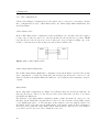
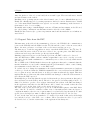
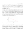
Figure 5.3: Raw data of the accelerometer and the gyroscope
To understand this behaviour more information was needed. After start up the IMU is in a
kind of sleep mode[Inv12]. In this state the internal clock of the IMU did not work and thus
the IMU did not provide any data. To wake up the IMU and start the internal clock, a specific
value must be written to the specific power management register.
After the program was updated and the internal clock of the IMU was started, the application
returned values that changed. As a result of that, the program was extended so that the values
of all coordinates were read and monitored. The values varied heavily although the IMU did
not move, therefore it could not be normal measurement noise.
For this reason, the code of the test application was inspected and afterwards decided that
the time had come to write a complete new application. The reason for that was on the one
hand that the source code had grown large and became rather unstructured and on the other
hand contained constructions that could cause errors. For example the test application did
not consider whether a read command failed. Therefore, it could happen that two values are
added even so they are not supposed to be added or variables get assigned wrong values.
Another problem of the test application was that the test application read the register one by
one instead of using a burst-read. A burst-read is a request command that starts reading at
a selected register and reads the following registers afterwards. A burst-read reads as many
registers as specified and is supported by the IMU and the MD25. The IMU ensures that
during the burst-read the values stored in the registers do not change, therefore sampled values
of the current cycle could not be mixed up with values sampled from the previous cycle.
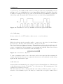
After a period of coding the new software was at the same level as the test application, but the
new application ran much more stable and provided new functions, for example the application
was now able to store the data in a logfile for better monitoring and the ability to plot the
results. After some tests the results were plotted and it could be verified that the values of the
accelerometer and the gyroscope were correct except for some small measurement noise. The
Figure 5.3 shows the raw data obtained from the IMU. Now the application was able to read
out the data of the IMU correctly and thus the third milestone was reached.
41
5 Project
5.6 Connected all Devices to the same I2 C Bus
The next step was to attach the MD25, IMU and USB-ISS to the same bus, but every time
the application tried to request data from the MD25 or the IMU an error occurred. The
devices repeatedly were shown as temporally not available. The issue was that the same
serial port in one application was opened several times and the alternating transmission via
different connections caused some trouble. Therefore, the program code was changed to allow
at most one connection to the serial port instead of one for the MD25 and one for the IMU.
To accomplished this the singleton pattern was used. That means whenever a connection to
the USB-ISS is needed, the program checks whether a connection is already established. If so
the program will not open a new connection but returns a reference to the existing connection
object. This ensures that all objects use the same connection to the USB-ISS and do not
impede each other.
Although this reduced the occurrence of the error, but it did not solve it entirely. This is
where the termios library came in. It provides the ability to configure how to transmit data
between devices and offers methods to manipulate the transmission. For example, it allows
to change the transmission mode to a raw mode. In this raw mode characters are processed
one-by-one and special characters are not interpreted. As a result of that, the error, that the
device is temporary not available, was eliminated, but at this point a new error occurred. The
received data was not correct whenever the devices were read alternately. After some further
observations it became clear that the received values where in fact delayed. The application
received data that was expecting earlier and therefore the received data was assigned to wrong
variables.
To fix this problem, sleep functions were implemented because the process time of the external
devices was disregarded, but this did not solve the problem. Tests showed that this problem
occurred whenever the application requests data from the one device in one step and in the
next step from the other device. In this case the next few requests return wrong values because
the stream still contained old bytes. A method that clear the input stream before the next
request was needed.
The method tcflush from the termois library provided this capability and solve the problem.
Now the application was able to read out the data of the motors and IMU alternately and
returned correct values.
The fourth milestone was reached.
5.7 Put together the Two-Wheeled-Racer
After the data transmission worked correctly, the next task was to complete the assembly of
the Racer. Thais means to attach all components on the racer, to connect the MD25, IMU
and the USB-ISS to the I2 C bus, supply all components with the supply power and run the
application to control the racer and devices on the Odroid.
Once all components were attached to the racer and connected to the bus, the components
needed to be powered by the supply power. As supply power a lithium-polymer-accumulator
that provides 12V supply voltage was used, but the Odroid requires 5V supply voltage. Thus,
42
5.8 Calculate the Inclination Angle
a voltage transformer was required. At first, a linear converter was used but it quickly became
very hot and eventually shut down. This happened because the Odroid requires up to 2A and
the linear voltage transformer was not designed to handle such high amperage. Therefore, a
step-down converter was used and integrated between the power source and the Odroid.
A second voltage transformer was needed, because the IMU receives the supply power not
directly from the power source but from the MD25. The MD25 has an integrated 5V regulator
to supply external circuitry and therefore supplies the I2 C bus with supply voltage. The IMU
is supplied via the I2 C bus but requires only 3.3V. As a result of that, a voltage transformer
was integrated between the MD25 and the IMU. This time a linear converter was used and
worked properly because the amperage was not that high.
After all components were supplied with supply voltage and the IMU, the MD25 and the
USB-ISS connected to the bus and mounted on the racer, the application was copied on the
Odroid. Afterwards a test phase followed to check whether all wires are connected correctly
and the application runs correctly on the Odroid, which turned out to be the case.
5.8 Calculate the Inclination Angle
Now the assembly of the Racer was complete and the controller ready to be programmed,
hence the second phase of the project began. The first goal was to determine the inclination
angle of the racer. To achieve this, the accelerometer data and gyroscope data had to be
processed in a way that the current inclination angle could be calculated. The inclination
angle was needed, because depending on this angle the speed and direction of the motors
should be regulated.
The first step was to consider how to determine the inclination angle at the start time. The
coordinate system depends on how the IMU was mounted to the racer and is shown in Figure
5.4.
Figure 5.4: Coordinate system of the IMU
If the IMU does not move, the data from the accelerometer represents the gravitational
acceleration and points towards the center of the earth. It represents a vector that points
vertical down. To evaluate the inclination angle, the normal of the xy-plane was calculated
and afterwards the angle between the gravity vector and the normal was determined as shown
in Figure 5.5.
43
5 Project
Figure 5.5: Angle between the the xy-plane and the gravity vector
The resulted angle was 90◦ when the racer was vertical upright. Hence, 90◦ must be subtracted
to get an inclination angle of 0◦ when the racer is vertical upright. Finally, the result was
multiplied with -1 to determine the front side of the racer. Thus, the inclination angle is positive
when the racer inclined forwards and vice versa. Later it turned out that the inclination can
also determined by using the formula:
(5.1) θ = arctan2 (accelz , accelx )
Now the approach was implemented and some tests were made. This approach worked properly,
but did not work when the racer accelerated or slowed down, because in this cases the vector,
representing the accelerometer data, does not point down vertically. Therefore, another method
was needed to determine the inclination angle when the robot is moving.
The gyroscope measures the angle change rate for each coordinate and the integral over time
of these data represents how much degree the angle had changed in this period. Therefore, the
gyroscope data of the y-coordinate must be integrated over a certain time period and add it
to the previously determined angle to get the current inclination angle of the racer.
5.9 Remove the Angle Drift
Now two methods to determine the inclination angle were known: one to determine the
inclination angle at start time with the help of the accelerometer and one to determine
inclination angle while the Racer was moving with the help of the gyroscope. Accordingly, the
44
5.9 Remove the Angle Drift
next task was to find a controller that regulates the motors based on the current inclination
angle of the robot to prevent the robot from falling over. To gather information about
controllers and how other solutions solved this problem, several different papers and other
solutions have been studied. A controller that was easy to understand and often used in
different projects was the PID controller. The PID controller is easy to implement and provides
good results, if the controller is applied correctly. Consequently the PID controller was the
right controller for this project.
After the PID-controller was implemented the configuration of the parameters began. But
after a while of trying to set the parameters correctly, the Racer was not able to balance
longer than a few seconds. The first thought was that the motors were not strong enough
and reacted too slowly. The MD25 provides the ability to configure the acceleration of the
motors. Therefore, the acceleration level was set to maximum. However, this did not show
any improvements.
To figure out what exactly causes the problem, the program code was extended so that more
logfiles were created. The new logfiles contained the angle, the values of the PID controller
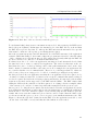
elements, the motor speed, the accelerometer data and gyroscope data. This data revealed that
the calculated angle drifts which means the angle changes even the IMU did not move the IMU.
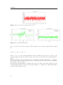
This came from the fact that the gyroscope provides exact results over short periods[SAS12],
but drifts away over a long period as shown in Figure 5.6.
Figure 5.6: Angle calculated by the gyroscope data
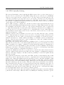
The accelerometer on the other side provides imprecise results over a short period but good
results over a long period[SAS12] (see Figure 5.7):
For this reason, a solution must be found to fuse the data. This solution should combine the
strengths and cancel out the weaknesses of the both sensors to determine the current inclination
angle without drift. One possibility was the complementary filter: the complementary filter
uses the advantages of the gyroscope and the accelerometer and tries to remove the drift of
the gyroscope by the help of the accelerometer.
To use the complementary filter one needs to determine the current inclination angle from
45
5 Project
Figure 5.7: Accelerometer data in x-direction
Figure 5.8: Complementary filter
gyroscope and accelerometer separately. These angles are the averaged using different weights
as:
(5.2) θi = j · (θi−1 + α) + k · β
where j + k = 1, α the current inclination angle determined by the gyroscope data, β the
current inclination angle determined by the accelerometer data and θ the actual inclination
angle.
The filter is simple to understand and easy to implement only the weights had to be adjusted,
therefore the next task was to implement the complementary filter and afterwards adjusting
the weights of the two angles.
After the filter was implemented, adjusted and tested, the drift of the angle calculated by the
complementary filter was removed as shown in Figure 5.8. Thus, the complementary filter
solved the angle drift problem.
46
5.10 PID Controller Setting
5.10 PID Controller Setting
The next problem which occurred was that the MD25 was not able to set the desired speed of
the motor in one controller cycle. The MD25 changes the speed of the motors of maximum
value 10 every 25ms, but the controller cycle took only round about 15ms, therefore the
controller cycle must be prolonged. In order to prolong the controller cycle, sleep functions
were implemented and afterwards the parameters of the PID controller had to be adjusted.
Another issue of adjusting the parameters was the fact, that the reaction of the motors depend
on the charge level of the accumulator.
After a while of trying to configure the controller, it slowly became apparent that the motors
have reached their limits with weight and inertia of the racer. This results from the fact, that
the accumulator was attached on the top of the "ladder" and thus the centre of gravity was
too high. That means minor deviations from the balancing point made the racer falling over,
because the motors do not have enough power to compensated the velocity of fall. Therefore,
the accumulator was mounted at the bottom of the ladder, but now the racer became very
unstable and started to oscillate.
Multiple positions for the accumulator were tried, but every time either the centre of gravity
was too high and therefore the motors were not able to react fast enough or had the power
to compensate the velocity of fall to prevent the racer from falling over. Or the racer was to
unstable and started to oscillate until it was falling over. Finally, round about 20cm from
the top of the racer were removed to reduce weight and to reduce the oscillation when the
accumulator was mounted at the bottom.
This changed the system behaviour and the accumulator had to be placed at a new position
where the motors were able to react fast enough and have the power to prevent the robot from
falling over while not becoming too unstable. Several positions and parameter configurations of
the controller were tested and finally a position was found. Now the accumulator was attached
halfway up of the Racer. Tests showed that the robot was able to hold itself up longer than
before, but the parameter configuration was still not correct.
To make the adjustment easier the robot was remote controlled via a ssh connection from a
different computer in the same network. This offered the advantage of adjusting the parameter
without connecting a display to the Racer and the possibility to review the logfiles directly
after the test runs.
The logfiles showed that the i-component of the PID controller became immense and for this
reason the p- and d-component were not able to compensated the i-component when the robot
managed it to change the inclination direction and therefore the i-component was limited. This
limitation did not change much at all, but shows a further problem. The controller regulates
the motors based only on the inclination angle. This leads to the fact that the motors stopped
when the balancing point was reached. This fact caused the problem that every time the
Racer was driven in a direction to hold up itself and reached the balancing point only for a
control cycle, but did not change the inclination direction, the motors stopped and the robot
was falling in the same direction again. Thus, the controller tried to compensated the falling
velocity again which caused a more and more unstable system.
To reduce this behaviour the offset was weighted depending on the angle between the balancing
point and the current angle. This was achieved by shifting the balancing point in the opposite
47
5 Project
direction of the inclination direction, the further the larger the inclination angle was. The
result was that the Racer now was able to hold up itself longer then before.
5.11 Result
The result of the project was on the one hand the Two-Wheeled-Racer, which was build of
several individual hardware components that communicate via an I2 C bus. On the other hand
software that provide methods for requesting and transmitting data among the components
and processing data. The software also contains a PID controller that prevent the robot from
falling over, even if only for a time.
48
6 Comparison to other solutions
6.1 Self-Balancing Two-Wheeled Robot
This approach was developed by Brian Bonafila, Nicklas Gustasson, Per Nyman and Sebastian
Nilson[SAS12].
6.1.1 Overview
The self-balancing two-wheeled robot is based on a inverted pendulum balancing on two
wheels and was build with LEGO Mindstorms. The core piece of the robot is the NXT, a
programmable robotics kit with a 32-bit ARM7 microprocessor. To run the real-time operation
systems nxtOSEK on the ARM7 the bootloader was modified.
To prevent the robot from falling over a Linear Quadratic Regulator(LQR) is used and is a
state-based controller. Three sensors are used to determine the system’s state of the robot: an
accelerometer and a gyroscope to calculate the inclination angle and an encoder to determine
the position and speed.
The main focus of the project was to stabilize an unstable system and rejecting disturbance.
6.1.2 Hardware
The structure of the robot was kept simple. The centre of the robot is formed by the NXT
unit. On both sides of the NXT the two motors with the corresponding wheels are attached.
The gyroscope and accelerometer are mounted on the NXT.
6.1.3 Software
The software can be separated in three parts: the initialization module, the digital control
system and the human machine interface.
The initialization Module has two task: the first is to calibrate the gyroscope, that means to
determine the gyroscope offset. The second is to initialize the required variables.
The digital control system consists of three modules: the sampling module, the estimation
module and the LQR controller module. The sampling module reads out the sensor data of
the gyroscope accelerometer and encoder with a sample rate of 250Hz. The estimation module
estimates next system’s state and the LQR controller module generates the signals to control
the motors.
49
6 Comparison to other solutions
The last part is the human machine interface and contains two modules: the display module
and the button module. The display module displays relevant informations on a display with
a sample rate of 20Hz. The button module is responsible for the user interaction for example
the start of the controller after pushing the button.
Procedure
After the robot starts up and the initialization is done the sampling module began to read
the sensor data. Afterwards the data is handed over to the estimation module where the next
system’s state with the help of a Kalman filter and the sensor data estimated. Based on this
state the LQR controller module generates a signal to control the motors.
6.1.4 Controller
To determine the system’s states the accelerometer, gyroscope and encoder data are needed.
To calculate the inclination angle, the gyroscope signal is integrated and afterwards combined
with the inclination angle calculated by the accelerometer data. To combine the two angles
the complementary filter is used. To calculate the inclination angle with the data of the
accelerometer the following function is used:
(6.1) θ = arctan2 (accelz , accelx )
where accelx and accelz are the accelerometer data along the x- and z-axes.
To determine the position and speed of the wheels the encoder is used.
The robot has two control schemas: the first stabilize the robot at its original position, that
means it tries to hold the position. The second tries to stabilize without trying to hold the
position, that means after pushing, the robot rolls forward to stabilize and remain at the
position where it stops.
To accomplish this the LQR controller regulates the motors to stabilize the system. The
motors are control with the supply voltage, this means the higher the voltage the faster the
motor rotates.
6.1.5 Comparison
This approach needs a well-founded background knowledge on the one hand to describe the
system of the robot mathematically and on the other hand in cybernetics to control the motors
based of the current state of the robot.
The project focused on creating a controller and not on constructing a robot, therefore a
hardware was used that already worked and is compatible to other components that can be
attached to the system. Hence, there was no need to mind how the hardware was working or
how the devices communicating among each other.
Compare to this solution the controller of the Racer is less complex and no well-founded
background knowledge in cybernetics were needed, but using a PID controller without a
50
6.2 Zilog ZNEO based Self-Balancing Robot
mathematical system description that control the robot only based on the inclination angle
quickly reach its limit.
The construction of the Racer is more complex compared to this solution, this results from
the fact that the Racer is build out of several different components that are connected and
communication via an I2 C bus. For this reason the Racer can be a easily and nearly arbitrary
upgraded.
6.2 Zilog ZNEO based Self-Balancing Robot
This approach was developed by Spemcer Bridette[Bur07].
6.2.1 Overview
The Self-Balancing Robot is a two-wheeled robot. It uses two reflective objective sensors to
calculate the inclination angle. The core piece of the robot is the Zilog ZNEO microprocessor.
The microprocessor process the data from the sensors and calculates the inclination angle
which is used by an PID algorithm. To prevent the robot from falling over the microprocessor
generates signal based on the information provided by the PID controller to regulate the two
servo motors. Data is transmitted via the serial I/O pins.
The robot forms an inherently unstable platform that is highly susceptible to tip over.
6.2.2 Hardware
The robot was constructed with the scooterbot kit. The scooterbot kit contains two round
plates with 7" in diameter, two 12 " wheels and two servo motors, and the required screws and
wires.
The two plates are attached with four risers to each other. The bottom plate has cutouts for
the wheels and brackets to mount the two servo motors. The upper plate has a central hole to
pass wires. Additionally the two plates provide the possibility to mount extra devices.
The brackets of the motors were mounted from the bottom side to the bottom plate. This
modification were done because otherwise the robot was not able to tip over because the
distance to the ground was to small. On this brackets the sensors were mounted, too. The
motor controller that regulates the motors is attached on the bottom plate and on the top of
the upper plate the microprocessor is mounted.
The two motors are connected to a motor controller that receives signals from the microprocessor. The motor controller process these signals an regulates the motors based on these
signals. Attached to the motor are the two wheels. The sensors are directly connected to the
microprocessor.
51
6 Comparison to other solutions
6.2.3 Software
The architecture of the software is a layered based structure and consists of four layers: the
hardware abstraction layer, the device interaction layer, the integration layer and the user
interface layer. Each layer has a specific task, but the interaction among the layers is not
strictly hierarchical.
Hardware Abstraction Layer
The hardware abstraction layer forms the interface to the microprocessor ports and registers
and is required to interact with the onboard device peripherals for example to control the
LEDs.
Device Control Layer
The device interaction layer forms the interface to the external devices: the motor controller
and the sensors. It provides on the one hand functions to retrieve data from the devices or
transmit commands to control the devices and on the other hand it provides the possibility to
configure the devices. The layer is also for the calibration of the sensors responsible.
Integration Layer
The integration layer contains the PID controller. In this layer the sensor data are processed
and based on this information signals are transferred to the motor controller to control the
motor and prevent the robot of tipping over.
User Interface Layer
The user interface layer provides the possibility to interact with the robot during the runtime.
The main task of the layer is to test, monitor and exercise the functions provided by the other
layers.
6.2.4 Controller
To control the robot and thus prevent the robot from tipping over a PID controller is used.
The controller regulates the motors depending on the inclination of the robot. To determine
the inclination the two reflective object sensors provides the controller with data.
The sensor consists of an infrared emitting diode and a NPN silicon phototransistor. These
two components are mounted in a protective housing to minimize noises. The phototransistor
measures the reflected light from the LED and varies the voltage based on the measured value.
The voltage is converted into a digital signal to process the data. Based on this data the values
52
6.2 Zilog ZNEO based Self-Balancing Robot
are mapped on a range from -1000 to 1000. The value 0 means the robot is vertical upright, a
negative value means the robot inclining forward and vice versa.
Depending on this values the motor is controlled so that the value is close to 0.
6.2.5 Comparison
This approach is similar to the solution of the Racer-project. Both approaches use a PID
controller that regulates the motors depending on the inclination angle to prevent the racer
from falling over, but based on data from different sensors. The software architecture is in
both solution a layer based structure. The construction is function-oriented and well suited
for balancing because of the wide form of the robot provides a certain level stability.
The two solution are very similar but the construction of the this solution is well suited for
balancing, but the brain of the Racer is a fully-fledged single board computer instead of the
microcontroller and provide therefore more possibilities to use.
53
7 Conclusion
7.1 Summary
The background-knowledge of the used technology were given. An overview of the used
components and the specific task in the Two-Wheeled-Racer were depicted. The architecture
and procedure of the software developed during the project were described. The Procedure
of the project was described with the initial situation and the result. Finally two further
approaches were briefly presented and compared to the Two-Wheeled-Racer solution.
7.2 Future Work
Creating a detailed mathematical model of the Racer to use a more complex controller to
control the robot more accurate. As a result of that the software and controller can be extended
so that the racer does not only try to balance but drive around.
After the Racer is able to drive around it can be used for different tasks, for example a camera
can be mounted on the Racer to sense the surrounding.
55
Bibliography
[Bur07]
S. Burdette. A Zillog ZNEO based Self-Balancing Robot with PID control, 2007.
The George Washington University. (Cited on page 51)
[Col07]
S. Colton. The Balance Filter:A Simple Solution for Integrating Accelerometer
and Gyroscope Measurements for a Balancing Platform, 2007. (Cited on page 23)
[con12]
Regler und Regelstrecken, 2012. (Cited on pages 21, 22 and 23)
[Deva]
Devantech, http://www.robot-electronics.co.uk/htm/md25tech.htm. Devantech MD25 - 12V 3A Dual H-Bridge Motor Driver. Last accessed 03.12.2013.
(Cited on page 26)
[Devb]
Devantech,
http://www.robot-electronics.co.uk/htm/usb_iss_tech.htm.
Devantech USB-ISS. Last accessed 03.12.2013. (Cited on pages 25 and 39)
[Devc]
Devantech, http://www.robot-electronics.co.uk/htm/emg30.htm. EMG30
mounting bracket and wheel specification. Last accessed 03.12.2013. (Cited on
page 30)
[ECM+ 08] M. Euston, P. Coote, R. Mahony, J. Kim, T. Hamel. A Complementary Filter for
Attitude Estimation of a Fixed-Wing UAV. In IEEE/RSJ International Conference
on Intelligent Robots and Systems, pp. 340 –345. 2008. (Cited on page 23)
[Hac]
Hacker,
http://www.hacker-motor-shop.com/e-vendo.php?shop=
hacker&SessionId=&a=article&ProdNr=25000331&t=28&c=5649&p=5649.
TopFuel LiPo 20C-ECO-X 5000mAh 3S. Last accessed 03.12.2013. (Cited on
page 30)
[Har]
Hardkernel, http://hardkernel.com/main/products/prdt_info.php?g_code=
G135235611947. ODROID-X2. Last accessed 03.12.2013. (Cited on pages 29
and 38)
[Inv]
InvenSense Inc. MPU-9150 Product Specification, revision 4.0 edition. (Cited on
pages 11, 27 and 40)
[Inv12]
InvenSense Inc. MPU-9150 Register Map and Descriptions, revision 4.0 edition,
2012. (Cited on pages 27 and 41)
[JR.75]
W. T. H. JR. A Comparison of Complementary and Kalman Filtering. IEEE
TRANSACTIONS ON AEROSPACE AND ELECTRONIC SYSTEMS, AES-11:321
– 325, 1975. (Cited on page 23)
57
Bibliography
[Kau07]
B. Kaufmann. Was ist das Singleton-Pattern und wie wird es in C++
implementiert?, 2007. http://fara.cs.uni-potsdam.de/~kaufmann/?page=
GenCppFaqs&faq=Singleton. (Cited on page 24)
[NXP12]
NXP Semiconductors. UM10204: I2C-bus specification and user manual, v.5
edition, 2012. (Cited on page 11)
[Rob13]
Roboternetz, http://www.rn-wissen.de/index.php/Regelungstechnik. Regelungstechnik, 2013. Last accessed 03.12.2013. (Cited on pages 21, 22 and 23)
[SAS12]
N. S.N, Anjanaparua, K. S. Self Balancing Robot Using Android Phone. In
International Conference on Advancement in Engineering Studies & Technology,
pp. 45 – 50. 2012. (Cited on pages 23, 45 and 49)
[Sem]
P. Semiconductors. The I2C-bus specification. Page 8 – 14. (Cited on page 11)
[Spa]
Sparkfun, https://www.sparkfun.com/products/11486. MPU-9150. Last accessed 03.12.2013. (Cited on page 27)
[spi08]
Die Zweidrahtbussysteme I2C-Bus und SPI-Bus: Eigenschaften, Protokolle, Anwendungen im Vergleich der beiden Systeme, 2008. (Cited on page 11)
All links were last followed on December 03, 2013.
58
Decleration
I hereby declare that the work presented in this thesis is
entirely my own and that I did not use any other sources and
references than the listed ones. I have marked all direct or
indirect statements from other sources contained therein as
quotations. Neither this work nor significant parts of it were
part of another examination procedure. I have not published
this work in whole or in part before. The electronic copy is
consistent with all submitted copies.
place, date, signature