1
Foundations of Software Testing
Chapter 1: Preliminaries
Learning Objectives
Aditya P. Mathur
Purdue University
n
Errors, Testing, debugging, test process, CFG, correctness,
reliability, oracles.
n
Finite state machines
n
Testing techniques
These slides are copyrighted. They are for use
with the Foundations of Software Testing
book by Aditya Mathur. Please use the slides
but do not remove the copyright notice.
Last update: September 3, 2007
© Aditya P. Mathur 2005
2
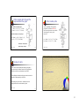
Errors
Errors are a part of our daily life.
Humans make errors in their thoughts, actions, and in
the products that might result from their
actions.
Errors, faults, failures
Errors occur wherever humans are involved in taking
actions and making decisions.
3
© Aditya P. Mathur 2005
These fundamental facts of human
existence make testing an essential
activity.
4
1
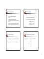
Error, faults, failures
Errors: Examples
Tester may make a mistake
In observing the behavior
© Aditya P. Mathur 2005
5
© Aditya P. Mathur 2005
6
Software quality
Static quality attributes: structured, maintainable,
testable code as well as the availability of correct and
complete documentation.
Software Quality
Dynamic quality attributes: software reliability,
correctness, completeness, consistency, usability, and
performance
7
© Aditya P. Mathur 2005
8
2
Software quality (contd.)
Software quality (contd.)
Completeness refers to the availability of all features listed
in the requirements, or in the user manual. An incomplete
software is one that does not fully implement all features
required.
Usability refers to the ease with which an application can be
used. This is an area in itself and there exist techniques for
usability testing. Psychology plays an important role in the
design of techniques for usability testing.
Consistency refers to adherence to a common set of
conventions and assumptions. For example, all buttons in the
user interface might follow a common color coding
convention. An example of inconsistency would be when a
database application displays the date of birth of a person in
the database in different formats ignoring user preference.
Performance refers to the time the application takes to
perform a requested task. It is considered as a non-functional
requirement. It is specified in terms such as ``This task must
be performed at the rate of X units of activity in one second
on a machine running at speed Y, having Z gigabytes of
memory."
© Aditya P. Mathur 2005
9
© Aditya P. Mathur 2005
10
Requirements, behavior, correctness
Requirements leading to two different programs:
Requirement 1: It is required to write a
program that inputs two integers and outputs the
maximum of these.
Requirements, input domain, behavior,
correctness, reliability
Requirement 2: It is required to write a
program that inputs a sequence of integers and outputs the
sorted version of this sequence.
11
© Aditya P. Mathur 2005
12
3
Requirements: Incompleteness
Requirements: Ambiguity
Suppose that program max is developed to satisfy Requirement 1.
The expected output of max when the input integers are 13 and 19
can be easily determined to be 19.
Suppose now that the tester wants to know if the two integers are to
be input to the program on one line followed by a carriage return, or
on two separate lines with a carriage return typed in after each
number. The requirement as stated above fails to provide an answer
to this question.
© Aditya P. Mathur 2005
13
Input domain (Input space)
Requirement 2 is ambiguous. It is not clear whether the input
sequence is to sorted in ascending or in descending order. The
behavior of sort program, written to satisfy this requirement, will
depend on the decision taken by the programmer while writing
sort.
© Aditya P. Mathur 2005
14
Input domain (Continued)
Modified Requirement 2:
It is required to write a program that inputs a
sequence of integers and outputs the integers in this sequence
sorted in either ascending or descending order. The order of
the output sequence is determined by an input request
character which should be ``A'' when an ascending sequence
is desired, and ``D'' otherwise.
The set of all possible inputs to a program P is known as the input
domain or input space, of P.
Using Requirement 1 above we find the input domain of max
to be the set of all pairs of integers where each element in the pair
integers is in the range -32,768 till 32,767.
While providing input to the program, the request character is
input first followed by the sequence of integers to be sorted;
the sequence is terminated with a period.
© Aditya P. Mathur 2005
15
© Aditya P. Mathur 2005
16
4
Input domain (Continued)
Valid/Invalid Inputs
Based on the above modified requirement, the input domain
for sort is a set of pairs. The first element of the pair is a
character. The second element of the pair is a sequence of
zero or more integers ending with a period.
The modified requirement for sort mentions that the
request characters can be ``A'' and ``D'', but fails to answer
the question ``What if the user types a different character ?’’
When using sort it is certainly possible for the user to type a
character other than ``A'' and ``D''. Any character other than
``A'’ and ``D'' is considered as invalid input to sort. The
requirement for sort does not specify what action it should
take when an invalid input is encountered.
© Aditya P. Mathur 2005
17
Correctness vs. Reliability
18
Correctness and Testing
Though correctness of a program is desirable, it is almost
never the objective of testing.
While correctness attempts to establish that the program is
error free, testing attempts to find if there are any errors in it.
Thus testing does not demonstrate that a program is error free.
To establish correctness via testing would imply testing a
program on all elements in the input domain. In most cases
that are encountered in practice, this is impossible to
accomplish.
Testing, debugging, and the error removal processes
together increase our confidence in the correct functioning
of the program under test.
Thus correctness is established via
mathematical proofs of programs.
© Aditya P. Mathur 2005
© Aditya P. Mathur 2005
19
© Aditya P. Mathur 2005
20
5
Software reliability: two definitions
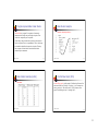
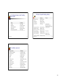
Operational profile
Software reliability [ANSI/IEEE Std 729-1983]: is the
probability of failure free operation of software over a
given time interval and under given conditions.
An operational profile is a numerical description of how a
program is used.
Consider a sort program which, on any given execution,
allows any one of two types of input sequences. Sample
operational profiles for sort follow.
Software reliability is the probability of failure free
operation of software in its intended environment.
© Aditya P. Mathur 2005
21
Operational profile
© Aditya P. Mathur 2005
© Aditya P. Mathur 2005
22
Operational profile
23
© Aditya P. Mathur 2005
24
6
Testing and debugging
Testing is the process of determining if a program has any
errors.
Testing, debugging, Verification
When testing reveals an error, the process used to determine
the cause of this error and to remove it, is known as debugging.
25
© Aditya P. Mathur 2005
26
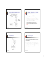
A test/debug cycle
Test plan
A test cycle is often guided by a test plan.
Example: The sort program is to be tested to meet the
requirements given earlier. Specifically, the following needs to
be done.
•
No
© Aditya P. Mathur 2005
Execute sort on at least two input sequences, one
with ``A'' and the other with ``D'' as request
characters.
Yes
27
© Aditya P. Mathur 2005
28
7
Test plan (contd.)
•
Execute the program on an empty input
sequence.
•
Test the program for robustness against
erroneous inputs such as ``R'' typed in as the request
character.
•
Test case/data
A test case is a pair consisting of test data to be input to
the program and the expected output. The test data is a
set of values, one for each input variable.
A test set is a collection of zero or more test cases.
Sample test case for sort:
All failures of the test program should be recorded in a
suitable file using the Company Failure Report Form.
© Aditya P. Mathur 2005
Test data: <''A'’ 12 -29 32 >
Expected output: -29 12 32
29
© Aditya P. Mathur 2005
Program behavior
30
Program behavior: Example
Can be specified in several ways: plain natural language, a
state diagram, formal mathematical specification, etc.
Consider a menu
driven application.
A state diagram specifies program states and how the
program changes its state on an input sequence.
inputs.
© Aditya P. Mathur 2005
31
© Aditya P. Mathur 2005
32
8
Program behavior: Example (contd.)
Behavior: observation and analysis
In the first step one observes the behavior.
In the second step one analyzes the observed behavior to
check if it is correct or not. Both these steps could be quite
complex for large commercial programs.
State
Diagram
The entity that performs the task of checking the
correctness of the observed behavior is known as an
oracle.
© Aditya P. Mathur 2005
33
© Aditya P. Mathur 2005
Oracle: Example
34
Oracle: Programs
Oracles can also be programs designed to check the behavior
of other programs.
For example, one might use a matrix multiplication program
to check if a matrix inversion program has produced the correct
output. In this case, the matrix inversion program inverts a given
matrix A and generates B as the output matrix.
© Aditya P. Mathur 2005
35
© Aditya P. Mathur 2005
36
9
Oracle: Construction
Testing and verification
Construction of automated oracles, such as the one to check
a matrix multiplication program or a sort program, requires
the determination of input-output relationship.
Program verification aims at proving the correctness of
programs by showing that it contains no errors. This is very
different from testing that aims at uncovering errors in a
program.
In general, the construction of automated oracles is a
complex undertaking.
Program verification and testing are best considered as
complementary techniques. In practice, one can shed program
verification, but not testing.
© Aditya P. Mathur 2005
37
© Aditya P. Mathur 2005
38
Testing and verification (contd.)
Testing is not a perfect technique in that a program might
contain errors despite the success of a set of tests.
Program representation: Control flow
graphs
Verification might appear to be perfect technique as it promises
to verify that a program is free from errors. However, the person
who verified a program might have made mistake in the
verification process; there might be an incorrect assumption on
the input conditions; incorrect assumptions might be made
regarding the components that interface with the program, and
so on.
© Aditya P. Mathur 2005
Verified and published programs have been shown
to be incorrect.
39
40
10
Program representation: Basic blocks
Basic blocks: Example
Example: Computing x raised to y
A basic block in program P is a sequence of consecutive
statements with a single entry and a single exit point. Thus
a block has unique entry and exit points.
Control always enters a basic block at its entry point and exits
from its exit point. There is no possibility of exit or a halt at any
point inside the basic block except at its exit point. The entry
and exit points of a basic block coincide when the block
contains only one statement.
© Aditya P. Mathur 2005
41
Basic blocks: Example (contd.)
42
Control Flow Graph (CFG)
Basic blocks
© Aditya P. Mathur 2005
© Aditya P. Mathur 2005
A control flow graph (or flow graph) G is defined as a finite set N of
nodes and a finite set E of edges. An edge (i, j) in E connects two
nodes ni and nj in N. We often write G= (N, E) to denote a flow
graph G with nodes given by N and edges by E.
43
© Aditya P. Mathur 2005
44
11
Control Flow Graph (CFG)
CFG Example
N={Start, 1, 2, 3, 4, 5, 6, 7,
8, 9, End}
In a flow graph of a program, each basic block becomes a node
and edges are used to indicate the flow of control between
blocks.
E={(Start,1), (1, 2), (1, 3), (2,4),
(3, 4), (4, 5), (5, 6), (6, 5),
(5, 7), (7, 8), (7, 9), (9,
End)}
Blocks and nodes are labeled such that block bi corresponds to
node ni. An edge (i, j) connecting basic blocks bi and bj implies
that control can go from block bi to block bj.
We also assume that there is a node labeled Start in N that has no
incoming edge, and another node labeled End, also in N, that has
no outgoing edge.
© Aditya P. Mathur 2005
45
CFG Example
46
Paths
Consider a flow graph G= (N, E). A sequence of k edges, k>0,
(e_1, e_2, … e_k) , denotes a path of length k through the flow
graph if the following sequence condition holds.
Same CFG with statements
removed.
N={Start, 1, 2, 3, 4, 5, 6, 7,
8, 9, End}
Given that np, nq, nr, and ns are nodes belonging to N,
and 0< i<k, if ei = (np, nq) and ei+1 = (nr, ns) then nq =
nr. }
E={(Start,1), (1, 2), (1, 3), (2,4),
(3, 4), (4, 5), (5, 6), (6, 5),
(5, 7), (7, 8), (7, 9), (9,
End)}
© Aditya P. Mathur 2005
© Aditya P. Mathur 2005
47
© Aditya P. Mathur 2005
48
12
Paths: sample paths through the
exponentiation flow graph
Paths: feasible paths
Two feasible and complete paths:
A path p through a flow graph for
program P is considered feasible if
there exists at least one test case which
when input to P causes p to be
traversed.
p1= ( Start, 1, 2, 4, 5, 6, 5, 7, 9, End)
p2= (Start, 1, 3, 4, 5, 6, 5, 7, 9, End)
Specified unambiguously using edges:
p1= ( (Start, 1), (1, 2), (2, 4), (4, 5), (5,
6), (6, 5), (5, 7), (7, 9), (9, End))
p1= ( Start, 1, 3, 4, 5, 6, 5, 7, 8, 9, End)
p2= (Start, 1, 1, 2, 4, 5, 7, 9, , End)
Bold edges: complete path.
© Aditya P. Mathur 2005
Dashed edges: subpath.
49
© Aditya P. Mathur 2005
50
Number of paths
There can be many distinct paths through a program. A
program with no condition contains exactly one path that
begins at node Start and terminates at node End.
Test generation
Each additional condition in the program can increases the
number of distinct paths by at least one.
Depending on their location, conditions can have a
multiplicative effect on the number of paths.
© Aditya P. Mathur 2005
51
52
13
Test generation
Test generation strategies
Any form of test generation uses a source document. In the
most informal of test methods, the source document resides
in the mind of the tester who generates tests based on a
knowledge of the requirements.
Model based: require that a subset of the requirements be
modeled using a formal notation (usually graphical). Models:
Finite State Machines, Timed automata, Petri nets, etc.
In most commercial environments, the process is a bit more
formal. The tests are generated using a mix of formal and
informal methods directly from the requirements document
serving as the source. In more advanced test processes,
requirements serve as a source for the development of formal
models.
Specification based: require that a subset of the requirements
be modeled using a formal mathematical notation. Examples:
B, Z, and Larch.
© Aditya P. Mathur 2005
Code based: generate tests directly from the code.
53
© Aditya P. Mathur 2005
54
Test generation strategies (Summary)
Strings and languages
© Aditya P. Mathur 2005
55
56
14
Strings
Alphabet
Strings play an important role in testing. A string serves as
a test input. Examples: 1011; AaBc; “Hello world”.
A collection of symbols is known as an alphabet. We use
an upper case letter such as X and Y to denote alphabets.
A collection of strings also forms a language. For example, a set
of all strings consisting of zeros and ones is the language of
binary numbers. In this section we provide a brief introduction to
strings and languages.
© Aditya P. Mathur 2005
Though alphabets can be infinite, we are concerned only with
finite alphabets. For example, X={0, 1} is an alphabet consisting
of two symbols 0 and 1. Another alphabet is Y={dog, cat, horse,
lion}that consists of four symbols ``dog", ``cat", ``horse", and
``lion".
57
Strings over an Alphabet
© Aditya P. Mathur 2005
58
String concatenation
A string over an alphabet X is any sequence of zero or
more symbols that belong to X. For example, 0110 is a
string over the alphabet {0, 1}. Also, dog cat dog dog lion
is a string over the alphabet {dog, cat, horse, lion}.
Let s1 and s2 be two strings over alphabet X. We write s1.s2 to
denote the concatenation of strings s1 and s2.
We will use lower case letters such as p, q, r to denote strings. The
length of a string is the number of symbols in that string. Given a string
s, we denote its length by |s|. Thus |1011|=4 and |dog cat dog|=3. A
string of length 0, also known as an empty string, is denoted by ε.
For example, given the alphabet X={0, 1}, and two strings 011
and 101 over X, we obtain 011.101=011101. It is easy to see that |
s1.s2|=|s1|+|s2|. Also, for any string s, we have s. ε =s and ε.s=s.
Note that ε denotes an empty string.
© Aditya P. Mathur 2005
59
© Aditya P. Mathur 2005
60
15
Languages
Regular expressions
Given a finite alphabet X, the following are regular expressions
over X:
A set L of strings over an alphabet X is known as a language. A
language can be finite or infinite.
If a belongs to X, then a is a regular expression that denotes the set
{a}.
The following sets are finite languages over the binary alphabet
{0, 1}:
Let r1 and r2 be two regular expressions over the alphabet X that
denote, respectively, sets L1 and L2. Then r1.r2 is a regular
expression that denotes the set L1.L2.
∅: The empty set
{ε}: A language consisting only of one string of length zero
{00, 11, 0101}: A language containing three strings
© Aditya P. Mathur 2005
61
© Aditya P. Mathur 2005
62
Regular expressions (contd.)
If r is a regular expression that denotes the set L then r+ is a
regular expression that denotes the set obtained by concatenating
L with itself one or more times also written as L+ Also, r* known
as the Kleene closure of r, is a regular expression. If r denotes the
set L then r* denotes the set {ε}∪ L+.
Embedded systems and Finite State
Machines (FSMs)
If r1 and r2 are regular expressions that denote, respectively, sets L1
and L2, then r1 | r2 is also a regular expression that denotes the set
L1 ∪ L2.
© Aditya P. Mathur 2005
63
64
16
Embedded systems
Specifying embedded systems
Many real-life devices have computers embedded in them.
For example, an automobile has several embedded
computers to perform various tasks, engine control being
one example. Another example is a computer inside a toy
for processing inputs and generating audible and visual
responses.
An embedded computer often receives inputs from its
environment and responds with appropriate actions. While
doing so, it moves from one state to another.
The response of an embedded system to its inputs depends on its
current state. It is this behavior of an embedded system in
response to inputs that is often modeled by a finite state
machine (FSM).
Such devices are also known as embedded systems. An
embedded system can be as simple as a child's musical keyboard
or as complex as the flight controller in an aircraft. In any case,
an embedded system contains one or more computers for
processing inputs.
© Aditya P. Mathur 2005
65
FSM: Actions with state transitions
© Aditya P. Mathur 2005
66
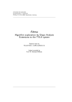
FSM: Formal definition
An FSM is a quintuple: (X, Y, Q, q0, δ, O), where:,
Machine to convert a sequence of decimal digits to an integer:
X is a finite set of input symbols also known as the input
alphabet.
Y is a finite set of output symbols also known as the output
alphabet,
Q is a finite set states,
(a) Notice ADD, INIT, ADD,OUT actions.
(b) INIT: Initialize num. ADD: Add to num. OUT: Output num.
© Aditya P. Mathur 2005
67
© Aditya P. Mathur 2005
68
17
FSM: Formal definition (contd.)
State diagram representation of FSM
A state diagram is a directed graph that contains nodes
representing states and edges representing state
transitions and output functions.
q0 in Q is the initial state,
δ: Q x X→ Q is a next-state or state transition function, and
Each node is labeled with the state it represents. Each directed
edge in a state diagram connects two states. Each edge is labeled
i/o where i denotes an input symbol that belongs to the input
alphabet X and o denotes an output symbol that belongs to the
output alphabet O. i is also known as the input portion of the
edge and o its output portion.
O: Q x X→ Y is an output function.
In some variants of FSM more than one state could be
specified as an initial state. Also, sometimes it is
convenient to add F⊆ Q as a set of final or accepting
states while specifying an FSM.
© Aditya P. Mathur 2005
69
Properties of FSM
© Aditya P. Mathur 2005
Properties of FSM: Equivalence
Completely specified: An FSM M is said to be completely
specified if from each state in M there exists a transition for
each input symbol.
V-equivalence: Let M1=(X, Y, Q1, m10, T1, O1) and M2=(X, Y,
Q2, m20, T2, O2) be two FSMs. Let V denote a set of nonempty strings over the input alphabet X i.e. V⊆ X+.
Strongly connected: An FSM M is considered strongly
connected if for each pair of states (qi qj) there exists an input
sequence that takes M from state qi to qj.
Let qi and qj, i≠ j, be the states of machines M1 and M2,
respectively. qi and qj are considered V-equivalent if O1(qi,
s)=O2(qj, s) for all s in V.
© Aditya P. Mathur 2005
70
71
© Aditya P. Mathur 2005
72
18
Properties of FSM: Distinguishable
Properties of FSM: Machine Equivalence
Stated differently, states qi and qj are considered V-equivalent
if M1 and M2 , when excited in states qi and qj, respectively,
yield identical output sequences.
Machine equivalence: Machines M1 and M2 are said to be
equivalent if (a) for each state σ in M1 there exists a state σ ' in
M2 such that σ and σ ' are equivalent and (b) for each state σ in
M2 there exists a state σ ' in M1 such that σ and σ ' are
equivalent.
States qi and qj are said to be equivalent if O1(qi, r)=O2(qj, r)
for any set V. If qi and qj are not equivalent then they are said to
be distinguishable. Thus machines M1 and M2 could be the
same machine.
* This definition of equivalence also applies to states within a
machine.
© Aditya P. Mathur 2005
Machines that are not equivalent are considered distinguishable.
Minimal machine: An FSM M is considered minimal if the
number of states in M is less than or equal to any other FSM
equivalent to M.
73
© Aditya P. Mathur 2005
Properties of FSM: k-equivalence
(contd.)
Properties of FSM: k-equivalence
k-equivalence: Let M1=(X, Y, Q1, m10, T1, O1) and M2=(X, Y,
Q2, m20, T2, O2) be two FSMs.
States that are not k-equivalent are considered k-distinguishable.
States qiε Q1 and qjε Q2 are considered k-equivalent if, when
excited by any input of length k, yield identical output
sequences.
It is also easy to see that if two states are k-distinguishable
for any k>0 then they are also distinguishable for any n≥ k.
If M1 and M2 are not k-distinguishable then they are said to
be k-equivalent.
© Aditya P. Mathur 2005
74
75
© Aditya P. Mathur 2005
76
19
Example: Completely specified machine
Types of software testing
© Aditya P. Mathur 2005
78
77
C1: Source of test generation
Types of testing
One possible classification is based on the following four
classifiers:
C1: Source of test generation.
C2: Lifecycle phase in which testing takes place
C3: Goal of a specific testing activity
C4: Characteristics of the artifact under test
© Aditya P. Mathur 2005
79
© Aditya P. Mathur 2005
80
20
C3: Goal of specific testing activity
C2: Lifecycle phase in which testing
takes place
© Aditya P. Mathur 2005
81
© Aditya P. Mathur 2005
82
C4: Artifact under test
© Aditya P. Mathur 2005
83
21