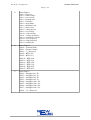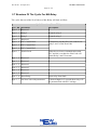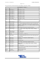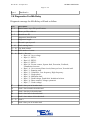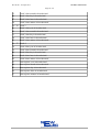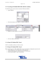
1
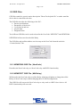
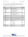
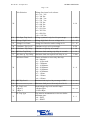
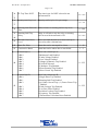
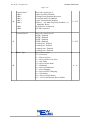
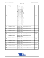
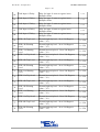
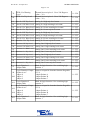
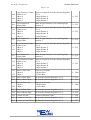
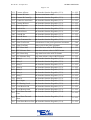
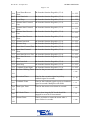
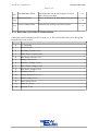
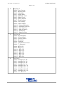
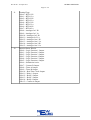
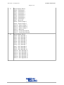
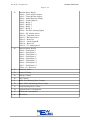
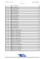
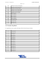
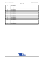
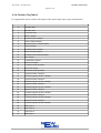
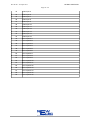
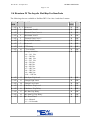
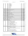
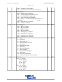
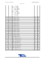
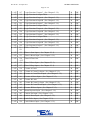
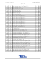
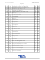
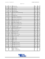
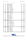
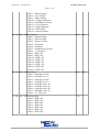
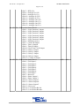
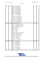
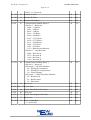
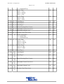
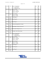
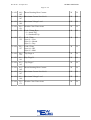
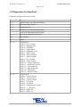
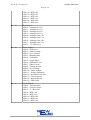
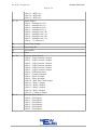
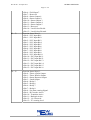
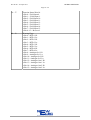
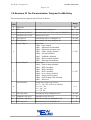
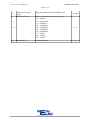
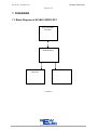
NC-MK1-PROFI-DP1
Rev 2E-00 – 02 April 2013
Page 1 / 68
NewCode
Profibus DPV1
Communication Module
User Manual
NC-MK1-PROFI-DP1
Version 2E-01
(NE_NC-MK1-PROFI-DP1_MAN_02_13_E-01)
2 April 2013
NC-MK1-PROFI-DP1
Rev 2E-00 – 02 April 2013
Page 2 / 68
Content
Page
1. ABSTRACT ........................................................................................................................... 3
2. SPECIFICATIONS................................................................................................................. 4
2.1 Technical Specifications of NC-MK1-PROFI-DP1 ......................................................... 4
2.2 GSD Files ......................................................................................................................... 5
2.2.1 NEWEF880 GSD File ( NewCode ) ......................................................................... 5
2.2.2 NEWEF877 GSD File ( MA-Relay ) ........................................................................ 5
2.3 Structure Of The Parameterization Telegram For NewCode ........................................... 6
2.3.1 NewCode Cyclic Data Of Actual Values................................................................. 16
2.3.2 Function Flag Table 1.............................................................................................. 23
2.3.3 Function Flag Table 2.............................................................................................. 27
2.3.4 Function Flag Table 3.............................................................................................. 29
2.4 Structure Of The Acyclic Slot Map For NewCode ........................................................ 31
2.5 Diagnostics For NewCode ............................................................................................. 48
2.6 Structure Of The Parametrization Telegram For MA-Relay .......................................... 53
2.7 Structure Of The Cyclic For MA-Relay......................................................................... 55
2.8 Diagnostics For MA-Relay ............................................................................................ 57
3. DEFINITIONS AND TERMINOLOGY ............................................................................. 59
4. FUNCTIONAL DESCRIPTION.......................................................................................... 60
5. OPERATING INSTRUCTIONS.......................................................................................... 61
5.1 Getting Started................................................................................................................ 61
5.1.1 Setting Up The NC-MK1-PROFI-DP1 ................................................................... 61
5.1.2 Installing Of NC-MK1-PROFI-DP1 GSD File STEP 7.......................................... 61
5.1.3 Installing Of NC-MK1-PROFI-DP1 GSD File ProfiSim ....................................... 63
5.1.4 Setup Of Profibus DPV1 Class 1 ............................................................................ 63
5.1.5 Setup Of Profibus DPV1 Class 2 ............................................................................ 63
5.2 Monitoring Diagnostic On Front-End ............................................................................ 65
6. ID NUMBER REGISTRATION FORM.............................................................................. 66
7. DIAGRAMS......................................................................................................................... 68
7.1 Block Diagram of NC-MK1-PROFI-DP1...................................................................... 68
NC-MK1-PROFI-DP1
Rev 2E-00 – 02 April 2013
Page 3 / 68
1. ABSTRACT
The NC-MK1-PROFI-DP1 (NewCode Profibus DPV1) acts as a translator between the
Profibus SCADA and the NewCode. It is advisable to read the NewCode user manual, as
some of the topics will require knowledge on the NewCode. It is also advisable to have
knowledge on profibus. Information on profibus can be found at the web site
www.profibus.com.
The communication protocol between the NC-MK1-PROFI-DP1 and SCADA is Profibus
DPV1 class 1 and class 2. Communication protocol between the NC-MK1-PROFI-DP1 and
the NewCode is a CHI proprietary protocol. Enabling the PLC to communicate with the
NewCode via Profibus DPV1.
NC-MK1-PROFI-DP1
Rev 2E-00 – 02 April 2013
Page 4 / 68
2. SPECIFICATIONS
2.1 Technical Specifications of NC-MK1-PROFI-DP1
General Data
NC-MK1PROFI-DP0
Mounting Positions
Allowed Ambient Temperature
Humidity
Power Supply
Consumption
Communication Mediums
Protocol
Baud Rate
Cable Length @ Baud Rate
Profibus
Termination Resistor
(Termination resistors must be
connected at the beginning and
end of bus)
Type
LED Indications
Indication
Lights
Mounted inside of NewCode.
Operation : 0 ºC to +60 ºC
< 87%
+5Vdc
100 mA
Profibus
I2C
Profibus DPV1
9600 bit/s to 12 Mbit/s
1200 m @ 9600 bit/s to 45450 bit/s
1000 m @93.75Kbit/s to 187.5Kbit/s
400 m @ 500 Kbit/s
200 m @ 1.5 Mbit/s
100 m @ 3 Mbit/s to 12 Mbit/s
220 Ohm.
Light Emitting Diode (LED)
SCADA Communication
Address Of Module
◦ Green Flash = 1
◦ Red Flash = 10
◦ Orange Flash = 100
◦ Orange Solid = I2C Error
◦ Red Solid = VPC Error
NC-MK1-PROFI-DP1
Rev 2E-00 – 02 April 2013
Page 5 / 68
2.2 GSD Files
GSD files stands for generic station description. These files help the PLC to under stand the
device that is connected to the bus.
The GSD file describes the following to the PLC:
• Device specifications.
• Parameters of the device.
• Cyclic data in and out.
• Acyclic data.
• Diagnostic data.
Two different GSD files can be used to describe the NewCode. NEWEF877 and NEWEF880.
NEWEF880 will not work on the MA-Relay.
The GSD files and profibus address can be setup on the NewCode frontend under the
“Comm+Statistic” tab.
2.2.1 NEWEF880 GSD File ( NewCode )
Describes the NewCode relay as a NewCode relay with DPV1 functionality.
2.2.2 NEWEF877 GSD File ( MA-Relay )
Will describe the NewCode relay as a MA-Relay. Allowing old plants to change there MARelays to NewCode relays without changing there SCADA configurations.
This GSD file will convert the NewCode relay to only work as a DPV0 slave device. All
DPV1 functionality will not work.
NC-MK1-PROFI-DP1
Rev 2E-00 – 02 April 2013
Page 6 / 68
2.3 Structure Of The Parameterization Telegram For NewCode
The parameterization telegram data will look as follow:
Byte Parameter Name
Addr
Description
0 ~ 2 DPV1 Selection
Profibus DPV1 settings.
3
Set
CM-Settings
• Bit 0
• Bit 1
• Bit 2
• Bit 7
Communication module settings.
• Overwrite Relay Settings.
• Overwrite Relay Logic Control.
• Overwrite Relay Starter Logic.
• Fail Safe Enabled.
Cyclic Dout Amount
Cyclic amount of bytes from PLC to NewCode.
• Byte 1 and 2 is PLC control byte.
• Byte 3 for analogue 1 out.
• Byte 4 for analogue 2 out.
1~4
Cyclic amount of words from NewCode to PLC.
1~6
Pointer to NewCode Cyclic Actual Values (2.3.1)
0~255
4
5
Range
Cyclic Din Amount
6 ~ 11 Word In Ptr 1~6
12
Maximum Load 0
Maximum load setting for low speed in percentage.
10~100
13
Thermal Curve Class 0
Thermal class model selected for low speed in sec.
5~45
14
Maximum Load 1
Maximum load setting for high speed in %.
15
Thermal Curve Class 1
Thermal class model selected for high speed in sec.
5~45
Relay Modal
Modal number of the relay
• 0 = NC 1
• 1 = NC 5
• 2 = NC 25
• 3 = NC 50
• 4 = NC 100
• 5 = NC 300
0~4
16
17~18 CT Primary
19
CT Secondary
Primary CT ratio
Secondary CT Ratio
10~100
1 ~ 1000
1~9
NC-MK1-PROFI-DP1
Rev 2E-00 – 02 April 2013
Page 7 / 68
Volt Selection
20
Voltage line input level selector.
• 0 = 110 Vac.
• 1 = 380 Vac.
• 2 = 400 Vac.
• 3 = 525 Vac.
• 4 = 550 Vac.
• 5 = 680 Vac.
• 6 = 950 Vac.
• 7 = 1K1 Vac.
• 8 = 3K3 Vac.
• 9 = 6K6 Vac.
• 10 = 11K Vac.
0~10
21
Volt Sym. Trip Level
Voltage symmetric trip level in percentage.
1~100
22
Voltage High Limit
Voltage high limit for over voltage in %.
0 ~ 15
23
Voltage Low Limit
Voltage low limit for under voltage in %.
0 ~ 15
24
Unbalance Trip Level
Unbalance trip level in percentage.
0~50
25
Unbalance Trip Delay
Unbalance trip delay in seconds.
1~10
26
ML Run Trip Delay
Minimum load running trip delay in seconds.
1~10
27
ML Start up Trip Delay Minimum load start up hold off delay in sec.
1~200
ML Reset Timer.
28
Time it will take to reset relay after trip.
• 0 = Manual.
• 1 = 10 Seconds.
• 2 = 5 Minutes.
• 3 = 10 Minutes.
• 4 = 20 Minutes.
• 5 = 30 Minutes.
• 6 = 45 Minutes.
• 7 = 1 Hour.
• 8 = 3 Hours.
• 9 = 6 Hours.
0~9
29
ML Trip Level.
Minimum load trip level in percentage of MLC.
10 ~ 100
30
ML Power Factor Trip Level
Minimum load power factor trip level in %.
10 ~ 100
31
~
32
EL Trip Level
• Byte 0
• Byte 1
Earth leakage trip level in milli Amps.
• Higher Byte.
• Lower Byte.
100 ~ 999
EL Trip Type
Trip must be instantaneous or inverse define
minimum time.
• 0 = INST.
• 1 = IDMT
33
0~1
NC-MK1-PROFI-DP1
Rev 2E-00 – 02 April 2013
Page 8 / 68
34
~
35
EL Trip Time INST
36
~
37
Running Stall Trip Level
38
39
~
40
Trip time in ms for INST selected in ms
incremental 50.
100 ~ 1000
Running stall trip level in percentage.
110 ~ 300
Running Stall Hold Off Hold off time for running stall to trip in sec.
Time
0 ~ 200
Running Stall Trip
Delay
Delay it will take to trip the relay on running
stall in ms with incremental of 50.
41
Thermal Class Reset
Level
Reset level that thermal level must build up to
reset relay after a thermal trip.
42
Starts Per Hour
Starts that can be attempted in a hour.
1 ~ 60
43
Consecutive Starts
Starts that can be taken after a start failed.
1~3
44
Control Byte A
• Bit 0
• Bit 1
• Bit 2
• Bit 3
• Bit 4
• Bit 5
• Bit 6
• Bit 7
NewCode control byte A.
• Minimum Load Enabled.
• Under Voltage Enabled.
• Over Voltage Enabled.
• Voltage Symmetric Trip Enabled.
• Fail Safe Selected.
• Unbalance Trip Enabled.
• Phase Rotation Trip Enabled.
• Short Circuit Trip Enabled.
0 ~ 255
Control Byte B
• Bit 0
• Bit 1
• Bit 2
NewCode control byte B.
• Single Phase Trip Enabled.
• Running Stall Trip Enabled.
• (0) Under Current Trip / (1) Power Factor Trip
Enabled.
• Earth Leakage Trip Enabled.
• Low Pass Filter Enabled.
• Isolation Lockout Trip Enabled.
• Frequency Trip Enabled.
• Thermal Auto Calculate Reset Enabled.
0 ~ 255
45
• Bit 3
• Bit 4
• Bit 5
• Bit 6
• Bit 7
100 ~ 2000
NC-MK1-PROFI-DP1
Rev 2E-00 – 02 April 2013
Page 9 / 68
46
Control Byte C
• Bit 0
• Bit 1
• Bit 2
• Bit 3
• Bit 4
• Bit5
• Bit6
Control Byte D
47
Starter Type
48
NewCode control byte C.
• Starts Per Hour Enabled.
• Voltage Phase Rotation Reversed.
• Vectorial Stall Trip Enabled.
• Auto Thermal Reset Enabled.
• Relay 1 = (0) Main Trip Relay Enabled / (1)
Mappable Relay.
• External I/O Connected.
• FLED Connected
0 ~ 255
NewCode control byte D.
• RTD 1 Enabled.
• RTD 2 Enabled.
• RTD 3 Enabled.
• RTD 4 Enabled.
• Analog In 1 Enabled .
• Analog In 2 Enabled.
• Analog Out 1 Enabled
• Analog Out 2 Enabled
0 ~ 255
Type of starter logic:
• 0 = Protection.
• 1 = Direct On Line.
• 2 = Reversal Direct On Line.
• 3 = Star-Delta.
• 4 = Reversal Star-Delta.
• 5 = Dahlander.
• 6 = Reversal Dahlander.
• 7 = Pole Changing.
• 8 = Reversal Pole Changing.
• 9 = Soft Starter.
• 10 = Reversal Soft Starter.
• 11 = Oil Circuit Breaker Direct Online.
0 ~ 11
NC-MK1-PROFI-DP1
Rev 2E-00 – 02 April 2013
Page 10 / 68
RTD Type
RTD Type
Bit 0 ~ 1 = RTD1
00 = PT100
01 = PT1000
10 = PTC
11 = NTC
Bit 2 ~ 4 = RTD2
00 = PT100
01 = PT1000
10 = PTC
11 = NTC
Bit 5 ~ 6 = RTD3
00 = PT100
01 = PT1000
10 = PTC
11 = NTC
Bit 7 ~ 8 = RTD 4
00 = PT100
01 = PT1000
10 = PTC
11 = NTC
0 ~ 255
Field Input 1 Delay
Delay for input 1 state to register in ms.
Multiplier 50ms
0 ~ 40
Field Input 2 Delay
Delay for input 2 state to register in ms.
Multiplier 50ms
0 ~ 40
Field Input 3 Delay
Delay for input 3 state to register in ms.
Multiplier 50ms
0 ~ 40
Field Input 4 Delay
Delay for input 4 state to register in ms.
Multiplier 50ms
0 ~ 40
Field Input 5 Delay
Delay for input 5 state to register in ms.
Multiplier 50ms
0 ~ 40
Field Input 6 Delay
Delay for input 6 state to register in ms.
Multiplier 50ms
0 ~ 40
Field Input 7 Delay
Delay for input 7 state to register in ms.
Multiplier 50ms
0 ~ 40
Field Input 8 Delay
Delay for input 8 state to register in ms.
Multiplier 50ms
0 ~ 40
Field Input 9 Delay
Delay for input 9 state to register in ms.
Multiplier 50ms
0 ~ 40
Field Input 10 Delay
Delay for input 10 state to register in ms.
Multiplier 50ms
0 ~ 40
49
50
51
52
53
54
55
56
57
58
59
NC-MK1-PROFI-DP1
Rev 2E-00 – 02 April 2013
Page 11 / 68
Field Input 11 Delay
Delay for input 11 state to register in ms.
Multiplier 50ms
0 ~ 40
Field Input 12 Delay
Delay for input 12 state to register in ms.
Multiplier 50ms
0 ~ 40
Field Input 13 Delay
Delay for input 13 state to register in ms.
Multiplier 50ms
0 ~ 40
Field Input 14 Delay
Delay for input 14 state to register in ms.
Multiplier 50ms
0 ~ 40
Field Input 15 Delay
Delay for input 15 state to register in ms.
Multiplier 50ms
0 ~ 40
RTD 1 Hi Trip Level
Thermal high trip level. -30 to 220 Degrees.
(value – 30 )
0 ~ 250
66
RTD 1 Hi Warning
Level
Thermal high trip level. -30 to 220 Degrees.
(value – 30 )
0 ~ 250
67
RTD 1 Lo Warning
Level
Thermal lower trip level. -30 to 220 Degrees.
(value – 30 )
0 ~ 250
RTD 1 Lo Trip Level
Thermal lower trip level. -30 to 220 Degrees.
(value – 30 )
0 ~ 250
RTD 2 Hi Trip Level
Thermal high trip level. -30 to 220 Degrees.
(value – 30 )
0 ~ 250
70
RTD 2 Hi Warning
Level
Thermal high trip level. -30 to 220 Degrees.
(value – 30 )
0 ~ 250
71
RTD 2 Lo Warning
Level
Thermal lower trip level. -30 to 220 Degrees.
(value – 30 )
0 ~ 250
RTD 2 Lo Trip Level
Thermal lower trip level. -30 to 220 Degrees.
(value – 30 )
0 ~ 250
RTD 3 Hi Trip Level
Thermal high trip level. -30 to 220 Degrees.
(value – 30 )
0 ~ 250
74
RTD 3 Hi Warning
Level
Thermal high trip level. -30 to 220 Degrees.
(value – 30 )
0 ~ 250
75
RTD 3 Lo Warning
Level
Thermal lower trip level. -30 to 220 Degrees.
(value – 30 )
0 ~ 250
RTD 3 Lo Trip Level
Thermal lower trip level. -30 to 220 Degrees.
(value – 30 )
0 ~ 250
RTD 4 Hi Trip Level
Thermal high trip level. -30 to 220 Degrees.
(value – 30 )
0 ~ 250
RTD 4 Hi Warning
Level
Thermal high trip level. -30 to 220 Degrees.
(value – 30 )
0 ~ 250
60
61
62
63
64
65
68
69
72
73
76
77
78
NC-MK1-PROFI-DP1
Rev 2E-00 – 02 April 2013
Page 12 / 68
RTD 4 Lo Warning
Level
Thermal lower trip level. -30 to 220 Degrees.
(value – 30 )
0 ~ 250
RTD 4 Lo Trip Level
Thermal lower trip level. -30 to 220 Degrees.
(value – 30 )
0 ~ 250
81
Ana In 1 Hi Trip Level
Analog In 1 high trip level count.
0 ~ 255
82
Ana In 1 Hi Warn Level Analog In 1 high warning level count.
0 ~ 255
83
Ana In 1 Lo Warn Level Analog In 1 lower warning level count.
0 ~ 255
84
Ana In 1 Lo Trip Level Analog In 1 lower trip level count.
0 ~ 255
85
Ana In 2 Hi Trip Level
0 ~ 255
86
Ana In 2 Hi Warn Level Analog In 2 high warning level count.
0 ~ 255
87
Ana In 2 Lo Warn Level Analog In 2 lower warning level count.
0 ~ 255
88
AnaOut 2 Lo Trip Level Analog In 2 lower trip level count.
0 ~ 255
89
AnaOut 1 Hi Trip Level
Analog Out 1 high trip level count.
0 ~ 255
90
AnaOut 1 Hi Warn Level
Analog Out 1 high warning level count.
0 ~ 255
91
AnaOut 1 Lo Warn Level
Analog Out 1 lower warning level count.
0 ~ 255
92
AnaOut 1 Lo Trip Level
Analog Out 1 lower trip level count.
0 ~ 255
93
AnaOut 2 Hi Trip Level
Analog Out 2 high trip level count.
0 ~ 255
94
AnaOut 2 Hi Warn Level
Analog Out 2 high warning level count.
0 ~ 255
95
AnaOut 2 Lo Warn Level
Analog Out 2 lower warning level count.
0 ~ 255
96
AnaOut 2 Lo Trip Level
Analog Out 2 lower trip level count.
0 ~ 255
97
Logic Function 1
Output Table
Mask for logic function 1 for switching logic
function 1.
0 ~ 255
Points to a input bit from the function flag table
(2.3.2)
• Input Pointer A
• Input Pointer B
• Input Pointer C
0 ~ 255
Mask for logic function 1 for switching logic
function 2.
0 ~ 255
Points to a input bit from the function flag table
(2.3.2)
• Input Pointer A
• Input Pointer B
• Input Pointer C
0 ~ 255
Mask for logic function 1 for switching logic
function 3.
0 ~ 255
79
80
Logic Function 1 Input
98 Pointer A to C
• Byte 0
~
100 • Byte 1
• Byte 2
101
Logic Function 2
Output Table
Logic Function 2 Input
102 Pointer A to C
• Byte 0
~
104 • Byte 1
• Byte 2
105
Logic Function 3
Output Table
Analog In 2 high trip level count.
NC-MK1-PROFI-DP1
Rev 2E-00 – 02 April 2013
Page 13 / 68
Logic Function 3 Input
106 Pointer A to C
• Byte 0
~
108 • Byte 1
• Byte 2
Points to a input bit from the function flag table
(2.3.2)
• Input Pointer A
• Input Pointer B
• Input Pointer C
0 ~ 255
109
Logic Function 4
Output Table
Mask for logic function 1 for switching logic
function 4.
0 ~ 255
110
~
112
Logic Function 4 Input
Pointer A to C
• Byte 0
• Byte 1
• Byte 2
Points to a input bit from the function flag table
(2.3.2)
• Input Pointer A
• Input Pointer B
• Input Pointer C
0 ~ 255
113
Logic Function 5
Output Table
Mask for logic function 1 for switching logic
function 5.
0 ~ 255
114
~
116
Logic Function 5 Input
Pointer A to C
• Byte 0
• Byte 1
• Byte 2
Points to a input bit from the function flag table
(2.3.2)
• Input Pointer A
• Input Pointer B
• Input Pointer C
0 ~ 255
117
Logic Function 6
Output Table
Mask for logic function 1 for switching logic
function 6.
0 ~ 255
Logic Function 6 Input
118 Pointer A to C
• Byte 0
~
120 • Byte 1
• Byte 2
Points to a input bit from the function flag table
(2.3.2)
• Input Pointer A
• Input Pointer B
• Input Pointer C
0 ~ 255
121 Timer A Time Out
~
• Byte 0
122 • Byte 1
Time out in seconds.
• Higher Byte.
• Lower Byte.
1 ~ 3000
123 Timer A Start Input
Bit from the function flag table (2.3.2) .
0 ~ 255
124 Timer A Reset Input
Bit from the function flag table (2.3.2).
0 ~ 255
125 Timer B Time Out
~
• Byte 0
126 • Byte 1
Time out in seconds.
• Higher Byte.
• Lower Byte.
1 ~ 3000
127 Timer B Start Input
Bit from the function flag table (2.3.2).
0 ~ 255
128 Timer B Reset Input
Bit from the function flag table (2.3.2).
0 ~ 255
129 Counter A Limit
Counters maximum value.
1 ~ 250
130 Counter A Count Up
Bit from the function flag table (2.3.2).
0 ~ 255
131 Counter A Count Down Bit from the function flag table (2.3.2).
0 ~ 255
NC-MK1-PROFI-DP1
Rev 2E-00 – 02 April 2013
Page 14 / 68
132 Counter A Reset
Bit from the function flag table (2.3.2).
0 ~ 255
133 Counter B Limit
Counters maximum value.
1 ~ 250
134 Counter B Count Up
Bit from the function flag table (2.3.2).
0 ~ 255
135 Counter B Count Down
Bit from the function flag table (2.3.2).
0 ~ 255
136 Counter B Reset
Bit from the function flag table (2.3.2).
0 ~ 255
137 Status Reporter
Bit from the function flag table (2.3.2).
0 ~ 255
138 Latch A Set
Bit from the function flag table (2.3.2).
0 ~ 255
139 Latch A Reset
Bit from the function flag table (2.3.2).
0 ~ 255
140 Latch B Set
Bit from the function flag table (2.3.2).
0 ~ 255
141 Latch B Reset
Bit from the function flag table (2.3.2).
0 ~ 255
142 Pulse Generator Set
Bit from the function flag table (2.3.2).
0 ~ 255
143 Pulse Gen Period
Period timer for the pulse generator in minutes.
1 ~ 240
144 Pulse Gen Duty
Duty cycle for the pulse genarator.
1 ~ 100
145 RTC Hour Start
Start time hour value in BCD format.
0 ~ 255
146 RTC Minutes Start
Start time minutes value in BCD format.
0 ~ 255
147 RTC Hour Stop
Stop time hour value in BCD format.
0 ~ 255
148 RTC Minutes Stop
Stop time minutes value in BCD format.
0 ~ 255
149 Relay 1
Bit from the function flag table (2.3.2).
0 ~ 255
150 Relay 2
Bit from the function flag table (2.3.2).
0 ~ 255
151 Relay 3
Bit from the function flag table (2.3.2).
0 ~ 255
152 Relay 4
Bit from the function flag table (2.3.2).
0 ~ 255
153 Relay 5
Bit from the function flag table (2.3.2).
0 ~ 255
154 Relay 6
Bit from the function flag table (2.3.2).
0 ~ 255
155 Relay 7
Bit from the function flag table (2.3.2).
0 ~ 255
156 Relay 8
Bit from the function flag table (2.3.2).
0 ~ 255
157 Reset Input
Bit from the function flag table (2.3.2).
0 ~ 255
158 TC Warning Level
Bit from the function flag table (2.3.2).
0~255
159 Local Remote lsb
Bit from the function flag table (2.3.3).
0 ~ 255
160 Local Remote msb
Bit from the function flag table (2.3.3).
0 ~ 255
161
Local Start Forward
Fast
Bit from the function flag table (2.3.4).
162
Local Start Forward
Slow
Bit from the function flag table (2.3.4).
163 Local Start Reverse Fast Bit from the function flag table (2.3.4).
0 ~ 255
0 ~ 255
0 ~ 255
NC-MK1-PROFI-DP1
Rev 2E-00 – 02 April 2013
Page 15 / 68
164
Local Start Reverse
Slow
Bit from the function flag table (2.3.4).
0 ~ 255
165 Local Interlock
Bit from the function flag table (2.3.4).
0 ~ 255
166 Local Stop
Bit from the function flag table (2.3.4).
0 ~ 255
167
Remote Start Forward
Fast
Bit from the function flag table (2.3.4).
168
Remote Start Forward
Slow
Bit from the function flag table (2.3.4).
169
Remote Start Reverse
Fast
Bit from the function flag table (2.3.4).
170
Remote Start Reverse
Slow
Bit from the function flag table (2.3.4).
0 ~ 255
0 ~ 255
0 ~ 255
0 ~ 255
171 Remote Interlock
Bit from the function flag table (2.3.4).
0 ~ 255
172 Remote Stop
Bit from the function flag table (2.3.4).
0 ~ 255
173 Auto Start Forward Fast Bit from the function flag table (2.3.4).
0 ~ 255
174
Auto Start Forward
Slow
Bit from the function flag table (2.3.4).
175 Auto Start Reverse Fast Bit from the function flag table (2.3.4).
176
Auto Start Reverse
Slow
Bit from the function flag table (2.3.4).
0 ~ 255
0 ~ 255
0 ~ 255
177 Auto Interlock
Bit from the function flag table (2.3.4).
0 ~ 255
178 Auto Stop
Bit from the function flag table (2.3.4).
0 ~ 255
179 Feedback Signal Input
Bit from the function flag table (2.3.4).
0 ~ 255
180 Pre Start Warning Timer Time for the pre start siren in seconds.
~
181
182
183
Execution Timer
Time for the execution signal to pick up
feedback signal in seconds.
Feedback Timer
Time for the feedback signal to pick up feedback
signal in seconds. Multiplier with 50ms
184 Back Spin Timer
~
185
186
DC Break Timer
187 Restart Timer
~
188
1 ~ 3000
1 ~ 10
1 ~ 40
Time for the motor to run down in seconds.
1 ~ 3000
Time to how long the DC break should be
engaged in ms with 50 incremental.
Time it will take to restart the motor after a
power failure in seconds.
1 ~ 40
1 ~ 3000
NC-MK1-PROFI-DP1
Rev 2E-00 – 02 April 2013
Page 16 / 68
189
190
Star Maximum Timer
Maximum time for the star sequence in a star
delta circuit in seconds.
1 ~ 40
Transition Timer
Time it will take to go from high to low speed in
ms.
1 ~ 40
Frozen Contact Timer
Time till relay will trip on frozen contact.
191
1 ~ 40
2.3.1 NewCode Cyclic Data Of Actual Values
Values that can be routed to the PLC words 1 to 6. This will describe the cyclic data going
from the NewCode to PLC.
Address Name
0
TC remaining
1
Current Level.
2
Red Phase Current Level.
3
White Phase Current Level.
4
Blue Phase Current Level.
5
Voltage Line Level.
6
Red Phase Voltage Level.
7
White Phase Voltage Level.
8
Blue Phase Voltage Level.
9
Unbalance Level.
10
Voltage Symmetric Level.
11
Earth Leakage Level.
12
Power Factor Level.
13
Frequency Level.
14
Isolation Level.
NC-MK1-PROFI-DP1
Rev 2E-00 – 02 April 2013
Page 17 / 68
15
Alarm Flags A.
16
Alarm Flags B.
• Bit 0 = Vectorial Stall.
• Bit 1 = Frozen Contact.
• Bit 2 ~ 7 = Reserved.
• Bit 8 = RTD 1 Hi.
• Bit 9 = RTD 1 Lo.
• Bit 10 = RTD 2 Hi.
• Bit 11 = RTD 2 Lo.
• Bit 12 = RTD 3 Hi.
• Bit 13 = RTD 3 Lo.
• Bit 14 = RTD 4 Hi.
• Bit 15 = RTD 4 Lo.
17
Alarm Flags C.
• Bit 0 = Analogue In 1 Hi.
• Bit 1 = Analogue In 1 Lo.
• Bit 2 = Analogue In 2 Hi.
• Bit 3 = Analogue In 2 Lo.
• Bit 4 = Analogue Out 1 Hi.
• Bit 5 = Analogue Out 1 Lo.
• Bit 6 = Analogue Out 2 Hi.
• Bit 7 = Analogue Out 2 Lo.
• Bit 8 ~ 15 = Reserved
• Bit 0 = In Service.
• Bit 1 = Earth Leakage.
• Bit 2 = Over Current.
• Bit 3 = Running Stall.
• Bit 4 = Unbalance.
• Bit 5 = Single Phase.
• Bit 6 = Minimum Load.
• Bit 7 = Short Circuit.
• Bit 8 = Voltage Present.
• Bit 9 = Over Voltage.
• Bit 10 = Under Voltage.
• Bit 11 = Voltage Symmetric.
• Bit 12 = Insulation Lock Out.
• Bit 13 = Low Frequency.
• Bit 14 = High Frequency.
• Bit 15 = Earth Fault.
NC-MK1-PROFI-DP1
Rev 2E-00 – 02 April 2013
Page 18 / 68
18
Trip Flags A.
• Bit 0 = Over Current.
• Bit 1 = Running Stall.
• Bit 2 = Unbalance.
• Bit 3 = Single Phase.
• Bit 4 = Minimum Load.
• Bit 5 = Short Circuit.
• Bit 6 = Phase Rotation.
• Bit 7 = Earth Leakage.
• Bit 8 = Over Voltage.
• Bit 9 = Under Voltage.
• Bit 10 = Voltage Symmetric.
• Bit 11 = Insulation Lock Out.
• Bit 12 = Low Frequency.
• Bit 13 = High Frequency.
• Bit 14 = Earth Fault.
• Bit 15 = Starts Per Hour.
19
Trip Flags B.
• Bit 0 = System Failure.
• Bit 1 = Vectorial Stall.
• Bit 2 = Frozen Contact.
• Bit 3 = Execution.
• Bit 4 = Feedback.
• Bit 5 = Unauthorized Current.
• Bit 6 ~ 7 = Reserved.
• Bit 8 = RTD 1 Hi.
• Bit 9 = RTD 1 Lo.
• Bit 10 = RTD 2 Hi.
• Bit 11 = RTD 2 Lo.
• Bit 12 = RTD 3 Hi.
• Bit 13 = RTD 3 Lo.
• Bit 14 = RTD 4 Hi.
• Bit 15 = RTD 4 Lo.
20
Trip Flags C.
• Bit 0 = Analogue In 1 Hi.
• Bit 1 = Analogue In 1 Lo.
• Bit 2 = Analogue In 2 Hi.
• Bit 3 = Analogue In 2 Lo.
• Bit 4 = Analogue Out 1 Hi.
• Bit 5 = Analogue Out 1 Lo.
• Bit 6 = Analogue Out 2 Hi.
• Bit 7 = Analogue Out 2 Lo.
• Bit 8 ~ 15 = Reserved.
NC-MK1-PROFI-DP1
Rev 2E-00 – 02 April 2013
Page 19 / 68
21
Warning Flags
• Bit 0 = RTD 1 Hi.
• Bit 1 = RTD 1 Lo.
• Bit 2 = RTD 2 Hi.
• Bit 3 = RTD 2 Lo.
• Bit 4 = RTD 3 Hi.
• Bit 5 = RTD 3 Lo.
• Bit 6 = RTD 4 Hi.
• Bit 7 = RTD 4 Lo.
• Bit 8 = Analogue In 1 Hi.
• Bit 9 = Analogue In 1 Lo.
• Bit 10 = Analogue In 2 Hi.
• Bit 11 = Analogue In 2 Lo.
• Bit 12 = Analogue Out 1 Hi.
• Bit 13 = Analogue Out 1 Lo.
• Bit 14 = Analogue Out 2 Hi.
• Bit 15 = Analogue Out 2 Lo.
22
Function Status Word 0.
• Bit 0 = Logic Function 1 Output.
• Bit 1 = Logic Function 2 Output.
• Bit 2 = Logic Function 3 Output.
• Bit 3 = Logic Function 4 Output.
• Bit 4 = Logic Function 5 Output.
• Bit 5 = Logic Function 6 Output.
• Bit 6 = Simulation Active.
• Bit 7 = Counter B Output.
• Bit 8 = Timer A Output.
• Bit 9 = Timer B Output.
• Bit 10 = Real Time Clock Output.
• Bit 11 = Relay 1 Output.
• Bit 12 = Relay 2 Output.
• Bit 13 = Relay 3 Output.
• Bit 14 = Relay 4 Output.
• Bit 15 = Counter A Output.
NC-MK1-PROFI-DP1
Rev 2E-00 – 02 April 2013
Page 20 / 68
23
Function Status Word 1.
• Bit 0 = Field Input 1.
• Bit 1 = Field Input 2.
• Bit 2 = Field Input 3.
• Bit 3 = Field Input 4.
• Bit 4 = Field Input 5.
• Bit 5 = Field Input 6.
• Bit 6 = Field Input 7.
• Bit 7 = Reserved.
• Bit 8 = Starter Output 1.
• Bit 9 = Starter Output 2.
• Bit 10 = Starter Output 3.
• Bit 11 = Starter Output 4.
• Bit 12 = Starter Output 5.
• Bit 13 = Reserved.
• Bit 14 = Local Select Bit lsb.
• Bit 15 = Local Select Bit msb.
24
Function Status Word 2.
• Bit 0 = PLC Input Bit 1.
• Bit 1 = PLC Input Bit 2.
• Bit 2 = PLC Input Bit 3.
• Bit 3 = PLC Input Bit 4.
• Bit 4 = PLC Input Bit 5.
• Bit 5 = PLC Input Bit 6.
• Bit 6 = PLC Input Bit 7.
• Bit 7 = PLC Input Bit 8.
• Bit 8 = PLC Input Bit 9.
• Bit 9 = PLC Input Bit 10.
• Bit 10 = PLC Input Bit 11.
• Bit 11 = PLC Input Bit 12.
• Bit 12 = PLC Input Bit 13.
• Bit 13 = PLC Input Bit 14.
• Bit 14 = PLC Input Bit 15.
• Bit 15 = PLC Input Bit 16.
NC-MK1-PROFI-DP1
Rev 2E-00 – 02 April 2013
Page 21 / 68
25
Function Status Word 3.
• Bit 0 = Timer A Pulse Output.
• Bit 1 = Timer B Pulse Output.
• Bit 2 = Status Reporter Output.
• Bit 3 = Latch Output A.
• Bit 4 = Relay 5.
• Bit 5 = Relay 6.
• Bit 6 = Relay 7.
• Bit 7 = Relay 8.
• Bit 8 = Pre Start warning Signal.
• Bit 9 = DC breaker Active.
• Bit 10 = Transition Active.
• Bit 11 = Backspin Active.
• Bit 12 = Reserved.
• Bit 13 = Latch Output B.
• Bit 14 = Reserved.
• Bit 15 = TC warning level.
26
Function Status Word 4.
• Bit 0 = Field Input 8.
• Bit 1 = Field Input 9.
• Bit 2 = Field Input 10.
• Bit 3 = Field Input 11.
• Bit 4 = Field Input 12.
• Bit 5 = Field Input 13.
• Bit 6 = Field Input 14.
• Bit 7 = Field Input 15.
• Bit 8~15 = Reserved.
27
Counter A Value.
28
Counter B Value.
29
Start-up Counter
30
Trip Counter
31
Motor Total Running Hour Counter
32
Motor Full Load Running Hour Counter
33
Relay Running Hour Counter
34
Apparent Power Consumption
35
Real Power Consumption
36
DP Address
NC-MK1-PROFI-DP1
Rev 2E-00 – 02 April 2013
Page 22 / 68
37
Communication Status
• Bit 0 to 3 = Baud rate.
◦ 0000 = 12 Mbit/s.
◦ 0001 = 6 Mbit/s.
◦ 0010 = 3 Mbit/s.
◦ 0011 = 1,5 Mbit/s.
◦ 0100 = 500 Kbit/s.
◦ 0101 = 187,5 Kbit/s.
◦ 0110 = 93,75 Kbit/s.
◦ 0111 = 45,45 Kbit/s.
◦ 1000 = 19,2 Kbit/s.
◦ 1001 = 9,6 Kbit/s.
◦ 1111 = Baud rate not detected.
• Bit 4 to 7 = Chip Revision.
◦ 0000 = Revision A.
◦ 1011 = Revision B.
◦ 1100 = Revision C.
◦ 1101 = Revision D.
• Bit 8 to 11 = Reserved.
• Bit 12 and 13 = DP State Machine.
◦ 00 = Waiting for parameters.
◦ 01 = Waiting for configurations.
◦ 10 = Data exchange.
• Bit 14 and 15 = Watch Dog State Machine.
◦ 00 = Baud search.
◦ 01 = Baud control.
◦ 10 = DP control.
38
Cyclic Time Measurement.
39
Cyclic Time Positive Time Deviation.
40
Cyclic Time Negative Time Deviation.
NC-MK1-PROFI-DP1
Rev 2E-00 – 02 April 2013
Page 23 / 68
2.3.2 Function Flag Table 1
It is signals that can be routed to the inputs of the logic functions, timers, counters, status
reporter, latch, starter control and relays.
Address
Name
0
Constant Zero
1
Constant One
2
In Service Flag
3
Voltage Present Flag
4
Over Current Alarm Flag
5
Short Circuit Alarm Flag
6
Running Stall Alarm Flag
7
Unbalance Alarm Flag
8
Single Phase Alarm Flag
9
Earth Fault Alarm Flag
10
Earth Leakage Alarm Flag
11
Minimum Load Alarm Flag
12
Over Voltage Alarm Flag
13
Under Voltage Alarm Flag
14
Voltage Symmetric Alarm Flag
15
High Frequency Alarm Flag
16
Low Frequency Alarm Flag
17
Isolation Lockout Alarm Flag
18
Frozen Contact Alarm Flag
19
Over Current Trip Flag
20
Short Circuit Trip Flag
21
Running Stall Trip Flag
22
Unbalance Trip Flag
23
Single Phase Trip Flag
24
Earth Fault Trip Flag
25
Earth Leakage Trip Flag
26
Minimum Load Trip Flag
27
Over Voltage Trip Flag
28
Under Voltage Trip Flag
29
Voltage Symmetric Trip Flag
30
High Frequency Trip Flag
31
Low Frequency Trip Flag
NC-MK1-PROFI-DP1
Rev 2E-00 – 02 April 2013
Page 24 / 68
32
Insulation Lockout Trip Flag
33
Phase Rotation Trip Flag
34
Starts Per Hour Trip Flag
35
Frozen Contact Trip Flag
36
Trip Flag
37
Timer A Output
38
Inverted Timer A Output
39
Timer A Pulsed Output
40
Inverted Timer A Pulsed Output
41
Timer B Output
42
Inverted Timer B Output
43
Timer B Pulsed Output
44
Inverted Timer B Pulsed Output
45
RTC Output
46
Inverted RTC Output
47
Counter A Output
48
Inverted Counter A Output
49
Counter B Output
50
Inverted Counter B Output
51
Logical Function 1 Output
52
Inverted Logical Function 1 Output
53
Logical Function 2 Output
54
Inverted Logical Function 2 Output
55
Logical Function 3 Output
56
Inverted Logical Function 3 Output
57
Logical Function 4 Output
58
Inverted Logical Function 4 Output
59
Logical Function 5 Output
60
Inverted Logical Function 5 Output
61
Logical Function 6 Output
62
Inverted Logical Function 6 Output
63
Field Input 1
64
Field Input 2
65
Field Input 3
66
Field Input 4
67
Field Input 5
68
Field Input 6
69
Field Input 7
NC-MK1-PROFI-DP1
Rev 2E-00 – 02 April 2013
Page 25 / 68
70
Field Input 8
71
Field Input 9
72
Field Input 10
73
Field Input 11
74
Field Input 12
75
Field Input 13
76
Field Input 14
77
Field Input 15
78
PLC Input Bit 1
79
PLC Input Bit 2
80
PLC Input Bit 3
81
PLC Input Bit 4
82
PLC Input Bit 5
83
PLC Input Bit 6
84
PLC Input Bit 7
85
PLC Input Bit 8
86
PLC Input Bit 9
87
PLC Input Bit 10
88
PLC Input Bit 11
89
PLC Input Bit 12
90
PLC Input Bit 13
91
PLC Input Bit 14
92
PLC Input Bit 15
93
PLC Input Bit 16
94
Restart Flag
95
Status Reporter Output
96
Latch A Output
97
Latch B Output
98
Pulse Generator Output
99
TC Warning Alarm
100
Execution Trip flag
101
Feedback trip flag
102
Unauthorized current trip flag
103
System failure trip flag
104
RTD 1 high warning flag
105
RTD 1 high alarm flag
106
RTD 1 high trip flag
107
RTD 1 low warning flag
NC-MK1-PROFI-DP1
Rev 2E-00 – 02 April 2013
Page 26 / 68
108
RTD 1 low alarm flag
109
RTD 1 low trip flag
110
RTD 2 high warning flag
111
RTD 2 high alarm flag
112
RTD 2 high trip flag
113
RTD 2 low warning flag
114
RTD 2 low alarm flag
115
RTD 2 low trip flag
116
RTD 3 high warning flag
117
RTD 3 high alarm flag
118
RTD 3 high trip flag
119
RTD 3 low warning flag
120
RTD 3 low alarm flag
121
RTD 3 low trip flag
122
RTD 4 high warning flag
123
RTD 4 high alarm flag
124
RTD 4 high trip flag
125
RTD 4 low warning flag
126
RTD 4 low alarm flag
127
RTD 4 low trip flag
128
Analogue In 1 high warning flag
129
Analogue In 1 high alarm flag
130
Analogue In 1 high trip flag
131
Analogue In 1 low warning flag
132
Analogue In 1 low alarm flag
133
Analogue In 1 low trip flag
134
Analogue In 2 high warning flag
135
Analogue In 2 high alarm flag
136
Analogue In 2 high trip flag
137
Analogue In 2 low warning flag
138
Analogue In 2 low alarm flag
139
Analogue In 2 low trip flag
140
Analogue Out 1 high warning flag
141
Analogue Out 1 high alarm flag
142
Analogue Out 1 high trip flag
143
Analogue Out 1 low warning flag
144
Analogue Out 1 low alarm flag
145
Analogue Out 1 low trip flag
NC-MK1-PROFI-DP1
Rev 2E-00 – 02 April 2013
Page 27 / 68
146
Analogue Out 2 high warning flag
147
Analogue Out 2 high alarm flag
148
Analogue Out 2 high trip flag
149
Analogue Out 2 low warning flag
150
Analogue Out 2 low alarm flag
151
Analogue Out 2 low trip flag
180
Starter Output 1
181
Starter Output 2
182
Starter Output 3
183
Starter Output 4
184
Starter Output 5
185
Pre Warning Flag
186
DC Break Flag
187
Transition Flag
188
Back Spin Flag
2.3.3 Function Flag Table 2
It is signals that can be routed to the inputs of the local and remote selection.
Address
Name
0
Constant Zero
1
Constant One
2
Field Input 1
3
Field Input 2
4
Field Input 3
5
Field Input 4
6
Field Input 5
7
Field Input 6
8
Field Input 7
9
Field Input 8
10
Field Input 9
11
Field Input 10
12
Field Input 11
13
Field Input 12
14
Field Input 13
15
Field Input 14
16
Field Input 15
NC-MK1-PROFI-DP1
Rev 2E-00 – 02 April 2013
Page 28 / 68
17
PLC Input Bit 1
18
PLC Input Bit 2
19
PLC Input Bit 3
20
PLC Input Bit 4
21
PLC Input Bit 5
22
PLC Input Bit 6
23
PLC Input Bit 7
24
PLC Input Bit 8
25
PLC Input Bit 9
26
PLC Input Bit 10
27
PLC Input Bit 11
28
PLC Input Bit 12
29
PLC Input Bit 13
30
PLC Input Bit 14
31
PLC Input Bit 15
32
PLC Input Bit 16
NC-MK1-PROFI-DP1
Rev 2E-00 – 02 April 2013
Page 29 / 68
2.3.4 Function Flag Table 3
It is signals that can be routed to the inputs of the starter logic starts, stops and interlock.
Address
Name
0
Constant Zero
1
Constant One
2
In Service Flag
3
Timer A Output
4
Inverted Timer A Output
5
Timer A Pulsed Output
6
Inverted Timer A Pulsed Output
7
Timer B Output
8
Inverted Timer B Output
9
Timer B Pulsed Output
10
Inverted Timer B Pulsed Output
11
RTC Output
12
Inverted RTC Output
13
Counter A Output
14
Inverted Counter A Output
15
Counter B Output
16
Inverted Counter B Output
17
Logical Function 1 Output
18
Inverted Logical Function 1 Output
19
Logical Function 2 Output
20
Inverted Logical Function 2 Output
21
Logical Function 3 Output
22
Inverted Logical Function 3 Output
23
Logical Function 4 Output
24
Inverted Logical Function 4 Output
25
Logical Function 5 Output
26
Inverted Logical Function 5 Output
27
Logical Function 6 Output
28
Inverted Logical Function 6 Output
29
Field Input 1
30
Field Input 2
31
Field Input 3
32
Field Input 4
NC-MK1-PROFI-DP1
Rev 2E-00 – 02 April 2013
Page 30 / 68
33
Field Input 5
34
Field Input 6
35
Field Input 7
36
Field Input 8
37
Field Input 9
38
Field Input 10
39
Field Input 11
40
Field Input 12
41
Field Input 13
42
Field Input 14
43
Field Input 15
44
PLC Input Bit 1
45
PLC Input Bit 2
46
PLC Input Bit 3
47
PLC Input Bit 4
48
PLC Input Bit 5
49
PLC Input Bit 6
50
PLC Input Bit 7
51
PLC Input Bit 8
52
PLC Input Bit 9
53
PLC Input Bit 10
54
PLC Input Bit 11
55
PLC Input Bit 12
56
PLC Input Bit 13
57
PLC Input Bit 14
58
PLC Input Bit 15
59
PLC Input Bit 16
NC-MK1-PROFI-DP1
Rev 2E-00 – 02 April 2013
Page 31 / 68
2.4 Structure Of The Acyclic Slot Map For NewCode
The following slots are available to Profibus DPV1 for class 1 and class 2 master:
SLOT / INDEX NAME
IOID
1 / #55
0~1
1 / #55
DATA RW
TYPE
Reserved
W
RW
2
Maximum Load 0.
B
RW
1 / #55
3
Thermal Class Curve 0.
B
RW
1 / #55
4
Maximum Load 1.
B
RW
1 / #55
5
Thermal Class Curve 1.
B
RW
1 / #55
6
Relay Modal Number
B
RW
1 / #55
7
Reserved
B
RW
1 / #55
8~9
CT Primary
W
RW
1 / #55
10
CT secondary
B
RW
1 / #55
11
Voltage Selection.
• 0 = 110 Vac.
• 1 = 380 Vac.
• 2 = 400 Vac.
• 3 = 525 Vac.
• 4 = 550 Vac.
• 5 = 680 Vac.
• 6 = 950 Vac.
• 7 = 1K1 Vac.
• 8 = 3K3 Vac.
• 9 = 6K6 Vac.
• 10 = 11K Vac.
B
RW
1 / #55
12
Volt Sym. Trip Level.
B
RW
1 / #55
13
Voltage High Limit
B
RW
1 / #55
14
Voltage Low Limit
B
RW
1 / #55
15
Unbalance Trip Level.
B
RW
1 / #55
16
Unbalance Trip Delay.
B
RW
1 / #55
17
ML Run Trip Delay.
B
RW
1 / #55
18
ML Start Up Trip Delay.
B
RW
1 / #55
19
ML Reset Timer.
• 0 = Manual.
• 1 = 10 Seconds.
B
RW
NC-MK1-PROFI-DP1
Rev 2E-00 – 02 April 2013
Page 32 / 68
• 2 = 5 Minutes.
• 3 = 10 Minutes.
• 4 = 20 Minutes.
• 5 = 30 Minutes.
• 6 = 45 Minutes.
• 7 = 1 Hour.
• 8 = 3 Hours.
• 9 = 6 Hours.
1 / #55
20
ML Trip Level.
B
RW
1 / #55
21
ML Power Factor Trip Level.
B
RW
1 / #55 22 ~ 23 EL Trip Level.
W
RW
1 / #55
24
EL Trip Type.
B
RW
1 / #55
25
Reserved
B
RW
1 / #55 26 ~ 27 EL Trip Time INST.
W
RW
1 / #55 28 ~ 29 Running Stall Trip Level.
W
RW
1 / #55
30
Running Stall Hold Off Time.
B
RW
1 / #55
31
Reserved
B
RW
1 / #55 32 ~ 33 Running Stall Trip Delay
W
RW
1 / #55
34
Thermal Class Reset Level.
B
RW
1 / #55
35
Starts Per Hour.
B
RW
1 / #55
36
Consecutive Starts.
B
RW
1 / #55
37
Reserved
B
RW
1 / #55
38
Control Byte A.
• Bit 0 : Minimum Load Enabled.
• Bit 1 : Under Voltage Enabled.
• Bit 2 : Over Voltage Enabled.
• Bit 3 : Voltage Symmetric Trip Enabled.
• Bit 4 : Fail Safe Selected.
• Bit 5 : Unbalance Trip Enabled.
• Bit 6 : Phase Rotation Trip Enabled.
• Bit 7 : Short Circuit Trip Enabled.
B
RW
1 / #55
39
Control Byte B.
• Bit 0 : Single Phase Trip Enabled.
• Bit 1 : Running Stall Trip Enabled.
• Bit 2 : (0) Under Current Trip / (1) Power Factor Trip
Enabled.
• Bit 3 : Earth Leakage Trip Enabled.
• Bit 4 : Low Pass Filter Enabled.
• Bit 5 : Isolation Lockout Trip Enabled.
B
RW
NC-MK1-PROFI-DP1
Rev 2E-00 – 02 April 2013
Page 33 / 68
• Bit 6 : Frequency Trip Enabled.
• Bit 7 : Thermal Auto Calculate Reset Enabled.
1 / #55
40
Control Byte C.
• Bit 0 : Starts Per Hour Enabled.
• Bit 1 : Voltage Phase Rotation Reversed.
• Bit 2 : Vectorial Stall Trip Enabled.
• Bit 3 : Auto Thermal Reset Enabled.
• Bit 4 : Relay 1 = (0) Main Trip Relay Enabled / (1)
Mappable
Relay.
• Bit 5 : External I/O Connected.
• Bit 6 : FLED Connected
B
RW
1 / #55
41
Control Byte D.
• Bit 0 : RTD 1 Enabled.
• Bit 1 : RTD 2 Enabled.
• Bit 2 : RTD 3 Enabled.
• Bit 3 : RTD 4 Enabled.
• Bit 4 : Analogue In 1 Enabled.
• Bit 5 : Analogue In 2 Enabled.
• Bit 6 : Analogue Out 1 Enabled.
• Bit 7 : Analogue Out 2 Enabled.
B
RW
1 / #55
42
Starter Type
• 0 = Protection.
• 1 = Direct On Line.
• 2 = Reversal Direct On Line.
• 3 = Star-Delta.
• 4 = Reversal Star-Delta.
• 5 = Dahlander.
• 6 = Reversal Dahlander.
• 7 = Pole Changing.
• 8 = Reversal Pole Changing.
• 9 = Soft Starter.
• 10 = Reversal Soft Starter.
• 11 = Oil Circuit Breaker Direct Online.
B
RW
1 / #55
43
RTD Type
Bit 0 ~ 1 = RTD1
00 = PT100
01 = PT1000
10 = PTC
11 = NTC
Bit 2 ~ 4 = RTD2
00 = PT100
01 = PT1000
10 = PTC
B
RW
NC-MK1-PROFI-DP1
Rev 2E-00 – 02 April 2013
Page 34 / 68
11 = NTC
Bit 5 ~ 6 = RTD3
00 = PT100
01 = PT1000
10 = PTC
11 = NTC
Bit 7 ~ 8 = RTD 4
00 = PT100
01 = PT1000
10 = PTC
11 = NTC
1 / #55
44~45 Field Input 1 Delay
W
RW
1 / #55
46~47 Field Input 2 Delay
W
RW
1 / #55
48~49 Field Input 3 Delay
W
RW
1 / #55
50~51 Field Input 4 Delay
W
RW
1 / #55
52~53 Field Input 5 Delay
W
RW
1 / #55
54~55 Field Input 6 Delay
W
RW
1 / #55
56~57 Field Input 7 Delay
W
RW
1 / #55
58~59 Field Input 8 Delay
W
RW
1 / #55
60~61 Field Input 9 Delay
W
RW
1 / #55
62~63 Field Input 10 Delay
W
RW
1 / #55
64~65 Field Input 11 Delay
W
RW
1 / #55
66~67 Field Input 12 Delay
W
RW
1 / #55
68~69 Field Input 13 Delay
W
RW
1 / #55
70~71 Field Input 14 Delay
W
RW
1 / #55
72~73 Field Input 15 Delay
W
RW
1 / #55
74
RTD 1 High Trip Level
B
RW
1 / #55
75
RTD 1 High Alarm Level
B
RW
1 / #55
76
RTD 1 Low Alarm Level
B
RW
1 / #55
77
RTD 1 Low Trip Level
B
RW
1 / #55
78
RTD 2 High Trip Level
B
RW
1 / #55
79
RTD 2 High Alarm Level
B
RW
1 / #55
80
RTD 2 Low Alarm Level
B
RW
1 / #55
81
RTD 2 Low Trip Level
B
RW
1 / #55
82
RTD 3 High Trip Level
B
RW
1 / #55
83
RTD 3 High Alarm Level
B
RW
NC-MK1-PROFI-DP1
Rev 2E-00 – 02 April 2013
Page 35 / 68
1 / #55
84
RTD 3 Low Alarm Level
B
RW
1 / #55
85
RTD 3 Low Trip Level
B
RW
1 / #55
86
RTD 4 High Trip Level
B
RW
1 / #55
87
RTD 4 High Alarm Level
B
RW
1 / #55
88
RTD 4 Low Alarm Level
B
RW
1 / #55
89
RTD 4 Low Trip Level
B
RW
1 / #55
90
Analogue In 1 High Trip Level
B
RW
1 / #55
91
Analogue In 1 High Alarm Level
B
RW
1 / #55
92
Analogue In 1 Low Alarm Level
B
RW
1 / #55
93
Analogue In 1 Low Trip Level
B
RW
1 / #55
94
Analogue In 2 High Trip Level
B
RW
1 / #55
95
Analogue In 2 High Alarm Level
B
RW
1 / #55
96
Analogue In 2 Low Alarm Level
B
RW
1 / #55
97
Analogue In 2 Low Trip Level
B
RW
1 / #55
98
Analogue Out 1 High Trip Level
B
RW
1 / #55
99
Analogue Out 1 High Alarm Level
B
RW
1 / #55
100
Analogue Out 1 Low Alarm Level
B
RW
1 / #55
101
Analogue Out 1 Low Trip Level
B
RW
1 / #55
102
Analogue Out 2 High Trip Level
B
RW
1 / #55
103
Analogue Out 2 High Alarm Level
B
RW
1 / #55
104
Analogue Out 2 Low Alarm Level
B
RW
1 / #55
105
Analogue Out 2 Low Trip Level
B
RW
1 / #55
106
Logic Function 1 Output Table.
B
RW
1 / #55
107
Logic Function 1 Input A. ( See Chapter 2.3.2).
B
RW
1 / #55
108
Logic Function 1 Input B. ( See Chapter 2.3.2).
B
RW
1 / #55
109
Logic Function 1 Input C. ( See Chapter 2.3.2).
B
RW
1 / #55
110
Logic Function 2 Output Table.
B
RW
1 / #55
111
Logic Function 2 Input A. ( See Chapter 2.3.2).
B
RW
1 / #55
112
Logic Function 2 Input B. ( See Chapter 2.3.2).
B
RW
1 / #55
113
Logic Function 2 Input C. ( See Chapter 2.3.2).
B
RW
1 / #55
114
Logic Function 3 Output Table.
B
RW
1 / #55
115
Logic Function 3 Input A. ( See Chapter 2.3.2).
B
RW
1 / #55
116
Logic Function 3 Input B. ( See Chapter 2.3.2).
B
RW
NC-MK1-PROFI-DP1
Rev 2E-00 – 02 April 2013
Page 36 / 68
1 / #55
117
Logic Function 3 Input C. ( See Chapter 2.3.2).
B
RW
1 / #55
118
Logic Function 4 Output Table.
B
RW
1 / #55
119
Logic Function 4 Input A. ( See Chapter 2.3.2).
B
RW
1 / #55
120
Logic Function 4 Input B. ( See Chapter 2.3.2).
B
RW
1 / #55
121
Logic Function 4 Input C. ( See Chapter 2.3.2).
B
RW
1 / #55
122
Logic Function 5 Output Table.
B
RW
1 / #55
123
Logic Function 5 Input A. ( See Chapter 2.3.2).
B
RW
1 / #55
124
Logic Function 5 Input B. ( See Chapter 2.3.2).
B
RW
1 / #55
125
Logic Function 5 Input C. ( See Chapter 2.3.2).
B
RW
1 / #55
126
Logic Function 6 Output Table.
B
RW
1 / #55
127
Logic Function 6 Input A. ( See Chapter 2.3.2).
B
RW
1 / #55
128
Logic Function 6 Input B. ( See Chapter 2.3.2).
B
RW
1 / #55
129
Logic Function 6 Input C. ( See Chapter 2.3.2).
B
RW
W
RW
1 / #55
130 ~ Timer A Time Out.
131
1 / #55
132
Timer A Start Input. ( See Chapter 2.3.2).
B
RW
1 / #55
133
Timer A Reset Input. ( See Chapter 2.3.2).
B
RW
1 / #55
134
~135
Timer B Time Out.
W
RW
1 / #55
136
Timer B Start Input. ( See Chapter 2.3.2).
B
RW
1 / #55
137
Timer B Stop Input. ( See Chapter 2.3.2).
B
RW
1 / #55
138
Counter A Limit.
B
RW
1 / #55
139
Counter A Count Up Input. ( See Chapter 2.3.2).
B
RW
1 / #55
140
Counter A Count Down Input. ( See Chapter 2.3.2).
B
RW
1 / #55
141
Counter A Reset Input. ( See Chapter 2.3.2).
B
RW
1 / #55
142
Counter B Limit.
B
RW
1 / #55
143
Counter B Count Up Input. ( See Chapter 2.3.2).
B
RW
1 / #55
144
Counter B Count Down Input. ( See Chapter 2.3.2).
B
RW
1 / #55
145
Counter B Reset Input. ( See Chapter 2.3.2).
B
RW
1 / #55
146
Status Reporter Input. ( See Chapter 2.3.2).
B
RW
1 / #55
147
Latch A Set Input. ( See Chapter 2.3.2).
B
RW
1 / #55
148
Latch A Reset Input. ( See Chapter 2.3.2).
B
RW
1 / #55
149
Latch B Set Input. ( See Chapter 2.3.2).
B
RW
1 / #55
150
Latch B Reset Input. ( See Chapter 2.3.2).
B
RW
NC-MK1-PROFI-DP1
Rev 2E-00 – 02 April 2013
Page 37 / 68
1 / #55
151
Pulse Generator Input. ( See Chapter 2.3.2).
B
RW
1 / #55
152
Pulse Generator Period
B
RW
1 / #55
153
Pulse Generator Duty Cycles.
B
RW
1 / #55
154
RTC Hour Start Time.
B
RW
1 / #55
155
RTC Minute Start Time.
B
RW
1 / #55
156
RTC Hour Stop Time.
B
RW
1 / #55
157
RTC Minute Stop Time.
B
RW
1 / #55
158
Relay 1 Input. ( See Chapter 2.3.2).
B
RW
1 / #55
159
Relay 2 Input. ( See Chapter 2.3.2).
B
RW
1 / #55
160
Relay 3 Input. ( See Chapter 2.3.2).
B
RW
1 / #55
161
Relay 4 Input. ( See Chapter 2.3.2).
B
RW
1 / #55
162
Relay 5 Input. ( See Chapter 2.3.2).
B
RW
1 / #55
163
Relay 6 Input. ( See Chapter 2.3.2).
B
RW
1 / #55
164
Relay 7 Input. ( See Chapter 2.3.2).
B
RW
1 / #55
165
Relay 8 Input. ( See Chapter 2.3.2).
B
RW
1 / #55
166
Reset Input. ( See Chapter 2.3.2).
B
RW
1 / #55
167
TC Warning Level
B
RW
1 / #55
168
Local Remote lsb. ( See Chapter 2.3.3).
B
RW
1 / #55
169
Local Remote msb. ( See Chapter 2.3.3).
B
RW
1 / #55
170
Local Start Forward Fast. ( See Chapter 2.3.4).
B
RW
1 / #55
171
Local Start Forward Slow ( See Chapter 2.3.4).
B
RW
1 / #55
172
Local Start Reverse Fast ( See Chapter 2.3.4).
B
RW
1 / #55
173
Local Start Reverse Slow ( See Chapter 2.3.4).
B
RW
1 / #55
174
Local Interlock ( See Chapter 2.3.4).
B
RW
1 / #55
175
Local Stop ( See Chapter 2.3.4).
B
RW
1 / #55
176
Remote Start Forward Fast ( See Chapter 2.3.4).
B
RW
1 / #55
177
Remote Start Forward Slow ( See Chapter 2.3.4).
B
RW
1 / #55
178
Remote Start Reverse Fast ( See Chapter 2.3.4).
B
RW
1 / #55
179
Remote Start Reverse Slow ( See Chapter 2.3.4).
B
RW
1 / #55
180
Remote Interlock ( See Chapter 2.3.4).
B
RW
1 / #55
181
Remote Stop ( See Chapter 2.3.4).
B
RW
1 / #55
182
Auto Start Forward Fast ( See Chapter 2.3.4).
B
RW
1 / #55
183
Auto Start Forward Slow ( See Chapter 2.3.4).
B
RW
NC-MK1-PROFI-DP1
Rev 2E-00 – 02 April 2013
Page 38 / 68
1 / #55
184
Auto Start Reverse Fast ( See Chapter 2.3.4).
B
RW
1 / #55
185
Auto Start Reverse Slow ( See Chapter 2.3.4).
B
RW
1 / #55
186
Auto Interlock ( See Chapter 2.3.4).
B
RW
1 / #55
187
Auto Stop ( See Chapter 2.3.4).
B
RW
1 / #55
188
Feedback Signal Input ( See Chapter 2.3.4).
B
RW
1 / #55
189
Reserved
B
RW
W
RW
RW
1 / #55
190 ~ Pre Start Warning Timer
191
1 / #55
192
Execution Timer
B
1 / #55
193
Reserved
B
1 / #55
194 ~ Feedback Timer
195
W
RW
1 / #55
196 ~ Back Spin Timer
197
W
RW
1 / #55
198 ~ DC Break Timer
199
W
RW
1 / #55
200 ~ Restart Timer
201
W
RW
1 / #55
202 ~ Star Maximum Timer
203
W
RW
1 / #55
204 ~ Transition Timer
205
W
RW
1 / #55
206 ~ Frozen Contact Timer
207
W
RW
1 / #55
208 ~ Start-up Counter
209
W
RW
1 / #55
210 ~ Trip Counter
211
W
RW
1 / #55
212 ~ Motor Total Running Hour Counter
213
W
RW
1 / #55
214 ~ Motor Full Load Running Hour Counter
215
W
RW
1 / #55
216 ~ Relay Running Hour Counter
217
W
RW
1 / #55
218 ~ Apparent Power Consumption
219
W
RW
1 / #55
220 ~ Real Power Consumption
221
W
RW
NC-MK1-PROFI-DP1
Rev 2E-00 – 02 April 2013
Page 39 / 68
1 / #55
222
Start up year
B
R
1 / #55
223
Start up month
B
R
1 / #55
224
Start up day
B
R
1 / #55
225
Start up hour
B
R
1 / #55
226
Start up minutes
B
R
2 / #54
0
Thermal Capacity Remaining
B
R
2 / #54
1
Reserved
B
R
2 / #54
2~3
Current Level.
W
R
2 / #54
4~5
Red Phase Current Level.
W
R
2 / #54
6~7
White Phase Current Level.
W
R
2 / #54
8~9
Blue Phase Current Level.
W
R
2 / #54 10 ~ 11 Voltage Line Level.
W
R
2 / #54 12 ~ 13 Red Phase Voltage Level.
W
R
2 / #54 14 ~ 15 White Phase Voltage Level.
W
R
2 / #54 16 ~ 17 Blue Phase Voltage Level.
W
R
2 / #54
18
Unbalance Level.
B
R
2 / #54
19
Voltage Symmetric Level.
B
R
2 / #54 20 ~ 21 Earth Leakage Level.
W
R
2 / #54
22
Power Factor Level.
B
R
2 / #54
23
Frequency Level.
B
R
2 / #54 24 ~ 25 Insulation Level.
W
R
2 / #54
26
Current MLC setting
B
R
2 / #54
27
Current TC setting
B
R
2 / #54
28
RTD 1 Level
B
R
2 / #54
29
RTD 2 Level
B
R
2 / #54
30
RTD 3 Level
B
R
2 / #54
31
RTD 4 Level
B
R
2 / #54
32
Analogue In 1 Level
B
R
2 / #54
33
Analogue In 2 Level
B
R
2 / #54
34
Analogue Out 1 Level
B
R
2 / #54
35
Analogue Out 2 Level
B
R
W
R
2 / #54 36 ~ 37 Alarm Flags A.
• Bit 0 = In Service.
• Bit 1 = Earth Leakage.
NC-MK1-PROFI-DP1
Rev 2E-00 – 02 April 2013
Page 40 / 68
• Bit 2 = Over Current.
• Bit 3 = Running Stall.
• Bit 4 = Unbalance.
• Bit 5 = Single Phase.
• Bit 6 = Minimum Load.
• Bit 7 = Short Circuit.
• Bit 8 = Voltage Present.
• Bit 9 = Over Voltage.
• Bit 10 = Under Voltage.
• Bit 11 = Voltage Symmetric.
• Bit 12 = Insulation Lock Out.
• Bit 13 = Low Frequency.
• Bit 14 = High Frequency.
• Bit 15 = Earth Fault.
2 / #54 38 ~ 39 Alarm Flags B.
• Bit 0 = Vectorial Stall.
• Bit 1 = Frozen Contact.
• Bit 2 ~ 7 = Reserved.
• Bit 8 = RTD 1 Hi.
• Bit 9 = RTD 1 Lo.
• Bit 10 = RTD 2 Hi.
• Bit 11 = RTD 2 Lo.
• Bit 12 = RTD 3 Hi.
• Bit 13 = RTD 3 Lo.
• Bit 14 = RTD 4 Hi.
• Bit 15 = RTD 4 Lo.
W
R
2 / #54 40 ~ 41 Alarm Flags C.
• Bit 0 = Analogue In 1 Hi.
• Bit 1 = Analogue In 1 Lo.
• Bit 2 = Analogue In 2 Hi.
• Bit 3 = Analogue In 2 Lo.
• Bit 4 = Analogue Out 1 Hi.
• Bit 5 = Analogue Out 1 Lo.
• Bit 6 = Analogue Out 2 Hi.
• Bit 7 = Analogue Out 2 Lo.
• Bit 8 ~ 15 = Reserved
W
R
2 / #54 42 ~ 43 Trip Flags A.
• Bit 0 = Over Current.
• Bit 1 = Running Stall.
• Bit 2 = Unbalance.
• Bit 3 = Single Phase.
• Bit 4 = Minimum Load.
• Bit 5 = Short Circuit.
• Bit 6 = Phase Rotation.
W
R
NC-MK1-PROFI-DP1
Rev 2E-00 – 02 April 2013
Page 41 / 68
• Bit 7 = Earth Leakage.
• Bit 8 = Over Voltage.
• Bit 9 = Under Voltage.
• Bit 10 = Voltage Symmetric.
• Bit 11 = Insulation Lock Out.
• Bit 12 = Low Frequency.
• Bit 13 = High Frequency.
• Bit 14 = Earth Fault.
• Bit 15 = Starts Per Hour.
2 / #54 44 ~ 45 Trip Flags B.
• Bit 0 = System Failure.
• Bit 1 = Vectorial Stall.
• Bit 2 = Frozen Contact.
• Bit 3 = Execution.
• Bit 4 = Feedback.
• Bit 5 = Unauthorized Current.
• Bit 6 ~ 7 = Reserved.
• Bit 8 = RTD 1 Hi.
• Bit 9 = RTD 1 Lo.
• Bit 10 = RTD 2 Hi.
• Bit 11 = RTD 2 Lo.
• Bit 12 = RTD 3 Hi.
• Bit 13 = RTD 3 Lo.
• Bit 14 = RTD 4 Hi.
• Bit 15 = RTD 4 Lo.
W
R
2 / #54 46 ~ 47 Trip Flags C.
• Bit 0 = Analogue In 1 Hi.
• Bit 1 = Analogue In 1 Lo.
• Bit 2 = Analogue In 2 Hi.
• Bit 3 = Analogue In 2 Lo.
• Bit 4 = Analogue Out 1 Hi.
• Bit 5 = Analogue Out 1 Lo.
• Bit 6 = Analogue Out 2 Hi.
• Bit 7 = Analogue Out 2 Lo.
• Bit 8 ~ 15 = Reserved.
W
R
2 / #54 48 ~ 49 Warning Flags
• Bit 0 = RTD 1 Hi.
• Bit 1 = RTD 1 Lo.
• Bit 2 = RTD 2 Hi.
• Bit 3 = RTD 2 Lo.
• Bit 4 = RTD 3 Hi.
• Bit 5 = RTD 3 Lo.
• Bit 6 = RTD 4 Hi.
W
NC-MK1-PROFI-DP1
Rev 2E-00 – 02 April 2013
Page 42 / 68
• Bit 7 = RTD 4 Lo.
• Bit 8 = Analogue In 1 Hi.
• Bit 9 = Analogue In 1 Lo.
• Bit 10 = Analogue In 2 Hi.
• Bit 11 = Analogue In 2 Lo.
• Bit 12 = Analogue Out 1 Hi.
• Bit 13 = Analogue Out 1 Lo.
• Bit 14 = Analogue Out 2 Hi.
• Bit 15 = Analogue Out 2 Lo.
2 / #54 50 ~ 51 Function Status Word 0.
• Bit 0 = Logic Function 1 Output.
• Bit 1 = Logic Function 2 Output.
• Bit 2 = Logic Function 3 Output.
• Bit 3 = Logic Function 4 Output.
• Bit 4 = Logic Function 5 Output.
• Bit 5 = Logic Function 6 Output.
• Bit 6 = Simulation Active.
• Bit 7 = Counter B Output.
• Bit 8 = Timer A Output.
• Bit 9 = Timer B Output.
• Bit 10 = Real Time Clock Output.
• Bit 11 = Relay 1 Output.
• Bit 12 = Relay 2 Output.
• Bit 13 = Relay 3 Output.
• Bit 14 = Relay 4 Output.
• Bit 15 = Counter A Output.
W
R
2 / #54 52 ~ 53 Function Status Word 1.
• Bit 0 = Field Input 1.
• Bit 1 = Field Input 2.
• Bit 2 = Field Input 3.
• Bit 3 = Field Input 4.
• Bit 4 = Field Input 5.
• Bit 5 = Field Input 6.
• Bit 6 = Field Input 7.
• Bit 7 = Reserved.
• Bit 8 = Starter Output 1.
• Bit 9 = Starter Output 2.
• Bit 10 = Starter Output 3.
• Bit 11 = Starter Output 4.
• Bit 12 = Starter Output 5.
• Bit 13 = Reserved.
• Bit 14 = Local Select Bit lsb.
• Bit 15 = Local Select Bit msb.
W
R
NC-MK1-PROFI-DP1
Rev 2E-00 – 02 April 2013
Page 43 / 68
2 / #54 54 ~ 55 Function Status Word 2.
• Bit 0 = PLC Input Bit 1.
• Bit 1 = PLC Input Bit 2.
• Bit 2 = PLC Input Bit 3.
• Bit 3 = PLC Input Bit 4.
• Bit 4 = PLC Input Bit 5.
• Bit 5 = PLC Input Bit 6.
• Bit 6 = PLC Input Bit 7.
• Bit 7 = PLC Input Bit 8.
• Bit 8 = PLC Input Bit 9.
• Bit 9 = PLC Input Bit 10.
• Bit 10 = PLC Input Bit 11.
• Bit 11 = PLC Input Bit 12.
• Bit 12 = PLC Input Bit 13.
• Bit 13 = PLC Input Bit 14.
• Bit 14 = PLC Input Bit 15.
• Bit 15 = PLC Input Bit 16.
W
R
2 / #54 56 ~ 57 Function Status Word 3.
• Bit 0 = Timer A Pulse Output.
• Bit 1 = Timer B Pulse Output.
• Bit 2 = Status Reporter Output.
• Bit 3 = Latch Output A.
• Bit 4 = Relay 5.
• Bit 5 = Relay 6.
• Bit 6 = Relay 7.
• Bit 7 = Relay 8.
• Bit 8 = Pre Start warning Signal.
• Bit 9 = DC breaker Active.
• Bit 10 = Transition Active.
• Bit 11 = Backspin Active.
• Bit 12 = Reserved.
• Bit 13 = Latch Output B.
• Bit 14 = Reserved.
• Bit 15 = TC warning level.
W
R
2 / #54 58 ~ 59 Function Status Word 4.
• Bit 0 = Field Input 8.
• Bit 1 = Field Input 9.
• Bit 2 = Field Input 10.
• Bit 3 = Field Input 11.
• Bit 4 = Field Input 12.
• Bit 5 = Field Input 13.
• Bit 6 = Field Input 14.
• Bit 7 = Field Input 15.
W
R
NC-MK1-PROFI-DP1
Rev 2E-00 – 02 April 2013
Page 44 / 68
• Bit 8~15 = Reserved.
2 / #54
60
Counter A Value.
B
R
2 / #54
61
Counter B Value.
B
R
2 / #54
62
Profibus DP Address.
B
R
2 / #54
63
Communication Module Status 0.
• Bit 0 to 3 = Baud rate.
◦ 0000 = 12 Mbit/s.
◦ 0001 = 6 Mbit/s.
◦ 0010 = 3 Mbit/s.
◦ 0011 = 1,5 Mbit/s.
◦ 0100 = 500 Kbit/s.
◦ 0101 = 187,5 Kbit/s.
◦ 0110 = 93,75 Kbit/s.
◦ 0111 = 45,45 Kbit/s.
◦ 1000 = 19,2 Kbit/s.
◦ 1001 = 9,6 Kbit/s.
◦ 1111 = Baud rate not detected.
• Bit 4 to 7 = Chip Revision.
◦ 0000 = Revision A.
◦ 1011 = Revision B.
◦ 1100 = Revision C.
◦ 1101 = Revision D.
B
R
2 / #54
64
Communication Module Status 1.
• Bit 0 to 3 = Reserved.
• Bit 4 and 5 = DP State Machine.
◦ 00 = Waiting for parameters.
◦ 01 = Waiting for configurations.
◦ 10 = Data exchange.
• Bit 6 and 7 = Watch Dog State Machine.
◦ 00 = Baud search.
◦ 01 = Baud control.
◦ 10 = DP control.
B
R
2 / #54
65
Reserved
B
R
W
R
2 / #54
66 ~ 67 Cyclic Time.
2 / #54
68
Cyclic Time Positive Deviation.
B
R
2 / #54
69
Reserved
B
R
2 / #54
70
Cyclic Time Negative Deviation.
B
R
2 / #54
71
Reserved
B
R
2 / #54
72
Fault 1 Status Byte
- 0 = Actual Trip
B
R
NC-MK1-PROFI-DP1
Rev 2E-00 – 02 April 2013
Page 45 / 68
- 1 = Simulated Trip
2 / #54
73 ~ 75 Fault 1 Date
Byte 1 = Year
Byte 2 = Month
Byte 3 = Day
B
R
2 / #54 76 ~ 77 Fault 1 Time
Byte 4 = HH
Byte 5 = MM
B
R
2 / #54 78 ~ 79 Trip Flags A
W
R
2 / #54 80 ~ 81 Trip Flags B
W
R
2 / #54 82 ~ 83 Trip Flags C
W
2 / #54 84 ~ 85 Motor Running Hour Counter
W
R
2 / #54 86 ~ 87 Maximum Current Level in %
W
R
2 / #54 88 ~ 89 Maximum Voltage Level
W
R
2 / #54 90 ~ 91 Breaker Clear Timer in ms
W
R
2 / #54
B
R
2 / #54 93 ~ 95 Fault 2 Date
Byte 21 = Year
Byte 22 = Month
Byte 23 = Day
B
R
2 / #54 96 ~ 97 Fault 2 Time
Byte 24 = HH
Byte 25 = MM
B
R
2 / #54 98 ~ 99 Trip Flags A
W
R
2 / #54
100 ~ Trip Flags B
101
W
R
2 / #54
102 ~ Trip Flags C
103
W
R
2 / #54
104 ~ Motor Running Hour Counter
105
W
R
2 / #54
106 ~ Maximum Current Level in %
107
W
R
2 / #54
108 ~ Maximum Voltage Level
109
W
R
2 / #54
110 ~ Breaker Clear Timer in ms
111
W
R
92
Fault 2 Status Byte
- 0 = Actual Trip
- 1 = Simulated Trip
NC-MK1-PROFI-DP1
Rev 2E-00 – 02 April 2013
Page 46 / 68
2 / #54
112
Fault 3 Status Byte
- 0 = Actual Trip
- 1 = Simulated Trip
B
R
2 / #54
113 ~ Fault 3 Date
115 Byte 41 = Year
Byte 42 = Month
Byte 43 = Day
B
R
2 / #54
116 ~ Fault 3 Time
117 Byte 44 = HH
Byte 45 = MM
B
R
2 / #54
118 ~ Trip Flags A
119
W
R
2 / #54
120 ~ Trip Flags B
121
W
R
2 / #54
122 ~ Trip Flags C
123
W
R
2 / #54
124 ~ Motor Running Hour Counter
125
W
R
2 / #54
126 ~ Maximum Current Level in %
127
W
R
2 / #54
128 ~ Maximum Voltage Level
129
W
R
2 / #54
130 ~ Breaker Clear Timer in ms
131
W
R
B
R
2 / #54
132
Fault 4 Status Byte
- 0 = Actual Trip
- 1 = Simulated Trip
2 / #54
133 ~ Fault 4 Date
135 Byte 61 = Year
Byte 62 = Month
Byte 63 = Day
B
R
2 / #54
136 ~ Fault 4 Time
137 Byte 64 = HH
Byte 65 = MM
B
R
2 / #54
138 ~ Trip Flags A
139
W
R
2 / #54
140 ~ Trip Flags B
141
W
R
2 / #54
142 ~ Trip Flags C
143
W
R
NC-MK1-PROFI-DP1
Rev 2E-00 – 02 April 2013
Page 47 / 68
2 / #54
144 ~ Motor Running Hour Counter
145
W
R
2 / #54
146 ~ Maximum Current Level in %
147
W
R
2 / #54
148 ~ Maximum Voltage Level
149
W
R
2 / #54
150 ~ Breaker Clear Timer in ms
151
W
R
B
R
2 / #54
152
Fault 5 Status Byte
- 0 = Actual Trip
- 1 = Simulated Trip
2 / #54
153 ~ Fault 5 Date
155 Byte 81 = Year
Byte 82 = Month
Byte 83 = Day
B
R
2 / #54
156 ~ Fault 5 Time
157 Byte 84 = HH
Byte 85 = MM
B
R
2 / #54
158 ~ Trip Flags A
159
W
R
2 / #54
160 ~ Trip Flags B
161
W
R
2 / #54
162 ~ Trip Flags C
163
W
R
2 / #54
164 ~ Motor Running Hour Counter
165
W
R
2 / #54
166 ~ Maximum Current Level in %
167
W
R
2 / #54
168 ~ Maximum Voltage Level
169
W
R
2 / #54
170 ~ Breaker Clear Timer in ms
171
W
R
NC-MK1-PROFI-DP1
Rev 2E-00 – 02 April 2013
Page 48 / 68
2.5 Diagnostics For NewCode
Diagnostic message will look as follow:
Byte
Description
0~2
Station status as per DP specifications.
3
Master profibus address.
4~5
Manufacture ID.
6~7
Diagnostic identification and length.
8
Protection Flags Information Length
9
Protection Flags Information ID.
10
Slot number.
11
Index
12 ~ 13
Trip Flags A.
• Bit 0 = Over Current.
• Bit 1 = Running Stall.
• Bit 2 = Unbalance.
• Bit 3 = Single Phase.
• Bit 4 = Minimum Load.
• Bit 5 = Short Circuit.
• Bit 6 = Phase Rotation.
• Bit 7 = Earth Leakage.
• Bit 8 = Over Voltage.
• Bit 9 = Under Voltage.
• Bit 10 = Voltage Symmetric.
• Bit 11 = Insulation Lock Out.
• Bit 12 = Low Frequency.
• Bit 13 = High Frequency.
• Bit 14 = Earth Fault.
• Bit 15 = Starts Per Hour.
14 ~ 15
Trip Flags B.
• Bit 0 = System Failure.
• Bit 1 = Vectorial Stall.
• Bit 2 = Frozen Contact.
• Bit 3 = Execution.
• Bit 4 = Feedback.
• Bit 5 = Unauthorized Current.
• Bit 6 ~ 7 = Reserved.
• Bit 8 = RTD 1 Hi.
• Bit 9 = RTD 1 Lo.
NC-MK1-PROFI-DP1
Rev 2E-00 – 02 April 2013
Page 49 / 68
• Bit 10 = RTD 2 Hi.
• Bit 11 = RTD 2 Lo.
• Bit 12 = RTD 3 Hi.
• Bit 13 = RTD 3 Lo.
• Bit 14 = RTD 4 Hi.
• Bit 15 = RTD 4 Lo.
16 ~ 17
Trip Flags C.
• Bit 0 = Analogue In 1 Hi.
• Bit 1 = Analogue In 1 Lo.
• Bit 2 = Analogue In 2 Hi.
• Bit 3 = Analogue In 2 Lo.
• Bit 4 = Analogue Out 1 Hi.
• Bit 5 = Analogue Out 1 Lo.
• Bit 6 = Analogue Out 2 Hi.
• Bit 7 = Analogue Out 2 Lo.
• Bit 8 ~ 15 = Reserved.
18 ~ 19
Alarm Flags A.
• Bit 0 = In Service.
• Bit 1 = Earth Leakage.
• Bit 2 = Over Current.
• Bit 3 = Running Stall.
• Bit 4 = Unbalance.
• Bit 5 = Single Phase.
• Bit 6 = Minimum Load.
• Bit 7 = Short Circuit.
• Bit 8 = Voltage Present.
• Bit 9 = Over Voltage.
• Bit 10 = Under Voltage.
• Bit 11 = Voltage Symmetric.
• Bit 12 = Insulation Lock Out.
• Bit 13 = Low Frequency.
• Bit 14 = High Frequency.
• Bit 15 = Earth Fault.
20 ~ 21
Alarm Flags B.
• Bit 0 = Vectorial Stall.
• Bit 1 = Frozen Contact.
• Bit 2 ~ 7 = Reserved.
• Bit 8 = RTD 1 Hi.
• Bit 9 = RTD 1 Lo.
• Bit 10 = RTD 2 Hi.
• Bit 11 = RTD 2 Lo.
• Bit 12 = RTD 3 Hi.
NC-MK1-PROFI-DP1
Rev 2E-00 – 02 April 2013
Page 50 / 68
• Bit 13 = RTD 3 Lo.
• Bit 14 = RTD 4 Hi.
• Bit 15 = RTD 4 Lo.
22 ~ 23
Alarm Flags C.
• Bit 0 = Analogue In 1 Hi.
• Bit 1 = Analogue In 1 Lo.
• Bit 2 = Analogue In 2 Hi.
• Bit 3 = Analogue In 2 Lo.
• Bit 4 = Analogue Out 1 Hi.
• Bit 5 = Analogue Out 1 Lo.
• Bit 6 = Analogue Out 2 Hi.
• Bit 7 = Analogue Out 2 Lo.
• Bit 8 ~ 15 = Reserved
24
Logic Flags Length
25
Logic Flags ID
26
Slot number
27
Index
28 ~ 29
Function Status Word 0.
• Bit 0 = Logic Function 1 Output.
• Bit 1 = Logic Function 2 Output.
• Bit 2 = Logic Function 3 Output.
• Bit 3 = Logic Function 4 Output.
• Bit 4 = Logic Function 5 Output.
• Bit 5 = Logic Function 6 Output.
• Bit 6 = Simulation Active.
• Bit 7 = Counter B Output.
• Bit 8 = Timer A Output.
• Bit 9 = Timer B Output.
• Bit 10 = Real Time Clock Output.
• Bit 11 = Relay 1 Output.
• Bit 12 = Relay 2 Output.
• Bit 13 = Relay 3 Output.
• Bit 14 = Relay 4 Output.
• Bit 15 = Counter A Output.
30 ~ 31
Function Status Word 1.
• Bit 0 = Field Input 1.
• Bit 1 = Field Input 2.
• Bit 2 = Field Input 3.
• Bit 3 = Field Input 4.
• Bit 4 = Field Input 5.
• Bit 5 = Field Input 6.
NC-MK1-PROFI-DP1
Rev 2E-00 – 02 April 2013
Page 51 / 68
• Bit 6 = Field Input 7.
• Bit 7 = Reserved.
• Bit 8 = Starter Output 1.
• Bit 9 = Starter Output 2.
• Bit 10 = Starter Output 3.
• Bit 11 = Starter Output 4.
• Bit 12 = Starter Output 5.
• Bit 13 = Reserved.
• Bit 14 = Local Select Bit lsb.
• Bit 15 = Local Select Bit msb.
32 ~ 33
Function Status Word 2.
• Bit 0 = PLC Input Bit 1.
• Bit 1 = PLC Input Bit 2.
• Bit 2 = PLC Input Bit 3.
• Bit 3 = PLC Input Bit 4.
• Bit 4 = PLC Input Bit 5.
• Bit 5 = PLC Input Bit 6.
• Bit 6 = PLC Input Bit 7.
• Bit 7 = PLC Input Bit 8.
• Bit 8 = PLC Input Bit 9.
• Bit 9 = PLC Input Bit 10.
• Bit 10 = PLC Input Bit 11.
• Bit 11 = PLC Input Bit 12.
• Bit 12 = PLC Input Bit 13.
• Bit 13 = PLC Input Bit 14.
• Bit 14 = PLC Input Bit 15.
• Bit 15 = PLC Input Bit 16.
34 ~ 35
Function Status Word 3.
• Bit 0 = Timer A Pulse Output.
• Bit 1 = Timer B Pulse Output.
• Bit 2 = Status Reporter Output.
• Bit 3 = Latch Output.
• Bit 4 = Relay 5.
• Bit 5 = Relay 6.
• Bit 6 = Relay 7.
• Bit 7 = Relay 8.
• Bit 8 = Pre Start warning Signal.
• Bit 9 = DC breaker Active.
• Bit 10 = Transition Active.
• Bit 11 = Backspin Active.
• Bit 12 ~ 14 = Reserved.
• Bit 15 = TC warning level.
NC-MK1-PROFI-DP1
Rev 2E-00 – 02 April 2013
Page 52 / 68
36 ~ 37
Function Status Word 4.
• Bit 0 = Field Input 8.
• Bit 1 = Field Input 9.
• Bit 2 = Field Input 10.
• Bit 3 = Field Input 11.
• Bit 4 = Field Input 12.
• Bit 5 = Field Input 13.
• Bit 6 = Field Input 14.
• Bit 7 = Field Input 15.
• Bit 8~15 = Reserved.
38 ~ 39
Warning Flags
• Bit 0 = RTD 1 Hi.
• Bit 1 = RTD 1 Lo.
• Bit 2 = RTD 2 Hi.
• Bit 3 = RTD 2 Lo.
• Bit 4 = RTD 3 Hi.
• Bit 5 = RTD 3 Lo.
• Bit 6 = RTD 4 Hi.
• Bit 7 = RTD 4 Lo.
• Bit 8 = Analogue In 1 Hi.
• Bit 9 = Analogue In 1 Lo.
• Bit 10 = Analogue In 2 Hi.
• Bit 11 = Analogue In 2 Lo.
• Bit 12 = Analogue Out 1 Hi.
• Bit 13 = Analogue Out 1 Lo.
• Bit 14 = Analogue Out 2 Hi.
• Bit 15 = Analogue Out 2 Lo.
NC-MK1-PROFI-DP1
Rev 2E-00 – 02 April 2013
Page 53 / 68
2.6 Structure Of The Parametrization Telegram For MA-Relay
The parametrization telegram data will look as follow:
Byte Parameter Name
Addr
Description
Range
0
Reserved
1
MLC
Maximum load setting in %.
2
Minimum load level
Minimum load level in % to trip at. Multiplier 4.
5 ~ 25
3
Thermal Curve Class
Thermal curve class .
5 ~ 35
4
EL trip level
Earth leakage trip level. Multiplier 10.
25~100
5
EL trip delay
Earth leakage trip delay. Multiplier 50.
2~40
Control Byte A
Control byte.
6
Control Byte B
7
Volt Selection
8
Set
• Bit 0 : Auto manual.
• Bit 1 : Minimum load disabled.
• Bit 2 : Minimum load auto reset.
• Bit 3 : Under voltage disabled.
• Bit 4 : Fail safe disabled.
• Bit 5 : Unbalance disabled.
• Bit 6 : Phase rotation disabled.
• Bit 7 : Running stall disabled.
10 ~ 100
0~255
Control byte.
• Bit 0 : Earth leakage disabled.
• Bit 1 : RTD 1 disabled.
• Bit 2 : RTD 2 disabled.
• Bit 3 : RTD 3 disabled.
• Bit 4 : Over voltage disabled.
• Bit 5 : Single phase disabled.
• Bit 6 : Earth leakage filter disabled.
• Bit 7 : Reserved.
0~255
Voltage line input level selector.
• 0 = 0 Vac. (NC will see as 380Vac)
• 1 = 110 Vac.
• 2 = 380 Vac.
• 3 = 525 Vac.
0~3
9
PTC trip delay
Thermal trip delay. Multiplier 0.05
20~200
10
Unbalance trip level
Unbalance trip level in %.
5 ~ 50
11
Unbalance trip delay
Unbalance trip delay. Multiplier 0.05
12
PTC trip level
Thermals trip level. Multiplier 20
20 ~ 200
5~255
NC-MK1-PROFI-DP1
Rev 2E-00 – 02 April 2013
Page 54 / 68
13
Minimum load trip
delay
Delay for minimum load. Multiplier 0.05
ML Reset Timer.
Time it will take to reset relay after trip.
• 0 = Manual.
• 1 = 10 Seconds.
• 2 = 5 Minutes.
• 3 = 10 Minutes.
• 4 = 20 Minutes.
• 5 = 30 Minutes.
• 6 = 45 Minutes.
• 7 = 1 Hour.
• 8 = 3 Hours.
• 9 = 6 Hours.
0~9
TC initialized level
0 ~ 100
14
15
Initialized TC
20~200
NC-MK1-PROFI-DP1
Rev 2E-00 – 02 April 2013
Page 55 / 68
2.7 Structure Of The Cyclic For MA-Relay
The cyclic data out of the NewCode as a MA-Relay will look as follow:
Cyclic Data Out ( From PLC )
Byte , Bit Parameter
Description
Byte 0 , 0 Reserved
Byte 0 , 1 Relay 2
Controls relay 2
Byte 0 , 2 Relay 3
Controls relay 3
Byte 0 , 3 Reserved
Byte 0 , 4 PLC Control Bit 0
Byte 0 , 5 PLC Control Bit 1
If all bits are set then PLC has control over
relay 2 and 3 of the NewCode
Byte 0 , 6 PLC Control Bit 2
Byte 0 , 7 Non fail safe
When device looses communication with
PLC and bit is set then the NewCode will
retain Relay 2 and 3 last state.
Byte 1 , 0 Reserved
Byte 1 , 1 Reserved
Byte 1 , 2 Reserved
Byte 1 , 3 Reserved
Byte 1 , 4 Reserved
Byte 1 , 5 Reserved
Byte 1 , 6 Reset Relay
Reset relay from fault.
Byte 1 , 7 Set NewCode with parameters
If bit held high for 5 seconds then relay will
be parametrized with PLC settings.
NC-MK1-PROFI-DP1
Rev 2E-00 – 02 April 2013
Page 56 / 68
The cyclic data in of the NewCode as a MA-Relay will look as follow:
Cyclic Data In ( To PLC )
Byte , Bit Parameter
Description
Byte 0 , 0 Field Input 1
Field input 1 status
Byte 0 , 1 Field Input 2
Field input 2 status
Byte 0 , 2 Field Input 3
Field input 3 status
Byte 0 , 3 Field Input 4
Field input 4 status
Byte 0 , 4 Field Input 5
Field input 5 status
Byte 0 , 5 Field Input 6
Field input 6 status
Byte 0 , 6 Field Input 7
Field input 7 status
Byte 0 , 7 Comms Relay OK
Communication status between relay and communication
module
Byte 1 , 0 Alarm Flag 0
In service
Byte 1 , 1 Alarm Flag 1
Over current, Running stall, Short circuit, Vectorial stall
Byte 1 , 2 Alarm Flag 2
Unbalance, Single phase, Low frequency, High frequency
Byte 1 , 3 Alarm Flag 3
Minimum load
Byte 1 , 4 Alarm Flag 4
Earth leakage, Earth fault, Insulation lockout
Byte 1 , 5 Alarm Flag 5
Over voltage, Under voltage, Phase rotation, Voltage
symmetric
Byte 1 , 6 Alarm Flag 6
Over temperature
Byte 1 , 7 Alarm Flag 7
Frozen contact
Byte 2
Current load % = I load x 4
I load
Byte 3 , 0 Trip Flag 0
Over current, Running stall, Short circuit, Starts per hour,
Vectorial stall
Byte 3 , 1 Trip Flag 1
Unbalance, Low frequency, High frequency
Byte 3 , 2 Trip Flag 2
Single phase
Byte 3 , 3 Trip Flag 3
Minimum load
Byte 3 , 4 Trip Flag 4
Earth leakage, Earth fault, Insulation lockout
Byte 3 , 5 Trip Flag 5
Under voltage, Over voltage, Phase rotation, Voltage
symmetric
Byte 3 , 6 Trip Flag 6
Over temperature
Byte 3 , 7 Trip Flag 7
Frozen contact, System failure, Execution, Feedback,
Unauthorized current
Byte 4
TC used
Thermal capacity used
Byte 5
RunHourHi
Running hours
NC-MK1-PROFI-DP1
Rev 2E-00 – 02 April 2013
Page 57 / 68
Byte 6
RunHourLo
2.8 Diagnostics For MA-Relay
Diagnostic message for MA-Relay will look as follow:
Byte
Description
0~2
Station status as per DP specifications.
3
Master profibus address.
4~5
Manufacture ID.
6
Diagnostic identification.
7
Diagnostic length.
8
Thermal capacity used.
9 ~ 10
Total running hours.
11 ~ 12 Trip fault counter.
13 ~ 14 Total number of starts.
15 ~ 16 Fault 1 ( Recent )
• Byte 0,0 : Over voltage.
• Byte 0,1 : RTD 1.
• Byte 0,2 : RTD 2.
• Byte 0,3 : RTD 3.
• Byte 0,4 : Frozen contact, System fault, Execution, Feedback,
Unauthorized current.
• Byte 1,0 : Over current, Short circuit, Starts per hour, Vectorial stall.
• Byte 1,1 : Running stall.
• Byte 1,2 : Unbalance, Low frequency, High frequency.
• Byte 1,3 : Single phase.
• Byte 1,4 : Minimum load.
• Byte 1,5 : Earth leakage, Earth fault, Insulation lockout.
• Byte 1,6 : Phase rotation, Voltage symmetric
• Byte 1,7 : Under voltage.
17
Fault 1 date year in hexadecimal.
18
Fault 1 date month in hexadecimal.
19
Fault 1 date day in hexadecimal.
20
Fault 1 time hour in hexadecimal.
21
Fault 1 time minute in hexadecimal.
22 ~ 23 Fault 2
24
Fault 2 date year in hexadecimal.
NC-MK1-PROFI-DP1
Rev 2E-00 – 02 April 2013
Page 58 / 68
25
Fault 2 date month in hexadecimal.
26
Fault 2 date day in hexadecimal.
27
Fault 2 time hour in hexadecimal.
28
Fault 2 time minute in hexadecimal.
29 ~ 30 Fault 3
31
Fault 3 date year in hexadecimal.
32
Fault 3 date month in hexadecimal.
33
Fault 3 date day in hexadecimal.
34
Fault 3 time hour in hexadecimal.
35
Fault 3 time minute in hexadecimal.
36 ~ 37 Fault 4
38
Fault 4 date year in hexadecimal.
39
Fault 4 date month in hexadecimal.
40
Fault 4 date day in hexadecimal.
41
Fault 4 time hour in hexadecimal.
42
Fault 4 time minute in hexadecimal.
43
Start up date year in hexadecimal.
44
Start up date month in hexadecimal.
45
Start up date day in hexadecimal.
46
Start up time hour in hexadecimal.
47
Start up time minute in hexadecimal.
NC-MK1-PROFI-DP1
Rev 2E-00 – 02 April 2013
Page 59 / 68
3. DEFINITIONS AND TERMINOLOGY
EEPROM
Electrical Erasable Programmable Read Only Memory (non volatile)
Flash memory
Similar to EEPROM (only block write - non volatile)
GSD
Generic station description file.
In service
When the current rise above 10% of full load current it is assumed that
the motor is running.
Intrinsic safe
It is a protection technique for safe operation of electronic equipment in
explosive atmospheres. The concept was developed for safe operation of
process control instrumentation in hazardous areas. The theory behind
intrinsic safety is to ensure that the available electrical and thermal
energy in the system is always low enough that ignition of the hazardous
atmosphere cannot occur.
LED
Light emitting diode (It is used as visual indicators)
Motor protection
relay
It is an intelligent (computerized) unit monitoring an electric motor's
current and voltage supply. In case of overloading, phase lost etc. the
power supply of the motor will be interrupted by the protection relay to
prevent damage to the motor.
Dout
Data send from the PLC to the slave device.
Din
Data received by the PLC from a slave device.
NC-MK1-PROFI- NewCode Profibus module with DPV1 capability.
DP1
PLC
Programmable Logic Controller.
NC-MK1-PROFI-DP1
Rev 2E-00 – 02 April 2013
Page 60 / 68
4. FUNCTIONAL DESCRIPTION
The NC-MK1-PROFI-DP1 can be broken down into the following function blocks:
• Micro-Controller
• NewCode Interface.
• Profibus Interface.
• Light Emitting Diodes (LED)
Micro-Controller – Is the core of the system. The micro-controller ensures that the operation
of the NC-MK1-PROFI-DP1 gets executed. The micro-controller acts as a bridge between the
NewCode and the PLC.
NewCode Interface – Is the communication bus between the NewCode and NC-MK1-PROFIDP1. With the NewCode interface it is possible for the two micro-controllers NewCode and
NC-MK1-PROFI-DP1 to exchange data.
Profibus Interface – Allows the NewCode to communicate with the PLC. With the profibus
interface it is possible to update the NC-MK1-PROFI-DP1 with new values as well as the
PLC.
Light Emitting Diodes – Allows the NC-MK1-PROFI-DP1 to indicate conditions to the
operator.
NC-MK1-PROFI-DP1
Rev 2E-00 – 02 April 2013
Page 61 / 68
5. OPERATING INSTRUCTIONS
5.1 Getting Started
5.1.1 Setting Up The NC-MK1-PROFI-DP1
Following must be done via the NewCode front-end:
• Connect the NewCode front-end to the relay.
• Select the communication device as profibus.
• Set the address of the relay.
• Select the GSD file to be used.
• Transmit the data to the relay.
5.1.2 Installing Of NC-MK1-PROFI-DP1 GSD File STEP 7
Following steps must be taken to install the GSD File into STEP7 :
• Import the CHI NEWEFF880.gsd into the STEP7 GSD directory.
•
•
Insert the NewCode device into the hardware configuration of the STEP7 program.
Set the NewCode stations address in the PLC hardware configuration. The address
must match the address in the NewCode.
NC-MK1-PROFI-DP1
Rev 2E-00 – 02 April 2013
Page 62 / 68
•
•
Set the parametrization of the NewCode.
Make sure that the cyclic Dout and Din matches those of the NewCode
•
•
•
•
•
•
•
•
parametrization bytes.
Cyclic In to the PLC has been default selected to the following actual variables:
Word 1 = Function Status 1
Word 2 = Alarm Flags A
Word 3 = Current Level
Word 4 = Trip Flags A
Word 5 = TC Remaining
Word 6 = Power Factor Level.
Cyclic In can be altered by the user.
NC-MK1-PROFI-DP1
Rev 2E-00 – 02 April 2013
Page 63 / 68
5.1.3 Installing Of NC-MK1-PROFI-DP1 GSD File ProfiSim
The following steps must be taken to load the GSD into ProfiSim:
• Open GSD file.
•
Select the amount of cylic bytes out and words in.
•
Make sure cyclic structure is correctly setuped in parameters.
•
Set slave address and connect.
5.1.4 Setup Of Profibus DPV1 Class 1
SAP 33 can handle up 60 bytes of data at a time.
5.1.5 Setup Of Profibus DPV1 Class 2
When initializing the NC-MK1-PROFI-DP1 class 2 the following configuration must be send:
• Feature Supported : 01 Hexadecimal 00 Hexadecimal
• Profile Feature Supplied : 00 Hexadecimal 00 Hexadecimal
• Profile Ident Number : 0000 Hexadecimal
NC-MK1-PROFI-DP1
Rev 2E-00 – 02 April 2013
Page 64 / 68
•
•
Source API : 0
Destination API : 0
SAP 30 to SAP 2E is the only availiable ports for the Profibus DPV1 Class 2 interface. SAP's
can handle 52 bytes at a time.
NC-MK1-PROFI-DP1
Rev 2E-00 – 02 April 2013
Page 65 / 68
5.2 Monitoring Diagnostic On Front-End
The front-end will shows the following diagnostics under the “Statistics” tab:
1. Profibus module present.
2. NC-MK1-PROFI-DP1 revision.
3. Parametrization status – Tells the state of the parameter telegram.
4. Configuration status – Tells the state of the configuration telegram.
5. Baud rate – Speed of the baud rate found.
6. DP State – Status of the VPC state machine.
7. VPC revision – Revision of chip placed on PCB.
8. Average cyclic message time – Time between cyclic messages.
9. Negative Error – Biggest negative time error between cyclic messages.
10. Positive Error – Biggest positive time error between cyclic messages.
NC-MK1-PROFI-DP1
Rev 2E-00 – 02 April 2013
Page 66 / 68
6. ID NUMBER REGISTRATION FORM
NC-MK1-PROFI-DP1
Rev 2E-00 – 02 April 2013
Page 67 / 68
NC-MK1-PROFI-DP1
Rev 2E-00 – 02 April 2013
Page 68 / 68
7. DIAGRAMS
7.1 Block Diagram of NC-MK1-PROFI-DP1
NewCode-MK1
Interface
Micro-Controller
With Memory
LED
Profibus
Interface
----ooOoo----