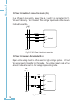
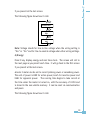
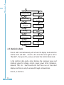
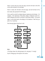
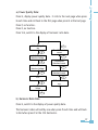
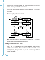
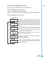
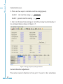
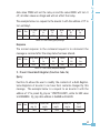
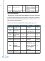
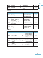
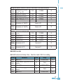
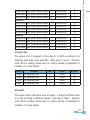
1
© Copyright 2007 V1.2 This manual may not be reproduced in whole or in part by any means, without the expressed written consent of Accuenergy. The information contained in this document is believed to be accurate at the time of publication, however, Accuenergy assumes no responsibility for any errors which may appear here and reserves the right to make changes without notice. Please ask the local representative for latest product specifications before ordering. I Please read this manual carefully before doing installation, operation and maintenance of Acuvim II meter. Following symbols are used in this user’s manual and on Acuvim II meter to alert the dangerous or to prompt in the operating or set process. Dangerous symbol, Failure to observe the information may result in injury or death. Alert symbol, Alert the potential dangerous. Observe the information after the symbol to avoid possible injury or death. This mark is on product for UL Listed product Installation and maintenance of the Acuvim II meter should only be performed by qualified, competent personnel that have appropriate training and experience with high voltage and current device. This document is not fit for people without adequate experience and training. Accuenergy is not liable for any problems occurring under proper operation. II Content Chapter 1 Introduction-------------------------------------------------------------------1 1.1 The Purpose of Acuvim II--------------------------------------------------2 1.2 The Application Area of Acuvim II---------------------------------------3 1.3 The Function of Acuvim II-------------------------------------------------3 Chapter 2 Installation-------------------------------------------------------------------5 2.1 Appearance and Dimensions--------------------------------------------8 2.2 Installation Method------------------------------------------------------9 2.3 Wiring of Acuvim II-------------------------------------------------------11 Chapter 3 Meter Operation and Parameter Setting---------------------------------27 3.1 Display Panel and Keys---------------------------------------------------28 3.2 Metering Data-------------------------------------------------------------31 3.3 Statistics Data-------------------------------------------------------------34 3.4 Demand Data--------------------------------------------------------------36 3.5 Harmonic Data------------------------------------------------------------36 3.6 Expanded I/O Module Data----------------------------------------------38 3.7 Parameter Setting Mode-------------------------------------------------42 3.8 Page recovery Function--------------------------------------------------56 Chapter 4 Function and Software-----------------------------------------------------57 4.1 Basic Analog Measurements---------------------------------------------58 4.2 Max/Min--------------------------------------------------------------------61 4.3 Harmonics and Power Quality Analysis--------------------------------62 4.4 Over-Range Alarming-----------------------------------------------------63 4.5 Extended I/O Module----------------------------------------------------72 4.6 Extended Communication Block---------------------------------------72 Chapter 5 Function and Software-----------------------------------------------------73 III 5.1 Introducing Modbus Protocol--------------------------------------------74 5.2 Format of Communication----------------------------------------------77 5.3 Data Address Table and Application Details of Acuvim II-----------82 Appendix--------------------------------------------------------------------------------107 Appendix A Technical data and specifications--------------------------------------108 Appendix B Ordering Information----------------------------------------------------111 Appendix C Revision History----------------------------------------------------------112 IV Starting! Congratulations! You have received an advanced, versatile, multifunction power meter, also known as a Remote terminal unit (RTU), which will greatly benefit your power system. When you open the package, you will find the following items 1. 2. 3. 4. 5. Acuvim II meter Pluggable Terminal Installation clips User’s operation manual Maintenance guarantee card 1 3 4 1 1 Please read this manual carefully before operating or setting the Acuvim II meter to avoid unnecessary trouble. You can read part of this manual depends on how you use the Acuvim II meter. Chapter 1 helps you to understand the fundamental function, specification and application area of Acuvim II. Chapter 2 describes detailed installation and wiring of Acuvim II. Chapter 3 describes the data display and parameter setting method. Chapter 4 outlines the functions of Acuvim II and the way to use them. Chapter 5 gives the address table of Acuvim II. Appendix lists the technical data and specifications and ordering information. V VI Chapter 1 Introduction The Purpose of Acuvim II The Application Area of Acuvim II The Functions of Acuvim II 1 1.1 The Purpose of Acuvim II Powerful Multifunction Power Meter Acuvim II Multifunction digital power meter is designed using modern MCU and DSP technology. It integrates three-phase energy measuring and displaying, energy accumulating, power quality analysis, malfunction alarming and network communication. Large and vivid LCD meets your visual requirement greatly. Graceful and high-lighted back light makes it easy to check the measuring data. Simple HMI interface makes it easy to master. Multi-row displaying lets you observe various data without touching any keys. Ideal Choice for Electric Automation SCADA System Acuvim II can be used to replace all traditional electric meters. It also can be used as Remote Terminal Unit (RTU) for monitoring and controlling in a SCADA system. All the measured data is available via digital RS485 communication ports running the ModbusTM protocol. Energy Management Acuvim II can measure bidirectional four quadrants kWh and kvarh. It can provide maximum/minimum energy data and energy demand data. With the help of master software, you can easily know how the load and energy are running. It automatically gives you all kinds of measurement tables as well. Remote Power Control The main function of Acuvim II is measuring, and it also has some flexible I/O functions, which make the meter very useable as a distributed RTU (metering, monitoring, remote controlling in one unit). Power Quality Analysis With the help of powerful digital signal processing technology, the Acuvim II intelligent power meter can be used as an online power quality analysis instrument. It can simultaneously and continuously give out the analysis results such as THD of voltage and current, harmonics up to 31st order and unbalance factor of voltage and current, etc. 1.2 The Application Area of Acuvim II Power Distribution Automation Intelligent Electric Switch Gear Industry Automation Building Automation Energy Management System Substation Automation Resident district power monitoring 1.3 The Function of Acuvim II Multifunction, High Accuracy Acuvim II Multifunction Intelligent power meter is powerful in data collecting and processing. It can not only measure up to several decades of power parameters, but also do demand metering, harmonic analysis, statistics of max/min, over range alarming, energy accumulating etc. Accuracy of Voltage and Current is 0.2%, True-RMS. Accuracy of Power and Energy is 0.5%, four quadrants metering. Small Size and Easy Installation Acuvim II can be installed using a standard ANSI C39.1 (4” Round) or an IEC 92mm DIN (Square) form. With the 51mm depth after mounting, the Acuvim II can be installed in a small cabin. The fixing clips are used for easy installation and remove. Easy to Use With a large high density LCD screen, the display of the Acuvim II is easy to read and use. All the measuring data and setting parameters can be accessed by using panel keys or a communication port. The setting parameters are protected in EEPROM, which will maintain its content after the meter is powered off. With the backlight of the LCD, the display can be easily read in a dim environment. The back light “on” time is selectable. Multiple Wiring Modes The Acuvim II can easily be used in high voltage, low voltage, three phase three wires, three phase four wires and single phase system using approximate wiring. High safety, high stability Acuvim II was designed according to industrial standards. It can run stably under high power disturbance condition as it has passed EMC and Safety test according to IEC standards and UL certification. Chapter 2 Installation Appearance and Dimensions Installation Method Wiring of Acuvim II 5 Considerations When Installing Meters Installation of the Meter must be performed by only qualified personnel who follow standard safety precautions during all procedures. Those personnel should have appropriate training and experience with high voltage devices. Appropriate safety gloves, safety glasses and protective clothing are recommended. During normal operation of the Meter, dangerous voltages flow through many parts of the meter, including: Terminals and any connected CTs (Current Transformers) and PTs (Potential Transformers), all I/O Modules (Inputs and Outputs) and their circuits. All Primary and Secondary circuits can, at times, produce lethal voltages and currents. Avoid contact with any current-carrying surfaces. Do not use the meter or any I/O Output Device for primary protection or in an energy-limiting capacity. The meter can only be used as secondary protection. Do not use the meter for applications where failure of the meter may cause harm or death. Do not use the meter for any application where there may be a risk of fire. All meter terminals should be inaccessible after installation. Do not apply more than the maximum voltage the meter or any attached device can withstand. Refer to meter and/or device labels and to the Specifications for all devices before applying voltages. Do not HIPOT/ Dielectric test any Outputs, Inputs or Communications terminals. ACCUENERGY recommends the use of Shorting Blocks and Fuses for voltage leads and power supply to prevent hazardous voltage conditions or damage to CTs, if the meter needs to be removed from service. CT grounding is optional. ACCUENERGY recommends use dry cloth to wipe the meter. NOTE: IF THE EQUIPMENT IS USED IN A MANNER NOT SPECIFIED BY THE MANUFACTURER, THE PROTECTION PROVIDED BY THE EQUIPMENT MAY BE IMPAIRED. NOTE: THERE IS NO REQUIRED PREVENTIVE MAINTENANCE OR INSPECTION NECESSARY FOR SAFETY. HOWEVER, ANY REPAIR OR MAINTENANCE SHOULD BE PERFORMED BY THE FACTORY. DISCONNECT DEVICE: The following part is considered the equipment disconnect device. A SWITCH OR CIRCUIT-BREAKER SHALL BE INCLUDED IN THE ENDUSE EQUIPMENT OR BUILDING INSTALLATION. THE SWITCH SHALL BE IN CLOSE PROXIMITY TO THE EQUIPMENT AND WITHIN EASY REACH OF THE OPERATOR. THE SWITCH SHALL BE MARKED AS THE DISCONNECTING DEVICE FOR THE EQUIPMENT. The installation method is introduced in this chapter. Please read this chapter carefully before beginning installation work. 2.1 Appearance and Dimensions Appearance ⑤ ① ② ③ ⑦ ⑧ ④ ⑨ ⑥ Fig 2.1 Appearance of Acuvim II Part Name 2. Front Casing 3. LCD Display Description The Acuvim II enclosures are made of high strength anti-combustible engineering plastic After the installation, this part is before the panel. Large bright white backlight LCD Display 4. Key Four keys are used to select display and set 5. Voltage Input Terminals 6. Current input Terminals 7. Power Supply Terminals 8. Communication Terminals 9. Installation Clip Used for Voltage input Used for Current input Used for Supply input 1. Enclosure Communication output The clips are used for fixing the meter to the panel Table 2.1 Part name of Acuvim II Dimensions (mm) Front view Side view Fig 2.2 Dimensions 2.2 Installation Method Environmental Before installation, please check the environment temperature and humidity to ensure the Acuvim II meter is being placed where optimum performance will occur. Temperature Operation: -25℃ to 70℃. Storage: -40℃ to 85℃ Humidity 5% to 95% non-condensing. Acuvim II meter should be installed in dry and dust free environment and avoid heat, radiation and high electrical noise source. Installation Steps Acuvim II can be installed using a standard ANSI C39.1 (4” Round) or an IEC 92mm DIN (Square) form. 1. Firstly, cut a square hole or round hole on the panel of the switch gear. The cutting size is shown in fig 2.3. The Unit is mm. Fig 2.3 Panel Cutting 2. Secondly, remove the clips from the meter, and insert the meter into the square hole from the front side. 10 Fig 2.4 Put the meter into the square hole 3. Finally, put clips back to the meter from the backside and push the clip tightly so that the meter is fixed on the panel. Fig 2.5 Use the clips to fix the meter on the panel 2.3 Wiring of Acuvim II Terminal Strips There are four terminal strips on the back of Acuvim II. The 1, 2 and 3 are used to represent each phase of three phase system. They have the same meaning with A, B and C or R, S and T in three phase system. 11 Current Input Terminal Strip ! I 11 1 I 1 I 1 I I1 5 Voltage Input Terminal Strip V1 V V 10 VN Power Supply Terminal strip 11 1 1 L/ + N/ – Power Supply Communication terminal strip Comm Port A B S 1 15 1 Fig 2-6. Terminal Strips of Acuvim II 12 I DANEROUS Only the qualified personnel could do the wire connection work. Make sure the power supply is cut off and all the wires are powerless. Failure to observe it may result in severe injury or death. Safety Earth Connection Before doing the meter wiring connection, please make sure that the switch gear has a safety Earth system. Connect the meter safety earth terminal to the switch gear safety earth system. The following safety earth symbol is used in this user’ s manual. Fig 2-7 Safeth Earth Symbol NOTE Make sure the auxiliary power terminal of the meter ground is connected to the safety Earth of switchgear. NOTE Make sure the voltage of power supply is the same as what the meter needed for its auxiliary power. Auxiliary Power The auxiliary power supply of the Acuvim II meter is 100-415Vac (50/60Hz) or 100-300Vdc. The meter’s typical power consumption is very little so it can be supplied by an independent source or by the line to be measured. A regulator or a UPS should be used when the power supply undulates too much. The terminals for the auxiliary power supply are 11, 12 and 13 (L, N, and Ground). A switch or circuit-breaker shall be included in the building installation, and it shall be in close proximity to the equipment and within easy reach of the operator, and it shall be marked as the disconnecting device for the equipment. 13 1A FUSE Power Supply 11 L 1 N Acuvim II 1 Ground Fig 2-8 Power supply A fuse (typical 1A/250Vac) should be used in auxiliary power supply loop. No. 13 terminal must be connected to the safety earth system of switchgear. An isolated transformer or EMC filter should be used in the auxiliary power supply loop if there is power quality problem in the power supply. NOTE A filter should be used if there is EMI problem. 1A FUSE Power Supply Ground L L 11 L N N 1 N G G 1 Acuvim II EMC Filter Fig 2-9 Power supply under noisy condition Choice of wire of power supply could be AWG22-16 or 0.6-1.5mm2. Voltage Input Input voltage of Acuvim II should be 400 LN/690 LL VAC rms(three phases),400 LN VAC(single phase). In high voltage system, a PT must be used. The secondary output of the PT should be 100V or 120V typically. The accuracy of measurement is related to the PT you select, so be careful! For the star system, the 14 primary rated voltage of PT is equal to or close to the phase voltage of the system. For the delta system, it is the line voltage of the system. A fuse (typical 1A/250Vac) should be used in voltage input loop. The wire of voltage input could be AWG16-12 or 1.3-2.0mm2. Note: In no circumstance could the secondary of PT be shorted. The secondary of PT should be well grounded at one end. Current Input In a practical engineering application, CTs should be installed in the loop of measuring. Normally the secondary of CT is 5A. 1A is possible in the ordering option. A CT of accuracy over 0.5% (rating over 3VA) is recommended and it will influence the measuring accuracy. The wire between CT and Acuvim II should be as short as possible. The length of the wire may increase the error of the measurement. CTs must be required if the rated current is over 5A. The wire number of current input could be AWG15-10 or 1.5-2.5mm2. The CT loop should not be open circuit in any circumstance when the power is on. There should not be any fuse or switch in the CT loop and one end of the CT loop should be well connected to the ground. Vn Connection Vn is the reference point of Acuvim II voltage input. The lower is the wire resistance the better is the accuracy. The wiring mode of Vn depends greatly on the system wiring mode. Please refer to the wiring diagram. Three phase wiring diagram Acuvim II can satisfy almost all kinds of three phase wiring diagram. 15 Please read this part carefully before you begin to do the wiring so that you can choose a suitable wiring method for your power system. The voltage and current input wiring mode can be set separately in the meter parameter setting process. The voltage wiring mode could be 3-phase 4-line Wye (3LN), 3-phase 4-line 2PT Wye mode (2LN) and 3-phase 3-line open delta (2LL). The current input wiring mode could be 3CT, 2CT and 1CT. Any voltage mode could be group with one of the current mode. Voltage Input Wiring 3-Phase 4-Line Wye mode (3LN) The 3-Phase 4-Line Wye mode is popularly used in low voltage electric distribution power system. The power line can be connected to the meter voltage input directly as in fig 2.10a. In the high voltage input system, 3PT Wye mode is often used as in fig 2.10b. The voltage input mode of the Acuvim II should be set 3LN for both voltage input wiring mode. LINE A B C N 1A FUSE V1 V V 10 VN Acuvim II LOAD Fig 2.10a 3LN direct connection 16 LINE A B C N 1A FUSE V1 V V 10 VN Acuvim II LOAD Fig 2.10b 3LN with 3PT 3-Phase 4-Line 2PT mode (2LN) In some 3-Phase 4-Line Wye system, 2PT Wye mode is often used as in fig2.11, where the 3 phases of power system is supposed to be balanced. The voltage of V2 is calculated according to the V1 and V3. The voltage input mode of the Acuvim II should be set 2LN for 2PT voltage input wiring mode. LINE A B C N 1A FUSE V1 V V 10 VN Acuvim II LOAD Fig 2.11 2LN with 2PTs 17 3-Phase 3-Line direct connection mode (3LL) In a 3-Phase 3-Line system, power line A, B and C are connected to V1, V2 and V3 directly. Vn is floated. The voltage input mode of the Acuvim II should be set 3LL. LINE A B C 1A FUSE V1 V V 10 VN Acuvim II LOAD Fig 2.12 3LN 3-Phase 3-Line direct connection 3-Phase 3-Line open Delta Mode (2LL) Open delta wiring mode is often used in high voltage system. V2 and Vn are connected together in this mode. The voltage input mode of the Acuvim II should be set 2LL for voltage input wiring mode. LINE A B C 1A FUSE V1 V V 10 Vn LOAD Fig 2.13 2LL with 2PTs 18 Acuvim II Current Input Wiring 3CT All the current input of three phase system can be looked as 3CT one, whether there are 2 CTs or 3 CTs in the input side. The current input mode of the Acuvim II should be set 3CT for this current input wiring mode. LINE A B C Terminal block 5 1 I11 I1 I1 I 5 I1 I Acuvim II LOAD Fig 2.14 3CTs a LINE A B C Terminal block 5 1 I11 I1 I1 I 5 I1 I Acuvim II LOAD Fig 2.15 3CTs b 19 2CT The difference of the fig 2.16 and the fig.2.15 is that there is no current input in the I21 and I22 terminals. The I2 value is calculated from formula i1+i2+i3=0. The current input mode of the Acuvim II should be set 2CT for this current input wiring mode. LINE A B C Terminal block 5 1 I11 I1 I1 I 5 I1 I Acuvim II LOAD Fig 2.16 2CTs 1CT If it is a three phase balance system, 1 CT connection method can be used. All the other two current are calculated according to the balance supposing. LINE A B C Terminal block LOAD Fig 2.17 1CT 20 5 1 I11 I1 I1 I 5 I1 I Acuvim II Frequently used wiring method The voltage and current wiring method are put together in one drawing. The Acuvim II meter will display normally only that the setting of the meter is assorted with the wiring of the voltage and current input. 1. 3LN, 3CT with 3 CTs LINE A B C N 1A FUSE Terminal block 5 1 I11 I1 I1 I 5 I1 I 10 VN V V V1 Acuvim II LOAD Fig 2.18 3LN, 3CT 2. 3LN, 3CT with 2 CTs LINE A B C N 1A FUSE Terminal block 5 1 I11 I1 I1 I 5 I1 I 10 VN V V V1 Acuvim II LOAD Fig 2.19 3LN, 3CT with 2CTs 21 3. 2LN, 2CT LINE A B C N 1A FUSE Terminal block 5 1 I11 I1 I1 I 5 I1 I 10 VN V V V1 Acuvim II LOAD Fig 2.20 2LN, 2CT 4. 2LN, 1CT LINE A B C N 1A FUSE Terminal block 5 1 I11 I1 I1 I 5 I1 I LOAD Fig 2.21 2LN, 1CT 22 10 VN V V V1 Acuvim II 5. 2LL, 3CT LINE A B C 1A FUSE Terminal block 5 1 I11 I1 I1 I 5 I1 I 10 VN V V V1 Acuvim II LOAD Fig 2.22 2LL, 3CT 6. 2LL, 2CT LINE A B C 1A FUSE Terminal block 5 1 I11 I1 I1 I 5 I1 I 10 VN V V V1 Acuvim II LOAD Fig 2.23 2LL, 2CT 23 7. 2LL, 1CT LINE A B C 1A FUSE Terminal block 5 1 I11 I1 I1 I 5 I1 I 10 VN V V V1 Acuvim II LOAD Fig 2.24 2LL, 1CT 8. Single Phase 2 Line (Wiring mode setting 3LN, 3CT) LINE A N 1A FUSE Terminal block 5 1 I11 I1 I1 I 5 I1 I 10 VN V V V1 Acuvim II LOAD Fig 2.25 Single phase 2Lines 24 9. Single Phase 3 Line (Wiring mode setting 3LN, 3CT) LINE A N B 1A FUSE Terminal block 5 1 I11 I1 I1 I 5 I1 I 10 VN V V V1 Acuvim II LOAD Fig 2.26 Single phase 3Lines Communication The communication port and protocol of Acuvim II are RS485 and ModbusRTU. The terminals of communication are A, B, and S (14, 15, 16). A is differential signal +, B is differential signal - and S is connected to shield of twisted pair cable. Please use good quality shielded twisted pair cable, AWG22 (0.5mm2) or higher. The overall length of the RS485 cable connecting all devices should not exceed 1200m (4000ft). Acuvim II is used as a slave device of masters like PC, PLC, data collector or RTU. If the master does not have RS485 communication port, a converter has to be used. Normally a RS232/RS485 or USB/RS485 is adopted. The topology of RS485 net can be line, circle and star. For the high quality communication, good quality shielded twisted pair of cable AWG22 (0.5mm2) or higher is very important. 25 The shield of each segment of the RS485 cable must be connected to the ground at one end only. Every A(+) should be connected to A(+), B(-) to B(-), or it will influence the network, or even damage the communication interface. The connection topology should avoid “T” type which means there is a new branch and it does not begin from the beginning point. Keep communication cables away as much as possible from sources of electrical noise. When many devices are connected to the same long communication line, an antireflection resistor of 120Ω-300Ω is preferred which will be connected to A and B at the end of the line. Use RS232/RS485 or USB/RS485 converter with optical isolated output and surge protection. 26 Chapter 3 Meter Operation and Parameter Setting Display Panel and Keys Metering Data Statistics Data Demand Data Harmonic Data Expanded I/O Module Data Parameters Setting 27 Detailed human-machine interface of the meter will be described in this chapter, including how to get the metering data and how to do the parameter setting. 3.1 Display Panel and Keys There are one display panel and four keys in the front of Acuvim II. All the display segments are illustrated in fig 3.1. Users should note that all the segments will not display in a single page when normally used. 1 10 4 5 2 6 7 8 9 3 11 12 17 13 14 15 16 Fig3.1 All Display Segments 28 SN Display 1 Display mode indication Description It shows the topic of the display area, “Meter” for real-time measurement; “Max/Min” for statistic data; “Demand” for power demand data; “Harmonic” for harmonic data; “Setting” for parameters setting; “Digital I/O” for expended IO module data. 2 3 4 5 6 Main Display Area: display metering data such as voltage, current, power, power Four lines of “ ” letters in factor, frequency, imbalance, phase angle, etc; display statistics such as maximum and the metering area minimum; display demand data; display settings and display expanded I/O data. Display energy data and real-time clock. Also four “ ” and five “ ” used for the setting mode and digital I/O letters mode display. Item label: “U” for voltage; “I” for current; “P” for active power; “Q” for reactive power; “S” for apparent power; “PF” for power factor; “F” for frequency; “∠” for phase three “ ” letters angles; “DMD” for demand; display setting page number; display expanded IO module type for “Mxx”. Item Label: “Unbalance” for imbalance of the voltage and current; “THD” for total Unbalance、THD、TDD、 harmonics distortion; “TDD” for total demand MAX、MIN distortion; “MAX” for maximum and “MIN” for minimum Display the percentage of the load current to Load rate the nominal current. Four quadrant label 7 and load type label 8 9 : the quadrant of the system power Inductor label: inductive load Capacitor label: capacitive load 1, 2, 3 for 3 phase A, B, C; 1-2, 2-3, 3-1 for 3 phase line-to-line AB, BC, CA; avg for average and N for neutral. Imp: consumption energy; Energy label: Imp, Total, Net, Exp: generation energy; Exp Total: absolute sum of Imp and Exp energy Net: algebraic sum of Imp and Exp energy 1-2, 2-3, 3-1, avg, N 29 voltage: V,kV; current: A,kA;active power: kW, MW; reactive power: kvar, Mvar; apparent power: kVA, MVA; frequency: Hz; active energy: kWh; reactive energy: kVarh; apparent energy: kVAh; percentage: %; phase angle: ° No label: no communication One label: inquiry Two labels: inquiry and answer 10 Unit 11 Communication label 12 Energy pulse output indicator No label: no pulse output With label: pulse output 13 14 15 Expanded I/O module indicator Profibus module indicator None: Profibus module not connected illume: Profibus module connected Ethernet module indicator None: Ethernet module not connected illume: Ethernet module connected 16 17 M1: one AXM-IO1 connected M1x2: two AXM-IO1 connected None: no AXM-IO1 connected M2: one AXM-IO2 connected M2x2: two AXM-IO2 connected None: no AXM-IO2 connected M3: one AXM-IO3 connected M3x2: two AXM-IO3 connected None: no AXM-IO3 connected reserved time label Time display in energy area There are four keys in the front panel, label as H, P, E and V/A from left to right. Use these four keys to read metering data and set the parameters. Note: If the backlight is off before you press any keys, it will become on and no other functions will be activated. 30 3.2 Metering Data Press H and V/A simultaneously will activate the display mode selection and the cursor will flash. Press P or E to move the cursor right or left to “Meter”, then press V/A, and you will enter the metering mode. In the metering mode, meter displays measurements such as voltage, current, power, power factor, phase angle, imbalance, etc. a) Voltage and Current: Press V/A to read voltage and current in the metering area. The screen will roll to the next page as you press V/A each time. It will go back to the first screen if you press V/A at the last screen. The following figure shows how it rolls: V/A Three phase Voltage & avg V/A Three phase Current & In V/A Line Voltage & avg V/A Three phase Current & avg V/A Note: When the meter is set to “2LL” or “3LL”, there is no phase voltage and neutral current display. So only the third and fourth screens will be displayed. 31 b) Power, Power Factor and Frequency: Press P, display power related data. The screen will roll to the next page as you press P each time. It will go back to the first screen if you press P at the last screen. The following figure shows how it rolls: P Three phase power P Three phase reactive power P Three phase apparent power P Three phase PF P System power P System power factor & frequency P Note: When the meter is set to “2LL” or “3LL”, only the fifth and sixth screens will be displayed. c) Phase Angles and Imbalance: Press H, display phase angles and imbalance data. The screen will roll to the next page as you press H each time. It will go back to the first screen 32 if you press H at the last screen. The following figure shows how it rolls: H Unbalance factor H Voltage phase angle H Current phase angle H Note: Voltage stands for line-to-line voltage when the wiring setting is “2LL” or “3LL” and for line-to-neutral voltage when other wiring settings. d) Energy: Press E key, display energy and real time clock. The screen will roll to the next page as you press E each time. It will go back to the first screen if you press E at the last screen. Acuvim II meter can be set to record primary power or secondary power. The unit of power is kWh for active power, kvarh for reactive power and kVAh for apparent power. The running time begins to take record at the time when the meter is turned on, with the accuracy of 0.01H and is stored in the non-volatile memory. It can be reset via communication and panel. The following figure shows how it rolls: 33 E Consumption energy E Generation energy E Total energy E Net energy E The absorption reactive energy E The generation reactive energy E Meter running time E Time Format: hh:mm:ss E Date Format: mm:dd:yyyy E Total electrical degree E Net reactive energy E Total reactive energy E 3.3 Statistics Data Press H and V/A simultaneously will activate the display mode selection and the cursor will flash. Press P or E to move the cursor right or left to “Max/Min”, then press V/A, and you will enter the statistics data mode. In the statistics data mode, meter displays the maximum values and minimum values for voltage, current, power, power factor, imbalance, demand, THD, etc. User should note that there are no time label displays and they can only be accessed through communication. Press H, no functions. 34 Press P, screen will roll to the next page, and will roll back to the first screen when pressed at the last page. Press E, screen will roll back to the last page, and will roll back to the last screen when pressed at the first page. V/A is used for switch the display between maximum and minimum. For example, if the maximum of the phase voltage is displayed, press V/A, and the display will switch to minimum of the phase voltage. If you press again, it will switch back to the display of the maximum. Each time you press V/A, it switches. The following figure shows how it rolls: P Max value of phase voltage Max value of current harmonics P Max value of the line to line voltage P Max value of voltage harmonics P Max value of current P Max value of power P Max value of the demand P Max value of unbalance factor P P Max value of power factor & frequency Note: i) The figure shows the rolling sequence for using key P. If using E key for rolling page, the sequence will reverse. 35 ii) When meter is set to “2LL” or “3LL”, the first screen will not be displayed. 3.4 Demand Data Press H and V/A simultaneously will activate the display mode selection and the cursor will flash. Press P or E to move the cursor right or left to “Demand”, then press V/A, and you will enter the demand data mode. In the demand data mode, there is only one page, displaying the demand of active power, reactive power and apparent power. As shown in the figure, system active power demand is 3.285kW, system reactive power demand is 0 kvar, system apparent power demand is 3.285 kVA. 3.5 Harmonic Data Press H and V/A simultaneously will activate the display mode selection and the cursor will flash. Press P or E to move the cursor right or left to “Harmonic”, then press V/A, and you will enter the harmonic data mode. In the harmonic data mode, meter displays the harmonic ratio of voltage and current, THD, odd HD, even HD, THFF, CF and KF. 36 a) Power Quality Data: Press H, display power quality data. It rolls to the next page when press H each time and roll back to the first page when press H at the last page. Press P, no function. Press E, no function. Press V/A, switch to the display of harmonic ratio data. THD of voltage & avg H Odd harmonic distortion of voltage H Even harmonic distortion of voltage H The “K”factor of current H Even harmonic distortion of current H H Odd harmonic distortion of current H THD of current & avg H THFF Crest factor of Voltage H b) Harmonic Ratio Data Press H, switch to the display of power quality data. The harmonic order will add by one when press P each time and will back to 2nd when press P at the 31st harmonics. 37 The harmonic order will minus by one when press E each time and will back to 31 when press E at the 2nd harmonics. Press V/A, switch display between voltage harmonics and current harmonics. The following figure shows how it rolls: V/A The nd harmonic ratio of voltage V/A The nd harmonic ratio of current V/A The rd harmonic ratio of current V/A The th harmonic ratio of current V/A 1st harmonic ratio ofcurrent P P The rd harmonic ratio of voltage P P The th harmonic ratio of voltage P P 1st harmonic ratio of voltage P P Note: The figure shows the rolling sequence for using key P. If using E key for rolling page, the sequence will reverse. 3.6 Expanded I/O Module Data Press H and V/A simultaneously will activate the display mode selection and the cursor will flash. Press P or E to move the cursor right or left to “Digital I/O”, then press V/A, and you will enter the expanded I/O module data mode. 38 In the expanded I/O module data mode, meter displays the data from expanded I/O modules, such as DI status, pulse counter number, Relay status, Analog Output, and Analog Input, etc. In the expanded I/O module data mode, first page is the module selection and you can choose any module as you wish. If no expanded I/O module is connected, it will display “NO IO”. a) Module Selection: Press H, no function. Press P, move the cursor downwards. When the cursor is at the bottom, press P will move the cursor to the top. If there is only one module connected, press P will have no effect. Press E, move the cursor upwards. When the cursor is at the top, press E will move the cursor to the bottom. If there is only one module connected, press E will have no effect. Press V/A, select the module and enter the I/O module data selection mode. 39 As shown in the figure, three modules are connected, AXM-IO11, AXMIO21, AXM-IO31, which are indicated by M11, M21, M31 respectively. The cursor points to M21, which indicates that AXM-IO21 is chosen now. b) I/O Module Data Selection Press H, back to module selection mode. Press P, move the cursor downwards. When the cursor is at the bottom, press P will move the cursor to the top. Please note that there are 3 parameters for AXM-IO1, 3 parameters for AXM-IO2 and 4 parameters for AXM-IO3. Press E, move the cursor upwards. When the cursor is at the top, press E will move the cursor to the bottom. Press V/A, select the parameter and enter the display of the data. c) I/O module data display Press H, back to I/O module data selection mode. The screen will roll to the next page each time when press P and will roll back to the first page when press P at the last page. If only one page exist, press P will have no effect. The screen will roll to the last page each time when press E and will roll back to the last page when press E at the first page. If only one page exist, press E will have no effect. Press V/A, no function. The following figure shows how it rolls: 40 V/A M11(M1): DI1- H P P M11(M1): DI- M11(M1): DI M11/M1 V/A IO: M11 or M1 H V/A M11(M1): RO M11(M1): pluse count H M11(M1): RO1、RO V/A M11(M1): Counter 1 H P M11(M1): Counter P M11(M1): Counter P M11(M1): Counter P M11(M1): Counter 5 P M11(M1): Counter P V/A M1(M): DI M1/M M1(M): DI1- H V/A IO: M21 or M H V/A M1(M): AO M1(M): pulse count H M1(M): AO1、AO2 output V/A M1(M):Counter 1 H P M1(M):Counter P M1(M):Counter P M1(M):Counter P 41 V/A M1(M):DI Module: M1/M M1(M): DI1- H V/A IO: M31 or M H V/A M1(M):RO M1(M): pulse count H M1(M): RO1、RO V/A M1(M): Counter1 H P M1(M): Counter P M1(M): Counter P M1(M): Counter P V/A M1(M):AI M1(M):AI1、AI2 input H Note: The figure shows the rolling sequence for using key P. If using E key for rolling page, the sequence will reverse. 3.7 Parameter Setting Mode Press H and V/A simultaneously will activate the display mode selection and the cursor will flash. Press P or E to move the cursor right or left to “Setting”, then press V/A key and you will enter the parameter setting mode. In the parameter setting mode, parameters, such as system parameters, expanded I/O module parameters, alarm parameters and Ethernet module parameters, can be read and modified. a) Password Inquiry: 42 Entering the parameter setting mode, firstly, the device address will appear for several seconds and then go to the password inquiry page. “Password” is the key to the parameter setting mode and only valid password will help you to go through and use the meter setting. This function helps to prevent the mis-operation and unauthorized people to modify the meter parameters. There are 4 digits of password in the meter, which can be set from “0000” to “9999” with the default value of “0000”. User should input the right password and press V/A key to go through to the parameter selection page; otherwise it will stay at the password inquiry page. The following figure shows the password inquiry page. Key functions when inputting password: Press Press Press Press H, move the flashing cursor to the next position. P, the flashing number will add one. E, the flashing number will minus one. V/A, confirm the password. b) Parameter Selection Mode In the parameter selection mode, there are four parameters for choices: system, expanded I/O module, Ethernet module and alarms. 43 Press H, no function. Press P, move the cursor downwards. When the cursor is at the bottom, press P will move the cursor to the top. Press E, move the cursor upwards. When the cursor is at the top, press E will move the cursor to the bottom. Press V/A, choose the parameter and enter the parameter modify mode. The figure shows the parameter selection page. “SYS” stands for system parameter, “I/O” stands for expanded I/O module parameter, “NET” stands for Ethernet module parameter and “ALM” stands for alarm parameter. As shown in the figure, the cursor points to the “SYS”, which means system parameter is selected. c) System Parameter Setting In the system parameter setting mode, firstly find the parameter and then modify. Key functions for finding the parameter: Press H, back to parameter selection mode. 44 The screen will roll to the next page each time when press P and will roll back to the first page when press P at the last page. The screen will roll to the last page each time when press E and will roll back to the last page when press E at the first page. Press V/A, confirm the parameter you want to modify, enter the modify mode. Key functions for modifying the parameter: Press Press Press Press H, move the flashing cursor to the next position. P, the flashing number will add one. E, the flashing number will minus one. V/A, confirm the modification and back to parameter finding mode. The following figure shows how it rolls: 45 SYS setting V/A S01: Meter address Any integer from 1~ P S0: Baud rate Select form 00,100, 00,00,00,100,38400 bps P S0: Voltage wiring Voltage wiring mode can be one of “ LN”, “LN”, “LL”, “LL” P S0: Current wiring Current wiring mode can be one of “ CT” , “1CT” , “CT” P S05: PT1 PT1: primary nominal value of PT, range from 50.0V~500,000.0V S0: PT PT: secondary nominal value of PT, range from 50.0V~00.0V If no PT used , set PT1 and PT2 as the nominal voltage of the meter . S0: CT1 CT1: primary value of CT, range from 1A~50000A; S0: CT CT: secondary value of CT, choose from 1A or 5A; P P P P S0: pulse constant for active energy Indicates the kWh for one pulse . Range from 1~6000 and the unit is 0.1kWh/pulse P S10: pulse constant for reactive energy Indicates the kvarh for one pulse . Range from 1~6000 and the unit is 0.1kvarh /pulse P The “on” time can be set from 0 to 120 Minute. The backlight will always be “on” if the setting value is 0. If it is other value , it means after that long time it will goes off if no key has been pressed . It will be “on” whenever you press any key if it is “off” .。 S11:backlight time P S1:demand calculation method 1: sliding block, : thermal P S1:demand window Range from 1~30 minutes S1:demand clear Yes:clear; No:not clear P 46 P S15:max/min clear To clear the Max and Min value does not mean write 0 to all the registers, it will copy the metering value to the statistic registers and start a new statistic period . P S1:run hour clear Yes:clear; No:not clear P S1:I1 direction P S1:I2 direction To adjust polarity of current , the three current’s direction can be set as “Negative” which means reversing 180 degrees and “Positive” which means normal . P S1:I3 direction P S0:VAR /PF Convention 0: IEC, 1: IEEE P S1:energy clear Yes:clear; No:not clear P S:energy mode Fund: fundamental; Full: full wave P S:calculation method of reactive power 0: true 1: generalized Q = S 2 − P2 P S:energy type Pre: primary energy; Sec: secondary energy P S5:pulse counter clear P S:SOE enable P S:Profibus address Range from 0-. 0: not clear; 1: AXM-IO11 clear; : AXM-IO21 clear; : AXM-IO31 clear; : AXM-IO12 clear; 5 AXM-IO22 clear; : AXM-IO32 clear; Range from 0-. 0: disable; 1: AXM-IO 11 enable; : AXM-IO21 enable; : AXM-IO31 enable; : AXM-IO12 enable; 5 AXM-IO22 enable; : AXM-IO32 enable; Any integer from 0-1 P S:Basic Parameter mode P S:password Pre: primary energy; Sec: secondary energy Last page of the system parameter setting . Set the password in this page and make sure to remember the new password , or you may not use the meter properly . 47 Note: The figure shows the rolling sequence for using key P. If using E key for rolling page, the sequence will reverse. d) Expanded I/O Module Parameter In the expanded I/O module parameter mode, firstly choose the module to be modified and then make the modification. If no expanded I/O module is connected, it will display “NO IO”. At this time, Press H to go back to the parameter selection mode and other keys have no effect. Key functions for I/O module selection: Press H, back to parameter selection mode. Press P, move the cursor downwards. When the cursor is at the bottom, press P will move the cursor to the top. If there is only one module connected, press P will have no effect. Press E, move the cursor upwards. When the cursor is at the top, press E will move the cursor to the bottom. If there is only one module connected, press E will have no effect. Press V/A, select the module and enter the I/O module parameter finding mode. Key functions for finding the I/O module parameter: Press H, back to I/O module selection mode. The screen will roll to the next page each time when press P and will roll back to the first page when press P at the last page. The screen will roll to the last page each time when press E and will roll back to the last page when press E at the first page. Press V/A, confirm the parameter you want to modify, enter the modify mode. 48 Key functions for modifying the parameter: Press Press Press Press H, move the flashing cursor to the next position. P, the flashing number will add one. E, the flashing number will minus one. V/A, confirm the modification and back to parameter finding mode. The following table shows how it rolls: Module M11/M12 I/O:M11/M12 Module V/A M11(M12):pulse counter enable P M11(M12):pulse constant P M11(M12):relay output mode DI of AXM-IO1 can be used as the pulse counter, each DI function is correspond to one bit of a 8-bit register. The correspondence bit of 0 means that the DI works as the digital status input and the correspondence bit of 1 means that the DI works as the pulse counter. For example, if the setting value is 000001, it means that DI1 is set as the pulse counter and other DI works as he digital status input. If the DI works as the pulse counter, then when pulse number counted by DI reach the pulse constant, the pulse counter will add by one, which means that the real pulse number equals the number of pulse counter times the pulse constant. Relays of AXM-IO1 can be used as alarm output or control output. ALM:alarm output; CTRL:control output P M11(M12):realy working pattern P M11(M12):relay output pulse width When set as the control output, the relays have the working pattern of latch mode or pulse mode. LATCH:latch mode; PUL:pulse mode If the relay work pattern is pulse mode, it means that the relay will close for a specified period and then open automatically. The pulse width range is 50~3000 ms. 49 Module M 1/M I/O: M1/M22 Module V/A M1(M): pulse counter enable P M1(M): pulse constant P M1(M): DO output mode P M1(M): DO pulse width P M1(M): DO1 output type DI of AXM-IO2 can be used as the pulse counter, each DI function is correspond to one bit of a 8-bit register. The correspondence bit of 0 means that the DI works as the digital status input and the correspondence bit of 1 means that the DI works as the pulse counter. For example, if the setting value is 0001, it means that DI1 is set as the pulse counter and other DI works as he digital status input. If the DI works as the pulse counter, then when pulse number counted by DI reach the pulse constant, the pulse counter will add by one, which means that the real pulse number equals the number of pulse counter times the pulse constant. DO of AXM-IO1 can be used as alarm output or energy pulse output. ALM: alarm output; PUL: energy pulse output Range from 20-1000 ms Choose the output energy type for DO1. Range from 0-4. 0: no output; 1: import active energy; 2: export active power; 3: import reactive energy; 4: export reactive energy. P M1(M): DO2 output type The same as DO1. if the DO is set as the alarm output, this parameter will have no effect. P M1(M): AO type Range: 0~3. 0: 0-20mA; 1: 4-20mA; 2: 0-5V; 3: 1-5V P M1(M): AO1 transforming parameter Range: 0~29, See Chapter 5 P M1(M): AO2 transforming parameter 50 Range: 0~29, See Chapter 5 Module M1/M I/O:M1/M32 Module V/A M1(M):pulse counter enable P M1(M):pulse constant P M1(M):relay output mode DI of AXM-IO can be used as the pulse counter, each DI function is correspond to one bit of a -bit register. The correspondence bit of 0 means that the DI works as the digital status input and the correspondence bit of 1 means that the DI works as the pulse counter. For example, if the setting value is 0001, it means that DI1 is set as the pulse counter and other DI works as he digital status input. If the DI works as the pulse counter, then when pulse number counted by DI reach the pulse constant, the pulse counter will add by one, which means that the real pulse number equals the number of pulse counter times the pulse constant . Relays of AXM-IO can be used as alarm output or control output. ALM:alarm output; CTRL:control output P M1(M):relay working pattern P M1(M):relay output pulse width P M1(M):AI type When set as the control output, the relays have the working pattern of latch mode or pulse mode. LATCH:latch mode; PUL:pulse mode If the relay work pattern is pulse mode, it means that the relay will close for a specified period and then open automatically. The pulse width range is 50~000 ms. Range: 0~. 0:0-0mA; 1:-0mA; :0-5V; :1-5V Note: The figure shows the rolling sequence for using key P. If using E key for rolling page, the sequence will reverse. 51 e) Ethernet Module Parameter In the Ethernet module parameter mode, firstly find the parameter and then modify. If Ethernet module is not connected, all the settings will have no effect. Key functions for finding the Ethernet module parameter: Press H, back to parameter selection mode. The screen will roll to the next page each time when press P and will roll back to the first page when press P at the last page. The screen will roll to the last page each time when press E and will roll back to the last page when press E at the first page. Press V/A, confirm the parameter you want to modify, enter the modify mode. Key functions for modifying the parameter: Press Press Press Press H, move the flashing cursor to the next position. P, the flashing number will add one. E, the flashing number will minus one. V/A, confirm the modification and back to parameter finding mode. The following figure shows how it rolls: 52 Ethernet setting V/A N01: DHCP setting P N0: IP Address P N0: Submask P N04 : Gateway P The selection of DHCP setting : MANU or AUTO Default setting: MANU IP address have four segments . Any segment can be set from 0~55. Default setting: 1.1 .1.5 Submask have four segments. Any segment can be set from 0~55. Default setting: 55.55 .55.0 Gateway have four segments . Any segment can be set from 0~55. Default setting: 1.1 .1.1 N05: DNS1 DNS1 have four segments. Any segment can be set from 0~55. Default setting: 0.10 .0.0 N0: DNS DNS2 have four segments. Any segment can be set from 0~55. Default setting: 0.0.0.0 P P N0: Modbus TCP /IP Port Range from 000 -5 , the default value is 50 N0: Http Port Range from 000 - , the default value is 0 P P N0: Ethernet resetting selection 0: No resetting ; 1: Resetting; : Renew it to default setting, and then resetting it . Note: The figure shows the rolling sequence for using key P. If using E key for rolling page, the sequence will reverse. 53 f) Alarm Parameter In the alarm parameter mode, firstly find the parameter and then modify. Key functions for finding the alarm parameter: Press H, back to parameter selection mode. The screen will roll to the next page each time when press P and will roll back to the first page when press P at the last page. The screen will roll to the last page each time when press E and will roll back to the last page when press E at the first page. Press V/A, confirm the parameter you want to modify, enter the modify mode. Key functions for modifying the parameter: Press Press Press Press H, move the flashing cursor to the next position. P, the flashing number will add one. E, the flashing number will minus one. V/A, confirm the modification and back to parameter finding mode. The following figure shows how it rolls: 54 Alarming setting V/A A01:Alarming enable P A0: Backlight flashing P A0:Alarming records enable P A0: “AND” logic enable P A05: Alarming output to DO1 P Yes: alarming is available; No: means not. It can be selected as cue signal for alarming. Yes: the backlight will flashes; No: means not. There are 16 records in all and each one is corresponding to one bit of a 16-bit register. For each record, it works or not depends on the enable setting. If some bits of the register are "1", it means their corresponding records take effect. While "0" means they don't work. on the panel, it is set as decimal but in the register it is binary, so it needs conversion. There are eight group for "and" logic setting, which can enable the onoff control. One group have two records, when both of the conditional inequality are satisfied, alarming can output. The setting is denoted by Low 8-bit of the 16-bit register, each corresponds for one "and" logic (eight group in all). While "1" means enabled; 0 means not. A0: Alarming output to DO P A0: Alarming output to DO P A0: Alarming output to DO When DO1 works in alarming mode, it is controlled by a 16-bit register which determines which record will output to DO1. On the panel, it is set as decimal but in the register it is binary, so it needs conversion. DO2, DO3 and DO4 are the same as DO1. DO1 and DO2 are the DO of AXM-IO21, DO3 and DO4 are the DO of AXM-IO22. They arrange in order. Note: The figure shows the rolling sequence for using key P. If using E for rolling page, the sequence will reverse. 55 3.8 Page recovery Function Acuvim II has the page recovery function, which means that the meter stores the current display page in the non-volatile memory during power off and reloads the page when power recovers. If power goes off when displaying at the parameter setting mode, the meter will start with page of voltage display when power recovers. If power goes off when displaying at the expanded I/O module data mode, and this expanded I/O module is not connected when power recovers, the meter will start with page of voltage display. 56 Chapter 4 Function and Software Basic Analog Measurements Max/Min Harmonics and power quality analysis Over-Range alarming 57 The function of Acuvim II is very powerful. It can measure almost all the parameters in the power system. Some of its function may not be controlled by simply pressing the keys, so we made this software to go with it. To express clearly, we’ll introduce functions with the help of the software interface in this chapter. The version of the software you get may be advanced or it may differ somewhere, please refer to the manual that goes with it. 4.1 Basic Analog Measurements Acuvim II can measure voltage, current, power, frequency, power factor and demand etc with high accuracy, shown as below: Fig 4.1 Real-Time Metering 58 Demand: Types of demand calculated in Acuvim II are: active power demand of three phase, reactive power demand of three phases, and apparent power demand of three phases. Demand memory can be cleared. To clear is to reset all the registers to 0, like the initial of the meter (demand calculation only). Demand calculating mode can be set as sliding window and thermal according to user. The figure 4-7 shows how it works. In the sliding window interval, you select an interval from 1 to 30 minutes, which is the period of the calculation. The demand updates every 1 minute as the window sliding once. Thermal demand method calculates the demand based on a thermal response which mimics the thermal demand meter. You select the period for the calculation and the demand updates at the end of each period. Energy: Various kinds of energy will be accumulated in Acuvim II. Real time energy: the accumulation of energy for the kWh, kvarh and kVAh since cleared last time. Calculating mode 1. User can select calculating mode from fundamental based or fullwave based by pressing key or via communication. Fundamental based calculating is to accumulate energy ignoring harmonics while full-wave based calculating is to accumulate energy including fundamental and harmonics. Note: When fundamental based calculating is selected, PF is that of 59 fundamental wave. 2. There are two ways to calculate reactive energy(power) Mode 0: real reactive energy Q = S 2 − P 2 − D 2 Mode 1: general reactive energy Q = S 2 − P2 3. User can choose primary energy or secondary energy by pressing key or via communication as shown in figure 4-7. Figure 4-2 energy and power quality parameters Current direction adjustment The normal current direction is from port 1 to port 2, but sometimes 60 we may make wrong wiring. To adjust direction of current, the three current directions can be set as “Negative” which means reversing 180 degrees and “Positive” which means normal. It is easy to get the right data without changing the wiring. It is also shown in figure 4-7. 4.2 Max/Min Figure 4-3 Max/Min Acuvim II can make statistics of the maximum and minimum values of phase/line voltages, currents, power, reactive power, apparent power, power factor, frequency, demand, unbalance factor, THD as well as the time they occur. All the data will be stored in non-volatile memory so 61 that they will not lose when the power supply is off. All of the maximum and minimum data can be accessed via communication or panel, but the time stamps can only be accessed via communication. The statics can be cleared via communication or panel. 4.3 Harmonics and Power Quality Analysis 1. Harmonics Acuvim II can measure and analyze THD, Harmonics (2nd to 31st), even HD, odd HD, Crest Factor, THFF, K factor etc. They are shown in figure 4-2. 2. Phase angle: Phase angle indicates the angle between U1 and other voltage and current parameters. It ranges from 0 to 360 degrees. This function is to help user find out the relationship between all input signals avoiding wrong wiring. When it is set to “2LL” or “3LL”, it gives out the phase angles of u23, i1, i2, i3 corresponding to u12. For other settings, it gives out the phase angles of u2, u3, i1, i2, i3 corresponding to u1. They are shown in figure 4-4. 3. Sequence component and unbalance analysis Acuvim II will do some sequential analysis for the input signal. It makes out the positive sequence, negative sequence and zero sequence of the fundamentals and does the unbalance analysis of voltage and current. Sequence components are shown in figure 4-4, unbalance of voltage and current are shown in figure 4-1. 62 Figure 4-4 Sequence component and Phase angle 4.4 Over-Range Alarming In Acuvim II, when the metering data is over the pre-setting limit and over pre-setting time interval, the over limit alarming will be picked up. The over limit value and time stamp will be recorded and the maximum number of records is 16. The digital output (DO) and RO can be used (if extended I/O modules are connected) as trigger to light or sound alarming. In order to use the over-range alarming function, you should finish all the settings (equation or inequation or enable switches) correctly, or it will fail. All of the settings can be accessed by writing to their corresponding 63 registers via communication as shown in figure 4-5. Figure 4-5 Alarm Setting 1. Single alarming group setting Table 4-1 indicates the first group of settings, there are 16 groups in all with the same format. Address 104eH 104fH 1050H 1051H 1052H Parameter First group: parameter code First group: comparison mode First group: setting value First group: delay time First group: output to relay Range 0~44 1:larger,2:equal,3:smaller Related with parameters 0~3000(*10ms) 0:none,1-8:related relay Table 4-1 first group of alarming settings 64 Property R/W R/W R/W R/W R/W Parameter code: used to select a parameter for this group. For example: 0-frequency, 44-AI4 sampling data. Then this parameter will be monitored. Comparison mode: set alarming condition 1: larger, 2: equal, 3: smaller. For example: if you choose frequency, larger, and setting value is 50, then it will alarm when the frequency is larger than 50Hz. Notice: the relationship between communication setting value and actual value is the same as that of the selected parameter. Delay time: if the alarms condition lasts for a specified time period, an alarm will be valid and recorded. It ranges from 0 to 3000 (unit: 10ms). When it is set to 0, there is no delay after the condition is setup. If it is set to 20, it will delay 20*10=200ms. Output to relay: 0-the alarming will not output to RO, if it is set as 1 and AXM-IO11 is connected, it will output to RO1 when alarm happens and RO1 will be turned off until all alarms output to RO1 are reset. RO2~RO8 are the same as RO1. Notice: if RO is under alarming mode, it can only work in “latch” mode. After single alarming group setting is finished, you need to go on and finish the following global setting or the alarming won’t work. 2. Global settings The addresses of all the global variables are 1046H~104dH in system parameters. “Global alarming enable” determines whether the alarming function of this meter works or not. Only when it is set as “1”, the alarming function is enabled. 65 When “Alarming flash enable“ is set to be “1”, the backlight will flash when alarm happens. “Alarming channel enable setting” determines whether the corresponding group is enabled or not. There are 16 groups in all and each one is corresponding to one bit of a 16-bit register. For each group, whether it works or not depends on the enable setting. If some bits of the register are “1”, it means their corresponding groups take effect. “Logical “And” between alarming setting”: The 16 alarming records in Acuvim II are divided into 8 pairs. Each pair has two groups. The two groups can be logically “and” by controlling the logic switch. When two groups are “and”, the alarming happens only if both the conditions are met. If the switch is off, the two groups work independently. The 8 pairs are arranged as following: according to their serial number, the 1st,2nd make as Pair 1; the 3rd,4th make as Pair 2; the 5th,6th make as Pair 3; 7th,8th make as Pair 4; 9rd,10th make as Pair 5; 11th,12th make as Pair 6; 13th,14th make as Pair 7; 15th,16th make as Pair 8. This function is controlled by the lower 8 bits of 16 bits register, each bit is corresponding to a pair. “1” means this function is enabled and “0” means disabled. “Alarming output to DO1 setting”: When “Digital output mode” is set to “1”, DO1 can be used as alarming output. A 16-bit register is used to finish this function, its bit0~bit15 are corresponding to the 1st ~16th group respectively. When the related I/O module is connected and under alarms mode, if corresponding bit is set to 1 and the alarming condition is met, then it will output to DO1 and DO1 will be turned off until all alarms output to DO1 are reset. If related bit is set to 0, it doesn’t affect DO1. 66 DO2~DO4 are the same as DO1. After finishing the previous steps correctly, the alarming function is available. 3. Setting Example We’ll show you an example of how to use the logical “and” in a pair. We set an event as follow: I1 greater than 180A, delay 5s for the 1st group; U1 less than 9980V, delay 10s for the 2nd group. No output is available. The CT primary value of I1 is 200A, and CT2 is 5A. The primary voltage of U1 is 10000V, PT2 is 100V. Then let’s look how all the related registers are to be set. Settings of first group: “Parameter code (104eH)” is set to 9, which stands for I1. “Comparison mode (104fH)” is set to 1, which stands for larger. “Setting value (1050H)” is set to 4500, according to the relationship between actual value and communication value (I=Rx *(CT1/CT2) /1000). “Delay time (1051H)” is set to 500, so the actual delay time is 500*10ms=5s. “Output to relay (1052H)” is set to 0, because there is no output to RO. Settings of second group: “Parameter code (1053H)” is set to 1, which stands for U1. “Comparison mode (1054H)” is set to 3, which stands for smaller. “Setting value (1055H)” is set to 998, according to the relationship between actual value and communication value (U=Rx X(PT1/PT2) /10). “Delay time (1056H)” is set to 1000, so the actual delay time is 67 1000*10ms=10s. “Output to relay (1057H)” is set to 0, because there is no output to RO. Global settings: “Alarming channel enable setting (1048H)” is set as 0x0003, which enables the first and the second channel. “Logical "AND" between alarming setting (1049H)” is set as 0x0001, which enable logic "AND" in Pair 1. “Alarming output to DO1 setting (104aH)” is set to 0, because there is no output to DO1. “Alarming output to DO2 setting (104bH)” is also set to 0. “Alarming output to DO3 setting (104cH)” is also set to 0. “Alarming output to DO4 setting (104dH)” is also set to 0. “Alarming flash enable (1047H)” is set to 0, which does not enable backlight flashing when alarming is occurred. “Global alarming enable (1046H)” is set to 1, which enables the OverRange alarming. 4. Records of Alarming Event There are 16 groups of records of alarming event to be stored. But they are not corresponding to setting records, they are recorded in cycle. The latest event will cover the oldest one. It begins at the 1st record when the power is turned on. When over range parameters return to normal, the time stamp and value will be recorded as well. So user can work out the duration of over range by checking the changing time. 68 Here is the 1st group of record. Other groups of records have the same format. Address 42a9H 42aaH 42abH Parameter First group: alarming status First group: parameter code First group: over range or reset value First group: 42acH~42b2H occur time: yyyy:mm:dd:hh:mm:ss:ms Range 0~65535 0~44 Related with parameters time Table 4-2 alarming status of the 1st group of record “Alarming status” indicates information of current alarm status. It is a 16-bit unsigned integer. Parameter code is stored in the higher 8 bits. Bit1 indicates whether logic "AND" is enabled or not, 1 means enabled and 0 means not. Bit0 indicates whether alarming is occurred or recovered, 1 means occurred and 0 means recovered.Undefined bits are 0. “Parameter code” indicates which parameter is recorded. “Value” indicates the recorded value when alarm happens and recovers. “Time” indicates the time stamp with the accuracy of ms. Alarming event will set bit0 of “system status (102eH)” to be 1. At the same time, corresponding flags will be set to 1 to indicate new data. It should be cleared after controller has read the data, and then bit0 of “system status (102eH)” will be set to 0. Note: alarming records will not lose during power off. The pointer will point to the 1st group of record after it is powered on again. Here is an example: 69 Fig 4-6 Alarming records 70 Figure 4-7 basic settings 71 4.5 Extended I/O Module Please refer to <<User’s manual of Extended I/O Modules>>. 4.6 Extended Communication Block Please refer to <<User’s manual of Ethernet Module>>and <<Use’s manual of Profibus Module>>. 72 Chapter 5 Function and Software Introducing Modbus Protocol Format of the communication Data Address Table and Application Details of Acuvim II 73 This chapter will mainly discuss how to handle the meter via the communication port using software. To master this chapter, you should be familiar with Modbus and have read other chapters of this manual, and you have generously mastered the function and application of this product. This chapter includes: Modbus protocol, format of communication and data address table and Acuvim II application details. 5.1 Introducing Modbus Protocol The Modbus RTU protocol is used for communication in Acuvim II. The data format and error check methods are defined in Modbus protocol. The half duplex query and respond mode is adopted in Modbus protocol. There is only one master device in the communication net. The others are slave devices, waiting for the query of the master. Transmission mode The mode of transmission defines the data structure within a frame and the rules used to transmit data. The mode is defined in the following which is compatible with Modbus RTU Mode*. Coding System Start bit Data bits Parity Stop bit Error checking 8-bit binary 1 8 no parity 1 CRC check Framing Address 8-Bits Function 8-Bits Data N×8-Bits Table5.1 Data Frame Format 74 Check 16-Bits Address Field The address field of a message frame contains eight bits. Valid slave device addresses are in the range of 0~247 decimal. A master addresses a slave by placing the slave address in the address field of the message. When the slave sends its response, it places its own address in this address field of the response to let the master know which slave is responding. Function Field The function code field of a message frame contains eight bits. Valid codes are in the range of 1~255 decimal. When a message is sent from a master to a slave device the function code field tells the slave what kind of action to perform. Code Meaning Action 01 Read Relay Output Status Obtain current status of Relay Output 02 Read Digital Input(DI) Status Obtain current status of Digital Input 03 Read Data Obtain current binary value in one or more registers 05 Control Relay Output Force Relay to a state of on or off 16 Press Multiple-Register Place specific binary values into a series of consecutive Multiple-Registers Table5.2 Function Code Data Field The data field is constructed using sets of two hexadecimal digits, in the range of 00 to FF hexadecimal. The data field of messages sent from a master to slave devices contains additional information which the slave must use to take the action defined by the function code. This can include items like discrete and register addresses, the quantity of 75 items to be handled, and the count of actual data bytes in the field. For example, if the master requests a slave to read a group of holding registers (function code 03), the data field specifies the starting register and how many registers are to be read. If the master writes to a group of registers in the slave (function code 10 hexadecimal), the data field specifies the starting register, how many registers to write, the count of data bytes to follow in the data field, and the data to be written into the registers. If no error occurs, the data field of a response from a slave to a master contains the data requested. If an error occurs, the field contains an exception code that the master application can use to determine the next action to be taken. The data field can be nonexistent (of zero length) in certain kinds of messages. Error Check Field Messages include an error’s checking field that is based on a Cyclical Redundancy Check (CRC) method. The CRC field checks the contents of the entire message. It is applied regardless of any parity check method used for the individual characters of the message. The CRC field is two bytes, containing a 16 bit binary value. The CRC value is calculated by the transmitting device, which appends the CRC to the message. The receiving device recalculates a CRC during receipt of the message, and compares the calculated value to the actual value it received in the CRC field. If the two values are not equal, an error will result. The CRC is started by 66 first preloading a 16-bit register to all 1’s. Then a process begins of applying successive 8-bit bytes of the message to the current contents of the register. Only the eight bits of data in each character are used for generating the CRC. Start and stop bits, and the parity bit, do 76 not apply to the CRC. During generation of the CRC, each 8-bit character is exclusive ORed with the register contents. Then the result is shifted in the direction of the least significant bit (LSB), with a zero filled into the most significant bit (MSB) position. The LSB is extracted and examined. If the LSB was a1, the register is then exclusive ORed with a preset, fixed value. If the LSB was a 0, no exclusive OR takes place. This process is repeated until eight shifts have been performed. After the last (eighth) shift, the next 8-bit byte is exclusive ORed with the register current value, and the process repeats for eight more shifts as described above. The final contents of the register, after all the bytes of the message have been applied, is the CRC value. When the CRC is appended to the message, the low-order byte is appended first, followed by the high-order byte. 5.2 Format of Communication Explanation of frame Addr Fun 06H 03H Data start Data start Data #of reg hi reg lo regs hi 00H 00H 00H Data #of regs lo 21H CRC 16 Hi 84H CRC 16 Lo 65H Table 5.3 Explanation of frame In table5.3, the meaning of each abbreviated word is, Addr: address of slave device Fun: function code Data start reg hi: start register address high byte Data start reg lo: start register address low byte Data #of reg hi: number of register high byte Data #of reg lo: number of register low byte CRC16 Hi: CRC high byte CRC16 Lo: CRC low byte 77 1. Read Status of Relay Function Code 01 This function code is used to read status of relay in Acuvim II. 1=On 0=Off Relay1’s address is 0x0000, Relay2’s address is 0x0001, and so on. The following query is to read relay status of Acuvim II with the address of 17. Query Addr Fun 11H 01H Relay start Relay start Relay #of reg hi reg lo regs hi 00H 00H 00H Relay #of regs lo 02H CRC 16 Hi BFH CRC 16 Lo 5BH Table 5.4 Read the status of Relay1 and Relay2 Query Message Response The Acuvim II response includes the Acuvim II address, function code, quantity of data byte, the data, and error checking. An example response to read the status of Relay1 and Relay2 is shown as Table5.5. The status of Relay1 and Relay2 are responding to the last 2 bits of the data. Relay1: bit0 Relay2: bit1 Address 11H Function code 01H Byte count 01H Data 02H CRC high D4H CRC low 89H Table 5.5 Relay status responds The content of the data is: 7 0 6 0 5 0 4 0 3 0 2 0 1 1 0 0 MSB LSB Relay1 = OFF ( LSB ), Relay2=ON (Left to LSB ) 78 2. Read the Status of DI Function Code 02 1=On 0=Off DI1’s address is 0x0000, DI2’s address is 0x0001, and so on. The following query is to read the Status of 4 DIs of Acuvim II with the address of 17. Query Addr Fun 11H 02H DI start addr lo 00H DI start addr hi 00H DI num lo 04H DI num hi 00H CRC 16 Hi 7BH CRC 16 Lo 59H Table 5.6 Read 4 DIs Query Message Response The Acuvim II response includes the Acuvim II address, function code, quantity of data characters, the data characters, and error checking. An example response to read the status of 4 DIs are shown as Table 5.7. The status of 4 DIs are responding to the last 4 bits of the data. DI1: bit0; DI2: bit1; DI3: bit2; DI4: bit3. Address 11H Function code 02H Byte count 01H Data 03H CRC high E5H CRC low 49H Table 5.7 Read Status of DI The content of the data is: 7 0 6 0 5 0 4 0 3 0 2 0 1 1 MSB 0 1 LSB DI1=On, DI2=On, DI3=Off, DI4=Off. 79 3. Read Data (Function Code 03) Query This function allows the master to obtain the measurement results of Acuvim II. Table5.8 is an example to read the 3 measured data (F, V1 and V2) from slave device number 17, the data address of F is 4000H, 4001H; V1's address is 4002H, 4003, and V2's address is 4004H, 4005H. Addr Fun 11H 03H D a t a s t a r t D a t a s t a r t D a t a # o f Data #of CRC 16 regs lo regs Hi addr lo regs hi addr hi 40H 00H 00H 06H D2H CRC 16 regs Lo 98H Table 5.8 Read F, V1, V2 Query Message Response The Acuvim II response includes the Acuvim II address, function code, quantity of data byte, data, and error checking. An example response to read F, V1 and V2 (F=42480000H (50.00Hz), V1=42C7CCCDH (99.9V), V2=42C83333H (100.1V)) is shown: Byte Data1 Data1 Data 2 Data2 Data3 Data3 Data4 Data4 count hi Lo hi lo hi lo hi lo 3H 0CH 42H 48H 00H 00H 42H C7H CCH CDH Addr Fun 11H Data5 hi 42H Data5 Lo C8H Data 6 hi 33H Data6 lo 33H CRC16 hi CAH CRC16 lo 7FH Table 5.9 Read F, V1 and V2 Message 4. Control Relay (Function Code 05) Query This message forces a single relay either on or off. Any relay that exists within the Acuvim II can be forced to be either status (on or off). The 80 data value FF00H will set the relay on and the value 0000H will turn it off; all other values are illegal and will not affect that relay. The example below is a request to the Acuvim II with the address of 17 to turn on Relay1. Addr Fun 11H 05H DO addr hi 00H DO addr lo 00H Value hi FFH Value lo 00H CRC 16 Hi 8EH CRC 16 Lo AAH Table5.10 Control Relay Query Message Response The normal response to the command request is to retransmit the message as received after the relay status has been altered. Addr Fun 11H 05H Relay addr Relay addr hi lo 00H 00H Value hi FFH Value lo 00H CRC Hi 8EH CRC Lo AAH Table5.11 Control Relay Response Message 5. Preset / Reset Multi-Register (Function Code 16) Query Function 16 allows the user to modify the contents of a Multi-Register. Some Registers of Acuvim II can have their contents changed by this message. The example below is a request to an Acuvim II with the address of 17 to preset Ep_imp as "17807783.3KWh", while its HEX value is 0A9D4089H. Ep_imp data address is 0x4048 and 0x4049. Addr Fun 11H 10H Data start reg hi 40H Data start reg lo 48H Data #of reg hi 00H Data #of reg lo 02H Byte Count 04H 81 Value hi 0AH Value Lo 9DH Value hi 40H Value lo 89H CRC hi F1H CRC lo 6AH Table5.12 Preset Multi-Register Query Message Response The normal response to a preset Multi-Register request includes the Acuvim II address, function code, data start register, the number of registers, and error checking. Addr Fun 11H 10H Data start Data start reg lo reg hi 40H 48H Data #of reg hi 00H Data #of Reg lo 02H CRC16 hi D6H CRC16 lo 8EH Table5.13 Preset Multi-Register Response Message 5.3 Data Address Table and Application Details of Acuvim II There are several rules to follow in using the meter: 1. Data type: “bit” refers to binary. “word” refers to 16-bit unsigned integer using one data address and 2 bytes of memory, it varies from 0 to 65535. “int” refers to 16-bit integer using one data address and 2 bytes of memory, it varies from -32768 to32767. “dword” refers to 32-bit unsigned integer using two data addresses and 4 bytes of memory with high word at the front and low word at the end, it varies from 0 to 4294967295. Rx=high word *65536+low word. “float” refers to 32-bit single value using two data addresses and 4 bytes of memory, it varies from -1.175494E-38 to 3.402823E+38. 82 2. Relationship between communication value and numerical value. The numerical value may not the communication value, it is important to notice this. The following table shows how they respond to each other. Parameters Relationship Numerical value equals to communication value Run time T=Rx/100 Numerical value equals to Clock communication value Energy(primary) Ep=Rx/10 Reactive energy(primary) Eq=Rx/10 Apparent energy(primary) Es=Rx/10 Energy(secondary) Ep=Rx/1000 Reactive energy Eq=Rx/1000 (secondary) Apparent energy Es=Rx/1000 (secondary) frequency F=Rx/100 Voltage U=Rx X(PT1/PT2)/10 Current I=Rx X(CT1/CT2)/1000 Power, demand P=Rx X(PT1/PT2)X(CT1/CT2) Q=Rx X(PT1/PT2)X(CT1/ Reactive power, demand CT2) Apparent power, demand S=Rx X(PT1/PT2)X(CT1/CT2) Power factor PF=Rx/1000 Unbalance factor Unbl=(Rx/1000)X100% THD THD=(Rx/10000) X 100% Harmonics HDn=(Rx/10000) X 100% Total odd HD HDo=(Rx/10000) X 100% Total even HD HDe=(Rx/10000) X 100% Crest factor CF=Rx/1000 K factor KF=Rx/10 System parameters Unit Format code No unit F1 Hour Unit of time kWh kvarh KVA KWh F2 Kvarh F8 KVA F9 Hz V A W F10 F11 F12 F13 var F14 VA No unit No unit No unit No unit No unit No unit No unit No unit F15 F16 F17 F18 F19 F20 F21 F22 F23 F3 F4 F5 F6 F7 83 THFF Phase angle temperature THFF=(Rx/10000) X 100% Phase angle=Rx/10 Temperature= Rx/10 No unit Degree °C F24 F25 F26 Important Note: Regions from “System parameters settings” to “AO transforming parameter settings” are the regions that can be set and modified. Please follow the rules when you communicate with Acuvim II. 1. Using function code 10H, one communication order can only modify contents in one region, such as “System parameters settings”, ”System status parameter”, “Date and Time table”, “Over-range alarming-Global settings”, “Over-range alarming-Single settings”, “I/O Modules settings”. It can not be accomplished in one communication order to modify contents in both of two or more regions above. 2. Using function code 03H, there is no such rules described above. System parameter setting System parameters determine how the meter works. User should understand them clearly by referring to chapter 3 and chapter 4. Function code: 03H for reading, 10H for presetting. Data type: word. Format code: F1. Address 1000H 1001H 1002H 1003H 1004H 1005H 1006H 84 Parameter Default Range Pass Word 0 0~9999 Communication Address 1 1~247 Baud Rate 19200 600~38400 Voltage Input Wiring Type 0 0:3LN,1:2LN,2:2LL,3:3LL Current Input Wiring 0 0:3CT,1:1CT,2:2CT Type PT1 (High 16 bit) 0 50.0~500000.0 PT1 (Low 16 bit) 220.0 R/W R/W R/W R/W R/W R/W R/W 1007H 1008H 1009H 100aH 100bH 100cH PT2 CT1 CT2 kWh pulse constant kvarh pulse constant LCD Back light Time 220.0 5 5 1 1 1 100dH Demand Slid Window Time 15 100fH 1010H 1011H Demand calculating mode Clear demand memory Max/Min clear Run time clear 1012H Current I1 direction 0 1013H Current I2 direction 0 1014H Current I3 direction 0 1015H 1016H VAR/PF convention Energy clear 0 0 1017H Energy calculating mode 1 100eH 1 0 0x55 0 1019H Reactive power measuring mode Energy display mode 101aH Ethernet Module reset 0 101bH SOE enable 0 1018H 50.0~400.0 1~50000 1,5 1~6000 1~6000 0-120 R/W R/W R/W R/W R/W R/W 1~30 R/W 1:sliding window 2:thermal Only 1 works Only 0x0A works Only 1 works 0: Positive 1: Negative 0: Positive 1: Negative 0: Positive 1: Negative 0:IEC,1:IEEE Only 1 works 0:fundamental 1:full-wave R/W R/W R/W R/W R/W R/W R/W R/W R/W R/W 0 0:real,1:general R/W 0 0:primary,1:secondary 0:none, 1:reset, 2:load default and reset 0:none; 1:AXM-IO11; 2:AXM-IO21; 3:AXM-IO31; 4:AXM-IO12; 5:AXM-IO22; 6:AXM-IO32; R/W R/W R/W 85 101cH Pulse counter clear 0 101dH Basic parameter mode 0 0:none; 1:AXM-IO11; 2:AXM-IO21; 3:AXM-IO31; 4:AXM-IO12; 5:AXM-IO22; 6:AXM-IO32; 0:secondary; 1:primary R/W R/W System status parameter “System status” indicates what events happened in the meter, what kinds of flags are read by user and to be the index of the storage of the events. Flags should be cleared after being read by the controller, otherwise new data will not be stored properly. Function code: 03H for reading, 10H for writing. Data type: word. Address Parameter Format code Range Property Recording pointer 1: new data R/W bj_st0-15 Bit0:new alarming or not 102eH System status R Bit1 new SOE or not 102fH~ 1031H Reserved Alarming group 1032H F1 0~15 R number 1033H SOE group number F1 0~19 R 1034H Run time (high) R F2 0~999999999 1035H Run time (low) R Bit0: AXM-IO11; Bit1:AXM-IO12; Expanded Bit2:AXM-IO21; Bit3: 1036H IO Modules AXM-IO22; Bit4:AXMR connecting status IO31; Bit5:AXM-IO32; 0:disconnected 1:connected 1037H Temperature F26 R 1038H~103fH Reserved 101eH~102dH 86 Please refer to chapter 3 and chapter 4 for more details about parameter settings. Date and Time table Function code: 03H for reading, 10H for presetting. Address 1040H 1041H 1042H 1043H 1044H 1045H Parameter Year Month Day Hour minute second Format code F3 F3 F3 F3 F3 F3 Range 2000-2099 1-12 1-31 0-23 0-59 0-59 Property R/W R/W R/W R/W R/W R/W Over-range alarming setting This setting consists of global settings and single settings. The global settings contain settings of all global variables. There are 16 groups of records with the same format. Function code: 03H for reading, 10H for writing. Please refer to chapter 4 for more details. Global settings Address 1046H 1047H 1048H Parameter Global alarming enable Alarming flash enable Alarming channel enable setting Range 0:disable;1:enable 0:disable;1:enable 0~65535 Bit0:channel 1 1:enable; 0:disable Bit1: channel 2 …… Bit15: channel 16 Property R/W R/W R/W 87 1049H Logical “And ” between alarming setting 104aH Alarming output to DO1 setting 104bH 104cH 104dH 0~255 Bit0: first logic switch 1:enable;0:disable Bit1: second logic switch …… Bit7: eighth logic switch 0~65535 Bit0: channel 1 output 1:enable;0:disable Bit1: channel 2 output …… Bit15: channel 16 output 0~65535 The same as previous 0~65535 The same as previous 0~65535 The same as previous Alarming output to DO2 setting Alarming output to DO3 setting Alarming output to DO4 setting R/W R/W R/W R/W R/W Single settings Address 104eH 104fH 1050H 1051H 1052H 1053H~ 109dH 88 Parameter First group: parameter code First group: comparison mode First group: setting value First group: delay First group: output to relay 2nd to 16th group Format code F1 F1 F10~F18 F1 F1 Range 0~44 1 : m o r e , 2 : equal,3:less Related with parameters 0~3000(*10ms) 0:none,1-8: related relay Same as the first group Property R/W R/W R/W R/W R/W R/W Alarming parameter code table Setting Alarming object value 0 frequency 3 Vc 6 Ubc Line current 9 of phase A Average line 12 current Power of 15 phase B Reactive 18 power of phase A Reactive 21 power of all Apparent 24 power of phase C 27 PF of B Voltage 30 unbalance factor U_unbl THD_V1(V1 33 or V12) Average 36 THD_V Alarming object 1 4 7 10 Va Average phase voltage Uca Line current of phase B Alarming object 2 5 8 11 Vb Uab Average line voltage Line current of phase C 13 Neutral current 14 Power of phase A 16 Power of phase C 17 Power of all 19 Reactive power of phase B 20 Reactive power of phase C 22 Apparent power of phase A 23 Apparent power of phase B 25 Apparent power of all 26 PF of A 28 PF of C 29 PF 31 Current unbalance factor I_unbl 32 Load characteristic(R/ L/C) 34 THD_V2(V2 or V31) 35 THD_V3(V3 or V23) 37 THD_I1 38 THD_ I2 39 THD_ I3 40 Average THD_I 41 AI1 sampling value 42 AI2 sampling value 43 AI3 sampling value 44 AI4 sampling value 89 I/O Modules settings These settings are for some extended I/O modules, if there is no any extended I/O modules, all the settings are of no use. Please check the I/O connecting status before you do any settings. Function code: 03H for reading, 10H for writing. Please refer to <<User’s manual of extended I/O Modules>>for more details. AXM-IO11 Address Parameter Default 109eH DI1-6 type 0 109fH DI pulse constant Working mode of relay 1 and 2 Output mode of relay 1 10a1H and 2 10a2H Pulse width 0 10a0H 0 Range Bit0-DI1, Bit1-DI2 Bit2-DI3, Bit3-DI4 Bit4-DI5, Bit5-DI6 0-DI,1-pulse counter 1~65535 0-control output 1-alarming output Property R/W R/W R/W 0 0-latch, 1-momentary R/W 50 50-3000ms R/W AXM-IO21 Address 90 Parameter Default 10a3H DI7-10 type 0 10a4H DI pulse constant 0 10a5H Working mode of DO 0 10a6H DO pulse width 20 10a7H DO1 output 0 Range Bit0-DI7, Bit1-DI8 Bit2-DI9, Bit3-DI10 0-DI,1-pulse counter 1~65535 0-pulse output 1-alarming output 20-1000ms 0-none 1-consumption power 2-gererating power 3-absorption reactive power 4-generating reactive power Property R/W R/W R/W R/W R/W 10a8H DO2 output 0 10a9H AO1,2 type 0 Same as above 0:0-20mA, 1:4-20mA,2:0-5V, 3:1-5V R/W R/W AXM-IO31 Address Parameter Default Range Bit0-DI11,Bit1-DI12, Bit2-DI13, Bit3-DI14 0-DI,1-pulse counter 1-65535 0-control output 1-alarming output Property R/W 10aaH DI11-14 type 0 10abH 0 0 0-latch, 1-momentary R/W 10aeH DI pulse constant Wo r k i n g m o d e o f relay 3 and 4 Output mode of relay 3 and 4 Pulse width 50 AI1,2 type 0 50-3000ms 0:0-20mA, 1:4-20mA, 2:0-5V, 3:1-5V R/W 10afH 10acH 10adH 0 R/W R/W R/W AXM-IO12 Address Parameter Default Range Bit0-DI15,Bit1-DI16, Bit2-DI17,Bit3-DI18, Bit4-DI19, Bit5-DI20 0-DI,1-pulse counter 1-65535 0-control output 1-alarming output Property 0 0-latch,1-momentary R/W 50 50-3000ms R/W 10b0H DI15-20 type 0 10b1H DI pulse constant (high) Working mode of relay 5 and 6 Output mode of relay 5 and 6 Pulse width 0 10b2H 10b3H 10b4H 0 R/W R/W R/W 91 AXM-IO22 Address Parameter Default 10b5H DI21-24 type 0 10b6H 0 10b8H DI pulse constant Wo r k i n g m o d e o f DO3,4 DO Pulse width 20 10b9H DO3 output 0 10baH DO4 output 0 10bbH AO3,4 type 0 10b7H 0 Range Bit0-DI21,Bit1-DI22, Bit2-DI23, Bit3-DI24 0-DI,1-pulse counter 1-65535 0-pulse output 1-alarming output 20-1000ms 0-none 1-consumption power 2-gererating power 3-absorption reactive power 4-generating reactive power Same as above 0:0-20mA, 1:4-20mA, 2:0-5V, 3:1-5V Property R/W R/W R/W R/W R/W R/W R/W AXM-IO32 Address Default Range Bit0-DI25, Bit1-DI26 Bit2-DI27, Bit3-DI28 0-DI, 1-pulse counter 1-65535 0-control output 1-alarming output Property 10bcH DI25-28 type 0 10bdH 0 0 0-latch, 1-momentary R/W 10c0H DI pulse constant Wo r k i n g m o d e o f relay 7 and 8 Output mode of relay 7 and 8 Pulse width 50 AI3,4 type 0 50-3000 0:0-20mA, 1:4-20mA, 2:0-5V, 3:1-5V R/W 10c1H 10beH 10bfH 92 Parameter 0 R/W R/W R/W R/W AO transforming select Address 10c2H 10c3H 10c4H 10c5H AO1 AO2 AO3 AO4 Parameter Default Range transforming parameter Refer to following table transforming parameter Refer to following table transforming parameter Refer to following table transforming parameter Refer to following table R/W R/W R/W R/W AO transforming parameter settings Setting Ttransforming object value 0 Frequency 3 Vc 6 Ubc 9 12 15 18 21 24 27 Line current of phase A Average line current Power of phase B Reactive power of phase A Reactive power of all Apparent power of phase C PF of B Transforming Setting object value 1 Va Average phase 4 voltage Setting value 2 5 Transforming object Vb Uab Average line voltage Line current of phase C 7 Uca 8 10 Line current of phase B 11 13 Neutral current 14 Power of phase A 16 Power of phase C Reactive power of phase B Apparent power of phase A Apparent power of all PF of C 17 Power of all Reactive power of phase C Apparent power of phase B 19 22 25 28 20 23 26 PF of A 29 PF Basic Analog measurements There are two different modes to read basic analog measurements, one is secondary mode, and another is primary mode. In primary mode, the numerical value in register of Acuvim II is equal to the real physical 93 value. In secondary mode, the relationship between numerical value in register and the real physical value is as following table. (Rx is the numerical value in register of Acuvim II) Function code: 03H for reading. Address 4000H~4001H 4002H~4003H 4004H~4005H 4006H~4007H 4008H~4009H 400aH~400bH 400cH~400dH 400eH~400fH 4010H~4011H 4012H~4013H 4014H~4015H 4016H~4017H 4018H~4019H 401aH~401bH 401cH~401dH 401eH-401fH 4020H-4021H 4022H-4023H 4024H-4025H 4025H-4027H 4028H-4029H 94 Parameter Frequency Phase voltage V1 Phase voltage V2 Phase voltage V3 Average voltage Vavg Line voltage V12 Line voltage V23 Line voltage V31 Average line voltage Vlavg Phase(line)current I1 Phase(line)current I2 Phase(line)current I3 Average current Iavg Neutral current In Phase A power Pa Phase B power Pb Phase C power Pc System power Psum Phase A reactive power Qa Phase B reactive power Qb Phase C reactive power Qc Code F1 F1 F1 F1 F1 F1 F1 F1 Relationship F = Rx U=Rx×(PT1/PT2) U=Rx×(PT1/PT2) U=Rx×(PT1/PT2) U=Rx×(PT1/PT2) U=Rx×(PT1/PT2) U=Rx×(PT1/PT2) U=Rx×(PT1/PT2) R R R R R R R R F1 U=Rx×(PT1/PT2) R F1 F1 F1 F1 F1 F1 F1 F1 F1 I=Rx×(CT1/CT2) I=Rx×(CT1/CT2) I=Rx×(CT1/CT2) I=Rx×(CT1/CT2) I=Rx×(CT1/CT2) P=Rx×(PT1/PT2)×(CT1/CT2) P=Rx×(PT1/PT2)×(CT1/CT2) P=Rx×(PT1/PT2)×(CT1/CT2) P=Rx×(PT1/PT2)×(CT1/CT2) R R R R R R R R R F1 Q=Rx×(PT1/PT2)×(CT1/CT2) R F1 F1 Q=Rx×(PT1/PT2)×(CT1/ CT2) Q=Rx×(PT1/PT2)×(CT1/ CT2) R R 402aH-402bH 402cH-402dH 402eH-402fH 4030H-4031H 4032H-4033H 4034H-4035H 4036H-4037H 4038H-4039H 403aH-403bH 403cH-403dH 403eH-403fH 4040H-4041H 4042H-4043H 4044H-4045H 4046H-4047H System reactive power Qsum Phase A Apparent power Sa Phase B Apparent power Sb Phase C Apparent power Sc System Apparent power Ssum Phase A power factor PFa Phase B power factor PFb Phase C power factor PFc System power factor PFsum Voltage unbalance factor U_unbl Current unbalance factor I_unbl Load characteristic(L/C/R) Power demand Reactive Power demand Apparent power demand F1 Q=Rx×(PT1/PT2)×(CT1/ CT2) R F1 S=Rx×(PT1/PT2)×(CT1/CT2) R F1 S=Rx×(PT1/PT2)×(CT1/CT2) R F1 S=Rx×(PT1/PT2)×(CT1/CT2) R F1 S=Rx×(PT1/PT2)×(CT1/CT2) R F1 PF = Rx R F1 PF = Rx R F1 PF = Rx R F1 PF = Rx R F1 Unbalance = Rx × 100% R F1 Unbalance = Rx × 100% R F1 76.0/67.0/82.0(ASCII) R F1 P=Rx×(PT1/PT2)×(CT1/CT2) R F1 P=Rx×(PT1/PT2)×(CT1/CT2) R F1 P=Rx×(PT1/PT2)×(CT1/CT2) R Real time energy measurement Data stored in this block can be preset or cleared. Function code: 03H for reading, 10H for writing. Data type: dword. 95 It can be set as primary energy or secondary energy according to user. Please refer to F7, F8, and F9 for more details about the relationship between numerical value in register and the real physical value. Address 4048H-4049H 404aH-404bH 404cH-404dH 404eH-404fH 4050H-4051H 4052H-4053H 4054H-4055H 4056H-4057H 4058H-4059H Parameter Energy IMP Energy EXP Reactive energy IMP Reactive energy EXP Energy TOTAL Energy NET Reactive energy TOTAL Reactive energy NET Apparent energy Code F4/F7 F4/F7 F5/F8 F5/F8 F4/F7 F4/F7 F5/F8 F5/F8 F6/F9 Range 0-999999999 0-999999999 0-999999999 0-999999999 0-999999999 0-999999999 0-999999999 0-999999999 0-999999999 Property R/W R/W R/W R/W R/W R/W R/W R/W R/W Harmonics: THD, Harmonics, odd HD, even HD, Crest Factor, THFF, K factor etc are all stored here. The data type is “word”. Voltage parameters refer to line voltage when it is set to “2LL/3LL” and phase voltage for others. Function code: 03H for reading. Address Parameter code The following are the THD of voltage and current 405aH THD_V1 of V1(V12) F18 405bH THD_V1 of V2(V31) F18 405cH THD_V1 of V3(V23) F18 405dH Average THD_V F18 405eH THD_I1 F18 405fH THD_I2 F18 4060H THD_I3 F18 4061H Average THD_I F18 96 Range Property 0~10000 0~10000 0~10000 0~10000 0~10000 0~10000 0~10000 0~10000 R R R R R R R R Voltage Harmonics, even HD, odd HD, Crest Factor are shown as below 4062H- Harmonics of V1(V12) F19 0~10000 407fH (the 2nd to 31st) 4080H Odd HD of V1(V12) F20 0~10000 4081H Even HD of V1(V12) F21 0~10000 4082H Crest Factor of V1(V12) F22 0~65535 4083H THFF of V1(V12) F24 0~10000 4084HParameters of V2(V31) Same as V1 40a5H 40a6HParameters of V3(V23) Same as V1 40c7H 40c8H40e5H 40e6H 40e7H 40e8H 40e9H4109H 410aH412aH Harmonics of I1 (the 2nd to 31st) Odd HD of I1 Even HD of I1 K Factor of I1 R R R R R R R F19 0~10000 R F20 F21 F23 0~10000 0~10000 0~65535 R R R Parameters of I2 Same as I1 R Parameters of I3 Same as I1 R MAX/MIN records MAX/MIN value and stamp time. Function code: 03H for reading. Address 4136H 4137H413cH 413dH 413eH4143H 4144H Parameter MAX of V1 Time stamp: yyyy:mm:dd:hh: mm:ss MAX of V2 Time stamp: yyyy:mm:dd:hh: mm:ss MAX of V3 Code F11 Range -32768~32767 Property R F3 time R F11 -32768~32767 R F3 time R F11 -32768~32767 R 97 4145H414aH 414bH 414cH4151H 4152H 4153H4158H 4159H 415aH415fH 4160H 4161H4166H 4167H 4168H416dH 416eH 416fH4174H 4175H 4176H417bH 417cH 417dH4182H 4183H 4184H4189H 418aH 418bH4190H 4191H 98 Time stamp: yyyy:mm:dd:hh: mm:ss MAX of V12 Time stamp: yyyy:mm:dd:hh: mm:ss MAX of V23 Time stamp: yyyy:mm:dd:hh: mm:ss MAX of V31 Time stamp: yyyy:mm:dd:hh: mm:ss MAX of I1 Time stamp: yyyy:mm:dd:hh: mm:ss MAX of I2 Time stamp: yyyy:mm:dd:hh: mm:ss MAX of I3 Time stamp: yyyy:mm:dd:hh: mm:ss MAX of system power Time stamp: yyyy:mm:dd:hh: mm:ss MAX of system reactive power Time stamp: yyyy:mm:dd:hh: mm:ss MAX of system apparent power Time stamp: yyyy:mm:dd:hh: mm:ss MAX of power factor Time stamp: yyyy:mm:dd:hh: mm:ss MAX of frequency F3 time R F11 -32768~32767 R F3 time R F11 -32768~32767 R F3 time R F11 -32768~32767 R F3 time R F12 -32768~32767 R F3 time R F12 -32768~32767 R F3 time R F12 -32768~32767 R F3 time R F13 -32768~32767 R F3 time R F14 -32768~32767 R F3 time R F15 -32768~32767 R F3 time R F16 -32768~32767 R F3 time R F10 -32768~32767 R 4192H4197H 4198H 4199H419eH 419fH 41a0H41a5H 41a6H 41a7H41acH 41adH 41aeH41b3H 41b4H 41b5H41baH 41bbH 41bcH41c1H 41c2H 41c3H41c8H 41c9H 41caH41cfH 41d0H 41d1H41d6H 41d7H 41d8H41ddH 41deH Time stamp: yyyy:mm:dd:hh: mm:ss MAX of power demand Time stamp: yyyy:mm:dd:hh: mm:ss MAX of reactive power demand Time stamp: yyyy:mm:dd:hh: mm:ss MAX of apparent power demand Time stamp: yyyy:mm:dd:hh: mm:ss MAX of voltage unbalance factor Time stamp: yyyy:mm:dd:hh: mm:ss MAX of current unbalance factor Time stamp: yyyy:mm:dd:hh: mm:ss MAX of V1(V12) THD Time stamp: yyyy:mm:dd:hh: mm:ss MAX of V2(V31) THD Time stamp: yyyy:mm:dd:hh: mm:ss MAX of V3(V23) THD Time stamp: yyyy:mm:dd:hh: mm:ss MAX of I1 THD Time stamp: yyyy:mm:dd:hh: mm:ss MAX of I2 THD Time stamp: yyyy:mm:dd:hh: mm:ss MAX of I3 THD F3 time R F13 -32768~32767 R F3 time R F14 -32768~32767 R F3 time R F15 -32768~32767 R F3 time R F17 -32768~32767 R F3 time R F17 -32768~32767 R F3 time R F18 -32768~32767 R F3 time R F18 -32768~32767 R F3 time R F18 -32768~32767 R F3 time R F18 -32768~32767 R F3 time R F18 -32768~32767 R F3 time R F18 -32768~32767 R 99 Time stamp: yyyy:mm:dd:hh: 41dfHF3 time R 41e4H mm:ss 41e5H~4293H are the address of previous parameters’ MIN having the same format Sequence component U1 (U12), I1 are consisting of real part and complex part. They have positive sequence, negative sequence and zero sequence. Data type is “int”. Function code: 03H for reading. Address 4294H 4295H 4296H 4297H 4298H 4299H 429aH 429bH 429cH 429dH 429eH 429fH Parameter code positive sequence real part of UA F11 positive sequence complex part of UA F11 negative sequence real part of UA F11 negative sequence complex part of UA F11 zero sequence real part of UA F11 zero sequence complex part of UA F11 positive sequence real part of IA F12 positive sequence complex part of IA F12 negative sequence real part of IA F12 negative sequence complex part of IA F12 zero sequence real part of IA F12 zero sequence complex part of IA F12 Range -32768~32767 -32768~32767 -32768~32767 -32768~32767 -32768~32767 -32768~32767 -32768~32767 -32768~32767 -32768~32767 -32768~32767 -32768~32767 -32768~32767 property R R R R R R R R R R R R Phase angle All voltage and current’s phase angles corresponding to V1 (V12) are stored here. You can find out the phase sequence according to them. Data type is “word”. Function code: 03H for reading. Address 42a0H 42a1H 42a2H 42a3H 100 phase phase phase phase Parameter angle of V2 to V1 angle of V3 to V1 angle of I1 to V1 angle of I2 to V1 code F25 F25 F25 F25 Range 0-3600 0-3600 0-3600 0-3600 property R R R R 42a4H 42a5H 42a6H 42a7H 42a8H phase phase phase phase phase angle angle angle angle angle of of of of of I3 to V1 V23 to V12 I1 to V12 I2 to V12 I3 to V12 F25 F25 F25 F25 F25 0-3600 0-3600 0-3600 0-3600 0-3600 R R R R R Alarming records There are 16 groups of records with the same format. Function code: 03H for reading, 10H for writing. Please refer to chapter 4 for more details. Address 42a9H 42aaH 42abH 42acH~42b2H 42b3H~42bcH 42bdH~42c6H 42c7H~42d0H 42d1H~42daH 42dbH~42e4H 42e5H~42eeH 42efH~42f8H 42f9H~4302H 4303H~430cH 430dH~4316H 4317H~4320H 4321H~432aH 432bH~4334H Parameter code Range First group: alarming status F1 0~65535 First group: alarming F1 0~44 parameter code First group: over range or Related with F10-F18 reset value parameters First group: Time stamp: F3 yyyy:mm:dd:hh:mm:ss:ms Second group Same as the first Third group Same as the first Fourth group Same as the first Fifth group Same as the first Sixth group Same as the first Seventh group Same as the first Eighth group Same as the first Ninth group Same as the first Tenth group Same as the first Eleventh group Same as the first Twelfth group Same as the first Thirteenth group Same as the first Fourteenth group Same as the first property R R R R group group group group group group group group group group group group group 101 4335H~433eH Fifteenth group 433fH~4348H Sixteenth group Same as the first group Same as the first group Counting number of I/O Modules DI are arranged according to expanded I/O module addresses, user can check out the counting number of DI along with those modules. The counting number of I/O modules will be stored in non-volatile memory during power off. They can be cleared up via communication and panel. Data type is “word”. Function code: 03H for reading. Address AXM-IO11 4349H-434aH 434bH-434cH 434dH-434eH 434fH-4350H 4351H-4352H 4353H-4354H AXM-IO21 4355H-4356H 4357H-4358H 4359H-435aH 435bH-435cH AXM-IO31 435dH-435eH 435fH-4360H 4361H-4362H 4363H-4364H AXM-IO12 4365H-4366H 4367H-4368H 4369H-436aH 102 Parameter DI1 DI2 DI3 DI4 DI5 DI6 pulse pulse pulse pulse pulse pulse counter counter counter counter counter counter code property F1 F1 F1 F1 F1 F1 0-4294967295 0-4294967295 0-4294967295 0-4294967295 0-4294967295 0-4294967295 R R R R R R DI7 pulse counter number DI8 pulse counter number DI9 pulse counter number DI10 pulse counter number F1 F1 F1 F1 0-4294967295 0-4294967295 0-4294967295 0-4294967295 R R R R DI11 DI12 DI13 DI14 number number number number F1 F1 F1 F1 0-4294967295 0-4294967295 0-4294967295 0-4294967295 R R R R DI15 pulse counter number DI16 pulse counter number DI17 pulse counter number F1 F1 F1 0-4294967295 0-4294967295 0-4294967295 R R R pulse pulse pulse pulse number number number number number number Range counter counter counter counter 436bH-436cH 436dH-436eH 436fH-4370H AXM-IO22 4371H-4372H 4373H-4374H 4375H-4376H 4377H-4378H AXM-IO32 4379H-437aH 437bH-437cH 437dH-437eH 437fH-4380H DI18 pulse counter number DI19 pulse counter number DI20 pulse counter number F1 F1 F1 0-4294967295 0-4294967295 0-4294967295 R R R DI21 DI22 DI23 DI24 pulse pulse pulse pulse counter counter counter counter number number number number F1 F1 F1 F1 0-4294967295 0-4294967295 0-4294967295 0-4294967295 R R R R DI25 DI26 DI27 DI28 pulse pulse pulse pulse counter counter counter counter number number number number F1 F1 F1 F1 0-4294967295 0-4294967295 0-4294967295 0-4294967295 R R R R AI input value The output of AI is mapped to the range of 0~4095 according to its sampling value using some algorithm. Data type is “word”. Function code: 03H for reading. Please refer to <<User’s manual of expanded I/O modules>> for more details. Address 4385H 4386H 4387H 4388H AI1 AI2 AI3 AI4 Parameter sampling value sampling value sampling value sampling value code F1 F1 F1 F1 Range 0-4095 0-4095 0-4095 0-4095 property R R R R AO output The output of AO is the actual value of output. It will get a different unit (V or mA) according to different outputs. Data type is “float”. Function code: 03H for reading. Please refer to <<User’s manual of expanded I/O modules>> for more details. 103 Address 438aH-438bH 438cH-438dH 438eH-438fH 4390H-4391H Parameter Value of A01 Value of A02 Value of A03 Value of A04 code F1 F1 F1 F1 Range property R R R R SOE Records There are 20 groups of records with the same format. Function code: 03H for reading. What you need to know is that the data is got from the SOE enabled I/O module, if this I/O module is not connected, the data is useless. Please refer to <<User’s manual of expanded I/O modules>> for more details. Address 4399H~439fH 43a0H 43a1H-4438H 4439H Parameter First group: time stamp: yyyy:mm:dd:hh:mm:ss: ms First group: DI status 2nd to 20th group I/O module of SOE code Range property F3 R F1 R R F1 0:none; 1:AXM-IO11; 2:AXM-IO21; 3:AXM-IO31; 4:AXM-IO12; 5:AXM-IO22; 6:AXM-IO32 R DI Status Current DI status, if related I/O module isn’t connected, the DI status will be set to 0. Function code: 02H for reading. 104 Address AXM-IO11 0000H 0001H 0002H 0003H 0004H 0005H AXM-IO21 0006H 0007H 0008H 0009H AXM-IO31 000aH 000bH 000cH 000dH AXM-IO12 000eH 000fH 0010H 0011H 0012H 0013H AXM-IO22 0014H 0015H 0016H 0017H AXM-IO32 0018H Parameter Range Data type DI1 DI2 DI3 DI4 DI5 DI6 1=ON,0=OFF 1=ON,0=OFF 1=ON,0=OFF 1=ON,0=OFF 1=ON,0=OFF 1=ON,0=OFF bit bit bit bit bit bit DI7 DI8 DI9 DI10 1=ON,0=OFF 1=ON,0=OFF 1=ON,0=OFF 1=ON,0=OFF bit bit bit bit DI11 DI12 DI13 DI14 1=ON,0=OFF 1=ON,0=OFF 1=ON,0=OFF 1=ON,0=OFF bit bit bit bit DI15 DI16 DI17 DI18 DI19 DI20 1=ON,0=OFF 1=ON,0=OFF 1=ON,0=OFF 1=ON,0=OFF 1=ON,0=OFF 1=ON,0=OFF bit bit bit bit bit bit DI21 DI22 DI23 DI24 1=ON,0=OFF 1=ON,0=OFF 1=ON,0=OFF 1=ON,0=OFF bit bit bit bit DI25 1=ON,0=OFF bit 105 0019H 001aH 001bH DI26 DI27 DI28 1=ON,0=OFF 1=ON,0=OFF 1=ON,0=OFF bit bit bit Relay status Function code: 01H for reading, 05H for controlling output. Address AXM-IO11 0000H 0001H AXM-IO31 0002H 0003H AXM-IO12 0004H 0005H AXM-IO32 0006H 0007H 106 Parameter Range Data type Relay1 Relay2 1=ON,0=OFF 1=ON,0=OFF bit bit Relay3 Relay4 1=ON,0=OFF 1=ON,0=OFF bit bit Relay5 Relay6 1=ON,0=OFF 1=ON,0=OFF bit bit Relay7 Relay8 1=ON,0=OFF 1=ON,0=OFF bit bit Appendix Appendix A Technical Data and Specifications Appendix B Ordering Information Appendix C Revision History 107 Appendix A Technical data and Specification Input ratings Voltage input Voltage rating 400 LN / 690 LL Vac RMS (3-phase), 400 LN Vac RMS(single-phase) With 20% overage (3LN or 2LN wiring) Installation Category III, Pollution Degree 2 Frequency range 45~65Hz overload 2 times(continuously); 2500Vac per second (no recurrence) Voltage range through PT 1000KV highest at primary side PT burden <0.2VA Measuring True-Rms Current input Current rating 5Amp AC (1Amp AC Optional) Metering range 0~10Amp AC Current range 50000A highest at primary side Overload 10A (continuously); 100A per sec(no recurrence) CT burden <0.5VA Measuring True-Rms 108 Accuracy Parameter Voltage1 Current2 Power Reactive Power Apparent Power Power Factor Frequency Energy Reactive Energy THD Unbalance Factor Drift with Temperature Stability Standards Measuring Accuracy 0.2% 0.2% 0.5% 0.5% 0.5% 0.5% 0.2% 0.5% 0.5% 1.0% 0.5% Less than 100ppm/℃ 0.5‰/year Environmental Safety EMC Dimension IEC 60253-22 0.5S IEC 60253-23 IEC 60068-2 IEC 61010-1, UL61010-1 IEC 61000-4/2-3-4-5-6-8-11 DIN43700/ANSI C39.1 Communication Port Type Protocol Baud Rate RS485, Half Duplex, Optical Isolated Modbus RTU 1200~38400bps 109 Suitable Conditions Dimensions (mm) Protection Level Weight (g) Temperature Humidity Power Supply Power Consumption 110 96x96x51 (Cut-out 92x92 or 4-inch Round) IP52 (Front), IP30 (Cover) 350g -25℃~70℃, Metering -40℃~85℃, Storage 5%~95% Non-condensing 100~415Vac, 50/60Hz; 100~300Vdc Category III, Pollution degree 2 5W Appendix B Ordering Information Acuvim II Note: 1. 5A of the current input is the standard product. Please contact factory if 1A current needed. 2. The range of power supply: 100~415Vac, 50/60Hz 100~300Vdc Please contact factory if low DC voltage power supply needed. 111 Appendix C Revision History 112 Revision 1.0 1.1 Date 20070915 20070930 1.2 20071016 Description P47: change the flow chart; P86: change value of address 101dH from "Reserved" to "Basic parameter mode"; P93: change the description of "Basic analog measurement"; P101~P102: change the description "Counting number of I/O modules". P50: change the flow chart; add the function: AO transforming parameters setting via the front panel.