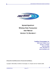
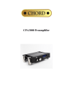
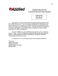
1
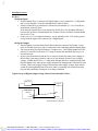
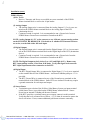
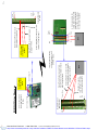
FGRIO System User Manual
Version 1
FGRIO Master
FGRIO Slave
FGR2-IO Slave
FGRIO-M
FGRIO-S
FGR2-IOS-CE-U
Remote Site Products - 1-888-532-2706 - www.remotesiteproducts.com
http://www.remotesiteproducts.com/p-20029-FreeWave-FGRIO-S-Radio-Board-Level-900-MHz-I/O-Slave-Radio.aspx
UL Notification:
This equipment is suitable for use in Class I, Division 2, Groups A, B, C, and D or nonhazardous locations only.”
Warning—Explosion Hazard—Substitution of components may impair suitability for
Class I, Division 2.
The diagnostics port and cable do not have a latching connector and cannot be
used in a hazardous location.
Remote Site Products - 1-888-532-2706 - www.remotesiteproducts.com
http://www.remotesiteproducts.com/p-20029-FreeWave-FGRIO-S-Radio-Board-Level-900-MHz-I/O-Slave-Radio.aspx
Table of Contents
Description…………………………………………………………….….……….…………...5
Glossary …………………………………………………….….…………………………..5-6
Diagrams …..………………………………………….….……………………………...….7-8
LEDs ………………………………………………….….………………………...…………9
Set Up with Hyperterminal…..…………..………….…..……………...……………...….9-17
FGRIO Master………………………………..………....…………………………9-13
Operation Mode ………………………….…………….……………………..9
Call Book ..……...……………………………..………………….………...10
Radio Transmission Characteristics..……….…..……………….…………10
Max and Min Packet Sizes ………………...………………………...10
RF Data Rate ……………………...………………………………….10
Multipoint Parameters …………………...………………………………....10
Number of Repeaters……………...……………………………….....10
Network ID ………………………………………………………...….10
FGRIO Setup ...………………..…………………………………...……..11-13
IO Slave………………………………………….……………….……………….14-17
Operation Mode ………….………………………………………………….14
Call Book ……...……………………………………………………………..14
Radio Transmission Characteristics …………….………….……..……14-15
Max and Min Packet Sizes ……………………………………….14-15
RF Data Rate ………………………….………………………..…….15
Retry Timeout ………………………..………………………….……15
Multipoint Parameters ……………………..………………………….…….15
Number of Repeaters ………………..…………………….………….15
Network ID …………………………..………………………………..15
FGRIO Setup………………………..……………………...….……….....16-17
Set Up with Tool Suite………..…………..………..……………………………...………18-26
FGRIO Master…………………………..……………………………………..….18-21
Operation Mode ………………..……………………………………….…....18
Call Book……………………………………..……………………………….18
Radio Transmission Characteristics …………..…………………..…….….19
Max and Min Packet Sizes …………….……...……………………...19
RF Data Rate ……………………….………...……………………….19
Multipoint Parameters…………………………………...………………19-20
Number of Repeaters…………………………………...…………….19
Remote Site Products - 1-888-532-2706 - www.remotesiteproducts.com
http://www.remotesiteproducts.com/p-20029-FreeWave-FGRIO-S-Radio-Board-Level-900-MHz-I/O-Slave-Radio.aspx
Table of Contents
Network ID…………………………………………………...……….19
IO Settings……………………………………………………...………...20-21
Enable FGRIO……………………………………………...……….. 20
Mapping……………………………………………….……...……….20
Time Out ……………………………………………..…...…………..21
Sensor Power………………………………………...………….…….21
IO Slave……………………………………………,,,…………………………….22-26
Operation Mode……….………………………...……………………..…….22
Call Book…………………………………...………………………………...22
Radio Transmission Characteristics………………….…………...………..23
Max and Min Packet Sizes ……………...……….………...………...23
RF Data Rate ……………………………………………...………….23
Retry Timeout ………………………………………..…..…………..23
Multipoint Parameters………………………………………..………….….24
Number of Repeaters………………………..……………..….……...24
Network ID……………………………………..………...…………...24
Wire Replacement…………………………………….………………….25-26
Digital Out 1 and Digital Out 2……………………….……………...25
Digital Def 1 and Digital Def 2……………………….………………25
Default Delay………………………………………………………….25
Digital Input Pull Up/Down…………………………….……...……..25
Installation………….…………………………………….……………………………….26-34
IO Slave……………………………………………..………………………...…..26-32
B+ …………………………………………… …………….……….……….26
1-5 Volt Sensor ……………………………..……………………………26-27
4-20 Milliamp Sensor …………………………………………… ….….27-28
1-5 Volt Sensor, Analog Input 3 or Analog Input 4…….…… …..…...28-30
Signal Levels and Accuracy……………………… ………...…......28
Signal Coupling for Analog Input 3 and Analog Input 4 ...…29-30
4-20 Milliamp Sensor, Analog Input 3 or Analog Input 4…… ……...30-31
Digital Input
…………………………………….…………………..32
Digital Output …………………………… …..……………………………32
FGRIO Master ……………………………………..…… …………………….33-34
Rx, Tx, B+ ……………………………… …...…………………………..33
Analog Output ..….……………………………..………… ………………33
Remote Site Products - 1-888-532-2706 - www.remotesiteproducts.com
http://www.remotesiteproducts.com/p-20029-FreeWave-FGRIO-S-Radio-Board-Level-900-MHz-I/O-Slave-Radio.aspx
Table of Contents
Digital Output …………………………………………….…………………33
Digital Input …………………………………….……………….………….23
Sensor Power………………………..……………………………………33-34
Link Alarms ………………………………………………………..………..34
Frequently Asked Questions ... …….……………………………….……….……….…34-35
Wiring Diagram …………………………………………………………………………….36
Specifications …………………………...……………………………………………….27-39
Remote Site Products - 1-888-532-2706 - www.remotesiteproducts.com
http://www.remotesiteproducts.com/p-20029-FreeWave-FGRIO-S-Radio-Board-Level-900-MHz-I/O-Slave-Radio.aspx
Description
This is an addendum to the Spread Spectrum Wireless Data Transceiver User Manual. It covers
details applicable specifically to using the FreeWave FGRIO Master and Slave modems. Please
use this addendum in conjunction with the User Manual.
The FreeWave Technologies FGRIO System provides outstanding performance and versatility
in wireless transmission of process-control signals. FGRIO offers “transparent” acquisition,
transport and reconstruction of analog, digital and power signals, eliminating the need for associated buried wiring. The RTU requires no altered programming. The FGRIO is Class 1 Div 2
approved and is lower-cost and provides better signal integrity than vulnerable wiring.
The FGRIO System is based upon wireless RF Technologies. RF is subject to interference and
communication interruptions. It should not be expected, therefore, to provide 100% communication, 100% of the time. The FGRIO System should not be used without proper provisions to
ensure safety upon loss of radio communications.
Glossary
FGRIO Master– FreeWave wireless radio transceiver that operates as a Master for up to 4
FGRIO or FGR2-IO Slaves, and can operate as a Slave in a point to multipoint network. The
FGRIO Master can receive over air a total of 4 analog input signals and 4 digital input signals
from up to 4 FGRIO or FGR2-IO Slaves. It can also transmit up to 4 digital output signals
over air to the FGRIO or FGR2-IO Slaves. The FGRIO Master does not operate as a Slave/
Repeater in the SCADA system.
FGRIO Slave – FreeWave wireless radio transceiver that accepts up to a total of 4 input signals
from sensors, then transmits these signals over air to the FGRIO Master. Two of the 4 available
input signals can only be transmitted as analog signals and are labeled as Analog Input 1 and
Analog Input 2 on the Slave’s terminal block. The other two input signals may be either analog
or digital inputs, depending on the user’s needs. The FGRIO Slave can also receive over air 2
digital output signals and a sensor power control signal from the FGRIO Master.
FGR2-IO Slave – New generation FreeWave wireless radio transceiver that accepts up to a total of 4 input signals from sensors, then transmits these signals over air to the FGRIO Master.
Two of the available 4 input signals can only be transmitted as analog signals and are labeled as
Analog Input 1 and Analog Input 2 on the Slave’s terminal block. The other two input signals
may be either analog or digital inputs, depending on the user’s needs. The FGR2-IO Slave can
also receive over air 2 digital output signals and a sensor power control signal from the FGRIO
Master. The FGR2-IO has a line-of-sight range of 60 miles, compared to the 2 mile line-ofsight range of the FGRIO Slave.
A note about terminology: The phrase ‘FGRIO System’, when used in this manual, will refer
to any system that uses an FGRIO Master in conjunction with either FGRIO or FGR2-IO
Slaves. IO Slave will refer to either an FGRIO Slave or an FGR2-IO Slave.
Remote Site Products - 1-888-532-2706 - www.remotesiteproducts.com
http://www.remotesiteproducts.com/p-20029-FreeWave-FGRIO-S-Radio-Board-Level-900-MHz-I/O-Slave-Radio.aspx
Glossary (cont.)
Analog Circuit– An electronic circuit that operates with currents and voltages that vary continuously with time and have no abrupt transitions between levels. Temperatures, pressures, or flow
rates are all represented by analog circuits.
Digital Circuit– An electronic circuit that functions as though currents or voltages exist only at
one of a set of discrete levels, all transitions between levels being ignored. The states of a digital
circuit are often referred to as on or off, high or low.
VSNS- This is screw terminal # 7 on the IO Slave. This is an output used to power sensors/
transmitters. The maximum output voltage of this terminal is 20VDC for the FGRIO-S and
30VDC for the FGR2-IOS-C-U and FGR2-IOS-CE-U
Remote Site Products - 1-888-532-2706 - www.remotesiteproducts.com
http://www.remotesiteproducts.com/p-20029-FreeWave-FGRIO-S-Radio-Board-Level-900-MHz-I/O-Slave-Radio.aspx
Diagrams
Diagnostic Port
Fig. 1
FGRIO Master Layer
Terminal Block
10 pin Header
FGRIO Master
Terminal Block
Ground
Rx Data
Tx Data
B+ In
Fig. 2
•
•
•
•
•
•
•
•
•
•
•
•
•
•
•
•
Sensor Power
Digital Input 1
Digital Input 2
Digital Input 3
Digital Input 4
Analog Output 1
Analog Output 2
Analog Output 3
Analog Output 4
Digital Output 1
Digital Output 2
Digital Output 3
Digital Output 4
Link Alarm
CMD Alarm
Not Used
Remote Site Products - 1-888-532-2706 - www.remotesiteproducts.com
http://www.remotesiteproducts.com/p-20029-FreeWave-FGRIO-S-Radio-Board-Level-900-MHz-I/O-Slave-Radio.aspx
Diagrams (cont.)
Fig. 3
FGRIO/FGR2-IO Slave
FGR2-IO-CE-U
Pin #1
Terminal Block
Connector
Diagnostics Port
DB9 Data port
Terminal Block
Connector
Pin #1
Diagnostics Port
10 Pin Header
Fig. 4
FGRIO Slave
Terminal Block
•
•
•
•
•
•
•
•
•
•
•
•
12-Ground
11-B+ IN
10-Analog Input 2
9-Ground
8-Analog Input 1
7-VSNS/Analog Out 1
6-Ground
5-Digital Output 2
4-Digital Output 1
3-Ground
2-Digital Input 2 OR
Analog Input 4*
1-Digital Input 1 OR
Analog Input 3*
FGR2-IO Slave
Terminal Block
•
•
•
•
•
•
•
•
•
•
•
•
12-Ground
11-B+ IN
10-Analog Input 2
9-Ground
8-Analog Input 1
7-VSNS/Analog Out 1
6-Analog Output 2*
5-Digital Output 2
4-Digital Output 1
3-Ground
2-Digital Input 2 OR
Analog Input 4*
1-Digital Input 1 OR
Analog Input 3*
Note: *Analog Output 2 is not available in the IO Wire Replacement mode. Analog Inputs 3 and 4 are 03.3VDC inputs. See wiring diagrams on pages 29-31 for details.
Remote Site Products - 1-888-532-2706 - www.remotesiteproducts.com
http://www.remotesiteproducts.com/p-20029-FreeWave-FGRIO-S-Radio-Board-Level-900-MHz-I/O-Slave-Radio.aspx
LEDs
The LEDs should have the following appearance when the IO Slave is linked to the FGRIO Master in a FGRIO
Stand Alone Network:
FGRIO Master
FGRIO Slave
Carrier Detect
(CD)
Transmit
(TX)
Clear to
Send (CTS)
Carrier Detect (CD)
Transmit
(TX)
Clear to
Send (CTS)
Solid green
bright
Solid red
dim
BLINKING
red
Blinking
green
Blinking red
Blinking red
The LEDs on the FGRIO Master and IO Slave should have the following appearance when the FGRIO Master is
linked to the FGR Network Master and the IO Slave is linked to the FGRIO Master:
FGRIO Master
FGRIO Slave
Carrier Detect
(CD)
Transmit
(TX)
Clear to
Send (CTS)
Carrier Detect (CD)
Transmit
(TX)
Clear to
Send (CTS)
Solid green
bright
Solid red
dim
FLICKERING
red
Blinking
green
Blinking red
Blinking red
Set Up with HyperTerminal
FGRIO Master– In order for the FGRIO System to function properly, the following settings
must be programmed. For all other settings not listed below, please refer to the User Manual.
(0) Operation Mode
(3) Point to MultiPoint Slave– Choose this setting when the FGRIO System is being integrated into an FGR Serial Network. The IO functionality is turned on in Menu 9–
FGRIO Set Up, in HyperTerminal.
Note: Setting (E), FGRIO Master, should only be selected when the FGRIO System is operating independently of an FGR FreeWave Network.
Fig. 5
Use this Operation Mode when the
FGRIO Master is being integrated into
an FGR Serial Network
Use this Operation Mode when the
FGRIO System is Stand Alone
Remote Site Products - 1-888-532-2706 - www.remotesiteproducts.com
http://www.remotesiteproducts.com/p-20029-FreeWave-FGRIO-S-Radio-Board-Level-900-MHz-I/O-Slave-Radio.aspx
Set Up with HyperTerminal (cont.)
FGRIO Master
(2) Call Book– IO Slaves’ serial numbers must be programmed in the FGRIO Master’s Call
Book. In addition, the Network ID must be set to the same ID as the rest of the network.
Programming both the Call Book and Network ID settings is unique to the FGRIO System
and must be done for both integrated and stand alone applications.
(3) Radio Transmission Characteristics
(1) Max Packet Size and (2) Min Packet Size– The FGRIO System requires a minimum
combined packet size of 48 Bytes. The following is a list of the available packet sizes that can
be used.
Fig. 6
Combined Packet Size Definition with RF Date Rate of 3
Max Setting
Min Setting
0
1
2
3
4
5
6
7
8
9
0
8
24
40
56
72
88
104
120
136
152
1
12
28
44
60
76
92
108
124
140
156
2
16
32
48
64
80
96
112
128
144
160
3
20
36
52
68
84
100
116
132
148
164
4
24
40
56
72
88
104
120
136
152
168
5
28
44
60
76
92
108
124
140
156
172
6
32
48
64
80
96
112
128
144
160
176
7
36
52
68
84
100
116
132
148
164
180
8
40
56
72
88
104
120
136
152
168
184
9
44
60
76
92
108
124
140
156
172
188
(4) RF Data Rate– The RF Data Rate must be set to 3 when using the FGRIO System. This
is for applications that are stand alone or when integrated into an existing FGR network.
MultiPoint Parameters(0) Number Repeaters– This setting must be set to 1 for all FGR and IO radios in the
Network.
(6) Network ID– In addition to entering the IO Slaves’ serial numbers in the Call
Book, the Network ID being used for the Network must be set from 1-4095. (Do NOT
use 255). Programming both the Call Book and Network ID settings is unique to the
FGRIO System and must be done for both integrated and stand alone applications.
Note: The FGRIO Master does not function as a Slave/Repeater in the SCADA network.
Remote Site Products - 1-888-532-2706 - www.remotesiteproducts.com
http://www.remotesiteproducts.com/p-20029-FreeWave-FGRIO-S-Radio-Board-Level-900-MHz-I/O-Slave-Radio.aspx
Set Up with HyperTerminal (cont.)
FGRIO Master
(9) FGRIO Setup– Outputs on the FGRIO Master are mapped to inputs on the IO Slave.
Fig. 7
Remote Site Products - 1-888-532-2706 - www.remotesiteproducts.com
http://www.remotesiteproducts.com/p-20029-FreeWave-FGRIO-S-Radio-Board-Level-900-MHz-I/O-Slave-Radio.aspx
Set Up with HyperTerminal (cont.)
FGRIO Master
(9) FGRIO Setup (cont.)
(0) FGRIO – Must be set to 1 to enable I/O functions.
(1) to (8) – To map the FGRIO Master outputs to the correct IO Slave inputs, use
the following steps:
1) Select which IO Slave you are mapping to the FGRIO Master. Note the Master’s
Call Book Entry # that lists this IO Slave’s serial number.
2) Next, determine which analog or digital input from the IO Slave radio you wish to
map to the FGRIO Master. This could be Analog Input(AI)#1, AI#2, AI#3, AI#4, or
Digital Input(DI)#1, or DI#2, depending on which sensor(s) the Slave will be connected to.
3) Using the following table, find the intersection between the Master’s Call Book
Entry # (found in step 1) and the selected input from the Slave (found in step 2).
Note the number listed at this intersection.
4) Go to Menu 9, FGRIO Setup (Figure 7). Select which Master’s output you would
like to “connect” to the input from the Slave. At the flashing curser, enter the number
to the left of the selected output. Next enter the number found in step 3. This number should be displayed to the right of the selected output.
Fig. 8
AI#1
AI#2
AI#3
AI#4
DI#1
DI#2
FRGIO-M Call Book
Entry #0
1
2
9
10
1
2
FRGIO-M Call Book
Entry #1
3
4
11
12
3
4
FRGIO-M Call Book
Entry #2
5
6
13
14
5
6
FRGIO-M Call Book
Entry #3
7
8
15
16
7
8
EXAMPLE
To map Analog Output 1 of the FGRIO Master to Analog Input 2 of the IO Slave (serial # 9300004), entry (5) in the FGRIO Setup menu will have a value of 2. This is calculated by first
checking the Call Book entry # of IO Slave #930-0004 (See Figure 9, next page). The entry # is
0. Next, go to the table above, find call book entry # 0, then go to the column for IO Slave Analog Input #2. The value listed is 2. A 2 will be entered for Analog Output #1 of the FGRIO
Master.
Remote Site Products - 1-888-532-2706 - www.remotesiteproducts.com
http://www.remotesiteproducts.com/p-20029-FreeWave-FGRIO-S-Radio-Board-Level-900-MHz-I/O-Slave-Radio.aspx
Set Up with HyperTerminal (cont.)
FGRIO Master
Fig. 9
(9) FGRIO Setup (cont.)
(9) TimeOut– 0-255. This setting determines the amount of time to wait before issuing a
Link Alarm due to loss of communication between the FGRIO Master and IO
Slave. A setting of 1 = 1/6 second
6 = 1 second
42 = 7 seconds
252 = 42 seconds
(A) Sensor Power– 0 or 1. A setting of 0 supplies continuous power to the sensor at the
IO Slave. A setting of 1, “Gated”, is used when the RTU provides a switched
power output to control powering the sensors at the IO Slave and analog outputs of
the FGRIO Master on and off.
Remote Site Products - 1-888-532-2706 - www.remotesiteproducts.com
http://www.remotesiteproducts.com/p-20029-FreeWave-FGRIO-S-Radio-Board-Level-900-MHz-I/O-Slave-Radio.aspx
Set Up With HyperTerminal (cont.)
IO Slave- In order for the FGRIO System to function properly, the following settings must be
programmed. For all other settings not listed below, please refer to the User Manual.
(0) Operation Mode
(E) FGRIO Slave
Fig. 10
(2) Call Book– The FGRIO Master’s serial number must be programmed as entry #0 in the IO
Slave’s Call Book. Set “Entry to Call” to 0. In addition, the Network ID must be set to the
same ID as the rest of the network. Programming both the Call Book and Network ID settings is unique only to the FGRIO System and must be done for both integrated and stand
alone applications.
(3) Radio Transmission Characteristics
(1) Max Packet Size and (2) Min Packet Size– The FGRIO System requires a minimum
combined packet size of 48 Bytes. The following is a list of the available packet sizes
that can be used (Figure 11, next page).
Remote Site Products - 1-888-532-2706 - www.remotesiteproducts.com
http://www.remotesiteproducts.com/p-20029-FreeWave-FGRIO-S-Radio-Board-Level-900-MHz-I/O-Slave-Radio.aspx
Set Up with HyperTerminal (cont.)
IO Slave
(3) Radio Transmission Characteristics (cont.)
Fig. 11
Combined Packet Size Definition with RF Date Rate of 3
Max Setting
Min Setting
0
1
2
3
4
5
6
7
8
9
0
8
24
40
56
72
88
104
120
136
152
1
12
28
44
60
76
92
108
124
140
156
2
16
32
48
64
80
96
112
128
144
160
3
20
36
52
68
84
100
116
132
148
164
4
24
40
56
72
88
104
120
136
152
168
5
28
44
60
76
92
108
124
140
156
172
6
32
48
64
80
96
112
128
144
160
176
7
36
52
68
84
100
116
132
148
164
180
8
40
56
72
88
104
120
136
152
168
184
9
44
60
76
92
108
124
140
156
172
188
(4) RF Data Rate– The RF Data Rate must be set to 3 when using the FGRIO System. This
is for applications that are stand alone or when integrated into an existing FGR network.
(8) Retry Timeout– By lowering the Retry Timeout, the inactive link time between the
FGRIO Master and IO Slave can be reduced when going from autonomous mode to
connecting back to the FGR Network. If the Network Master goes down, the FGRIO
Master and Slave will continue to operate in autonomous mode. When the Network
Master comes back up, the FGRIO Master will break the link with the IO Slave to
reestablish a link with the Network Master. Once the FGRIO Master is linked to the
Network Master, then the IO Slave will be able to link back to the FGRIO Master.
With a lower Retry Timeout setting, it will take less time for the IO Slave to link to
the FGRIO Maser.
(5) MultiPoint Parameters(0) Number Repeaters- This setting must be set to 1 for all FGR and IO radios in the
Network.
(6) Network ID– In addition to entering the FGRIO Master’s serial number in the Call
Book, the Network ID being used for the Network must be set from 1-4095 (Do NOT use
255). Use the same Network ID for the IO Slave as was used for the FGRIO Master.
Programming both the Call Book and Network ID settings is unique to the FGRIO
System and must be done for both integrated and stand alone applications.
Remote Site Products - 1-888-532-2706 - www.remotesiteproducts.com
http://www.remotesiteproducts.com/p-20029-FreeWave-FGRIO-S-Radio-Board-Level-900-MHz-I/O-Slave-Radio.aspx
Set Up with HyperTerminal (cont.)
IO Slave
(9) FGRIO Setup
(0) Default Delay, the value set is in .28 second units. This sets the time duration that will
pass, after a loss of communication, before the radio enters default condition. e.g. A value of
36 = 36*0.28 seconds = 10.08 seconds.
(1) Digital Out1– Select the desired FGRIO Master Digital Input # (1-4) to control the
IO Slave Digital Output # 1.
(2) Digital Out2– Select the desired FGRIO Master Digital Input # (1-4) to control the
IO Slave Digital Output # 2.
(3) Digital Def 1 – Select the desired IO Slave Output Default at power-on and link failure.
0= Open Drain output ON (Conducting to GND, 2 Amps max)
1= Open Drain output OFF (Non-Conducting)
2= Make no change in state.
(4) Digital Def2- Select the desired IO Slave Output Default at power-on and link failure.
0= Open Drain output ON (Conducting to GND, 2 Amps max)
1= Open Drain output OFF (Non-Conducting)
2= Make no change in state.
Note: If programming a DO to turn on after loss of link, ensure that the energized device
can sustain the state undamaged in case the loss in lengthy.
(5) IO Modbus– This menu option must be set to “Disabled” when using a FGRIO network
configuration.
(E and F) DI1 Pull Up/Down- Options E and F control power-up states of the internal resistor (10Kohms) connected to the DIs. They can pull up, such as when using a closed-contactto-GND switch input, pull down so that unused inputs read “0” as DIs or ~0 as auxiliary analogs, or float to not load analog inputs.
(I and J) AI(DI1) and AI(DI2) Filter do not apply in the FGRIO network.
Note: Both of the IO Slave Digital Outputs may be driven by the same FGRIO
Master Input.
Remote Site Products - 1-888-532-2706 - www.remotesiteproducts.com
http://www.remotesiteproducts.com/p-20029-FreeWave-FGRIO-S-Radio-Board-Level-900-MHz-I/O-Slave-Radio.aspx
Set Up with HyperTerminal (cont.)
(9) FGRIO Setup (cont.)
Fig. 12
Remote Site Products - 1-888-532-2706 - www.remotesiteproducts.com
http://www.remotesiteproducts.com/p-20029-FreeWave-FGRIO-S-Radio-Board-Level-900-MHz-I/O-Slave-Radio.aspx
Set Up with Tool Suite
FGRIO Master– In order for the FGRIO System to function properly, the following settings
must be programmed. For all other settings not listed below, please refer to the User Manual.
0) Set Operation Mode Tab-(Figure 13)
Point to MultiPoint Slave– Choose this setting when the FGRIO System is being integrated into an FGR FreeWave Network. The IO functionality is turned on under the IO Settings tab.
Note: Setting (E), FGRIO Master, should only be selected when the FGRIO System is operating independently of an FGR FreeWave Network.
Figure 13
2) Call Book TabEnter the serial number for each IO Slave, for a maximum of up to four (4) IO-Slave Radios.
Remote Site Products - 1-888-532-2706 - www.remotesiteproducts.com
http://www.remotesiteproducts.com/p-20029-FreeWave-FGRIO-S-Radio-Board-Level-900-MHz-I/O-Slave-Radio.aspx
Set Up with Tool Suite (cont.)
3) Radio Transmission Characteristics Tab-(Figure 14)
Max Packet Size and Min Packet Size– The FGRIO System requires a minimum combined packet size of 48 Bytes. See Figure 6 (pg. 10) for a list of available packet sizes.
RF Data Rate– The RF Data Rate must be set to “Normal” (3) when using the FGRIO System. This is for applications that are stand alone or when integrated into an existing FGR
network.
Figure 14
Figure 14
5) MultiPoint Parameters Tab– (Figure 15)
Number Repeaters– This setting must be set to 1 for all FGR and FGRIO radios in the
Network.
Network ID– In addition to entering the serial numbers of the IO Slaves in the Call Book,
the Network ID being used for the Network must be set from 1-4095 (Do NOT use 255).
Programming both the Call Book and Network ID settings is unique to the FGRIO System
and must be done for both integrated and stand alone applications.
Note: The FGRIO Master does not function as a Slave/Repeater in the SCADA network.
Remote Site Products - 1-888-532-2706 - www.remotesiteproducts.com
http://www.remotesiteproducts.com/p-20029-FreeWave-FGRIO-S-Radio-Board-Level-900-MHz-I/O-Slave-Radio.aspx
Set Up with Tool Suite (cont.)
5) MultiPoint Parameters Tab (cont.)
Figure 15
FGRIO Master
(9) IO Settings Tab- (Figure 16). This tab allows the user to map the inputs of the IO-Slave to
the outputs of the FGRIO-Master.
Enable FGRIO– To turn on the IO functionality in the FGRIO-M, the “Enable FGRIO”
drop down box must be set to enabled.
Mapping– In the IO Settings tab of the FGRIO-M, the FGRIO-M outputs are mapped to the
IO-Slave inputs. To map, select the appropriate Slave input from the drop down box next to
the master’s output.
Note: The slaves are labeled by their position in the masters Call Book. E.g. Slave 0 refers to
the serial number in entry to call 0.
Remote Site Products - 1-888-532-2706 - www.remotesiteproducts.com
http://www.remotesiteproducts.com/p-20029-FreeWave-FGRIO-S-Radio-Board-Level-900-MHz-I/O-Slave-Radio.aspx
Set Up with Tool Suite (cont.)
FGRIO Master
(9)IO Settings Tab– (cont.)
Time Out– 0-255. This setting determines the amount of time to wait before issuing a Link
Alarm due to loss of communication between the FGRIO Master and IO Slave.
A setting of 1 = 1/6 second
6 = 1 second
42 = 7 seconds
252 = 42 seconds
Sensor Power– Always On or Gated. A setting of Always On supplies continuous power to
the sensor at the IO Slave. A setting of Gated, is used when the RTU provides a switched
power output to control powering the sensors at the IO Slave and analog outputs of the
FGRIO Master on and off.
Figure 16
Remote Site Products - 1-888-532-2706 - www.remotesiteproducts.com
http://www.remotesiteproducts.com/p-20029-FreeWave-FGRIO-S-Radio-Board-Level-900-MHz-I/O-Slave-Radio.aspx
Set Up with Tool Suite (cont.)
IO Slave- In order for the FGRIO System to function properly, the following settings must be
programmed. For all other settings not listed below, please refer to the User Manual.
Set Operation Mode Tab- (Figure 17)
(E) FGRIO Slave– The modem mode of (E) IO-Slave (NOT IO-MODBUS) must be used in
the FGRIO System.
Figure 17
(2) Call Book– The FGRIO Master’s serial number must be programmed as entry #0 in the IO
Slave’s Call Book. Set “Entry to Call” to 0. In addition, the Network ID must be set to the
same ID as the rest of the network. Programming both the Call Book and Network ID settings is unique to the FGRIO System and must be done for both integrated and stand alone
applications.
Remote Site Products - 1-888-532-2706 - www.remotesiteproducts.com
http://www.remotesiteproducts.com/p-20029-FreeWave-FGRIO-S-Radio-Board-Level-900-MHz-I/O-Slave-Radio.aspx
Set Up with Tool Suite (cont.)
IO Slave
Transmission Characteristics-(Figure 18)
Max Packet Size and Min Packet Size– The FGRIO System requires a minimum combined packet size of 48 Bytes. See Figure 6 (pg. 10) for a list of available packet sizes that
can be used.
RF Data Rate - The RF Data Rate must be set to “Normal” (3) when using the FGRIO
System. This is for applications that are stand alone or when integrated into an existing FGR
network.
Retry Timeout– By lowering the Retry Timeout, the inactive link time between the FGRIO
Master and IO Slave can be reduced when going from autonomous mode to connecting
back to the FGR Network. If the Network Master goes down, the IO Master and Slave will
continue to operate in autonomous mode. When the Network Master comes back up, the
FRGIO Master will break the link with the IO Slave to reestablish a link with the Network
Master. Once the FGRIO Master is linked to the Network Master, then the IO Slave will be
able to link back to the FGRIO Master. With a lower Retry Timeout setting, it will take less
time for the IO Slave to link to the FGRIO Master.
Figure 18
Remote Site Products - 1-888-532-2706 - www.remotesiteproducts.com
http://www.remotesiteproducts.com/p-20029-FreeWave-FGRIO-S-Radio-Board-Level-900-MHz-I/O-Slave-Radio.aspx
Set Up with Tool Suite (cont.)
MultiPoint Parameters Tab-(Figure 19)
Number Repeaters- This setting must be set to “On” for all FGR and IO radios in the Network.
Network ID– In addition to entering the FGRIO Master’s serial number in the Call Book,
the Network ID being used for the Network must be set from 1-4095. (Do NOT use 255).
Programming both the Call Book and Network ID settings is unique to the FGRIO System
and must be done for both integrated and stand alone applications.
Figure 19
Remote Site Products - 1-888-532-2706 - www.remotesiteproducts.com
http://www.remotesiteproducts.com/p-20029-FreeWave-FGRIO-S-Radio-Board-Level-900-MHz-I/O-Slave-Radio.aspx
Set Up with Tool Suite (cont.)
IO Slave
(9) Wire Replacement Tab (Figure 20)
Digital Out 1 – Select the desired FGRIO Master Digital Input # (1-4) to control the
IO Slave Digital Output # 1.
Digital Out 2– Select the desired FGRIO Master Digital Input # (1-4) to control the
IO Slave Digital Output # 2.
Digital Out 1 Default – Select the desired IO Slave Output Default at power-on and link
failure.
Open Drain output ON (Conducting to GND, 2 Amps max)
Open Drain output OFF (Non-Conducting)
Make no change in state.
Digital Out 2 Default - Select the desired IO Slave Output Default at power-on and link
failure.
Open Drain output ON (Conducting to GND, 2 Amps max)
Open Drain output OFF (Non-Conducting)
Make no change in state.
Note: If programming a DO to turn on after loss of link, ensure that the energized device
can sustain the state undamaged in case the loss in lengthy.
Default Delay - This value is set in .28 second units. This sets the time duration that will
pass, after a loss of communication, before the radio enters default condition. E.g. A value
of 36 = 36*0.28 seconds = 10.08 seconds.
DI1 Pull Up/Down– These options control power-up states of the internal resistor
(10Kohms) connected to the DIs. They can pull up, such as when using a closed-contact-toGND switch input, pull down so that unused inputs read “0” as DIs or ~0 as auxiliary analogs, or float to not load analog inputs.
Note: Both of the IO Slave Digital Outputs may be driven by the same FGRIO
Master Input.
Remote Site Products - 1-888-532-2706 - www.remotesiteproducts.com
http://www.remotesiteproducts.com/p-20029-FreeWave-FGRIO-S-Radio-Board-Level-900-MHz-I/O-Slave-Radio.aspx
Set Up with Tool Suite (cont.)
Figure 20
Installation
IO Slave
(1) B+ IN
Screw Terminal #11 (B+ In) on the terminal block of the IO Slave is the raw power for
the radio. This terminal is directly connected to Pin # 1 on the 10 pin white header of
the IO Slave. Either one can be used to power the radio.
(2) 1-5 Volt Sensor
• For connection to either Analog Input 1 or Analog Input 2, the 1-5 volt sensor can
be wired to the IO Slave with a 3 wire connection.
• The Sensor Ground Wire can be connected to Ground Screw Terminal #3, 9, or 12
on the terminal block of the IO Slave.
•The Sensor Power Wire is connected to the VSNS screw terminal #7 on the terminal block of the IO Slave. Rated total current draw from VSNS is 40 mA or less.
•Sensor Output Wire is connected to Analog Input 1 screw terminal #8 or Analog Input 2 screw terminal #10 on the terminal block of the IO Slave.
Remote Site Products - 1-888-532-2706 - www.remotesiteproducts.com
http://www.remotesiteproducts.com/p-20029-FreeWave-FGRIO-S-Radio-Board-Level-900-MHz-I/O-Slave-Radio.aspx
Installation
IO Slave
(2) 1-5 Volt Sensor (cont.)
• Sensor Output Wire is connected to Analog Input 1 screw terminal # 8 or Analog Input 2 screw terminal # 10 on the terminal block of the IO Slave.
(3) 4-20 Milliamp Sensor (Figures 21-22)
• Consists of a 2 wire connection from the Sensor to the IO Slave.
• An external resistor (typically 249 Ohms) is required to convert 4-20 milliamps to 15 volts. The resistor goes from the desired Analog Input to Ground screw terminals
on the terminal block of the IO Slave.
• Sensor Power Supply (High) Wire is connected to VSNS screw terminal #7 on the
terminal block of the IO Slave.
• Sensor Output (Low) Wire is connected to the same Analog Input as the resistor on
the terminal block of the IO Slave.
Example of one 4-20 milliamp sensors connecting to the terminal block of the IO Slave:
(Figures 21-22)
Figure 21
FGRIO-S Wiring diagram
Low Wire
Sensor #1
High
Wir
Resistor for
Sensor # 1
e
Resistor for
Sensor # 2
Low Wire
Sensor #2
High W
ire
•
•
•
•
•
•
•
•
•
•
•
•
12-Ground
11-B+ IN
10-Analog Input 2
9-Ground
8-Analog Input 1
7-VSNS
6-Ground
5-Digital Output 2
4-Digital Output 1
3-Ground
2-Digital Input 2 OR
Analog Input 4*
1-Digital Input 1 OR
Analog Input 3*
Remote Site Products - 1-888-532-2706 - www.remotesiteproducts.com
http://www.remotesiteproducts.com/p-20029-FreeWave-FGRIO-S-Radio-Board-Level-900-MHz-I/O-Slave-Radio.aspx
Installation (cont.)
Figure 22
FGR2-IOS Wiring diagram
Low Wire
Sensor #1
Hig
hW
ire
Resistor for
Sensor # 1
Resistor for
Sensor # 2
Low Wire
Sensor #2
High Wire
•
•
•
•
•
•
•
•
•
•
•
•
12-Ground
11-B+ IN
10-Analog Input 2
9-Ground
8-Analog Input 1
7-VSNS/Analog Out 1
6-Analog Output 2*
5-Digital Output 2
4-Digital Output 1
3-Ground
2-Digital Input 2 OR
Analog Input 4*
1-Digital Input 1 OR
Analog Input 3*
Note: *Analog Output 2 is not available in the IO Wire Replacement mode. Analog inputs 3 and
4 are 0-3.3VDC inputs. See wiring diagrams on pages 29-31 for details.
(3) 1-5 Volt Sensor, Analog Input 3 or Analog Input 4
With FGRIO-S firmware 2.65IO or FGR2-IOS firmware 9.7, and FGRIO-M firmware 2.65, the
Digital Inputs (DIs) of the FGRIO-S or FGR2-IOS may be digitized to 10 bit resolution and
mapped to Analog Outputs (AOs) on the FRGIO-M. This allows up to 4 analog transducers to
be connected to a single remote FGRIO-S or FGR2-IOS radio.
A. Signal Levels and Accuracy.
The existing AIs at screw terminal #8 and screw terminal #10 are usable with .1V to 5.625V input voltages (compatible with most 1-5V and 4-20mA transmitters) and load the input with
about 100Kohm to GND. They also offer accuracy of +/-.1% with 16 bit resolution and are
therefore recommended for the most critical variables in a system.
In comparison, the new AIs formed from the DIs at screw terminal #1 and screw terminal #2 are
directly usable with signals only from .1V to 2.812V in wire replacement mode. Input loading
can be selected as 10Kohm to GND or unloaded (>1Megohm). Accuracy is within +/-.25% and
resolution is 10 bits. The next section describes methods to best apply inputs to them.
Remote Site Products - 1-888-532-2706 - www.remotesiteproducts.com
http://www.remotesiteproducts.com/p-20029-FreeWave-FGRIO-S-Radio-Board-Level-900-MHz-I/O-Slave-Radio.aspx
Installation (cont.)
B. Signal Coupling for Analog Input 3 and Analog Input 4.
1) Input Resistor
The IO Slave DIs have always provided an internal 10Kohm resistor pull-up to the radio’s 3.3V
logic supply. With new firmware 2.65IO in the FGRIO-S, or 9.7 in the FGR2-IOS, the resistor
can also be commanded (in the FGRIO Setup menu) to pull down to GND or “float” unconnected. As will be shown, these options are useful for connection of analog inputs.
2) Signal Level Reduction.
As stated above, the DI does not have sufficient voltage range for direct connection to typical
transducer outputs, so the input must be restricted. For signal replication, it is assumed the input
signal level will be halved, and the measured value sent to the FGRIO-M doubled, to achieve an
overall 1:1 signal reproduction.
3) VSNS Sensor Power
The switched voltage source at screw terminal #7 is designed to drive only two 4-20mA transmitters to full scale. Voltage output (1-5V) transmitters usually consume less current and may
allow up to 4 to be switched.
Below are two diagrams showing the connection of a 1-5V sensor to Analog Input 3: (Figures 23
and 24)
Figure 23
Remote Site Products - 1-888-532-2706 - www.remotesiteproducts.com
http://www.remotesiteproducts.com/p-20029-FreeWave-FGRIO-S-Radio-Board-Level-900-MHz-I/O-Slave-Radio.aspx
Installation (cont.)
Figure 24
(4) 4-20 Milliamp Sensor, Analog Input 3 or Analog Input 4
The same accuracy and signal level reduction considerations stated under section (3) 1-5 Volt
Sensor, Analog Input 3 or Analog Input 4, apply when using a 4-20 milliamp sensor. The
switched voltage source at screw terminal #7 is designed to drive only two 4-20mA transmitters
to full scale. If a system will use more than two, the additional transmitters must be powered
from a separate supply, such as directly from the battery or another DC supply.
On the next page are two diagrams showing the connection of a 4-20 milliamp sensor to Analog
Input 3 (Figures 25 and 26):
Remote Site Products - 1-888-532-2706 - www.remotesiteproducts.com
http://www.remotesiteproducts.com/p-20029-FreeWave-FGRIO-S-Radio-Board-Level-900-MHz-I/O-Slave-Radio.aspx
Installation (cont.)
(4) 4-20 Milliamp Sensor, Analog Input 3 or Analog Input 4
Figure 25
Figure 26
Remote Site Products - 1-888-532-2706 - www.remotesiteproducts.com
http://www.remotesiteproducts.com/p-20029-FreeWave-FGRIO-S-Radio-Board-Level-900-MHz-I/O-Slave-Radio.aspx
Installation (cont.)
IO Slave
(5) Digital Input
• Switch Output Wire is connected to Digital Input 1 screw terminal # 1 or Digital Input 2 screw terminal # 2 on the terminal block of the IO Slave.
• Switch Ground Wire is connected to Ground screw terminal # 3, 9 or 12 on the terminal block of the IO Slave.
If the Switch Ground Wire is not returned to the IO Slave, the potential difference
between the IO Slave Ground and the Dry Contact Closure (Switch) Ground should
not exceed 1 Volt.
• In the case of a 3 wire digital transducer, set up similarly to the 1-5V analog sensor,
except with the signal wire connected to a Digital Input.
(6) Digital Output
• Digital Output is an open drain field effect transistor connected to Ground. It connects to Ground when zero volts is connected to the controlling Master Digital Input.
• The current rating for Digital Output is 2 amps or less. The Digital Output will selfprotect if a current of more than 2 1/2 amps is drawn and automatically retry at .16
second intervals.
• If power on the Solenoid (end device) is not driven from the same power supply as
the IO Slave, that source must be equal to or less than the IO Slave power supply
voltage. Within the IO Slave, a 3 amp rated Schottky Diode is connected from each
Digital Output to the radio power supply terminal for clamping the Solenoid fly back
current. If the relay supply voltage exceeded the radio supply voltage, then current
would flow through that diode back to the radio, preventing coil current from shutting off and potentially causing an overvoltage condition.
Typical set up of Digital Output wiring between Solenoid and IO Slave:
Solenoid
Digital
Output 1
Solar Panel/
Battery
Vo
GND
B+
GND
Terminal Block of IO Slave
Remote Site Products - 1-888-532-2706 - www.remotesiteproducts.com
http://www.remotesiteproducts.com/p-20029-FreeWave-FGRIO-S-Radio-Board-Level-900-MHz-I/O-Slave-Radio.aspx
Installation (cont.)
FGRIO Master
(1) Rx, Tx, B+
• Receive, Transmit, and Power are available on screw terminals of the FGRIO
Master terminal block as well as the 10 pin header.
(2) Analog Output
• The Analog Output wire is connected from the Analog Output 1,2,3 or 4 screw terminal on the FGRIO Master terminal block to the Analog Input of the RTU
(destination device).
• Common Ground is required. It is recommended to run a Ground wire from an
FGRIO Master Ground screw terminal to Ground on the RTU.
NOTE: Analog Output is 1-5 V at low current, so any 4-20 mA current sensing resistor
on the RTU MUST BE REMOVED. If in doubt as to whether RTU-internal resistors
are active, test the link with a full scale input.
(3) Digital Output
• The Digital Output wire is connected from the Digital Output 1,2,3 or 4 screw terminal on the FGRIO Master terminal block to the Digital Input of the RTU (destination
device).
• Common Ground is required. It is recommended to run a Ground wire from the
FGRIO Master Ground screw terminal to Ground on the RTU.
NOTE: The Digital Output actively drives Low (.4V) and High (4.0V). Remove any
RTU input pull-up resistor, if less than 10 K ohms. Verify that signal levels meet the
RTU input requirements after connection to the RTU.
(4) Digital Input
• The RTU Digital Output Wire is connected to Digital Input 1,2,3 or 4 screw terminal
on the terminal block of the FGRIO Master. An internal 10Kohm pullup to +5V is
provided.
• The RTU Ground Wire is connected to any of the Ground screw terminals on the
terminal block of the FGRIO Master. Some RTUs use isolated I/O and may require
a ground connection for each input and output.
(5) Sensor Power
• To minimize power drain of the IO Slave Solar/Battery System, an input terminal
called Sensor Power is provided on the FGRIO Master terminal block. Sensor
Power has an internal 10 Kohm pull-down to Ground.
• If the RTU provides a switched sensor power output, connect it to this terminal.
Verify that the level at Sensor Power falls to < 1.0 V when de-asserted to ensure the
slaves will mirror. If not, connect additional pull-down resistance externally.
Remote Site Products - 1-888-532-2706 - www.remotesiteproducts.com
http://www.remotesiteproducts.com/p-20029-FreeWave-FGRIO-S-Radio-Board-Level-900-MHz-I/O-Slave-Radio.aspx
Installation (cont.)
FGRIO Master
(5) Sensor Power (cont.)
• The state of that sensor power will be mirrored at the IO Slave, powering the sensors
at the IO Slave on and off. It is necessary to change FGRIO Setup sub menu (A) to
“1” (Gated).
NOTE: The sensor power terminal both activates sensor power at the controlled
IO Slaves, and activates Analog Outputs at the FGRIO Master interface board,
when in Sensor Power “Gated” mode.
(6) Link Alarms
•
Link Alarm 1 is an alarm reflecting loss of communication on any path. A wire is
run from the Link Alarm 1 screw terminal to the Link Alarm screw terminal on the
RTU.
• Link Alarm 2 (CMD Alarm) indicates that a Digital Output or Sensor Power command was not carried out due to an over-current fault. A wire is run from the Link
Alarm 2 screw terminal to the Link Alarm screw terminal on the RTU.
NOTE: The terminal block of the FGRIO Master and Slave can accept a single
wire up to 16 gauge. Smaller wire is required for 2 wires, or wire + resistor into the
same screw terminal.
Frequently Asked Questions
Q: Can IO be used with a 1 watt radio?
A: The FGRIO Master operates as a standard FGR 1 watt radio with a 60 mile line of sight
range. The FGRIO Slave functions as an FGR radio with a 2 mile line of sight range. The
FGR2-IO Slave functions as an FGR radio with a 60 mile line of sight.
Q: Can the IO radios be repeated through our other radios to extend the range?
A: From the IO Slave to the FGRIO Master, repeaters cannot be used. From the FGRIO
Master to the rest of the existing network, repeaters can be used as they already are in
existing FreeWave networks. The FGRIO Master will not function as a Slave/Repeater
Q: Can the FGRIO Master operate as Slave/Repeater in the overall network?
A: The FGRIO Master currently does not have the capability to operate as a Slave/Repeater. It
does function as the Master to the IO Slave, and as a Slave to the rest of the network.
Remote Site Products - 1-888-532-2706 - www.remotesiteproducts.com
http://www.remotesiteproducts.com/p-20029-FreeWave-FGRIO-S-Radio-Board-Level-900-MHz-I/O-Slave-Radio.aspx
Frequently Asked Questions
Q: Can data be sent directly from the IO Slave to the Master of the FreeWave network?
A: No. The FGRIO system functions as wire replacement only. The IO Slave does not
have the capability of transmitting data directly to the Master of the network.
Q: What are the sizes of the FGRIO Master and Slave?
A: The board level IO Slave has the same footprint as the FGRO9 family. The board level IO
Slave dimensions are 127 mm (L) x 61 mm (W) x 15.5 mm (H). The FGRIO Master is a
standard footprint FGRO9 plus an IO Interface board on top, differing only in width at 2.75
inches. The dimensions of the FGRIO Master are 140 mm (L) x 70 mm (W) x 34 mm (H).
Q: What timing issues does IO introduce?
A: Although IO mimics a wired connection, the electronics and communication heartbeat
do cause some signal delay. The worst case delay for digital signals in either direction and
the Sensor Power command from FGRIO Master to IO Slave is 167 msec, assuming a
robust link. Worst case delay from FGRIO Master Sensor Power assertion to FGRIO Master
Analog Output refresh is 700 msec.
Remote Site Products - 1-888-532-2706 - www.remotesiteproducts.com
http://www.remotesiteproducts.com/p-20029-FreeWave-FGRIO-S-Radio-Board-Level-900-MHz-I/O-Slave-Radio.aspx
Remote Site Products - 1-888-532-2706 - www.remotesiteproducts.com
http://www.remotesiteproducts.com/p-20029-FreeWave-FGRIO-S-Radio-Board-Level-900-MHz-I/O-Slave-Radio.aspx
B+
GND
Terminal Block of
FGRIO Master
Screw Terminal # 12
Not
Used
RTU
Analog Output wire connects from
Analog Output 1 screw terminal to
Analog Input of the RTU
Sensor Ground Wire connects to
screw terminal # 9 Ground.
Screw
Terminal
#1
Screw
Terminal #12
B+
GND
RTU
Not
Used
Sensor
Power
A 2 wire connection for
analog output is made from
FGRIO Master to the RTU.
Sensor Power should also
be connected if available.
Sensor Output Wire connects to screw
Terminal Block of
terminal # 8 Analog Input 1.
IO Slave
Sensor Power Wire connects to screw
terminal # 7 VSNS.
1-5 V Pressure
or Temperature
Sensor
IO Slave transmits analog
and digital signals over air
to FGRIO Master.
Sensor Power Output connects from
Sensor Power screw terminal to Sensor
Power Output of RTU.
Screw Terminal # 1
1-5 V Pressure
or Temperature
Sensor
Ground wire connects
from Ground screw terminal to Ground on the RTU
Sensor Power
A 3 wire connection is
made from Sensor to
IO Slave
FGRIO Wiring Diagram
Technical Specifications
900 MHz Transceiver Specifications
Specification
Frequency
902 to 928 MHz
Transmit
Output Power
FGRIO-M: 5 mW to 1 W (+30 dBm) FGRIO-S: 100 mW (+20 dBm).
FRG2-IOS: 5mW to 1W (+30 dBm)
Range
2 miles Line Of Sight for FGRIO-S to FGRIO-M
60 miles Line of Sight for FGRIO-M to Network or FGRIO-M to FGR2-IOS
Modulation
Spread spectrum GFSK, 120 Kbps
Spreading method
Frequency hopping
Occupied bandwidth @ 60dB
230 kHz
Channel Spacing
230 kHz
Receive
Sensitivity
FGRIO-M or FGR2-IOS: -110 dBm at 10-4 bit error rate; FGRIO-S: -100 dBm
Selectivity
FGRIO-M or FGR2-IOS: -108 dBm at 10-6 bit error rate; FGRIO-S: -98 dBm
-20 dB at fcc ± 115 kHz
-60 dB at fcc ± 145 kHz
System gain
FGRIO-M or FGR2-IOS: 140 dB FGRIO-S: 130 dB
Data transmission
Data rate
80 kbps sustained throughput*
Error detection
32 Bit CRC, retransmit on error
Data encryption
Substitution, dynamic key
Max link throughput
80 KBaud
Data interface
RS-232/RS485 1200 Baud to 230.4 KBaud, async, full duplex
Power requirements
Supply voltage
FGRIO-M or FGR2-IOS: 6 to 30 VDC; FGRIO-S: 6-20 VDC
Transmit current at full power
6 VDC: FGRIO-M: 1000mA FGRIO-S: 125 mA FGR2-IOS: 800 mA
12 VDC: FGRIO-M: 500 mA FGRIO-S: 70 mA FGR2-IOS: 380 mA
30 VDC: FGRIO-M: 200 mA
FGR2-IOS: 170 mA
Receive current
6 VDC: FGRIO-M: 140 mA
12 VDC: FGRIO-M: 75 mA
30 VDC: FGRIO-M: 55 mA
6 VDC: FGRIO-M: 37 mA
12 VDC: FGRIO-M: 21 mA
30 VDC: FGRIO-M: 16 mA
Idle current
Sleep current
6 VDC: FGRIO-M: 12 mA
12 VDC: FGRIO-M: 6 mA
30 VDC: FGRIO-M: 5 mA
Operating modes
Point-to-Point
Point to-MultiPoint
FGRIO Autonomous
Operating environment
FGRIO-S: 64mA
FGRIO-S: 38 mA
FGRIO-S: 24 mA
FGRIO-S: 14 mA
FGR2-IOS: 90 mA
FGR2-IOS: 50 mA
FGR2-IOS: 26 mA
FGR2-IOS: 24 mA
FGR2-IOS: 15 mA
FGR2-IOS: 8 mA
-40° C- +75° C, 0 to 95% humidity non-condensing
* At 100% receive success rate.
Remote Site Products - 1-888-532-2706 - www.remotesiteproducts.com
http://www.remotesiteproducts.com/p-20029-FreeWave-FGRIO-S-Radio-Board-Level-900-MHz-I/O-Slave-Radio.aspx
FGRIO-M
FGRIO-S
Data Port
10-pin PCB connector
10-pin PCB connector
FGR2-IOS
10-pin PCB connector
Enclosure
Bare board
Bare board
Bare board
Dimensions
127 mm (L) x 61 mm
(W) x 15.5 mm (H)
47.0 g
127 mm (L) x 62 mm
(w) x 16 mm (H)
Weight
140 mm (L) x 70 mm
(W) x 34 mm (H)
140.85 g
58.0 g
Power requirements
§ 6-30 VDC
§ 6-20 VDC
§ 6-30 VDC
§ May be powered
through pin “B+ IN” of
terminal block , or pin
1 of Data Port.
SMA female connector.
External antenna required.
§ May be powered
through pin 11 of terminal block, or pin 1 of
Data Port.
SMA female connector.
External antenna required.
§ May be powered
through pin 11 of
terminal block , or
pin 1 of Data Port.
SMA female connector. External antenna
required.
FCC Identifier
KNY-6231812519
KNY-6231812519
KNY-6231812519
DOC Identifier
2329B-DGR09RAS
2329B-DGR09RAS
2329B-DGR09RAS
Antenna
Analog Signals
Number of Signals
FGRIO-S or FGR2-IOS: up to 4 Inputs; FGRIO-M: 4 Outputs; 1 to
4 -S per -M
Analog Input Range, Resistance, Bandwidth
Analog Input 1 and 2:0-5.625V, 94Kohms, 67Hz Lowpass filter
and 50/60Hz Notch Analog Inputs 3 and 4: 0-3.3V
Master + Slave System Resolution
Analog Inputs 1 and 2:16 Bits; .0015% of FS
Analog Inputs 3 and 4: 10 Bits
Master + Slave System Initial Accuracy @ +25°C
.1% of FS
Master + Slave System Temperature Drift
.14% of FS change from +25°C at -40°C or +75°C
Master + Slave System Aging Drift
.05% of FS at 6 mos., .1% at 2yrs.
Digital Signals: FGRIO-M
Number of Inputs, Outputs
4 Inputs, 4 Outputs
Input Structure
Input Threshold Low
Input Threshold High
Slave Input to Master Output Delay
Input Applied Voltage Range
ESD Immunity: Human Body Model
ESD Immunity: Machine Model
9.4Kohm pull-up to 5V with in-line 8kHz Lowpass filter
1.75V Max.
3.25V Min
.16 sec. Max.
+/- 30V
15 KV
8 KV
Output Voltage High (Iout < 10 uA)
Output Voltage Low (Iout < 10 uA)
Output Voltage High (Iout = 2 mA)
Output Voltage Low (Iout = 2.4 mA)
4.7V
0.2V
3.75V
0.4V
Digital Signals: FGRIO-S or FGR2-IOS
Number of Inputs, Outputs
2 Inputs, 2 Outputs
Input Structure
Input Threshold Low
Input Threshold High
Slave Input to Master Output Delay
Input Applied Voltage Range
ESD Immunity: Human Body Model
ESD Immunity: Machine Model
10Kohm pull-up to 3.3V with 10nF Debounce capacitor
1.2V Min.
2.3V Max.
.16 sec. Max.
+/- 30V
15 KV
8 KV
Output Structure
Output Voltage range
Output Current Sinking
Output Default
Non-arcing Open-Drain FET to GND with flyback diodes
0V to Supply Voltage
> 2.0 Amps; shutdown at < 2.5 Amps; 166 msec retry
Programmable link-loss timeout and default state
Remote Site Products - 1-888-532-2706 - www.remotesiteproducts.com
http://www.remotesiteproducts.com/p-20029-FreeWave-FGRIO-S-Radio-Board-Level-900-MHz-I/O-Slave-Radio.aspx
Sensor Power: FGRIO-M
Input Structure
Input Threshold Low
Input Threshold High
Master Input to Slave Output Delay
Input Applied Voltage Range
ESD Immunity: Human Body Model
ESD Immunity: Machine Model
Sensor Power: FGRIO-S or FGR2-IOS
10Kohm and 4.7uF pull-down to GND
1.75V Max.
3.25V Min
.16 sec. Max.
+/- 30V
15 KV
8 KV
Output Structure
Output Current
ESD Immunity: Human Body Model
ESD Immunity: Machine Model
Open-Drain FET to B+ In, with 10nf and flyback diodes
> 40mA; shutdown at < 50mA; 166 msec retry.
15 KV
8 KV
For questions or Technical Support pleas contact FreeWave technical support at:
303 381 9200 or
[email protected]
Remote Site Products - 1-888-532-2706 - www.remotesiteproducts.com
http://www.remotesiteproducts.com/p-20029-FreeWave-FGRIO-S-Radio-Board-Level-900-MHz-I/O-Slave-Radio.aspx