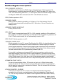
1
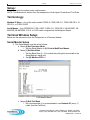
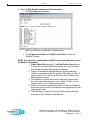
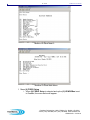
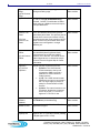
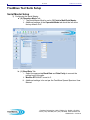
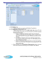
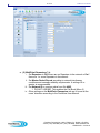
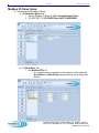
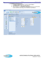
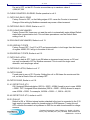
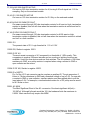
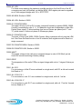
1 of 50
Modbus IO User Manual
Modbus IO
User Manual
Version 2.0, Revision A
IO Slave
(board-level)
IO Slave
(enclosed)
IO Expansion
Radio Base
FGRIO-S
FGR2-IOS-C-U
I2-IOS-C-U
FGR2-IOS-CE-U
FGR2-IO-IOE
FreeWave Technologies, 1880 S. Flatiron Ct., Boulder, CO 80301
Phone: (303) 444-3862, Fax: (303) 786-9948, www.freewave.com
LUM0010AC v. 2.0 Rev A
2 of 50
Modbus IO User Manual
Copyright © 1995-2011 by FreeWave Technologies, Inc. All rights reserved. Published 2011.
W ARRANTY
FREEW AVE TECHNOLOGIES WARRANTS YOUR FREEW AVE® W IRELESS DATA TRANSCEIVER AGAINST DEFECTS IN
MATERIALS AND MANUFACTURING FOR A PERIOD OF TWO YEARS FROM THE DATE OF SHIPMENT. IN THE EVENT OF A
PRODUCT FAILURE DUE TO MATERIALS OR WORKMANSHIP, FREEW AVE WILL, AT ITS OPTION, REPAIR OR REPLACE THE
PRODUCT. THE PRODUCT MUST BE RETURNED TO FREEW AVE UPON RECEIVING A RETURN MATERIAL AUTHORIZATION
(RMA) FOR EVALUATION OF W ARRANTY COVERAGE.
IN NO EVENT WILL FREEW AVE TECHNOLOGIES INC., ITS SUPPLIERS, AND ITS LICENSORS BE LIABLE FOR ANY DAMAGES
ARISING FROM THE USE OF OR INABILITY TO USE THIS PRODUCT. THIS INCLUDES BUSINESS INTERRUPTION, LOSS OF
BUSINESS INFORMATION, OR OTHER LOSS WHICH MAY ARISE FROM THE USE OF THIS PRODUCT. PLEASE BE ADVISED THAT
OEM CUSTOMER’S WARRANTY PERIODS MAY VARY.
W ARRANTY POLICY MAY NOT APPLY:
•
IF PRODUCT REPAIR, ADJUSTMENTS OR PARTS REPLACEMENTS IS REQUIRED DUE TO ACCIDENT, NEGLECT,
UNUSUAL PHYSICAL, ELECTRICAL OR ELECTROMAGNETIC STRESS.
•
IF PRODUCT IS USED OUTSIDE OF FREEW AVE SPECIFICATIONS.
•
IF PRODUCT HAS BEEN MODIFIED, REPAIRED OR ALTERED BY CUSTOMER UNLESS FREEW AVE SPECIFICALLY
AUTHORIZED SUCH ALTERATIONS IN EACH INSTANCE IN WRITING. THIS INCLUDES THE ADDITION OF CONFORMAL
COATING.
SPECIAL RATE REPLACEMENT OPTION
A SPECIAL RATE REPLACEMENT OPTION IS OFFERED TO NON-WARRANTY RETURNS OR UPGRADES. THE OPTION TO
PURCHASE THE REPLACEMENT UNIT AT THIS SPECIAL RATE IS ONLY VALID FOR THAT RMA. THE SPECIAL REPLACEMENT
RATE OPTION EXPIRES IF NOT EXERCISED WITHIN 30 DAYS OF FINAL DISPOSITION OF RMA.
RESTRICTED RIGHTS
ANY PRODUCT NAMES MENTIONED IN THIS MANUAL MAY BE TRADEMARKS OR REGISTERED TRADEMARKS OF THEIR
RESPECTIVE COMPANIES AND ARE HEREBY ACKNOWLEDGED.
INFORMATION IN THIS MANUAL IS SUBJECT TO CHANGE WITHOUT NOTICE AND IS PROPRIETARY AND CONFIDENTIAL TO
FREEW AVE TECHNOLOGIES, INC.
THIS MANUAL IS FOR USE BY PURCHASERS AND OTHER AUTHORIZED USERS OF THE FREEW AVE® W IRELESS DATA
TRANSCEIVER ONLY.
NO PART OF THIS MANUAL MAY BE REPRODUCED OR TRANSMITTED IN ANY FORM OR BY ANY MEANS, ELECTRONIC OR
MECHANICAL, OR FOR ANY PURPOSE WITHOUT THE EXPRESS WRITTEN PERMISSION OF FREEW AVE TECHNOLOGIES, INC.
FREEW AVE’S SPREAD SPECTRUM W IRELESS DATA TRANSCEIVERS ARE DESIGNED AND MANUFACTURED IN THE UNITED
STATES OF AMERICA.
PRINTED IN THE UNITED STATES OF AMERICA.
THIS PRODUCT IS LICENSED BY THE UNITED STATES. DIVERSION CONTRARY TO U.S. LAW IS PROHIBITED. SHIPMENT OR
RE-EXPORT OF THIS PRODUCT OUTSIDE OF THE UNITED STATES MAY REQUIRE AUTHORIZATION BY THE U.S. BUREAU OF
EXPORT ADMINISTRATION. PLEASE CONTACT FREEW AVE TECHNOLOGIES FOR ASSISTANCE AND FURTHER INFORMATION.
FreeWave Technologies, 1880 S. Flatiron Ct., Boulder, CO 80301
Phone: (303) 444-3862, Fax: (303) 786-9948, www.freewave.com
LUM0010AC v. 2.0 Rev A
3 of 50
Modbus IO User Manual
UL Notification:
Models FGR2-IOS-C-U, FGR2-IOS-CE-U, FGR2-IO-IOE, and I2-IOS-C-U are suitable for use
in Class I, Division 2, Groups A, B, C, and D or non-hazardous locations only. Input voltage for
the above models is 6 – 30 V DC
Warning—Explosion Hazard—Substitution of components may impair suitability for Class I,
Division 2.
The diagnostics port and cable do not have a latching connector and cannot be used in a
hazardous location.
Model FGRIO-S is suitable for use in Class I, Division 2, Groups A, B, C, and D or nonhazardous locations only. Input voltage for the above model is 6 – 20 V DC
Warning—Explosion Hazard—Substitution of components may impair suitability for Class I,
Division 2.
The diagnostics port and cable do not have a latching connector and cannot be used in a
hazardous location.
Safety Information:
Do not exceed the maximum ratings for the product.
These products can fail in a variety of modes due to misuse, age, or malfunction. Systems with
these products must be designed to prevent personal injury and property damage during
product operation and in the event of product failure.
The described systems are based on wireless Radio Frequency (RF) technologies. RF is
subject to interference and communication interruptions. It should not be expected, therefore,
to provide 100% communication 100% of the time. The described systems should not be used
without proper provisions to ensure safe operation upon loss of radio communications.
FreeWave Technologies, 1880 S. Flatiron Ct., Boulder, CO 80301
Phone: (303) 444-3862, Fax: (303) 786-9948, www.freewave.com
LUM0010AC v. 2.0 Rev A
4 of 50
Modbus IO User Manual
Table of Contents
Equipment Requirements ............................................................................................................................................................ 5
Decreased Capabilities ............................................................................................................................................................ 5
Setup: .......................................................................................................................................................................................... 6
Terminology: ........................................................................................................................................................................... 6
Terminal Window Setup: ........................................................................................................................................................ 6
Serial Master Setup ............................................................................................................................................................. 6
Modbus IO Slave Setup....................................................................................................................................................... 8
(9) FGRIO Setup Menu Descriptions ............................................................................................................................ 12
FreeWave Tool Suite Setup................................................................................................................................................... 14
Serial Master Setup ........................................................................................................................................................... 14
Modbus IO Slave Setup..................................................................................................................................................... 18
(9) Modbus Settings Tab Descriptions .......................................................................................................................... 21
Modbus Register Map ............................................................................................................................................................... 26
Modbus Register Descriptions .............................................................................................................................................. 30
Installation of the Modbus IO Slave.......................................................................................................................................... 37
(1) Battery or Power Supply.............................................................................................................................................. 37
(2) 1 – 5 Volt Sensor ......................................................................................................................................................... 37
Analog Input 1 or Analog Input 2 ................................................................................................................................. 37
Analog Input 3 or Analog Input 4 ................................................................................................................................. 37
Signal Coupling for Analog Input 3 and Analog Input 4. ............................................................................................. 37
(3) 4-20 Milliamp Sensor .................................................................................................................................................. 39
Analog Input 1 or Analog Input 2 ................................................................................................................................. 39
Analog Input 3 or Analog Input 4 ................................................................................................................................. 39
(4) Digital Input 1 and Digital Input 2............................................................................................................................... 41
(5) Digital Output 1 and Digital Output 2 ......................................................................................................................... 41
Serial Modbus Slave Mode ....................................................................................................................................................... 42
Configuration Instructions for Serial Modbus Slave in Wired Applications ......................................................................... 42
Technical Specifications ........................................................................................................................................................... 44
FGRIO-S Specifications ........................................................................................................................................................ 44
FGR2-IOS-C-U/FGR2-IOS-CE-U Specifications ................................................................................................................ 45
FGR2-IO-IOE Specifications ................................................................................................................................................ 47
I2-IOS-C-U Specifications .................................................................................................................................................... 49
FreeWave Technologies, 1880 S. Flatiron Ct., Boulder, CO 80301
Phone: (303) 444-3862, Fax: (303) 786-9948, www.freewave.com
LUM0010AC v. 2.0 Rev A
5 of 50
Modbus IO User Manual
Equipment Requirements
1. Firmware requirements:
• FGRO9CSU, FGR-115RC, FGR-115WC Serial Master: firmware version 2.44 or
greater
• FGR2-C-U, FGR2-CE-U Serial Master: Any firmware version
• IM-500X007, IM-800X009, IM-900X009: firmware version 3.44 or higher
• I2-C-U, I2-CE: Any firmware version
• FGRIO-S: firmware version 2.64IO or greater
• FGR2-IOS-C-U, FGR2-IOS-CE-U, FGR2-IO-IOE, I2-IOS-C-U: Any firmware version
2. Any FGR, FGR2, IM, or I2 serial radios are to be installed as the Multipoint Master and
Repeater(s) (if required). FGRIO-S, FGR2-IOS-C-U, FGR2-IOS-CE-U, FGR2-IO-IOE,
and I2-IOS-C-U radios are to be installed as a Multipoint Slave.
3. Modbus IO WILL NOT work with DGR series radios.
Decreased Capabilities
Table 1 shows the decreased product capabilities for specific products as of March 18th, 2011:
Product
I2-IOS-C-U
Table 1. Summary of decreased capabilities by product.
Capability
Specification
Analog input accuracy
+/- 0.1%
Actual
+/- 0.5%
FreeWave Technologies, 1880 S. Flatiron Ct., Boulder, CO 80301
Phone: (303) 444-3862, Fax: (303) 786-9948, www.freewave.com
LUM0010AC v. 2.0 Rev A
6 of 50
Modbus IO User Manual
Setup:
The following are the system setup requirements.
NOTE: This document is written from the perspective of both Hyper Terminal and Tool Suite.
Terminology:
Modbus IO Slave – Any of the radio models FGRIO-S, FGR2-IOS-C-U, FGR2-IOS-CE-U, I2IOS-C-U, or FGR2-IO-IOE
Serial Master – Any FGRO9CSU, FGR-115RC, FGR2-C-U, FGR2-CE-U, IM-500X007, IM800X009, IM-900X009, I2-C-U, or I2-CE radio configured as the Multipoint Master.
Terminal Window Setup:
Below are the instructions from the Perspective of a Terminal window:
Serial Master Setup
1) The Serial Master must be set as follows:
a. Menu (0) Set Operation Mode
i. Set the Serial Master to (2) Point to MultiPoint Master.
b. Menu (1) Set Baud Rate
i. Set the Baud Rate (0 – 9) to match the polling host connected to the
Serial Master’s serial port.
ii. Set (B) Modbus RTU to 1
FGR Master Menu 1
c. Menu (2) Edit Call Book
i. Not recommended. It is recommended to use Network ID (see p. 7)
rather than the Call Book.
FreeWave Technologies, 1880 S. Flatiron Ct., Boulder, CO 80301
Phone: (303) 444-3862, Fax: (303) 786-9948, www.freewave.com
LUM0010AC v. 2.0 Rev A
7 of 50
Modbus IO User Manual
d. Menu (3) Edit Radio Transmission Characteristics
i. Set (0) FreqKey as necessary.
Menu (3) Edit Radio Transmission Characteristics
ii. Set (1) Max Packet Size and (2) Min Packet Size to match the
Modbus IO Slave
NOTE: 2 and 2 are the smallest Max and Min Packet sizes that can be used
for Modbus IO Systems.
1. A Max Packet Size setting of 2 and Min Packet Size setting of
2 is also the recommended packet sizing, as it should handle
most Modbus packets with the best throughput.
2. There is a relationship between packet size and maximum
reliable counting rate of the DI counters. With Max = 2, Min = 2
packet sizes, up to 1000 Hz (at 50% duty cycle, 500uSec per
phase) can be counted.
3. The Modbus IO System will function with larger packet sizes,
but count rate will be reduced; sizes of Max = 9, Min = 9 will
reliably count to 10 Hz (50msec per phase).
4. Modbus IO Systems using packet sizes of 2 and 2 will typically
draw more current than if the systems were programmed to use
larger packet sizes.
5. Other settings in menu 3 are to be set at the users’ discretion
according to the FreeWave User Manual.
FreeWave Technologies, 1880 S. Flatiron Ct., Boulder, CO 80301
Phone: (303) 444-3862, Fax: (303) 786-9948, www.freewave.com
LUM0010AC v. 2.0 Rev A
8 of 50
Modbus IO User Manual
FGR Master Menu 5
e. Menu (5) Edit Multipoint Parameters
i. Set (0) Number Repeaters to 0 if there are no Repeaters in the
network or 1 if there are 1 or more Repeaters in the network.
ii. Set (1) Master Packet Repeat according to network interference
conditions and message reliability requirements. A setting of 2 or
greater is recommended.
iii. Set (6) Network ID to a unique value from 0 to 4095. (Do not use 255,
since using this number would enable the CallBook [Menu 2]).
iv. Other settings in menu 5 are to be set at the users’ discretion
according to the FreeWave User Manual.
Modbus IO Slave Setup
2) The Modbus IO Slave must be set as follows:
a. Menu (0) Set Operation Mode – set the Modbus IO Slave to (3) Point to
MultiPoint Slave.
i. DO NOT SET TO (E) FGRIO SLAVE
FreeWave Technologies, 1880 S. Flatiron Ct., Boulder, CO 80301
Phone: (303) 444-3862, Fax: (303) 786-9948, www.freewave.com
LUM0010AC v. 2.0 Rev A
9 of 50
Modbus IO User Manual
Modbus IO Slave Menu 0
b. Menu (1) Set Baud Rate
i. Set (B) Modbus RTU to 1.
ii. If a serial device will be connected to the Modbus IO Slave’s serial
port, the radio’s baud rate (Options 0 – 9) should match the baud rate
of the connected device.
Modbus IO Slave Menu 1
c. Menu (2) Edit Call Book
i. Not recommended. It is recommended to use Network ID (see p.8)
rather than the Call Book.
FreeWave Technologies, 1880 S. Flatiron Ct., Boulder, CO 80301
Phone: (303) 444-3862, Fax: (303) 786-9948, www.freewave.com
LUM0010AC v. 2.0 Rev A
10 of 50
Modbus IO User Manual
d. Menu (3) Edit Radio Transmission Characteristics
i. Set (0) FreqKey as necessary to match the Serial Master or
Repeater.
Modbus IO Slave Menu 3
ii. Set (1) Max Packet Size and (2) Min Packet Size to match the Serial
Master.
iii. Set Retry Time Out; greater than or equal to 64 is recommended.
iv. Other settings in Menu (3) are to be set at the users’ discretion
according to the FreeWave User Manual.
e. Menu (5) Edit Multipoint Parameters
i. Set (1) Master Packet Repeat to match the Modbus Network Master.
ii. Set (6) Network ID to match the Modbus Network Master.
iii. Other settings in menu (5) are to be set at the users’ discretion
according to the FreeWave User Manual.
FreeWave Technologies, 1880 S. Flatiron Ct., Boulder, CO 80301
Phone: (303) 444-3862, Fax: (303) 786-9948, www.freewave.com
LUM0010AC v. 2.0 Rev A
11 of 50
Modbus IO User Manual
Modbus IO Slave Menu 5
Modbus IO Slave Main Menu
f. Menu (9) FGRIO Setup
i. When (9) FGRIO Setup is selected and option (5) IO MODBus is set
to Enabled, the menu below will appear.
FreeWave Technologies, 1880 S. Flatiron Ct., Boulder, CO 80301
Phone: (303) 444-3862, Fax: (303) 786-9948, www.freewave.com
LUM0010AC v. 2.0 Rev A
12 of 50
Modbus IO User Manual
Modbus IO Slave (Board level) Menu 9
Option
(9) FGRIO Setup Menu Descriptions
Function Description
Available
in Models
(0) Default
Delay
This setting configures the time the radio will wait,
after a loss of communication with the Serial Master
or Repeater, before the radio enters default
condition. This value is in .28 second intervals. e.g.
A value of 36 = 36*0.28 sec. = 10.08 sec.
(1)
Not Used
(2)
Not Used
(3) Digital Def1
(4) Digital Def2
Controls the state of the digital output defaults
invoked on loss of communication. See option (0)
Default Delay, described above, for timing.
(0) On - energized (Contact to GND is closed)
(1) Off - not energized (Contact is open)
(2) Unchanged - if communication is lost, do not
change state.
All Modbus IO
Slave models
(5) IO MODBus
Will show IO Modbus as either Enabled or
Disabled. Press 5 to toggle the function. The
screen shot above shows the menu with Modbus
enabled.
Toggles the state of the Sensor Power pin on
power-up.
On - Connected to source voltage
Off - Open Contact
All Modbus IO
Slave models
(6) Sensor
Power Default
All Modbus IO
Slave models
All Modbus IO
Slave models
FreeWave Technologies, 1880 S. Flatiron Ct., Boulder, CO 80301
Phone: (303) 444-3862, Fax: (303) 786-9948, www.freewave.com
LUM0010AC v. 2.0 Rev A
13 of 50
(7) DI1 Counter
Edge
(8) DI2 Counter
Edge
(9) ModBus ID
Modbus IO User Manual
DI1 and DI2 Counter Edge, toggles between
Rising and Falling edge.
All Modbus IO
Slave models
Modbus ID is a user -selectable value from
1– 246, or, with (G) 16 Bit Addressing
Enabled, 1-65535. Each Modbus IO Slave
radio acting as a Modbus device will require
a unique Modbus ID.
All Modbus IO
Slave models
Clear Counter (1 or 2) on Read, if set to
‘Yes’, will clear the count on the given DI
immediately after Read. This prevents loss of
counts which could occur between a Read
operation and a later Clear operation. NOTE:
Clear on Read only works when both 16 bit
registers are read together in a single
Modbus poll.
All Modbus IO
Slave models
User-entered values to subtract from the AI1
and AI2 MSW (Most Significant Word)
measurements to provide zero-shifted
versions of AI1 and AI2. The results can be
either clipped at zero or allowed to wrap to
full scale. See the Register Map for further
information.
Controls the power-up states of the internal
resistor (10 KΩ) connected to the DIs.
• (0) Down: The 10 KΩ internal
resistor attached to the input is
connected to GND to provide a
pulldown for closed-contact-tovoltage sensors.
• (1) Up: The 10 KΩ internal resistor
attached to the input is connected to
the 3.3V logic supply to provide a
pullup for closed-contact-to-GND
sensors.
• (2) None: The internal resistor is not
connected, allowing the connected
sensor to provide > 1.75V DC for
high and <1.75V DC for low.
All Modbus IO
Slave models
(G) 16 Bit
Modbus
Address
(H) Local
Modbus Parse
Toggles between Disabled (8-bit addressing)
and Enabled (16-bit addressing)
All Modbus IO
Slave models
This option is used for FreeWave Tool Suite
Application Support
All Modbus IO
Slave models
AI(DI1) and
AI(DI2)Filter
Toggles between filtered (reading an analog
signal on DI1 or 2) and Non Filtered (reading
a Digital signal on DI1 or DI2).
(A) Clear
Counter 1 on
Read
(B) Clear
Counter 2 on
Read
(C) AI1 Custom
Offset
(D) AI2 Custom
Offset
(E) DI1 Pull
Up/Down
(F) DI2 Pull
Up/Down
All Modbus IO
Slave models
FreeWave Technologies, 1880 S. Flatiron Ct., Boulder, CO 80301
Phone: (303) 444-3862, Fax: (303) 786-9948, www.freewave.com
LUM0010AC v. 2.0 Rev A
14 of 50
Modbus IO User Manual
FreeWave Tool Suite Setup
Serial Master Setup
3) Configuring the Serial Master:
a. (0) Operation Mode Tab
i. The Serial Master Must be set to (2) Point to MultiPoint Master.
ii. Additional settings of the Operation Mode tab should be left at the
factory default of off.
b. (1) Baud Rate Tab
i. Select the appropriate Baud Rate and Data Parity to connect the
polling host to the radio.
ii. Modbus RTU MUST be set to 1.
iii. Additional settings to be set per the FreeWave Spread Spectrum User
Manual.
FreeWave Technologies, 1880 S. Flatiron Ct., Boulder, CO 80301
Phone: (303) 444-3862, Fax: (303) 786-9948, www.freewave.com
LUM0010AC v. 2.0 Rev A
15 of 50
Modbus IO User Manual
c. (2) Call Book Tab
i. The call book tab is not used in the Modbus IO application.
d. (3) Transmission Characteristics Tab
i. A Max Packet size setting of 2 and Min Packet size setting of 2 is the
recommended packet sizing, as it should handle most Modbus packets
with the best throughput.
1. There is a relationship between packet size and maximum
reliable counting rate of the DI counters. With 2, 2 packet sizes,
up to 1000 Hz (at 50% duty cycle, 500uSec per phase) can be
counted.
2. The Modbus IO System will function with larger packet sizes,
but count rate will be reduced; sizes of 9, 9 will reliably count to
10 Hz (50msec per phase).
3. Modbus IO Systems using packet sizes of 2 and 2 will typically
draw more current than if the systems were programmed to use
larger packet sizes.
ii. Other settings on the Transmission Characteristics tab are to be set
at the users’ discretion according to the FreeWave User Manual.
FreeWave Technologies, 1880 S. Flatiron Ct., Boulder, CO 80301
Phone: (303) 444-3862, Fax: (303) 786-9948, www.freewave.com
LUM0010AC v. 2.0 Rev A
16 of 50
Modbus IO User Manual
e. (5) MultiPoint Parameters Tab
i. Set Repeaters to Off if there are no Repeaters in the network or On if
there are 1 or more Repeaters in the network.
ii. Set Master Packet Repeat according to network interference
conditions and message reliability requirements. A setting of 2 or
greater is recommended.
iii. Set Network ID to a unique value from 0 to 4095.
1. DO NOT USE 255. This enables the Call Book (Menu 2)
iv. Other settings on the MultiPoint Parameters tab are to be set at the
users’ discretion according to the FreeWave User Manual.
FreeWave Technologies, 1880 S. Flatiron Ct., Boulder, CO 80301
Phone: (303) 444-3862, Fax: (303) 786-9948, www.freewave.com
LUM0010AC v. 2.0 Rev A
17 of 50
Modbus IO User Manual
FreeWave Technologies, 1880 S. Flatiron Ct., Boulder, CO 80301
Phone: (303) 444-3862, Fax: (303) 786-9948, www.freewave.com
LUM0010AC v. 2.0 Rev A
18 of 50
Modbus IO User Manual
Modbus IO Slave Setup
4) Configuring the Modbus IO Slave:
a. (0) Operation Mode Tab
i. Set the Modbus IO Slave to (3) Point to Multipoint Slave.
ii. DO NOT SET TO (E) FGRIO Slave (NOT IO-MODBUS)
b. (1) Baud Rate Tab
i. Set Modbus RTU to 1
1. If a serial device is connected to the data port of the radio the
Baud Rate and Data Parity settings must be set to match the
device.
FreeWave Technologies, 1880 S. Flatiron Ct., Boulder, CO 80301
Phone: (303) 444-3862, Fax: (303) 786-9948, www.freewave.com
LUM0010AC v. 2.0 Rev A
19 of 50
Modbus IO User Manual
c. (2) Call Book Tab
i. Not applicable - The Call book tab is not used in a Modbus IO system.
d. (3) Transmission Characteristics Tab
i. Set Frequency Key as necessary to match the Serial Master or
Repeater.
ii. Set Max Packet Size and Min Packet Size to match the Serial Master.
iii. Set Retry Timeout, >= 64 is recommended.
iv. Other settings on the Transmission Characteristics tab are to be set
at the users’ discretion according to the FreeWave User Manual.
FreeWave Technologies, 1880 S. Flatiron Ct., Boulder, CO 80301
Phone: (303) 444-3862, Fax: (303) 786-9948, www.freewave.com
LUM0010AC v. 2.0 Rev A
20 of 50
Modbus IO User Manual
e. (5) MultiPoint Parameters tab
i. Set Master Packet Repeat to match the Serial Master.
ii. Set Network ID to match the Serial Master.
iii. Other settings on the MultiPoint Parameters tab are to be set at the
users’ discretion according to the FreeWave User Manual.
FreeWave Technologies, 1880 S. Flatiron Ct., Boulder, CO 80301
Phone: (303) 444-3862, Fax: (303) 786-9948, www.freewave.com
LUM0010AC v. 2.0 Rev A
21 of 50
Modbus IO User Manual
5) (9) Modbus Settings Tab
(9) Modbus Settings Tab Descriptions
Option
Function Description
Modbus Mode
For a radio to operate as a Modbus IO Slave, this option
must be Enabled. If set to Disabled, the radio will not
respond to Modbus polls.
Modbus
Address Size
Modbus ID
Set the radio for 8 bit or 16 bit Modbus addressing
Sensor Power
Default
AI1 250 Ohms
Modbus ID is a user -selectable value from 1– 246 with
Modbus Address Size set to 8 bit. With Modbus
Address Size set to 16 bit the value is 1-65535. Each
Modbus IO Slave acting as a Modbus device will require
a unique Modbus ID.
Disabled: Upon power up, before any Modbus
commands modifying Sensor Power have been
received, the Sensor Power pin will have no voltage
applied to it.
Enabled: Upon power up, before any Modbus
commands modifying Sensor Power have been
received, the Sensor Power pin will provide voltage
equal to the supply voltage of the radio.
Places a termination resistor in parallel with the AI1
terminal, converting a 4 – 20 mA signal applied to AI1
into a 1 – 5 V signal.
Available in
Models
All Modbus IO
Slaves
All Modbus IO
Slaves
All Modbus IO
Slaves
All Modbus IO
Slaves
FGR2-IOS-CE-U
ONLY
FreeWave Technologies, 1880 S. Flatiron Ct., Boulder, CO 80301
Phone: (303) 444-3862, Fax: (303) 786-9948, www.freewave.com
LUM0010AC v. 2.0 Rev A
22 of 50
Modbus IO User Manual
AI1 User Offset
User-entered value that is subtracted from the AI1 MSW
(Most Significant Word) value. The result is provided in
the AI1 MSW Offset Result Register value.
All Modbus IO
Slaves
Clip AI1 Offset
At Zero
Disabled: If the value of AI1 User Offset is greater than
the value of AI1 MSW, the value of AI1 MSW Offset
Result will “wrap around” to the top of the scale. For
Example: AI1 User Offset = 10000 and AI1 MSW =
5000. The value of AI1 MSW Offset Result would be
60535.
All Modbus IO
Slaves
AI2 250 Ohms
AI2 User Offset
Clip AI2 Offset
At Zero
Fast AI (DI 1)
Enabled: If the value of AI1 User Offset is greater than
the value of AI1 MSW, the value of AI1 MSW Offset
Result will be “clipped” at 0 and will not “wrap around” to
the top of the scale. For Example: AI1 User Offset =
10000 and AI1 MSW = 5000. The value of AI1 MSW
Offset Result would be 0.
Places a termination resistor in parallel with the AI2
terminal, converting a 4 – 20 mA signal applied to AI2
into a 1 – 5 V signal.
User-entered value that is subtracted from the AI2 MSW
(Most Significant Word) value. The result is provided in
the AI2 MSW Offset Result Register value.
Disabled: If the value of AI2 User Offset is greater than
the value of AI2 MSW, the value of AI2 MSW Offset
Result will “wrap around” to the top of the scale.
Example: AI2 User Offset = 10000 and AI2 MSW =
5000. The value of AI2 MSW Offset Result would be
60535.
Enabled: If the value of AI2 User Offset is greater than
the value of AI2 MSW, the value of AI2 MSW Offset
Result will be “clipped” at 0 and will not “wrap around” to
the top of the scale. Example: AI2 User Offset = 10000
and AI2 MSW = 5000. The value of AI2 MSW Offset
Result would be 0.
Filtered: The value reported is an ongoing average of
the voltage received by the radio.
Fast AI (DI 2)
FGR2-IOS-CE-U
ONLY
All Modbus IO
Slaves
All Modbus IO
Slaves
All models
EXCEPT
FGRIO-S
Fast: The value reported is the last sample value of the
voltage received by the radio.
Counting Mode
Fast: The currently sampled voltage is directly
compared to the previous value to determine if the
Counter should be incremented.
All models
EXCEPT
FGRIO-S
Debounced: The voltage is observed over 2 – 3
consecutive samples. Only if all of the sampled values
are different from the previous Counter state will the
Counter increment.
Filtered: The currently sampled voltage is compared to
an ongoing average of values. If the sampled value is
different from the ongoing average, the Counter will be
incremented.
FreeWave Technologies, 1880 S. Flatiron Ct., Boulder, CO 80301
Phone: (303) 444-3862, Fax: (303) 786-9948, www.freewave.com
LUM0010AC v. 2.0 Rev A
23 of 50
DI1 125 Ohms
DI1 Pullup
DI1 Counter
Edge
Clear Cntr 1 On
Read
Modbus IO User Manual
Places a termination resistor in parallel with the DI1
terminal, converting a 4 – 20 mA signal applied to DI1
into a 0.5 – 2.5 V signal. This should be used if
connecting a 4 – 20 mA signal to read AI of DI1.
Controls the power-up states of the internal resistor (10
KΩ) connected to DI1.
• (0) Down: The 10 KΩ internal resistor attached
to the input is connected to GND to provide a
pulldown for closed-contact-to-voltage sensors.
• (1) Up: The 10 KΩ internal resistor attached to
the input is connected to the 3.3V logic supply to
provide a pullup for closed-contact-to-GND
sensors.
• (2) None: The internal resistor is not connected,
allowing the connected sensor to provide >
1.75V DC for high and <1.75V DC for low.
Determines whether the Counter for DI1 will increment
on the Falling edge or the Raising edge of the voltage
reading.
FGR2-IOS-CE-U
ONLY
Disabled: DI1 Counter MSW and DI1 Counter LSW
will not be automatically cleared.
FGRIO-S, FGR2IOS, and I2-IOS
All Modbus IO
Slaves
All Modbus IO
Slaves
Enabled: The values in DI1 Counter MSW and DI1
Counter LSW are cleared immediately after a Modbus
Read command is executed.This can prevent loss of
counts which could occur between a Read operation and
a later Clear operation.
NOTE: Clear Cntr 1 On Read only works when both 16
bit registers (DI1 Counter MSW and DI1 Counter LSW)
are read together in a single Modbus poll.
DI2 125 Ohms
DI2 Pullup
DI2 Counter
Edge
Clear Cntr 2 On
Read
Places a termination resistor in parallel with the DI2
terminal, converting a 4 – 20 mA signal applied to DI2
into a 0.5 – 2.5 V signal. This should be used if
connecting a 4 – 20 mA signal to read AI of DI2.
Controls the power-up states of the internal resistor (10
KΩ) connected to DI2.
• (0) Down: The 10 KΩ internal resistor attached
to the input is connected to GND to provide a
pulldown for closed-contact-to-voltage sensors.
• (1) Up: The 10 KΩ internal resistor attached to
the input is connected to the 3.3V logic supply to
provide a pullup for closed-contact-to-GND
sensors.
• (2) None: The internal resistor is not connected,
allowing the connected sensor to provide >
1.75V DC for high and <1.75V DC for low.
Determines whether the Counter for DI2 will increment
on the Falling edge or the Raising edge of the voltage
reading.
Disabled: DI2 Counter MSW and DI2 Counter LSW
will not be automatically cleared.
FGR2-IOS-CE-U
ONLY
All Modbus IO
Slaves
All Modbus IO
Slaves
Enabled: The values in DI2 Counter MSW and DI2
Counter LSW are cleared immediately after a Modbus
Read command is executed.This can prevent loss of
counts which could occur between a Read operation and
FreeWave Technologies, 1880 S. Flatiron Ct., Boulder, CO 80301
Phone: (303) 444-3862, Fax: (303) 786-9948, www.freewave.com
LUM0010AC v. 2.0 Rev A
24 of 50
Modbus IO User Manual
a later Clear operation.
DO Bi-Stable
DO Monostable
Time
NOTE: Clear Cntr 2 On Read only works when both 16
bit registers (DI2 Counter MSW and DI2 Counter LSW)
are read together in a single Modbus poll.
Constant: The DO operates as a bi-stable digitale
output. The DO will remain on as long as the coil (DO1
or DO2, see p. 26) is set to 1. The coil will not be
automatically set to 0.
Auto-Off: The DO will remain on for the duration set in
DO Monostable Time (see below) or until the
appropriate coil (DO1 or DO2, see p. 26) is set to 0,
whichever is shorter. After the DO Monostable Time
has elapsed, the appropriate coil will be set to 0 (Off).
The DO will remain off until a 1 is once again written to
the appropriate coil.
Sets the length of time a DO will remain on when DO BiStable is set to Auto-Off (see above). The amount of
time is in 150 millisecond increments. The setting can
range from 0 (see note) to 255 (approx. 28.25 seconds).
All Modbus IO
Slaves
All Modbus IO
Slaves
NOTE: A setting of 0 will cause the DO to turn off at an
unspecified amount of time. This time will always be less
than 150 milliseconds, but the actual time may vary.
Digital Out 1
Default
Digital Out 2
Default
AO1 Custom
Offset
AO1
Unchanged
Controls the state of the digital output defaults invoked
on loss of communication. See Default Delay (below)
for timing.
Output ON: Energized (Contact to GND is closed)
Output OFF: Not energized (Contact is open)
No Change: If communication is lost, do not change
state.
User-entered value that is added to the AO1 Command
value. The resulting total is the value reported when
reading the AO1 Command register value.
Controls the state of AO1 invoked on loss of
communication. See Default Delay (below) for timing.
All Modbus IO
Slaves
All models
EXCEPT
FGRIO-S
All models
EXCEPT
FGRIO-S
Disabled: If communication is lost, AO1 Command will
be set to the value in AO1 Default Cmd.
AO1 Default
Cmd
AO2 Custom
Offset
AO2
Unchanged
Enabled: If communication is lost, AO1 Command will
remain set at the last written value.
Upon loss of communication, if the AO1 Unchanged
setting is set to Disabled (see above), AO1 Command
will be set to this value.
User-entered value that is added to the AO2 Command
value. The resulting total is the value reported when
reading the AO2 Command register value.
Controls the state of AO2 invoked on loss of
communication. See Default Delay (below) for timing.
All models
EXCEPT
FGRIO-S
All models
EXCEPT
FGRIO-S
All models
EXCEPT
FGRIO-S
Disabled: If communication is lost, AO2 Command will
be set to the value in AO2 Default Cmd (see p. 25).
Enabled: If communication is lost, AO1 Command will
remain set at the last written value.
FreeWave Technologies, 1880 S. Flatiron Ct., Boulder, CO 80301
Phone: (303) 444-3862, Fax: (303) 786-9948, www.freewave.com
LUM0010AC v. 2.0 Rev A
25 of 50
AO2 Default
Cmd
Default Delay
Upon loss of communication, if the AO2 Unchanged
setting is set to Disabled (see p. 24), AO1 Command
will be set to this value.
This setting configures the time the radio will wait, after a
loss of communication with the Serial Master or
Repeater, before the radio enters default condition. This
value is in .28 second intervals. e.g. A value of 36 =
36*0.28 sec. = 10.08 sec.
Modbus IO User Manual
All models
EXCEPT
FGRIO-S
All Modbus IO
Models
FreeWave Technologies, 1880 S. Flatiron Ct., Boulder, CO 80301
Phone: (303) 444-3862, Fax: (303) 786-9948, www.freewave.com
LUM0010AC v. 2.0 Rev A
26 of 50
Modbus IO User Manual
Modbus Register Map
REGISTER MAP FOR MODBUS IO SLAVES
Read Only,
RO
Read/Write, RW
TYPE
ADDRESS
COLOR KEY
Non-Volatile on PWR cycle,
10,000-write lifetime limit
ENTITY
New Feature
BITS
PROTOCOL PLC
Coils, read with command code 01.
NOTES
All addresses described are "PLC"
numbers
"COIL"
0
1
DO1
1
"COIL"
1
2
DO2
1
"COIL"
"COIL"
"COIL"
"COIL"
"COIL"
2
3
4
5
6
3
4
5
6
7
1
1
1
1
1
"COIL"
"COIL"
"COIL"
7
8
9
8
9
10
1
1
1
DOx have defaulted, clear by user
Default OFF
Default OFF
"COIL"
10
11
1
Default OFF; Increment on 1-0 Edge
"COIL"
11
12
1
Default OFF; Increment on 1-0 Edge
"COIL"
12
13
1
Default ON, Overrides DO1 Default
"COIL"
"COIL"
"COIL"
"COIL"
"COIL"
"COIL"
"COIL"
"COIL"
"COIL"
"COIL"
13
14
15
16
17
18
19
20
21
22
14
15
16
17
18
19
20
21
22
23
SENSOR PWR
SENSOR DEFAULT
DO1 FAULT
DO2 FAULT
SENSOR PWR FAULT
COMM FAIL FAULT
LATCH
CLR CNTR1 ON RD
CLR CNTR2 ON RD
CNTR1 INC ON 0-1
EDGE
CNTR2 INC ON 0-1
EDGE
DO1 LEAVE
UNCHANGED
DO2 LEAVE
UNCHANGED
DO1 DEFAULT STATE
DO2 DEFAULT STATE
CNTR1 INC LATCH
CNTR2 INC LATCH
CNTR1 CLEAR
CNTR2 CLEAR
AI1 OFFSET CLIP AT 0
AI2 OFFSET CLIP AT 0
Reserved
On Read, returns actual state if ~=
Command; Power-up Default = OFF
On Read, returns actual state if ~=
Command; Power-up Default = OFF
On Read, returns actual state if ~=
Command
Default = OFF
Auto-Clears fault if successful retry
Auto-Clears fault if successful retry
Auto-Clears fault if successful retry
1
1
1
1
1
1
1
1
1
1
Default ON, Overrides DO2 Default
Default OFF
Default OFF
ON at inc; OFF by user
ON at inc; OFF by user
Default OFF, pulsed so Read = always OFF
Default OFF, pulsed so Read = always OFF
Default ON
Default ON
"COIL"
"COIL"
"COIL"
"COIL"
23
24
25
26
24
25
26
27
1
1
1
1
"COIL"
27
28
"COIL"
28
29
Ignore Broadcasts
DI1 PULLUP
DI2 PULLUP
DO's BI-STABLE
AO1/VSNS LEAVE
UNCHANGED
AO2 LEAVE
UNCHANGED
1
1
Turn OFF to obey broadcasts (ID=0),
defaults ON
Default ON, OFF = PULLDOWN
Default ON, OFF = PULLDOWN
Default ON, OFF = Monostable (1-shot)
Default ON, Overrides AO1/VSNS Default
Cmd
Default ON, Overrides AO2 Default
Command
FreeWave Technologies, 1880 S. Flatiron Ct., Boulder, CO 80301
Phone: (303) 444-3862, Fax: (303) 786-9948, www.freewave.com
LUM0010AC v. 2.0 Rev A
27 of 50
Modbus IO User Manual
"COIL"
"COIL"
"COIL"
29
30
31
30
31
32
DEBOUNCE
COUNTERS IN
FILTER COUNTERS IN
RESET RADIO
1
1
1
"COIL"
32
33
FAST AI(DI1)
1
"COIL"
"COIL"
"COIL"
33
34
35
34
35
36
FAST AI(DI2)
DI1 PULLUP ACTIVE
DI2 PULLUP ACTIVE
AI1 250 OHM PD
"COIL"
36
37 ACTIVE
AI2 250 OHM PD
"COIL"
37
38 ACTIVE
DI1 125 OHM PD
"COIL"
38
39 ACTIVE
DI2 125 OHM PD
"COIL"
39
40 ACTIVE
"COIL"
40
41 Reserved
"COIL"
41
42 Reserved
"COIL"
42
43 Reserved
"COIL"
43
44 Reserved
AI1 250 OHM PD
"COIL"
44
45 FAULT
AI2 250 OHM PD
"COIL"
45
46 FAULT
DI1 125 OHM PD
"COIL"
46
47 FAULT
DI2 125 OHM PD
"COIL"
47
48 FAULT
Discrete Inputs, read with command code 02.
DISCRETE IN
10000 10001 DI1
DISCRETE IN
10001 10002 DI2
DISCRETE IN
10002 10003 DI of AI1
DISCRETE IN
10003 10004 DI of AI2
DISCRETE IN
10004 10005 DTR
1
1
1
Default ON; OFF for High Speed Counting
Default ON; OFF for High Speed Counting
Always Reads OFF; Write ON for Reset
Default ON = Samples, OFF=Filtered
Average
Default ON = Samples, OFF=Filtered
Average
Default ON; OFF Overrides DI1PULLUP
Default ON; OFF Overrides DI2PULLUP
1
Default OFF, Enclosure Model Only
1
Default OFF, Enclosure Model Only
1
Default OFF, Enclosure Model Only
1
1
1
1
1
Default OFF, Enclosure Model Only
1
Enc. Model Only; Auto-Clears if succ. retry
1
Enc. Model Only; Auto-Clears if succ. retry
1
Enc. Model Only; Auto-Clears if succ. retry
1
Enc. Model Only; Auto-Clears if succ. retry
1
1
1
1
1
Real-Time state of DI1; "1" = DI1 > 1.75V
Real-Time state of DI2; "1" = DI2 > 1.75V
Compare of AI1: "1" = AI1 > 1.65V
Compare of AI2: "1" = AI2 > 1.65V
Real-Time state of IODTR line on J3
FreeWave Technologies, 1880 S. Flatiron Ct., Boulder, CO 80301
Phone: (303) 444-3862, Fax: (303) 786-9948, www.freewave.com
LUM0010AC v. 2.0 Rev A
28 of 50
Input Registers, read with command code 04.
INPUT REG
30000
30001 AI1 MSW
INPUT REG
30001
30002 A1 LSW
INPUT REG
30002
30003 AI2 MSW
INPUT REG
30003
30004 A2 LSW
INPUT REG
30004
30005 DI1 COUNTER MSW
INPUT REG
30005
30006 DI1 COUNTER LSW
INPUT REG
30006
30007 DI2 COUNTER MSW
INPUT REG
30007
30008 DI2 COUNTER LSW
INPUT REG
30008
30009 Vbatt
INPUT REG
30009
30010 degC
INPUT REG
30010
30011 ALL DI'S
INPUT REG
30011
30012 ALL COILS 16:1
INPUT REG
30012
30013 ALL COILS 32:17
INPUT REG
30013
30014 AI1 MSW Offset Result
INPUT REG
30014
30015 AI2 MSW Offset Result
INPUT REG
30015
30016 AI(DI1)
INPUT REG
30016
30017 AI(DI2)
INPUT REG
30017
30018 AI1
INPUT REG
30019
30020 AI2
INPUT REG
30021
30022 AI(DI1)
INPUT REG
30023
30024 AI(DI2)
INPUT REG
30025
30026 Vbatt
INPUT REG
30027
30028 degC
Modbus IO User Manual
16
16
16
16
16
16
16
16
16
16
16
16
16
16
16
16
16
32FP
32FP
32FP
32FP
32FP
32FP
INPUT REG
30029
30030
DO1 CURRENT
16
INPUT REG
INPUT REG
INPUT REG
INPUT REG
INPUT REG
INPUT REG
INPUT REG
30030
30031
30032
30033
30034
30035
30036
30031
30032
30033
30034
30035
30036
30037
DO2 CURRENT
Reserved1
Reserved2
ALL COILS 48:33
Reserved
Reserved
Reserved
16
16
16
16
INPUT REG
INPUT REG
INPUT REG
INPUT REG
INPUT REG
INPUT REG
30037
30038
30039
30040
30041
30042
30038
30039
30040
30041
30042
30043
Discrete In 16:1
Reserved
Reserved
Reserved
Reserved
Reserved
16
Upper 16 bits; msb=5V, lsb=152.587uV
Lower bits, lsb=2.3283nV
Upper 16 bits; msb=5V, lsb=152.587uV
Lower bits, lsb=2.3283nV
Upper 16 bits of 32 bit counter
Lower 16 bits of 32 bit counter
Upper 16 bits of 32 bit counter
Lower 16 bits of 32 bit counter
Supply Voltage; 0-33.164V, lsb=32.62mV
Signed degC temperature of radio PCB
10016:10001, unused bits = 0's
PLC Addresses 16:1, but Read-Only
PLC Addresses 32:17, but Read-Only
AI1 MSW - AI1 USER OFFSET
AI2 MSW - AI2 USER OFFSET
0-3.5Vin; lsb=53.406uV
0-3.5Vin; lsb=53.406uV
IEEE754 Short Float in unscaled Volts
IEEE754 Short Float in unscaled Volts
IEEE754 Short Float in unscaled Volts
IEEE754 Short Float in unscaled Volts
IEEE754 Short Float in unscaled Volts
IEEE754 Short Float in unscaled Celsius
lsb=534uA, Res=34mA; Not Accurate in
Fault
lsb=534uA, Res=34mA; Not Accurate in
Fault
PLC Addresses 48:33, but Read-Only
reserved for Coils 64:49
reserved for Coils 80:65
reserved for Coils 96:81
PLC Addrs 16:1, Read-Only, MSB=16,
LSB=1
reserved for Discrete In 32:17
reserved for Discrete In 48:33
reserved for Discrete In 64:49
reserved for Discrete In 80:65
reserved for Discrete In 96:81
FreeWave Technologies, 1880 S. Flatiron Ct., Boulder, CO 80301
Phone: (303) 444-3862, Fax: (303) 786-9948, www.freewave.com
LUM0010AC v. 2.0 Rev A
29 of 50
Modbus IO User Manual
Holding Registers, read with command code 03.
HOLDING REG 40000 40001 ALL COILS 16:1
HOLDING REG 40001 40002 ALL COILS 32:17
16
16
HOLDING REG
HOLDING REG
HOLDING REG
40002
40003
40004
40003
40004
40005
DO's DEFAULT DELAY
AI1 USER OFFSET
AI2 USER OFFSET
16
16
16
HOLDING REG
HOLDING REG
HOLDING REG
HOLDING REG
HOLDING REG
HOLDING REG
HOLDING REG
HOLDING REG
HOLDING REG
HOLDING REG
HOLDING REG
HOLDING REG
HOLDING REG
HOLDING REG
HOLDING REG
40005
40006
40007
40008
40009
40010
40011
40006
40007
40008
40009
40010
40011
40012
16
16
16
16
16
16
16
40033
40034
40035
40036
40034
40035
40036
40037
DO MONOSTABLE TIME
AO1 Command
AO2 Command
AO1/VSNS Default Cmd
AO2 Default Command
AO1 Customer Offset
AO2 Customer Offset
Reserved
Reserved
Reserved
Reserved
ALL COILS 48:33
Reserved
Reserved
Reserved
HOLDING REG
HOLDING REG
HOLDING REG
HOLDING REG
HOLDING REG
HOLDING REG
40037
40038
40039
40040
40041
40042
40038
40039
40040
40041
40042
40043
Discrete In 16:1
Reserved
Reserved
Reserved
Reserved
Reserved
16
HOLDING REG
HOLDING REG
HOLDING REG
HOLDING REG
HOLDING REG
42000
42001
42002
42003
42004
42001
42002
42003
42004
42005
DI1
DI2
DI of AI1
DI of AI2
DTR
16
1
1
1
1
1
PLC Addresses 16:1
PLC Addresses 32:17
.28 sec units of Retry Timeout to DO
Defaults
Value to subtract from 30001 for 30014
Value to subtract from 30002 for 30015
Duration of DO ON, if 27 OFF,
~.15sec/count, range 0-255
0-22mA: lsb=335.693nA
0-22mA: lsb=335.693nA
0-22mA: lsb=335.693nA
0-22mA: lsb=335.693nA
Added to 40007 lsb=335.693nA
Added to 40008 lsb=335.693nA
PLC Addresses 48:33, but Read-Only
reserved for Coils 64:49
reserved for Coils 80:65
reserved for Coils 96:81
PLC Addrs 16:1, Read-Only, MSB=16,
LSB=1
reserved for Discrete In 32:17
reserved for Discrete In 48:33
reserved for Discrete In 64:49
reserved for Discrete In 80:65
reserved for Discrete In 96:81
Real-Time state of DI1; "1" = DI1 > 1.75V
Real-Time state of DI2; "1" = DI2 > 1.75V
Compare of AI1: "1" = AI1 > 1.65V
Compare of AI2: "1" = AI2 > 1.65V
Real-Time state of IODTR line on J3
Explanatory Notes by PLC Address:
Note: The radio will treat requested register addresses below 00256 as implicitly referencing
higher registers according to the command code issued.
• For example, a command to “Read Holding Register 00003” will return the contents of
register 40003, as the Holding Registers all reside at 40000 and above.
• Similarly, a command to “Read Discrete Input 00002” will return the state of address
10002.
• A request to “Read Coil 00002” will return the state of address 00002, as the coils
actually are resident at addresses below 256.
FreeWave Technologies, 1880 S. Flatiron Ct., Boulder, CO 80301
Phone: (303) 444-3862, Fax: (303) 786-9948, www.freewave.com
LUM0010AC v. 2.0 Rev A
30 of 50
Modbus IO User Manual
Modbus Register Descriptions
1 DO1; DISCRETE OUTPUT #1
Emulates a contact closure to GND using a solid-state device. Rated current is 2.0
Amps maximum; protection algorithms will shut OFF the DO at about 2.25 Amps. See
“coil” 5 for Fault sensing and coils 13, 15 and register 40003 for Default settings. Coil 27
and Register 40006 allow automatic shut OFF of the DO after an interval.
2 DO2; Similar operation to DO1
3 SENSOR POWER
Radio power-on default controlled by coil 4. See coil 7 for Fault sensing. The I/O
terminal is now shared with Analog Output AO1. Activation of this coil overrides any
setting of AO1.
4 SENSOR POWER-ON DEFAULT
Factory Pre-set to ON.
5 DO1 FAULT
DO1 Current is sensed and turned OFF if > 2.25A nominal, resulting in ON condition of
this synthetic “coil”. Radio periodically turns DO1 back ON and checks for persistence of
Fault. If Fault condition ends, this coil automatically reverts to OFF.
6 DO2 FAULT; Similar operation to coil 5.
7 SENSOR POWER FAULT
Similar operation to coils 5, 6, except Fault threshold is >50mA. An algorithm allows the
Fault threshold to be exceeded for several milliseconds to allow charging of external
sensor bypass capacitors. Sensors having large bypass capacitance may nevertheless
force this Fault and not be usable with the Sensor Power output. Such devices may be
low-side switched with a DO or permanently powered by B+ IN.
It is possible to achieve an extra pseudo-DI function by powering a resistor sized to
draw approximately 100mA from Sensor Power connected to a contact closure whose
other side is GND. Closure causes a “1” on Read of this coil. Since the re-try duty cycle
of the 100mA current is low, only about 1mA of extra average supply current results.
Any powered sensors present would need to be powered by direct connection to B+ IN.
8 COMM FAIL FAULT LATCH
In case of communication failure, DO’s can be set up to go to Default states under
control of coils 13-16. This coil serves to inform (after communication is restored) that
the link was lost long enough to activate the Defaults. This coil remains ON until turned
OFF by Modbus command.
9 CLEAR COUNTER 1 ON READ
If ON, this coil causes the DI1 counter to be cleared automatically when Read,
preventing loss of counts occurring between a Read and subsequent Clear (see coil
19). This coil only functions if the Read is of both registers 30005 and 30006. Factory
FreeWave Technologies, 1880 S. Flatiron Ct., Boulder, CO 80301
Phone: (303) 444-3862, Fax: (303) 786-9948, www.freewave.com
LUM0010AC v. 2.0 Rev A
31 of 50
Modbus IO User Manual
Pre-set is OFF, so that DI1 Counter accumulates up to maximum value of
4,294,967,295.
10 CLEAR COUNTER 2 ON READ; Similar operation to coil 9.
11 CNTR1 INC ON 0-1 EDGE
Factory Pre-set is OFF, so that falling edges of DI1 cause the Counter to increment.
Change of this setting by Modbus command may cause a false increment.
12 CNTR2 INC ON 0-1 EDGE; Similar to coil 11.
13 DO1 LEAVE UNCHANGED
Factory Pre-set ON. Users may not want the radio to automatically enter defined Default
states after communication loss. This coil takes precedence over the Default State
setting of coil 15.
14 DO2 LEAVE UNCHANGED; Similar to coil 13.
15 DO1 DEFAULT STATE
Factory Pre-set OFF. If coil 13 is OFF and communication is lost longer than the timeout
of register 40003, DO1 will go to the state of this coil.
16 DO2 DEFAULT STATE; Similar to coil 15.
17 CNTR1 INC LATCH
Power-on state is OFF. Latch is set ON when an increment event occurs on DI1 and
can only be cleared to OFF by Modbus command. This is useful for single event
detection, such as plunger arrival.
18 CNTR2 INC LATCH; Similar to coil 17
19 CNTR1 CLEAR
Forced reset to zero of DI1 Counter. Setting this coil to ON clears the counter and this
coil, so that a Read of this coil is always OFF.
20 CNTR2 CLEAR; Similar to coil 19.
21 AI1 OFFSET CLIP AT 0
ON: Unsigned Offset calculation (30014 = 30001 - 40004) forced to zero in case: 40004
> 30001. OFF: Unsigned Offset calculation (30014 = 30001 - 40004) allowed to wrap in
case: 40004 > 30001. For example, if 40004 = 30001 + 1, 30014 = 65,535.
22 AI2 OFFSET CLIP AT 0; similar to coil 21.
25 DI1 PULLUP
Default is ON; a 10Kohm internal resistor attached to the input is connected to the 3.3V
logic supply to provide a pullup for closed-contact-to-GND sensors. Turning this coil
OFF connects the resistor as a pulldown to GND for use with closed-contact-to-voltage
sensors.
FreeWave Technologies, 1880 S. Flatiron Ct., Boulder, CO 80301
Phone: (303) 444-3862, Fax: (303) 786-9948, www.freewave.com
LUM0010AC v. 2.0 Rev A
32 of 50
Modbus IO User Manual
26 DI2 PULLUP; similar to coil 25.
27 DO’s BI-STABLE
Default is ON; states of DO1 and DO2 are persistent unless changed by Modbus
command or Communication Loss Defaults.
If coil 27 is reset to OFF (mono-stable), a DO ON state will timeout after an interval set
in register 40006. In case a Communication Loss Default turns ON the DO, a single ON
interval will occur even if the link repeatedly restores and fails. Clearing the Comm Fail
Fault Latch at coil 8 will re-arm for Communication Loss Default events to turn ON the
DO. Each actual Modbus ON command to a DO results in a new ON interval.
The automatic timeout mode is useful if the DO is connected to a device which is not
rated for continuous ON, so that link or SCADA outages don’t damage it. Also, Modbus
traffic may be reduced, as the need to command a DO back OFF may be eliminated.
28 AO1/VSNS LEAVE UNCHANGED
Default is on, this causes the AO to stay at its current state when the radio goes to
default conditions. This Over rides the default state in Holding Register 40009.
29 AO2 LEAVE UNCHANGED
Default is on, this causes the AO to stay at its current state when the radio goes to
default conditions. This Over rides the default state in Holding Register 40010.
30 DEBOUNCE COUNTERS
Default is on. See Debounced, p. 22
31 FILTER COUNTERS
Default is on. See Filtered, p. 22
32 RESET RADIO
Write ON to reset the radio. This is mostly for Modbus parsing in the menu's, used to
reset the radio to get back to operation mode.
33, 34 FAST AI(DI1)/FAST AI(DI2)
On is raw fast, no filtering, AI(DI), Off is filtered average.
35, 36 DI1/DI2 PULLUP ACTIVE
On leaves DI pull up enabled, default condition. Off turns off DI pull up.
FreeWave Technologies, 1880 S. Flatiron Ct., Boulder, CO 80301
Phone: (303) 444-3862, Fax: (303) 786-9948, www.freewave.com
LUM0010AC v. 2.0 Rev A
33 of 50
Modbus IO User Manual
37,38 AI1AI2 250 OHM PD ACTIVE
On turns on 250 ohm termination resistor for AI, turning 4-20 mA signal into 1-5V for
sampling. Only on the enclosed models.
39, 40 DI1 125 OHM PD ACTIVE
On turns on 125 ohm termination resistor for DI. Only on the enclosed models.
45,46 AI1/AI2 250 OHM PD FAULT
On means current through 250 ohm termination resistor for AI was too high, termination
resistor is disabled, this coil will clear when the termination resistor is retried and isn't in
a fault condition.
47, 48 DI1/DI2 125 OHM PD FAULT
On means current through 125 ohm termination resistor for AI3/4 was too high,
termination resistor is disabled, this coil will clear when the termination resistor is retried
and isn't in a fault condition.
10001 DI1
The present state of DI1. Logic threshold is 1.15 to 2.15V.
10002 DI2; Similar to register 10001.
10003 DI OF AI1
The most recent conversion of AI1 compared to a threshold of 1.65V exactly. This
comparison is made at 330msec intervals and no counting or latching functions are
available. Useful for slow devices such as float switches. The AI’s present a 136 Kohm
resistance to GND, so a pullup resistor is required when using a contact to GND or
open collector as the source.
10004 DI OF AI2; Similar to register 10003.
10005 DI of IODTR
Pin 3 of the J3 10-pin connector can be used as an auxiliary DI. The pin presents a 3
Kohm to 7 Kohm resistance to GND and a threshold voltage of up to 2.4V. For use with
a contact to GND or open collector, a pullup resistor must be supplied able to pull the
input above 2.4V. For example, a recommended resistor for a 12V pullup source would
be 8.2 Kohm or less.
30001 AI1 MSW
The Most Significant Word of the AI1 conversion. One least-significant-bit (lsb) =
152.587uV. Although full scale would be 10V, the hardware limits the maximum to
5.625V. Most users will only require this MSW.
FreeWave Technologies, 1880 S. Flatiron Ct., Boulder, CO 80301
Phone: (303) 444-3862, Fax: (303) 786-9948, www.freewave.com
LUM0010AC v. 2.0 Rev A
34 of 50
Modbus IO User Manual
30002 AI1 LSW
For those users requiring the maximum possible resolution, the final 5 bits of the AI1
conversion are here, left-justified, so that the MSW, LSW register pair can be regarded
as a 32-bit unsigned integer with 10V = $FFFFFFFF.
30003 AI2 MSW; Similar to 30001.
30004 AI2 LSW; Similar to 30002.
30005 DI1 COUNTER MSW
The upper 16 bits of a 32 bit DI1 counter (unsigned) formed by registers 30005, 30006.
Counter is controlled by coils 9, 11, 19. Maximum count rate is dependant on Max, Min
Packet Sizes; sizes 2, 2 allow counting of as low as 20msec per phase (both “1” and
“0”), while sizes 9, 9 allow only down to 50msec per phase.
30006 DI1 COUNTER LSW
The lower 16 bits of the 30005, 30006 Counter. Many customers will only use this LSW,
but if the Clear-On-Read function of coil 9 is desired, both registers must be Read in a
single command.
30007 DI2 COUNTER MSW; Similar to 30005.
30008 DI2 COUNTER LSW; Similar to 30006.
30009 VBATT
The supply voltage to the radio as an unsigned integer in units of 506.04uV per lsb.
Useful for remote monitoring of battery charge.
30010 DEGC
The temperature of the radio PCB as a signed integer with units of 1 degree Celsius per
lsb.
30011 ALL DI’S
For convenience, all the DI’s are combined in a single word, with DI1 as lsb and unused
bits Read as “0”.
30012 ALL COILS 16:1
For convenience, coils 16:1 are combined in a single word, with coil 1 as lsb.
30013 ALL COILS 32:17
For convenience, coils 32:17 are combined in a single word, with coil 17 as lsb. Unused
bits are Read as “0”.
FreeWave Technologies, 1880 S. Flatiron Ct., Boulder, CO 80301
Phone: (303) 444-3862, Fax: (303) 786-9948, www.freewave.com
LUM0010AC v. 2.0 Rev A
35 of 50
Modbus IO User Manual
30014 AI1 MSW Offset Result
Some customer Modbus controllers lack a convenient means of adjusting Modbus AI
readings for offset. For example, a 1-5V pressure transmitter would define 0 psi as a
1.00V output, for which the AI1 conversion MSW would be 6553. For convenience, the
user can enter an unsigned integer (such as 6553) in register 40004 which will be
subtracted from the AI1 MSW of register 30001 and the unsigned result placed here. No
provision for multiplicative scaling is made and no corrected LSW is available. Also,
negative results may be forced to $0000 according to coil 21, or allowed to wrap modulo
65,536.
30015 AI2 MSW Offset Result; Similar to 30014.
30016 AI(DI1)
An analog voltage applied to the DI1 terminal is measured and can be read at this
register. Range of the input is 0-3.5V with scale of 53.406uV/lsb. The converter used
has 10-bit resolution. If you are using a wiring set-up that halves the voltage from the 15V sensor, the digitized value of the DI voltage will represent the actual (halved) voltage
at the DI. The scaling factor of 53.406uV/Isb keeps this halved voltage. To obtain the
voltage level read by the 1-5V sensor before it was halved, you must multiply the
voltage read from register 30016 by a factor of two. A simple digital lowpass filter is
applied to reduce the effect of random noise and has a packet-size dependant time
constant of about .5 to 2 seconds. The filters’ effectiveness against coherent signals,
such as power line interference, varies with packet size in a complicated manner. Some
combinations of packet size, interfering frequency and accuracy needed will require the
interfering signal be mitigated with external filtration or shielding.
30017 AI(DI2); similar to 30016.
30018, 30019 AI1 SHORT FLOAT
This register pair, which should be read together, forms an IEEE754 standard Short (32
bit) Floating Point number which is the value in register 30001 (AI1 MSW) converted to
an un-scaled voltage. Neither register 30002 (AI1 LSW) nor 40004 (AI1 User Offset)
contribute to this value.
30020, 30021 AI1 SHORT FLOAT; similar to 30018, 30019.
30022, 30023 AI(DI1) SHORT FLOAT; similar to 30018, 30019.
30024, 30025 AI(DI2) SHORT FLOAT; similar to 30018, 30019.
30026, 30027 VBATT SHORT FLOAT; similar to 30018, 30019.
30028, 30029 DEGC SHORT FLOAT; similar to 30018, 30019. Units are degrees Celsius.
FreeWave Technologies, 1880 S. Flatiron Ct., Boulder, CO 80301
Phone: (303) 444-3862, Fax: (303) 786-9948, www.freewave.com
LUM0010AC v. 2.0 Rev A
36 of 50
Modbus IO User Manual
30030 DO1/DO2 CURRENT
Current measurement of DO, least significant bit is 916uA, not accurate during
protection as circuit is open, not conducting current.
30034 ALL COILS 33:48
Coils 33:48 mapped into an input register, similar to 30012,30013.
30038 DISCRETE IN 1:16
Discrete inputs 1:16 mapped into an input register. Most significant bit is discrete input
16, least significant bit is input 1.
40001 ALL COILS 16:1 READ ONLY
Holding Register combining coils 16:1 in a single register.
40002 ALL COILS 32:17 READ ONLY
Holding Register combining coils 29:17 in a single register.
40003 DO’s DEFAULT DELAY
The duration in units of 1/3 second that the radio DO’s will hold their current values
while searching for the network before invoking the Default settings of coils 13-16.
40004 AI1 USER OFFSET
An unsigned integer to be subtracted from the AI1 MSW at register 30001, with the
result placed in register 30014. Useful for translating offset sensors such as 1-5V or 420mA types so that their minimum output Reads as $0000 in register 30014.
40005 AI2 USER OFFSET; Similar to 40004.
40006 DO MONOSTABLE TIME
If coil 27 is OFF, this register sets the time interval before a DO in the ON state will be
automatically shut OFF. Range is 0-255 in units of ~.15 second.
40007, 40008 AO1/AO2 Command
Analog value to be output on AO. Least significant bit corresponds to 335.693 nA.
Nominal range is from 0-22 mA.
40009, 40010 AO1/AO2 Default Command.
AO command value in default conditions.
40011, 40012 AO1/AO2 Customer Offset
AO customer offset. Added to AO command before output.
42001-42005 Discrete inputs mapped to individual holding registers.
Discrete inputs mapped into individual input registers. If discrete input 10001 = On, then
42001 = 1, if 10001 = Off, then 42001 = 0. The 2000 address shift may change in future
firmware revisions. This is not recommended, use Holding 40038 or Discrete Inputs.
FreeWave Technologies, 1880 S. Flatiron Ct., Boulder, CO 80301
Phone: (303) 444-3862, Fax: (303) 786-9948, www.freewave.com
LUM0010AC v. 2.0 Rev A
37 of 50
Modbus IO User Manual
Installation of the Modbus IO Slave
(1) Battery or Power Supply
Screw Terminal #11 (B+ In) on the terminal block of the Modbus IO Slave is the raw
power for the radio. This terminal is directly connected to Pin # 1 on the 10 pin white
header of the Modbus IO Slave. Either one can be used to power the radio.
(2) 1 – 5 Volt Sensor
Analog Input 1 or Analog Input 2
For connection to either Analog Input 1 or Analog Input 2, the 1-5 volt sensor can be wired to
the Modbus IO Slave with a 3 wire connection.
• The Sensor Ground Wire can be connected to Ground Screw Terminal #3, 9, or 12 on
the terminal block of the Modbus IO Slave.
• The Sensor Power Wire is connected to the VSNS screw terminal #7 on the terminal
block of the Modbus IO Slave. Rated total current draw from VSNS is 40 mA or less.
• Sensor Output Wire is connected to Analog Input 1 screw terminal #8 or Analog Input 2
screw terminal #10 on the terminal block of the Modbus IO Slave.
The existing AIs at screw terminal #8 and screw terminal #10 are usable with .1V to 5.625V
input voltages (compatible with most 1-5V and 4-20mA transmitters) and load the input with
about 100Kohm to GND. They also offer accuracy of +/-.1% with 16 bit resolution and are
therefore recommended for the most critical variables in a system.
Analog Input 3 or Analog Input 4
The Digital Inputs (DIs) of the Modbus IO Slave may be digitized to 10 bit resolution and read
directly by the Modbus. This allows up to 4 analog transducers to be connected to a single
remote Modbus IO Slave. (NOTE: In the FGRIO-S radio, this feature requires a firmware
version of 2.65IO or higher)
The AIs formed from the DIs at screw terminal #1 and screw terminal #2 are directly usable
with signals only from .1V to 2.812V in wire replacement mode. Input loading can be selected
as 10Kohm to GND or unloaded (>1Megohm) (Options E and F on Menu 9, FGRIO Setup)
Accuracy is within +/-.25% and resolution is 10 bits. The next section describes methods to
best apply inputs to them.
Signal Coupling for Analog Input 3 and Analog Input 4.
1). Input Resistor
The Modbus IO Slave DIs have always provided an internal 10Kohm resistor pull-up to the
radio’s 3.3V logic supply. With new firmware 2.65IO on the FGRIO-Slave, or any firmware
version on the FGR2-IO or I2-IO Slave, the resistor can also be commanded (in the Modbus IO
Setup menu) to pull down to GND or “float” unconnected. As will be shown, these options are
useful for connection of analog inputs.
FreeWave Technologies, 1880 S. Flatiron Ct., Boulder, CO 80301
Phone: (303) 444-3862, Fax: (303) 786-9948, www.freewave.com
LUM0010AC v. 2.0 Rev A
38 of 50
Modbus IO User Manual
2). Signal Level Reduction.
As stated above, the DI does not have sufficient voltage range for direct connection to typical
transducer outputs, so the input must be restricted. In Modbus, the voltage at the DI is simply
digitized for a subsequent register poll.
3). VSNS Sensor Power
The switched voltage source at screw terminal #7 is designed to drive only two 4-20mA
transmitters to full scale. Voltage output (1-5V) transmitters usually consume less current and
may allow up to 4 to be switched.
Below are two diagrams showing the connection of a 1-5V sensor to Analog Input #3:
Connection for 1 – 5 V Transmitter to DI1 or DI2
FreeWave Technologies, 1880 S. Flatiron Ct., Boulder, CO 80301
Phone: (303) 444-3862, Fax: (303) 786-9948, www.freewave.com
LUM0010AC v. 2.0 Rev A
39 of 50
Modbus IO User Manual
Connection for 1 – 5 V Transmitter
(3) 4-20 Milliamp Sensor
Analog Input 1 or Analog Input 2
For connection to either Analog Input 1 or Analog Input 2, the 4-20 milliamp sensor can be
wired to the Modbus IO slave with a 2 wire connection.
• An external resistor (typically 249 Ohms) is required to convert 4-20 milliamps to 1-5
volts. The resistor goes from the desired Analog Input to Ground screw terminals on
the terminal block of the Modbus IO Slave.
• Sensor Power Supply (High) Wire is connected to VSNS screw terminal #7 on the
terminal block of the Modbus IO Slave.
• Sensor Output (Low) Wire is connected to the same Analog Input as the resistor on the
terminal block of the Modbus IO Slave.
Analog Input 3 or Analog Input 4
The same accuracy and signal level reduction considerations stated under section (2) 1-5 Volt
Sensor, Analog Input 3 or Analog Input 4 (see p. 37), apply when using a 4-20 milliamp
sensor. The switched voltage source at screw terminal #7 is designed to drive only two 4-20
mA transmitters to full scale. If a system will use more than two, the additional transmitters
must be powered from a separate supply, such as directly from the battery or another DC
supply.
FreeWave Technologies, 1880 S. Flatiron Ct., Boulder, CO 80301
Phone: (303) 444-3862, Fax: (303) 786-9948, www.freewave.com
LUM0010AC v. 2.0 Rev A
40 of 50
Modbus IO User Manual
Below are two diagrams showing the connection of a 4-20 milliamp sensor to Analog Input 3:
FreeWave Technologies, 1880 S. Flatiron Ct., Boulder, CO 80301
Phone: (303) 444-3862, Fax: (303) 786-9948, www.freewave.com
LUM0010AC v. 2.0 Rev A
41 of 50
Modbus IO User Manual
(4) Digital Input 1 and Digital Input 2
To connect a digital input to the Modbus IO Slave:
• Switch Output Wire is connected to Digital Input 1 screw terminal # 1 or Digital Input 2
screw terminal # 2 on the block terminal of the Modbus IO Slave.
• Switch Ground Wire is connected to Ground screw terminal # 3, 9 or 12 on the terminal
block of the Modbus IO Slave.
• If the Switch Ground Wire is not returned to the Modbus IO Slave, the potential
difference between the Modbus IO Slave Ground and the Dry Contact Closure (Switch)
Ground should not exceed 1 Volt.
• In the case of a 3 wire digital transducer, set up similarly to the 1-5V analog sensor,
except with the signal wire connected to a Digital Input.
(5) Digital Output 1 and Digital Output 2
To connect a device to the digital output:
• Connect the appropriate terminal on the device to DO1 (terminal #4) or DO2 (terminal
#5).
• Power the device from the same power source as the Modbus IO Slave.
• Use Modbus commands to turn the digital output ON and OFF. When the output is
turned ON, it will sink up to 2A to ground. When the output is turned OFF, the output will
be floating.
FreeWave Technologies, 1880 S. Flatiron Ct., Boulder, CO 80301
Phone: (303) 444-3862, Fax: (303) 786-9948, www.freewave.com
LUM0010AC v. 2.0 Rev A
42 of 50
Modbus IO User Manual
Serial Modbus Slave Mode
Configuration Instructions for Serial Modbus Slave in
Wired Applications
The Serial Modbus Slave operating mode in the FGR2-IO-IOE, FGR2-IOS-CE and FGR2IOS-C radios allow users to install it like an expansion module. In this mode, the radio’s RF
transceiver is disabled while keeping the I/O interfaces active. The device responds to polls
issued directly to its serial data port. Serial Modbus Slave is available starting in firmware
versions 9.75.
The following steps outline the configuration settings to use the Serial Modbus Slave operating
mode with Tool Suite:
1. (0) Operation Mode Tab
a. Set Modem Mode to Serial Modbus Slave. In this mode there will only be 3
accessible configuration tabs.
2. (1) Baud Rate Tab
a. Set the following settings to match the serial port that will be connected
i. Baud Rate
FreeWave Technologies, 1880 S. Flatiron Ct., Boulder, CO 80301
Phone: (303) 444-3862, Fax: (303) 786-9948, www.freewave.com
LUM0010AC v. 2.0 Rev A
43 of 50
Modbus IO User Manual
ii. Data Parity
iii. Serial Interface
iv. Flow control
v. Turn On Delay (if necessary)
vi. Turn Off Delay (if necessary)
3. (9) Modbus Settings Tab
a. Modbus Mode: Set to “Enabled”
b. Modbus Address Size: Set to desired addressing mode, typically “8 bit”
c. Modbus ID: Each device must have its own Modbus ID. Choose a unique
Modbus ID for this device.
d. For the channel configuration settings, consult the detailed descriptions for the
(9) Modbus Settings Tab on page 21.
FreeWave Technologies, 1880 S. Flatiron Ct., Boulder, CO 80301
Phone: (303) 444-3862, Fax: (303) 786-9948, www.freewave.com
LUM0010AC v. 2.0 Rev A
44 of 50
Modbus IO User Manual
Technical Specifications
FGRIO-S Specifications
Transceiver
Frequency Range
Output Power
Range, Line-of-sight
Modulation
Occupied Bandwidth
Hopping Patterns
Hopping Channels
Hopping Bands
RF Connector
Receiver
Sensitivity
Selectivity
System Gain
902 – 928 Mhz
100 mW
2 miles
2 level GFSK
230 kHz
15, user selectable
50 to 112, user selectable
7, user selectable
SMA female
-98 dBm at 10-6 BER
-100 dBm at 10-4 BER
20 dB at fc ± 115 kHz
60 dB at fc ± 145 kHz
130 dB
Data Transmission
Error Detection
Link Throughput
Data Interface
Protocol
Data Connector
32 bit CRC, retransmit on error
115.2 Kbps
Serial
RS-232/422/485, 300 baud – 115.2 Kbaud
10-pin header
Analog Inputs
Number of Inputs
Accuracy, Resolution
Input Range
2
± 0.1%, 16 bit
0.2 – 5.62 V, 94 KΩ input resistance
Digital Inputs
Number of Inputs
Input Pull-up
Input Pull-down
Input Connector
Slave Input to Master Output Delay
Signal Input Voltage Maximum
Maximum Count Size & Rate
AI of DI Accuracy, Resolution
AI of DI Input Range
Digital Output
2
10 KΩ to 3.3 V
10 KΩ to GND
Mini Phoenix (3.55 mm)
1 sec. maximum
± 20 V
32 bits, 1000 Hz
± 0.25%, 10 bit
0 – 3.5 V
Number of Outputs
Current Rating
Voltage Rating
2
2 Amps maximum
Lesser of: 20 V or the radio supply voltage
Diagnostic Interface
Connector
Separate 20-pin PCB header
Power Requirements
Operating Voltage
Average Current Usage
6 to 20 V DC
Mode
Transmit
Receive
Linked
6 V DC
120 mA
68 mA
12 mA
12 V DC
68 mA
38 mA
7 mA
20 V DC
48 mA
28 mA
6 mA
General Information
Operating Temperature Range
Dimensions
Weight
Humidity
-40° C to +75° C
138 mm L x 76 mm W x 12 mm H
58 g
0 to 95% non-condensing
FreeWave Technologies, 1880 S. Flatiron Ct., Boulder, CO 80301
Phone: (303) 444-3862, Fax: (303) 786-9948, www.freewave.com
LUM0010AC v. 2.0 Rev A
45 of 50
Modbus IO User Manual
FGR2-IOS-C-U/FGR2-IOS-CE-U Specifications
Transceiver
Frequency Range
Output Power
Range, Line-of-sight
Modulation
Occupied Bandwidth
Hopping Patterns
Hopping Channels
Hopping Bands
RF Connector
Receiver
Sensitivity
Selectivity
System Gain
902 – 928 Mhz
5 mW to 1 W (+30 dBm)
60 miles
2 level GFSK
230 kHz
15, user selectable
50 to 112, user selectable
7, user selectable
SMA female (FGR2-IOS-C-U) / TNC female (FGR2-IOS-CE-U)
-108 dBm at 10-6 BER
-110 dBm at 10-4 BER
20 dB at fc ± 115 kHz
60 dB at fc ± 145 kHz
140 dB
Data Transmission
Error Detection
Link Throughput
Data Interface
Protocol
Data Connector
32 bit CRC, retransmit on error
115.2 Kbps
Serial
RS-232/422/485, 300 baud – 115.2 Kbaud
10-pin header
Analog Inputs
Number of Inputs
Accuracy, Resolution
Input Range
2
± 0.1%, 16 bit
0.2 – 5.62 V, 94 KΩ input resistance
Digital Inputs
Number of Inputs
Input Pull-up
Input Pull-down
Input Connector
Slave Input to Master Output Delay
Signal Input Voltage Maximum
Maximum Count Size & Rate
AI of DI Accuracy, Resolution
AI of DI Input Range
Digital Output
2
10 KΩ to 3.3 V
10 KΩ to GND
Mini Phoenix (3.55 mm)
1 sec. maximum
± 20 V
32 bits, 1000 Hz
± 0.25%, 10 bit
0 – 3.5 V
Number of Outputs
Current Rating
Voltage Rating
Analog Output
Number of Outputs
2
2 Amps maximum
Lesser of: 20 V or the radio supply voltage
Accuracy, Resolution
Output Range
2
AO1: ± 0.1%, 15 bit (Can act as 50 mA Sensor Power or DI)
AO2: ± 0.1%, 16 bit
4 – 22 mA
Internal Registers
Battery/Supply Voltage
Radio Temperature
10 bits, 0 – 30 V, 1% Accuracy
1° C Units, -40° C to +70° C, 4° C Accuracy
Diagnostic Interface
Connector
Separate 20-pin PCB header
Power Requirements
Operating Voltage
Average Current Usage
6 to 30 V DC
Mode
Transmit
Receive
Idle
Modbus Linked
Lowpower=4
WireReplacement
Linked
6 V DC
800 mA
90 mA
24 mA
12 V DC
380 mA
55 mA
16 mA
20 V DC
170 mA
40 mA
8 mA
10 mA
7 mA
5 mA
30 mA
15 mA
8 Ma
FreeWave Technologies, 1880 S. Flatiron Ct., Boulder, CO 80301
Phone: (303) 444-3862, Fax: (303) 786-9948, www.freewave.com
LUM0010AC v. 2.0 Rev A
46 of 50
Modbus IO User Manual
General Information
Operating Temperature Range
Dimensions
Weight
Humidity
-40° C to +75° C
FGR2-IOS-C-U: 127 mm L x 62 mm W x 16 mm H
FGR2-IOS-CE-U: 173 mm L x 96 mm W x 35 mm H
FGR2-IOS-C-U: 60 g
FGR2-IOS-CE-U: 509 g
0 to 95% non-condensing
FreeWave Technologies, 1880 S. Flatiron Ct., Boulder, CO 80301
Phone: (303) 444-3862, Fax: (303) 786-9948, www.freewave.com
LUM0010AC v. 2.0 Rev A
47 of 50
Modbus IO User Manual
FGR2-IO-IOE Specifications
Transceiver
Frequency Range
Output Power
Range, Line-of-sight
Modulation
Occupied Bandwidth
Hopping Patterns
Hopping Channels
Hopping Bands
RF Connector
Receiver
Sensitivity
Selectivity
System Gain
902 – 928 Mhz
5 mW to 1 W (+30 dBm)
60 miles
2 level GFSK
230 kHz
15, user selectable
50 to 112, user selectable
7, user selectable
SMA female (FGR2-IOS-C-U) / TNC female (FGR2-IOS-CE-U)
-108 dBm at 10-6 BER
-110 dBm at 10-4 BER
20 dB at fc ± 115 kHz
60 dB at fc ± 145 kHz
140 dB
Data Transmission
Error Detection
Link Throughput
Data Interface
Protocol
Data Connector
32 bit CRC, retransmit on error
115.2 Kbps
Serial
RS-232/422/485, 300 baud – 115.2 Kbaud
10-pin header
Analog Inputs
Number of Inputs
Accuracy, Resolution
Input Range
2
± 0.1%, 16 bit
0.2 – 5.62 V, 94 KΩ input resistance
Digital Inputs
Number of Inputs
Input Pull-up
Input Pull-down
Input Connector
Slave Input to Master Output Delay
Signal Input Voltage Maximum
Maximum Count Size & Rate
AI of DI Accuracy, Resolution
AI of DI Input Range
Digital Output
2
10 KΩ to 3.3 V
10 KΩ to GND
Mini Phoenix (3.55 mm)
1 sec. maximum
± 20 V
32 bits, 1000 Hz
± 0.25%, 10 bit
0 – 3.5 V
Number of Outputs
Current Rating
Voltage Rating
Analog Output
Number of Outputs
2
2 Amps maximum
Lesser of: 20 V or the radio supply voltage
Accuracy, Resolution
Output Range
2
AO1: ± 0.1%, 15 bit (Can act as 50 mA Sensor Power or DI)
AO2: ± 0.1%, 16 bit
4 – 22 mA
Internal Registers
Battery/Supply Voltage
Radio Temperature
10 bits, 0 – 30 V, 1% Accuracy
1° C Units, -40° C to +70° C, 4° C Accuracy
Diagnostic Interface
Connector
Separate 20-pin PCB header
Power Requirements
Operating Voltage
Average Current Usage
6 to 30 V DC
Mode
Transmit
Receive
Idle
Modbus Linked
Lowpower=4
WireReplacement
Linked
6 V DC
800 mA
90 mA
24 mA
12 V DC
380 mA
55 mA
16 mA
20 V DC
170 mA
40 mA
8 mA
10 mA
7 mA
5 mA
30 mA
15 mA
8 Ma
FreeWave Technologies, 1880 S. Flatiron Ct., Boulder, CO 80301
Phone: (303) 444-3862, Fax: (303) 786-9948, www.freewave.com
LUM0010AC v. 2.0 Rev A
48 of 50
Modbus IO User Manual
General Information
Operating Temperature Range
Dimensions
Weight
Humidity
-40° C to +75° C
181 mm L x 80 mm W x 38 mm H
163 g
0 to 95% non-condensing
FreeWave Technologies, 1880 S. Flatiron Ct., Boulder, CO 80301
Phone: (303) 444-3862, Fax: (303) 786-9948, www.freewave.com
LUM0010AC v. 2.0 Rev A
49 of 50
Modbus IO User Manual
I2-IOS-C-U Specifications
Transceiver
Frequency Range
Output Power
Range, Line-of-sight
Modulation
Occupied Bandwidth
Hopping Patterns
Hopping Channels
Hopping Bands
RF Connector
Receiver
Sensitivity
System Gain
2.4 – 2.483 GHz
5 mW to 500 mW (+20 dBm)
20 miles
2 level GFSK
230 kHz
15, user selectable
50 to 112, user selectable
7, user selectable
SMA female
-105 dBm at 10-6 BER
-107 dBm at 10-4 BER
134 dB
Data Transmission
Error Detection
Link Throughput
Data Interface
Protocol
Data Connector
32 bit CRC, retransmit on error
115.2 Kbps
Serial
RS-232/422/485, 300 baud – 115.2 Kbaud
10-pin header
Analog Inputs
Number of Inputs
Accuracy, Resolution
Input Range
2
± 0.1%, 16 bit
0.2 – 5.62 V, 94 KΩ input resistance
Digital Inputs
Number of Inputs
Input Pull-up
Input Pull-down
Input Connector
Slave Input to Master Output Delay
Signal Input Voltage Maximum
Maximum Count Size & Rate
AI of DI Accuracy, Resolution
AI of DI Input Range
Digital Output
2
10 KΩ to 3.3 V
10 KΩ to GND
Mini Phoenix (3.55 mm)
1 sec. maximum
± 20 V
32 bits, 1000 Hz
± 0.25%, 10 bit
0 – 3.5 V
Number of Outputs
Current Rating
Voltage Rating
Analog Output
Number of Outputs
2
2 Amps maximum
Lesser of: 20 V or the radio supply voltage
Accuracy, Resolution
Output Range
2
AO1: ± 0.1%, 15 bit (Can act as 50 mA Sensor Power or DI)
AO2: ± 0.1%, 16 bit
4 – 22 mA
Internal Registers
Battery/Supply Voltage
Radio Temperature
10 bits, 0 – 30 V, 1% Accuracy
1° C Units, -40° C to +70° C, 4° C Accuracy
Diagnostic Interface
Connector
Separate 20-pin PCB header
Power Requirements
Operating Voltage
Average Current Usage
6 to 30 V DC
Mode
Transmit
Receive
Idle
Modbus Linked
Lowpower=4
WireReplacement
Linked
6 V DC
375 mA
120 mA
9 mA
12 V DC
295 mA
80 mA
5 mA
20 V DC
140 mA
51 mA
3 mA
10 mA
7 mA
5 mA
30 mA
15 mA
8 Ma
FreeWave Technologies, 1880 S. Flatiron Ct., Boulder, CO 80301
Phone: (303) 444-3862, Fax: (303) 786-9948, www.freewave.com
LUM0010AC v. 2.0 Rev A
50 of 50
Modbus IO User Manual
General Information
Operating Temperature Range
Dimensions
Weight
Humidity
-40° C to +75° C
127 mm L x 62 mm W x 16 mm H
58 g
0 to 95% non-condensing
FreeWave Technologies, 1880 S. Flatiron Ct., Boulder, CO 80301
Phone: (303) 444-3862, Fax: (303) 786-9948, www.freewave.com
LUM0010AC v. 2.0 Rev A