1
The Electron Plus 1
User Guide
Part no 419100
Issue no 1
Date March 1984
Exposure
Like most electronic equipment, the Electron Plus 1 should not be exposed to direct sunlight or moisture
for long periods.
© Copyright Acorn Computers Limited 1984
Neither the whole or any part of the information contained in, or the product described in, this manual may
be adapted or reproduced in any material form except with the prior written approval of Acorn Computers
Limited (Acorn Computers).
The product described in this manual and products for use with it are subject to continuous development
and improvement. All information of a technical nature and particulars of the product and its use (including
the information and particulars in this manual) are given by Acorn Computers in good faith. However, it is
acknowledged that there may be errors or omissions in this manuaL A list of details of any amendments or
revisions to this manual can be obtained upon request from Acorn Computers Technical Enquiries. Acorn
Computers welcome comments and suggestions relating to the product and this manuaL
All correspondence should be addressed to:
Technical Enquiries
Acorn Computers
Limited Fulbourn Road
Cherry Hinton
Cambridge CB1 4JN
All maintenance and service on the product must be carried out by Acorn Computers' authorised dealers.
Acorn Computers can accept no liability whatsoever for any loss or damage caused by service or
maintenance by unauthorised personnel. This manual is intended only to assist the reader in the use of this
product, and therefore Acorn Computers shall not be liable for any loss or damage whatsoever arising from
the use of any information or particulars in, or any error or omission in, this manual, or, any incorrect use
of the product.
First published 1984
Published by Acorn Computers Limited, Fulbourn Road, Cherry Hinton,
Cambridge CB1 4JN Typeset by Bateman Typesetters, Cambridge
Contents
1 Introduction
1
The different typefaces used
1
2 Setting up
2
Installing the Electron Plus 1
Using a printer
Using games paddles or joysticks
Using cartridges
Using tape cassettes with the Plus 1
Disconnecting the Plus 1
2
3
3
4
4
4
3 The analogue interface
6
Connecting to the 'analogue in' socket
Choosing a games paddle
Choosing a joystick
Choosing other analogue peripherals
Using the analogue interface from BASIC
Using the analogue interface from assembly language
4 Using a printer
Choosing a printer
Connecting a printer
Setting printer characteristics
Printing from BASIC
The internal printer buffer
Printing from assembly language
5 Using cartridges
Games and applications: ROM file cartridges
Languages: paged ROM cartridges
6
7
7
8
9
10
12
12
12
13
14
15
15
16
16
17
6 Dealing with problems
18
Improving processing speed
Problems which may not be faults
Electron malfunctioning
Peripherals malfunctioning
18
18
19
19
Appendix A
20
Summary of new and changed *FX commands and OSBYTE calls
20
20
20
20
20
20
21
21
21
21
21
22
22
22
22
*FX3,X
*FX5,X
*FX6,X
*FX16,X
*FX17,X
*FX21,X
*FX140,X
*FX163,128,X
*FX225,X
*FX226,X
*FX227,X
*FX229,X
*FX230,X
From assembly language only
1 Introduction
The Acorn Electron Plus 1 adds the following capabilities to your Acorn Electron computer
– Four 8-bit analogue to digital input channels, to allow the use of up to two joysticks or four
games paddles, or measurement of up to four analogue voltages.
– A parallel port for connecting a printer with a Centronics® compatible interface.
– Two cartridge slots for installing Acorn Electron approved games, utility, application or
language ROMs, or additional expansion devices. The ROMs may either hold files as a
ROM filing system or be paged 'sideways' language ROMs.
All of these facilities are accessed using simple BASIC or machine operating system (MOS)
commands, which are compatible with BBC BASIC.
The different typefaces used
You will notice that some letters, words and phrases in this manual have been printed differently
from the rest of the text. This is to help you tell the difference between explanatory text, words
which appear on the screen and certain keys on the computer keyboard.
– Ordinary text appears like this, or like this for emphasis.
– Text typed in at the computer or displayed on the screen appears
like this.
– Words like RETURN mean that you press the key marked RETURN rather than actually
type the letters RE T U R N.
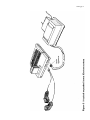
2 Setting up
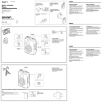
Installing the Electron Plus 1
Unplug your Electron computer from the mains (turn off the mains socket, remove the mains
plug and then the power cable from the side of the Electron). You may also find it convenient to
unplug any other cables (to the television or cassette drive) from your Electron, to make
installation easier.
Warning: Never install or remove the Electron Plus 1 with the power to the Electron turned on.
Turn the Electron upside down with the expansion connector (at the rear of the computer)
towards you and remove the plastic cover from the connector, to expose the edge connector
fingers.
Take the Electron Plus 1 out of its packaging and check that the threaded ends of the two large
screws are not protruding through the base of the Plus 1; if they are, press them down so that the
threaded ends are flush with the base. Turn the Plus 1 upside down and locate the Electron' s
expansion connector in the mouth of the edge connector socket on the Plus 1, and push them
together firmly.
Setting up 3
Using a small coin or screwdriver, screw the two large screws in the Plus 1 into the Electron.
Do not overtighten. If the screws do not engage in the threads in the base of the Electron, try
reseating the Plus 1 on the Electron's expansion connector.
The Plus 1 should now be firmly attached to your Electron. Turn the Electron over and plug the
power supply (and any other cables you may have removed) into the Electron and turn it on.
Check that the Electron still works normally, by loading and running a small program which you
know has run successfully before. If all is not well, refer to chapter 6.
Now you have fitted the Plus 1 to the Electron and checked that the system works, you can
connect your printer, joysticks, games paddles or cartridges.
Using a printer
To connect a printer, you will need an extra mains socket (or an adapter) to power the printer
and an interface cable to connect the printer to the Plus 1. You should be able to obtain a
suitable cable from your dealer.
Put the printer on a stable, flat surface near enough to your Electron so that the interface cable
can reach. Turn both the Electron and the printer off. Connect the printer cable to the printer as
instructed in the printer manual, then connect the other end of the cable to the Plus 1 as follows:
—The printer socket is the wide rectangular socket at the rear of the Plus 1 to the right of the
analogue input socket (viewed from the rear). Insert the printer cable plug in this socket so
that the triangular mark on the socket housing lines up with the similar mark on the plug.
—Turn the printer and Electron on again.
You are now ready to use the printer for simple printing tasks. To turn printing on, type CTRL B
or execute VDU 2 in a program; all output displayed on the screen will then be sent to the printer
as well. To turn printing off, type CTRL C or execute VDU 3 in a program. For full details of
using a printer, see chapter 4.
Using games paddles or joysticks
Only use games paddles or joysticks which are compatible with the Plus 1 (ask your dealer or
see chapter 3). Turn the Electron off and plug the cable into the Plus 1 'analogue in' socket,
which is the smaller socket at the rear to the left of the printer socket The plug and socket are
shaped so they will only fit together
4 Setting up
one way up. Turn the Electron on again and the joysticks or games paddles are now ready for
use with suitable games or can be read from BASIC — see chapter 3 for further details.
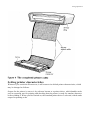
Using cartridges
To use a cartridge produced by Acorn for the Plus 1, you must first plug it into either of the two
shuttered slots in the top of the Plus 1. Insert the cartridge with its label towards you (ie facing
the keyboard), pushing it into the slot so that the right-hand end makes contact first, then
pressing it home until you hear it click into place. The cartridges are designed so that it is very
difficult to insert them the wrong way round.
With a cartridge inserted correctly, either press BREAK (if the Electron was turned on) or
turn the Electron on. Instructions in the use of the cartridges vary; full details will be supplied
with any cartridge you purchase.
Using tape cassettes with the Plus 1
Whenever you use LOAD, SAVE, CHAIN, *LOAD, *RUN or * EXEC, the Plus 1 printer port and
analogue interface are automatically disabled for the duration of that command. If you are
using the BPUT#, BGET#, INPUT# or PRINT# commands in a program, you should use the * F
X163,128,1 command to explicitly disable the printer port and analogue interface before using
the tape, and re-enable them afterwards using * F X163,128,0.
Disconnecting the Plus 1
If you should need to disconnect the Plus 1 for any reason, be careful to turn off the Electron
first, then reverse the sequence of actions used to attach it. Note that the Plus 1 should not be
disconnected and reconnected repeatedly, as this will cause wear of the expansion connector
contacts.
Setting up 5
3 The analogue
interface
The analogue interface is used to measure smoothly varying voltages (analogue inputs)
produced outside the computer, converting them into numbers (digital information) which the
Electron can then use like any other numerical input. This conversion is performed by a circuit
known as an 'analogue to digital converter', or ADC. The analogue inputs are connected via the '
analogue in' socket which is the left-hand socket when viewed from the rear of the Plus 1. This
socket also allows you to detect the position of two two-way switches, normally connected as
the 'fire' buttons on joysticks or games paddles.
Although the analogue interface is most often used for connecting games paddles or joysticks, it
may also be used to measure voltages from other devices such as light-sensitive or heatsensitive transducers, as long as they are electrically compatible (see 'Choosing other analogue
peripherals', below). The analogue interface has a resolution of 8 bits (ie 1 in 256), but generates
numbers in the range 0 to 65280 for compatibility with BBC BASIC.
The Plus 1 can continuously measure up to four voltages, allowing the use of up to four games
paddles, two joysticks, or four separate external voltages at a time. Wherever the analogue
inputs originate, they are treated exactly the same by the analogue interface and computer.
Connecting to the 'analogue in' socket
Analogue peripherals which have been manufactured by Acorn for the Electron may simply be
plugged into the 'analogue in' socket. Before connecting other peripherals, check that they are
electrically compatible (dealt with separately for each type, below) and that the cable used is
wired correctly, ending in a 15-way D-type connector, wired as follows:
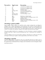
The analogue interface 7
Pin number
1
2
3
4
5
6
7
8
9
10
11
12
13
14
15
Signal name
Description
+5V
0V
0V
CH3
Analogue Gnd
0V
CH1
Analogue Gnd
Not connected
PB1
VREF
CH2
PB0
VREF
CH0
5 volt power for digital circuit
0 volt power for digital circuit
0 volt power for digital circuit
Analogue input 3
0 volt for analogue circuit
0 volt power for digital circuit
Analogue input 1
0 volt for analogue circuit
Pushbutton 1 (digital input)
Voltage reference for analogue circuit (1.8V)
Analogue input 2
Pushbutton 0 (digital input)
Voltage reference for analogue circuit (1.8V)
Analogue input 0
Choosing a games paddle
Games paddles usually consist of a small box with a single rotating knob, providing the
computer with a voltage indicating how far the knob has been rotated. A games paddle can
therefore only provide a single dimension of information to a game, such as a position in the
horizontal or vertical axis of the screen. The games paddle may also have a small pushbutton
switch or 'fire button', providing the computer with a digital 'pressed/not pressed' signal.
The games paddle should have an impedance of at least 10k ohms to match the analogue
circuitry of the Plus 1 and be wired as described above (see `Connecting to the 'analogue in'
socket').
Check the paddle for ease of use and comfort, ideally by connecting it to an Electron in the shop
and using it with the type of game or other program that you will want to use at home.
Choosing a joystick
Joysticks usually consist of a small box with a lever protruding from the top, which is free to
move up to approximately 30 degrees in any direction about a pivot at its base. This position of
the joystick lever is translated into two voltages (one for front/back, one for left/right), so that a
joystick provides two
8 The analogue interface
dimensions of information to the software that is using it. Joysticks will usually also have a
small pushbutton switch or 'fire button', providing the computer with a digital 'pressed/not
pressed' signaL
To make the best use of the analogue interface, you should buy a high resolution joystick with
an impedance of at least 10k ohms, wired as described above (see `Connecting to the 'analogue
in' socket').
Check the joystick for ease of use and comfort, ideally by connecting it to an Electron in the
shop and using it with the type of game or other program that you will want to use at home. You
will probably find a self- centering design more suitable for games playing, but less convenient
for general purpose use.
The model ANH01 joysticks provided by Acorn are ideally suited for use with the Electron
Plus 1.
Choosing other analogue peripherals
Devices other than joysticks and games paddles may be connected to the analogue interface,
provided that they are electrically compatible with it and are wired as described above (see '
Connecting to the 'analogue in' socket'). The peripheral may either generate a DC voltage in the
correct range itself which is proportional to the measurement, or may take the reference voltage
(VREF) from the interface and return a fraction of it which is proportional to the measurement (
ie may act as a potential divider).
If the peripheral uses the reference voltage from the interface:
Minimum impedance of 10k ohms
If the peripheral generates its own voltage:
DC voltage: 0 to 1.8 volts
Current drive: 1 milliamp minimum
The maximum resolution of the analogue to digital conversion is 8 bits (ie the analogue input
will be converted into one of 256 different numbers, depending on the input voltage).
If you wish to measure absolute voltages, you must first calibrate the system against a reliable
voltage reference.
The analogue interface 9
Using the analogue interface from BASIC
The four analogue voltages being read by the Electron are assigned 'channel numbers' in the
range 1 to 4: to read the voltage on a channel, use the BASIC function ADVAL (minimum
abbreviation AD., token = &96). For example
horizontal = ADVAL(1) : vertical = ADVAL(2)
The variables horizontal and vertical will now contain integers in the range 0 to 65280,
proportional to the voltages measured on channels 1 and 2, with V being read as approximately
0 and 1.8V as approximately 65280. The number returned by ADVAL increases by steps of 256
rather than by 1 (ie 0, 256, 512 . . . 65280), to allow for future expansion in the resolution of the
conversion process.
To determine whether the fire buttons on the paddles/joysticks are being pressed, use ADVAL
with a channel number of 0, for example
buttons = ADVAL(0) AND 3
The value of the variable but t on s then tells you which buttons are being pressed as follows:
buttons = 0 means no buttons are being pressed
buttons = 1 means that push button 0 is being pressed
buttons = 2 means that push button 1 is being pressed
buttons = 3 means both push buttons are being pressed
Each analogue input is sampled in turn and converted to the digital result returned by ADVAL, in
order of decreasing channel number. The conversion process takes 10mS ec (ie one hundredth
of a second) per active channel, so with all four channels operating, there will be a delay of
40mSec between changes in the readings. To reduce this delay, you should turn off channels
you are not using, with the *FX16 command, as follows:
*FX16,0 turns all the analogue channels off
*FX16,1 turns channel 1 on and channels 2 to 4 off
*FX16,2 turns channels 1 and 2 on and channels 3 and 4 off
*FX16,3 turns channels 1 to 3 on and channel 4 off
*FX16,4 turns all four channels on
10 The analogue interface
To force a particular channel to be sampled and converted next, use *FX17, <channel>, as
follows:
2010 *FX17,3
2015 REM force sampling and conversion for channel 3
2020 REPEAT : UNTIL ADVAL(0) DIV 256 = 3 : REM wait till
finished channel 3
2030 reading = ADVAL(3):REM get reading from
channel 3
Note that the *FX17 command forces sampling and conversion for all channels from that
specified down to 1, even if they have been turned off with *FX16.
ADVAL(0) DIV 256 returns the number of the last channel to complete sampling and
conversion, or 0 if no channel has yet completed conversion since the last *FX16 or *FX17
command.
Using the analogue interface from assembly language
The functions of the ADVAL keyword in BASIC are provided by calling OSBYTE with A = &80
(128 decimal) and X = a number in the range 0 to 4, which determines the function performed as
follows:
X = 0: on exit Y will contain the number of the last channel sampled and converted, or 0 if no
conversion has yet completed (since the last *FX16 or *FX17 call).
X = 1 to 4: on exit X and Y will contain the last value sampled and converted for the channel
number specified in X; X contains the least significant eight bits and Y contains the most
significant eight bits. The range and significance of this 16-bit integer is as for the value
returned by ADVAL (see 'Using the analogue interface from BASIC').
*FX commands can be performed in assembly language in the usual way, by a call to OSBYTE (
&FFF4). Thus, to set the number of analogue input channels, instead of using *FX16, <
number>, load A with &10 and X with the number, then call OSBYTE; to force a channel to be
sampled and converted (*FX17, < channel>), load A with &11 and X with the channel number,
then call OSBYTE.
Each time the sampling and conversion of an analogue signal is completed, an `event' is
generated. If you wish to detect and act on this event, you must first
The analogue interface 11
place the address of the code to handle it (and any other events you are going to enable) at
location &220 and then enable the event using *FX14,3 or the equivalent assembly language
code (LDA#&E: LDX#3: JSR OSBYTE). The event code passed to your routine for this
event (in A) is 3. For further information, refer to 'Events' in chapter 29 of the Electron User
Guide. To disable handling of this event, use *FX13,3 or the equivalent assembly language
code (LDA#&D: LDX#3: JSR OSBYTE).
4 Using a printer
Choosing a printer
The Electron Plus 1 will work with a wide range of printers using a Centronics® compatible
parallel interface. If in doubt about the suitability of a particular printer, consult your dealer.
A helpful and impartial booklet on choosing printers, entitled USPE C 32a' is available free
from the Council for Educational Technology, 3 Devonshire Street, London W1N 2BA.
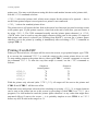
Connecting a printer
To connect a parallel printer to the Plus 1 you will need a suitable cable. These are available
from your dealer as Acorn part number ANG04.
The connections in the cable are as follows:
Signal name
Strobe
Data0
Datal
Data2
Data3
Data4
Data5
Data6
Data7
Acknowledge
Ground
36-way plug pin number
1
2
3
4
5
6
7
8
9
10
19 to31
26-way plug pin number
1
3
5
7
9
11
13
15
17
19
Even numbers 2 to 24
Turn the printer and Electron off and connect the printer to the printer socket (the right-hand
socket when viewed from the rear of the Plus 1), being careful to insert it the right way up (with
the arrow head on the plug facing upwards). Turn the printer and Electron on and you are now
ready to start printing – see `Setting printer characteristics', below.
Using a printer 13
Setting printer characteristics
Whenever you switch the Electron on, it will return to its default printer characteristics, which
may be changed as follows:
Output for the printer is sent to it by software known as a printer driver, which handles tasks
such as queueing text for printing and checking that the printer is ready for another character
before sending it. When you first switch on, the standard printer driver is selected, which sends
output for printing to the
14 Using a printer
printer port. You may switch between using this driver and another known as the 'printer sink',
with the *FX5 command as below:
*FX5,0 selects the 'printer sink', which causes output for the printer to be ignored — this is
useful when printed output is not required or a printer is not connected.
*FX5,1 selects the standard printer driver.
The printer driver will ignore the line feed at the end of text lines and just send a carriage return
to the printer port. If your printer requires a line feed at the end of each line, you can restore it
by using *FX6,0. The *FX6 command actually sets the 'printer ignore character', ie *FX6,
<ASCII code> can be used to stop that single character being sent to the printer. If output to
both printer and screen is selected (see 'Printing from BASIC'), you can get a 'printer ignore
character' out to the printer by sending it immediately after executing a VDU 1 command or
typing CTRL A.
Printing from BASIC
When you first switch on, all output will be sent to the screen; to get printed output, type CTRL
B or execute the command VDU 2 to send the output to the current printer driver as welL
To stop sending output to the printer driver, either type CTRL C (outside a program) or execute
the command VDU 3. To alter the way that output is routed, use the *FX3 command as
follows:
Output to
current printer
*FX3,0
*FX3,10
*FX3,4
*FX3,6
Y
Y
N
N
Output to
screen
Y
N
Y
N
With the printer only selected (after *FX3,10), all output will be sent to the printer and
CTRL B and CTRL C will have no effect
With both screen and printer selected (after switching on or using *FX3,0), a single character
can be sent to the printer but not to the screen by preceding it with CTRL A or VDU 1 (in a
program). Use this method to send the 'printer ignore character' or any codes that might have
unwanted effects if sent to the screen — it is probably simplest to use CTRL A or VDU 1
before any ASCII code in the range 0 to 31.
Using a printer 15
The internal printer buffer
Text sent to the printer is first stored in an area of computer memory known as the internal
printer buffer, and only sent on to the printer when the printer can handle it, usually a line or a
character at a time. If you wish to remove all remaining text from the buffer, you can usually
either press ESCAPE (which empties all the buffers on the system) or use the command
*FX21,3 (which empties the printer buffer only). You can disable the emptying of all
buffers on pressing ESCAPE with the command *FX230,1 and enable it again by
*FX230,0.
Your printer may also have its own printer buffer so that printing may continue for a short while
after using ESCAPE.
Printing from assembly language
The *FX commands given above may be accessed from assembly language in the usual way, ie
by loading A with the command number and X with the number following the comma, then
calling OSBYTE (&FFF4), eg to flush the printer input buffer (*FX21,3):
LDA#&15
LDX#3
JSR &FFF4
Text is printed by selecting printed output (with the assembly language equivalents of *FX3,0
or *FX3,10) and then sending the characters to be printed, one at a time, by loading the
accumulator with the ASCII code and calling OSWRCH (&FFEE) for each character in turn. If
output to screen and printer is selected (*FX3,0), the text to be printed must be preceded by
ASCII 2 (CTRL B) and followed by ASCII 3 (CTRL C) as when using BASIC.
5 Using cartridges
The Plus 1 has two sockets in its upper surface into which a variety of cartridges can be
plugged. These cartridges can provide games, languages, utilities, application programs or other
facilities. Contact your local dealer for a list of cartridges currently available.
Full instructions in the use of these cartridges will be provided with the individual cartridges.
Cartridges should not be installed or removed with the Electron switched on. If you remove or
install a cartridge with the computer turned on, you will need to press BREAK or CTRL
BREAK to restore normal operation.
Games and applications cartridges will usually behave quite differently from language
cartridges, so they are described separately below.
Games and applications: ROM file cartridges
These cartridges are usually designed to load and run the software they contain automatically,
taking over operation of the Electron when it is turned on or after pressing CTRL BREAK, so
that the Electron behaves as a machine dedicated to running that program while the cartridge is
plugged in. To defeat this mechanism, you should press CTRL BREAK, wait about one second,
and then press ESCAPE.
If you have two games/applications cartridges plugged in, the one at the front (nearest the
keyboard) will be the one that 'takes over' the Electron.
The programs and data used by these cartridges are contained in ROMs, accessed by a filing
system similar to the cassette tape filing system you are used to, but much faster and restricted
to reading information only. This is called the ROM filing system.
When you break out of a game, the ROM filing system will be active instead of the cassette
filing system. The commands available are *CAT, LOAD and CHAIN, which have identical
functions to their cassette equivalents, but work with the ROM files.
To use the cassette filing system, select it by typing *TAPE; to use the ROM filing system
again, type *R0M.
Using cartridges 17
With two ROM file cartridges plugged in, to use the software in the cartridge further from the
keyboard, list the files in the ROMs using *CAT and try CHAINing the file listed after !BOOT
for that cartridge.
Languages: paged ROM cartridges
Language cartridges contain alternative programming languages (eg LISP) or other utilities
which the Electron can use instead of the more familiar BASIC language. These ROMs are
called 'paged' ROMs, and are switched by the Electron into the same address range (&8000 to
&C000) as the BASIC ROM they are replacing. This is a very effective way of increasing the
power of your Electron system without using up more RAM memory space.
When you first switch on, if there are no games or applications cartridges plugged in, any
language ROM will be selected in preference to BASIC; if there are two languages, the one
nearer the keyboard will take priority.
To switch between language cartridges and BASIC, use the language name preceded by an
asterisk, eg *BASIC or *LISP.
6 Dealing with
problems
The following is a brief guide to diagnosing problems that may occur when using the expansion
interface, and details of solutions which can be reached without technical assistance or voiding
the warranty. Do not open the Electron computer or Plus 1 cases, as any modifications you
make to this equipment may void the warranty. If in doubt, consult your dealer.
Improving processing speed
With the Plus 1 attached, the Electron has considerable extra processing to do, supervising the
extra facilities. This will usually not be noticeable, but the following steps may be useful to
minimise the speed decrease:
– Use MODEs 4 to 6, as advised in the Electron User Guide.
– Turn off any ADC channels that are not needed (see 'Using the analogue interface from
BASIC', chapter 3).
– Disable all servicing of input and output via the Plus 1, using *FX163,128,1 and reenable servicing with *FX163,128,0 when required.
Problems which may not be faults
Tape filing system commands aren't working– you must switch to the tape filing system (
*TAPE RETURN) after using cartridges (see chapter 5).
Tape loading error – to reduce data errors, avoid using MODEs 0 to 3 while loading and saving
to tape. If you are using the tape for data storage (PRINT#, INPUT#, BPUT#,
BGET#), try the suggestions for improving processing speed given above, for the duration of
the tape operations.
Cannot return to BASIC from a cartridge – some cartridges are protected against piracy by
disabling the BREAK key. To use BASIC, remove the cartridge and then press BREAK. See
chapter 5 for further details.
Programs that cannot run with the Plus 1, but work without it – try the suggestions for
improving processing speed, above.
Dealing with problems 19
Electron malfunctioning
Disconnect the Plus 1. If the computer still does not work, check the power, then take the
Electron and the Plus 1 to your dealer, if the computer works, continue reading.
Clean the edge connector fingers at the rear of the Electron using a nonabrasive rubber and a
soft cloth, then try reconnecting the expansion interface with all the peripherals disconnected. If
the computer still does not work, take the Plus 1 to your dealer, otherwise continue reading.
Reconnect each peripheral (including cartridges) in turn until the original fault returns, cleaning
any contacts that seem dirty or tarnished. If the fault does not return, you have probably
removed it by cleaning and reconnecting the connectors; if the fault does return, continue
reading.
Check the offending peripheral for obvious faults – bent pins in the connector, breaks in cables,
bad seating in the sockets. Try the suggestions under `Peripherals malfunctioning', below.
Return the item to your dealer with a description of the fault.
Peripherals malfunctioning
Check the orientation and seating of the connectors.
If the peripheral has worked before, check if it still works in that situation (eg with the same
software) – if not, try cleaning and reseating the connectors. If the peripheral does work in the
original situation, check the things that are different in the fault situation.
If the peripheral has not worked before, check that you have connected and initialised it
correctly. Try swapping it with another borrowed from a friend or dealer and try it with other
software. If other peripherals work, yours is probably incompatible or faulty (return to dealer);
if other software works with your peripheral, change your software; if changing peripherals and
software does not work, try cleaning the connectors as described above ('Electron
malfunctioning'). Perhaps your peripheral requires special software before it will work correctly,
such as a printer driver.
Appendix A
Summary of new and changed *FX commands and
OSBYTE calls
This Appendix provides a summary of the *FX commands available to users of the Electron
with an expansion unit fitted which either are not documented in the Electron User Guide, or
are documented incompletely. These commands may also be used in assembly language by a
call to OSBYTE; commands which can only be used from assembly language are summarised at
the end of this Appendix.
*FX3,X
Selects the device to which printed output is sent, as follows:
*FX3,0 - To screen and printer
*FX3,10 - To printer only
*FX3,4 - To screen only
*FX3,6 - To neither 4device
*FX5,X
Selects the printer driver, as follows:
*FX5,0 - To 'printer dump'
*FX5,1 - To printer port
*FX6,X
Selects the 'printer ignore character', specified by the ASCII code X
*FX16,X
Selects the number of analogue to digital conversion channels, where X is a number in the
range 0 (no channels) to 4 (all four channels).
*FX17,X
Forces analogue to digital conversion to restart for channels X to 1.
Appendix A 21
*FX21,X
Flushes (empties) the buffer specified by the second parameter, as follows:
*FX21,0 — flushes the keyboard buffer
*FX21,3 — flushes the printer output buffer
*FX21,4-7 — flush sound output buffer number 0, 1, 2 or 3
*FX140,X
Selects the cassette filing system, with any value of X.
*FX163,128,X
Enables or disables input/output through the Plus 1:
*FX163,128,0 — enables printer and ADCs
*FX163,128,1 — disables printer and ADCs
*FX225,X
Changes the effect of typing the user-defined function keys as follows:
*FX225,0 — ignores the function keys
*FX225,1 — the function keys will generate the character string defined by the user
*FX225,2-255 — the function keys will generate an ASCII code based on the second
parameter f1 generates a code one more than the second parameter, f2 a code two more, etc
*FX226,X
Changes the effect of typing function keys in the range A to P, as follows:
*FX226,0 — ignores function keys in this range
*FX226,1 — function keys in this range will generate the BASIC keywords marked on their
keycaps
*FX226,2-255 — function keys in this range will generate an ASCII code based on the
second parameter FUNC A produces a code the same as the second parameter, FUNC B a code
one higher, etc
22 Appendix A
*FX227,X
Changes the effect of typing the remaining function keys (Q to Z plus :
/) as follows:
;
,
-
.
*FX227,0 - ignores function keys in this range
*FX227,1 - function keys in this range will generate the BASIC keywords marked on their
keycaps
*FX227,2-255 - function keys in this range will generate an ASCII code based on the
second parameter: FUNC Q produces a code the same as the second parameter, FUNC R a
code one higher, etc
*FX229, X
Alters the effect of pressing the ESCAPE key as follows:
*FX229,0 - pressing ESCAPE will interrupt the BASIC program
*FX229,1 - pressing ESCAPE will not interrupt the BASIC program, but generate ASCII
code 27 (decimal)
*FX230,X
Enables or disables the normal action of the ESCAPE key, as follows:
*FX230,0 - enables ESCAPE
*FX230,1 - disables ESCAPE
From assembly language only
The following OSBYTE function is only accessible from assembly language, not as a *FX
command:
To read the analogue inputs, call OSBYTE with A = 128 decimal and X = 0 to 4, as follows:
X = 0: returns number of last channel sampled and converted in Y
X = 1-4: returns last reading from channel specified in X, as 16-bit integer in X (low byte) and
Y (high byte)
Notes