1
ScreenBeam Pro
Wireless Display
Receiver
- Business Edition
Model#: SBWD100B (Business Edition)
User Manual
V1.4
Table of Contents
Part I.
Getting Started ......................................................................................................................1
1.1.
Contents in the Box .......................................................................................................1
1.2.
Meeting ScreenBeam Pro .............................................................................................2
1.3.
System Requirements ...................................................................................................2
1.3.1.
Receiver ...............................................................................................................2
1.3.2.
Compatible Devices .............................................................................................2
1.3.3.
Best Known Configurations (BKCs) for Intel Pro WiDi ..........................................3
Part II. Installing the Receiver ...........................................................................................................4
2.1.
Connecting the Receiver to an HDTV ............................................................................4
Part III. Setting Up for the First Time .................................................................................................6
3.1.
Connecting via Windows 8.1 .........................................................................................6
3.2.
Connecting via Windows 10 ........................................................................................10
3.3.
Connecting via Intel® WiDi App (Gen 4)......................................................................13
3.4.
Connecting via Intel® Pro WiDi App (Gen 6) ...............................................................16
3.5.
Tips for Optimal Performance .....................................................................................20
Part IV. Control and Display .............................................................................................................21
4.1.
Intel Pro WiDi and Managed Meeting.........................................................................21
4.2.
Display Mode ..............................................................................................................22
4.3.
USB over Network .......................................................................................................22
Part V. Device Management for IT Administrator...........................................................................24
5.1.
Log into the Local Management Web Server ..............................................................24
5.1.1.
When Autonomous GO is Enabled ....................................................................24
5.1.2.
When Autonomous GO is Disabled ...................................................................25
5.1.2.1. When SSID Broadcast is Enabled ...............................................................25
5.1.2.2. When SSID Broadcast is Disabled...............................................................26
5.1.3.
Log Out ..............................................................................................................30
5.2.
Changing Local Management Console’s Display Language .........................................30
5.3.
Configuring the Receiver .............................................................................................31
5.3.1.
Renaming the Receiver ......................................................................................31
5.3.2.
Setting up Login Username and Password for the Local Management Console
32
5.3.3.
Setting up the Receiver’s Display Language ......................................................32
5.3.4.
Setting up Managed Meetings...........................................................................33
5.3.5.
Setting up Inactive Source Grace Period for Managed Meetings ......................34
5.3.6.
Setting up Moderated Mode for Managed Meetings........................................34
5.3.7.
Setting up PIN Pairing Method ..........................................................................35
5.3.8.
Managing HDMI/VGA Port Output ....................................................................36
5.3.9.
Setting up WiDi Lower Bandwidth .....................................................................37
5.3.10. Setting up Force EDID at RTSP M3 .....................................................................38
5.3.11. Setting up HDCP Encryption ..............................................................................39
5.3.12. Setting up the VGA Compatibility Mode............................................................40
5.3.13. Setting up USB Local Access ..............................................................................40
5.3.14. Adjusting TV Screen Size ....................................................................................41
5.3.15. Setting up Output Aspect Ratio .........................................................................42
5.3.16. Setting up One Touch Play (HDMI-CEC) .............................................................43
5.3.17. Updating the Receiver’s Background Image ......................................................43
5.3.18. Updating the Receiver’s Screensaver Image......................................................45
5.3.19. Setting up Network Information Display on TV Screen .....................................46
5.3.20. Setting up Autonomous Group Owner (AGO) ...................................................47
5.3.21. Setting up Communication Channel ..................................................................48
5.3.22. Setting up Group Owner Intent .........................................................................49
5.3.23. Setting up P2P Network Parameters .................................................................50
5.3.24. Setting up Wireless Network Parameters ..........................................................51
5.3.25. Modifying the Receiver’s Wireless Network Name (SSID).................................52
5.3.26. Setting up Broadcast Network Name ................................................................53
5.3.27. Setting up Wireless Connection Properties .......................................................54
5.3.28. Setting up the Receiver’s IP Address .................................................................55
5.3.29. Specifying a DNS Server for the Receiver ..........................................................56
5.3.30. Specifying the ScreenBeam CMS for the Receiver.............................................57
5.3.31. Rebooting the Receiver .....................................................................................58
5.3.32. Resetting the Receiver to Default ......................................................................58
5.4.
Upgrading the Receiver ...............................................................................................59
Part VI.
FAQs and Troubleshooting ..........................................................................................61
6.1.
FAQ ..............................................................................................................................61
6.2.
Troubleshooting ..........................................................................................................63
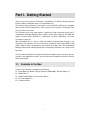
Part I. Getting Started
Thank you for your purchase of Actiontec’s ScreenBeam Pro Wireless Display Receiver
Business Edition (hereinafter refer to as “ScreenBeam Pro”).
The Receiver lets you wirelessly stream what’s on your Intel WiDi or Miracast™ compatible
device to your HDTV, including movies, videos, photos, music, and more. The Receiver frees
your eyes from a tiny screen.
The Receiver boasts some great features, including fast setup, enhanced security and IT
manageability, Managed Meetings (Gen 6 WiDi), smooth video playback, full 1080p HD
support, ultra-low delay, Windows 8.1 optimization, versatile compatibility, low power
consumption, and more.
With ScreenBeam Pro, it's easy to make presentations and impromptu meetings in the
conference room a breeze, as users don't need to scramble to find the right HDMI or VGA
cable in order to share a spreadsheet or presentation on the big screen. And the Managed
Meetings feature allows meeting participants to interactively share their own screens on the
big screen.
This user manual will take you through the procedures needed to install, connect to, operate,
configure, and upgrade the receiver, and also describe a few different possible scenarios
about locating faults.
1.1. Contents in the Box
Contents in the Receiver’s package are listed below:
ScreenBeam Pro Wireless Display Receiver (SBWD100B) - Business Edition (1)
HDMI Cable (1)
HDMI-to-VGA Adapter & 3.5mm audio cable (1)
AC Power Adapter (1)
Installation Guide
1
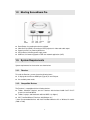
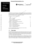
1.2. Meeting ScreenBeam Pro
Reset Button, for resetting the device to default
Video Out Port (HDMI), connecting to HDTV/projector for video and audio output
Power Input Port, for powering the device
LED Indicator, indicating power supply status
USB Port, for firmware upgrade or USB over network application (UoIP)
1.3. System Requirements
System requirements for the receiver are shown below:
1.3.1. Receiver
To install the Receiver, you must have the following items:
A display device with one HDMI port (Type A) or one VGA port
An available power outlet
1.3.2. Compatible Devices
The Receiver is compatible with the following devices:
Tablets, Ultrabook™ devices, and 2-in-1 devices with the latest Intel® Core™ vPro™
processors and Intel WiDi 6
Tablets, Laptops, and Notebooks with Intel WiDi 4 (or higher)*
Wi-Fi Certified Miracast™ devices with Windows 8.1*
* Note: Recommended devices with Intel Dual-Band Wireless-AC or Wireless-N models
(7260 or 7265)
2
1.3.3. Best Known Configurations (BKCs) for Intel Pro WiDi
For optimal experience with Intel Pro WiDi, we recommend to update your system drivers
and Intel WiDi application to the latest versions provided by Intel. You can find the latest
version by visiting Intel’s wireless display support website
http://www.intel.com/p/en_US/support/highlights/wireless/wireless-display/
•
•
•
•
•
4th Gen or Higher Intel Core vPro* Platform with pGFX
Core m, I5, or i7 with vPro
Graphics Package: v15.36.x.x (or higher)
Wireless Driver: v10.18.x.x (or higher)
Intel WiDi App: v6.x.x.x (or higher)
3
Part II. Installing the Receiver
This chapter explains how to connect the Receiver to an HDTV. Make sure you have all the
contents from the Receiver’s package available before starting.
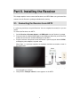
2.1. Connecting the Receiver to an HDTV
It is quite easy and fast to set up the Receiver. You can complete the connection in just one
minute.
To connect the Receiver to an HDTV:
1. Get the Receiver, AC power adapter, and HDMI cable from the Receiver’s package.
2. Plug one end of the supplied HDMI cable into the HDMI port (Video Out) on the Receiver,
and the other end into an available HDMI port on the HDTV.
3. Plug the connector of the power cord to the Receiver’s power input port labeled "5V DC",
and plug the power adapter to a power outlet.
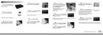
When Steps 1, 2, and 3 are complete, the hardware should be connected as shown in
the figure below:
4.
5.
Turn on the HDTV and set it to display the input from the correct HDMI port (the one you
have plugged into in Step 2).
Verify that the “Ready to connect” screen appears on the HDTV.
4
The Receiver is connected to the HDTV, and it is ready for use.
Note: Connections to other display devices are similar.
5
Part III.
Setting Up for the First
Time
This chapter explains how to connect ScreenBeam Pro for the first time to the source device.
There are several source device options: Intel WiDi (Intel Pro WiDi), Windows 8.1, and
Windows 10.
For Windows 8.1 devices, please proceed to Section 3.1. Connecting via Windows 8.1;
For Windows 10 devices, please proceed to Section 3.2. Connecting via Windows 10;
For Windows 7/8 devices (Gen 4 WiDi), please proceed to Section 3.3. Connecting via
Intel® WiDi App (Gen 4);
For Intel Pro WiDi (Gen 6) devices, please proceed to Section 3.4. Connecting via
Intel® Pro WiDi App (Gen 6).
3.1. Connecting via Windows 8.1
This section explains how to connect a device running Windows 8.1 to ScreenBeam Pro.
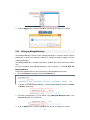
1. From the Windows desktop, go to the Charms menu and select Devices to open the
Devices menu. You can also use the shortcut keys, Windows logo + K.
2.
From the Devices menu, click Project.
6
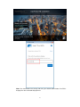
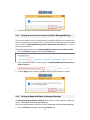
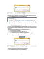
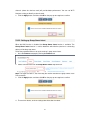
3.
From the Project menu, select Add a wireless display. Windows will search for
available devices.
Note: If you are running Windows 8.1 and the screens above do not appear, go to
http://www.actiontec.com/widi81 for the latest software update. Or, you can update your
Windows 8.1 via the Windows Update application.
4. Select your receiver from the device list.
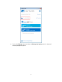
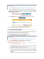
5.
A PIN entry box is displayed on the screen of your Windows 8.1 device, and a PIN code
and host name (QA-PC01 in this example) of the connecting device are displayed on
the HDTV. Type the PIN in the PIN entry box on your device, and then click Next.
7
6.
Note: You should obtain the security PIN from your network administrator if no PIN is
displayed on the connected display device.
Your device will connect to the receiver within a few seconds.
8
Note:
Intel Pro WiDi (Gen 6) will run automatically if your device is compatible with Intel
Pro WiDi (Gen 6) and has the app installed.
Your device’s screen will be displayed on the HDTV in about ten seconds if Intel
WiDi (Gen 6)/Intel Pro WiDi (Gen 6) app is not installed on your device. Refer to
5.3.5. Setting up Inactive Source Grace Period for Managed Meetings for detail.
9
3.2. Connecting via Windows 10
This section explains how to connect a device running Windows 10 to ScreenBeam Pro.
1.
Press the shortcut keys, Windows logo
wireless display receiver list.
+ K, on your keyboard to display the
Note: There are other ways to open the wireless display receiver list:
Click the Start button, and then select Settings > Devices > Connected devices >
Add a device to open the wireless display receiver list.
Click the Notification icon on the task bar or press the shortcut keys, Windows
logo
+ A, to open the Action Center, and then select Connect to open the
wireless display receiver list.
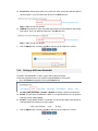
2.
Press the shortcut keys, Windows logo
+ P, to open the Project menu, and
then select Connect to a wireless display to open the wireless display receiver
list.
Select your receiver from the device list.
10
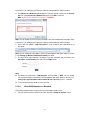
3.
A PIN entry box is displayed on the screen of your Windows 10 device, and a PIN code
and host name (QA-PC01 in this example) of the connecting device are displayed on
the HDTV. Type the PIN in the PIN entry box on your device, and then click Connect.
11
4.
Note: You should obtain the security PIN from your network administrator if no PIN is
displayed on the connected display device.
Your device will connect to the receiver within a few seconds.
Note:
Intel Pro WiDi (Gen 6) will run automatically if your device is compatible with Intel
12
Pro WiDi (Gen 6) and has the app installed.
Your device’s screen will be displayed on the HDTV in about ten seconds if Intel
WiDi (Gen 6)/Intel Pro WiDi (Gen 6) app is not installed on your device. Refer to
5.3.5. Setting up Inactive Source Grace Period for Managed Meetings for detail.
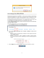
3.3. Connecting via Intel® WiDi App (Gen 4)
This section explains how to connect a device running Intel's WiDi application to the receiver.
Follow the procedure below to connect your device to the receiver:
1. Launch the Intel Wireless Display application on the device. To find the application, go
to Windows Search on the device and search for “Intel WiDi”.
2. The Intel WiDi application scans for available receivers automatically. Select your
receiver and click Connect. (The “Connect Automatically” checkbox is optional.)
3.
Note: If your receiver is not found, you can click the Scan button to scan again.
A PIN entry box is displayed on the screen of the WiDi device, and a PIN code and host
name (QA-PC01 in this example) of the connecting device are displayed on the HDTV.
Type the PIN in the PIN entry box on the WiDi device, and then click Connect.
13
Note: You should obtain the security PIN from your network administrator if no PIN is
displayed on the connected display device.
4.
Within a few seconds, your device will connect to the receiver.
14
5.
A "Connection Successful" screen appears on the device's screen. Click Finished,
and the device’s screen will be displayed on the HDTV in about ten seconds.
15
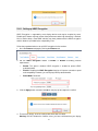
3.4. Connecting via Intel® Pro WiDi App (Gen 6)
ScreenBeam Pro supports Managed Meetings, which is only available with Intel® Pro WiDi.
To use this feature, ScreenBeam Pro must have the AGO feature enabled.
Note:
To use the Intel® Pro WiDi Managed Meeting feature, you must install the Intel Pro WiDi
software on an Intel® Haswell or better system with Intel® Core™ vPro™ processor.
For details about AGO settings, refer to Section 5.3.20. Setting up Autonomous Group
Owner (AGO).
Follow the procedure below to connect your device to ScreenBeam Pro:
1. Launch the Intel® Pro WiDi application on your device.
2. The Intel® Pro WiDi application scans for available receivers automatically. Select your
receiver to start the connection procedure.
3.
A PIN entry box is displayed on the screen of the WiDi device, and a PIN code and host
name (QA-PC01 in this example) of the connecting device are displayed on the HDTV.
Type the PIN in the PIN entry box on the WiDi device, and then click Connect.
16
Note: You should obtain the security PIN from your network administrator if no PIN is
displayed on the connected display device.
17
4.
Your WiDi device will connect to the receiver within a few seconds.
5.
Click the Duplicate button to mirror your screen on the HDTV.
18
6.
Or, click the Manage button and select the Manage the display option for advanced
meeting management options.
19
3.5. Tips for Optimal Performance
For optimal performance, you can try these tips:
•
Keep the Receiver within line-of-sight of the source device. Doing this will help ensure
the Receiver receives the best possible signal.
•
The Receiver's optimal wireless range is within 30 feet from the source device. However,
actual range and effectiveness depends on many factors, including other sources of
interference and the building materials used in the surrounding structure.
•
Avoid placing the receiver near wireless interference sources, such as electric fans,
items with motors, microwave ovens, cordless phones.
20
Part IV. Control and Display
This chapter describes the display modes and control options that are supported by the
Receiver.
4.1. Intel Pro WiDi and Managed Meeting
ScreenBeam Pro supports the Managed Meetings feature, which is provided with Intel Pro
WiDi. The Managed Meetings feature allows meeting participants to share their screens
interactively, or allow the moderator (the user who has selected the “Manage the display”
option) to manage other participants.
There are three meeting modes available when the Managed Meetings function is enabled.
Exclusive mode: No one else can share or take control.
Interactive mode: Other people can share their screen.
Moderated mode: You control sharing.
Note: To use the Managed Meetings function, the AGO function must be enabled. Refer to
Section 5.3.20. Setting up Autonomous Group Owner (AGO) for details.
Note: Intel® Pro WiDi requires an Haswell system, or better.
Note: For detailed operation and related information about Intel Pro WiDi, refer to
http://www.actiontec.com/prowidi.
21
4.2. Display Mode
The Receiver supports three display modes when connected with a compatible wireless
display application (Intel WiDi or Windows 8.1/10 Project, for example).
In Windows, press the Windows logo and P keys simultaneously (
display options and select the desired display mode from the options.
+ P) to launch the
Duplicate
The Duplicate mode is used to display the same content on both the device's screen and
the HDTV simultaneously.
Note: There may be minor delay between the content displayed on the HDTV screen
compared to the device’s screen. This is due to the current state of wireless display
technology.
Extend
The Extend mode creates a single, extended "screen" between the source device and the
HDTV. When in the Extend mode, dragging windows to the right side of the device's screen
displays those windows on the HDTV, while dragging windows to the left of the HDTV screen
displays them back on the device's screen. This mode allows users to display selected
content on the HDTV, while all other windows remain on the device's screen. When this mode
is first selected, the HDTV displays only the Windows desktop.
Second Screen Only
The Second Screen Only mode causes the HDTV to be the only display for the device.
You’ll see everything on the connected screen, and your device’s screen will be blank.
4.3. USB over Network
The Receiver’s USB over Network (UoIP) feature allows the use of USB HID peripheral
devices, either from the source device or from the USB device side. To connect a USB
keyboard, mouse, or trackpad:
1. Log into the receiver’s local web management console, and set the UoIP or UIBC feature
to Enable. Refer to Section 5.3.13. Setting up USB Local Access for details.
2. Plug the device into the Receiver’s USB port and wait for the device to be detected. This
22
may take 10-15 seconds.
3. Use the USB keyboard, mouse, or trackpad to control the source device.
Note: UoIP is compatible with Intel WiDi only.
23
Part V. Device Management for IT
Administrator
ScreenBeam Pro provides a local management web server to manage the device. With the
web server, IT administrators can setup, configure and upgrade the receiver.
5.1. Log into the Local Management Web Server
There are two methods to log into the local management web server.
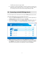
5.1.1. When Autonomous GO is Enabled
When Autonomous GO is enabled, you can log into the local management web server
through "http://192.168.16.1". You must connect your device to the receiver, and then access
the URL address with a web browser.
Note: http://192.168.16.1 is the default URL address. You can modify this URL address in
the local management web page. Refer to Section 5.3.23. Setting up P2P Network
Parameters for detail.
Follow the procedure below to log into the local management server when AGO is enabled.
1. Connect your device to ScreenBeam Pro.
2. Access the URL address (http://192.168.16.1) with a web browser on your device.
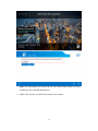
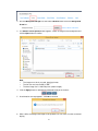
3. The web server login interface appears. Type the username and password in the
Username and Password boxes and click the Login button.
Note:
By default, the Username is “Administrator” and Password is “WiDi”. You can modify
the username and password in the local management web page. Refer to Section 5.3.2.
Setting up Login Username and Password for the Local Management for detail.
The username and password are case sensitive.
When Autonomous GO is enabled, the SSID of the receiver is reserved.
24
5.1.2. When Autonomous GO is Disabled
When Autonomous GO is disabled, you must connect your device to the receiver’s SSID,
and then access the URL address (it is "http://192.168.51.1" by default) with a web browser.
Note: You can set the receiver’s network information to be displayed on the Ready to
connect screen. Refer to Section 5.3.19. Setting up Network Information Display on TV
Screen for detail.
There are two situations: when the SSID broadcast is enabled and when it is disabled.
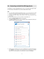
5.1.2.1.
When SSID Broadcast is Enabled
Follow the procedure below to log into the local management web server:
1. Connect to the receiver’s SSID from a wireless-enabled laptop (or other devices with WiFi access ability and a web browser). You can find the SSID in the lower part of the Ready
to connect screen.
Note: If the network information display is disabled, you can find the SSID of the receiver on
the Wi-Fi connection list by following these tips: the SSID of the receiver is in this format
“Actiontec-SBWD-xxxxxx”, and the last four characters are the same as the last four of the
receiver name.
2. Click the wireless network icon to open the Networks page, and select the receiver’s
SSID.
Note: You can modify this SSID and its password in the local management web page. Refer
25
to Section 5.3.25. Modifying the Receiver’s Wireless Network Name (SSID) for detail.
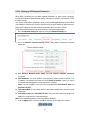
3. The Connect to a Network window appears. Type the network security key in Security
key box of the Connect to a Network dialog box. Click OK to continue.
Note: By default, the network security key is “12345678”.
Note: You can modify this SSID and its password in the local management web page. Refer
to Section 5.3.25. Modifying the Receiver’s Wireless Network Name (SSID) for detail.
4. Access the URL address ("http://192.168.51.1" in this example) with a web browser on
the laptop.
Note: You can modify this URL address in the local management web page. Refer to Section
5.3.24. Setting up Wireless Network Parameters for detail.
5. The web server login interface is displayed. Type the username and password in the
Username and Password boxes and click the Login button.
Note:
By default, the Username is “Administrator” and Password is “WiDi”. You can modify
the username and password in the local management web page. Refer to Section 5.3.2.
Setting up Login Username and Password for the Local Management for detail.
The username and password are case sensitive.
5.1.2.2.
When SSID Broadcast is Disabled
Follow the procedure below to log into the local management web server:
1. You can find the receiver’s SSID in the lower part of the Ready to connect screen.
26
2. Right-click the Wi-Fi network icon in the Notification Area of your source device and select
Open Network and Sharing Center.
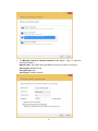
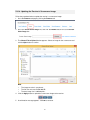
3. The Network and Sharing Center window appears. Click Set up a new connection or
network.
4. The Set up a new connection or network window appears. Choose the Manually
connect to a wireless network option.
27
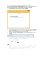
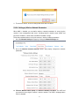
5. The Manually connect to a wireless network window appears. Type in or select the
following information.
Network name: The SSID of the ScreenBeam Pro receiver you wish to connect to.
Security type: WPA2 Personal
Encryption type: AES
Security key: 12345678 (default)
28
6. Check Connect even if the network is not broadcasting. Click Next.
Note: Check Start this connection automatically if you want to automatically connect to
this wireless network when it is in range. Otherwise, leave this box unchecked.
7. You have added the receiver’s SSID successfully. Click Close.
8. Your device will connect to the SSID automatically if you have selected “Start this
connection automatically”. Otherwise, go to the Networks page by clicking the
Network icon in the Notification Area and connect to the SSID.
9. Access the URL address ("http://192.168.51.1" in this example) with a web browser on
the laptop.
10. The web server login interface appears. Type the username and password in the
Username and Password boxes and click the Login button.
Note:
By default, the Username is “Administrator” and Password is “WiDi”. You can modify
the username and password in the local management web page. Refer to Section 5.3.2.
Setting up Login Username and Password for the Local Management for detail.
The username and password are case sensitive.
29
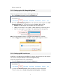
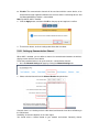
5.1.3. Log Out
1. Go to the Logout tab page by clicking the Logout tab.
2. Click the “Yes” button to log out.
3. You will log out from the local management web page immediately.
5.2. Changing Local Management Console’s Display
Language
Before you log into the local management console, you can change the console’s display
language. Follow the procedure below:
1. Open the local management console’s login page. Refer to Section 5.1. Log into the
Local Management Web Server for details.
2.
On the upper right corner of the screen, select your language. Available languages are
English, Simplified Chinese, Traditional Chinese, Japanese, French, German, Dutch,
Korean, Spanish, Italian, and Russian.
30
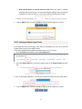
3. The display language changes immediately.
Note: This setting changes the webpage’s display language only.
5.3. Configuring the Receiver
After you have logged into the web server, you can configure ScreenBeam Pro on the
webpage.
5.3.1. Renaming the Receiver
Follow the procedure below to rename the receiver:
1. Go to the Device Configuration tab page by clicking the Device Configuration tab.
2. Set the Device Name Access to Enable.
3. Type a new name in the Device Name box.
4. Click the Apply button, and then click OK on the pop-up message box to confirm.
31
5.3.2. Setting up Login Username and Password for the Local
Management Console
You can modify the user name and password for logging into the local management server.
Follow the procedure below to modify the receiver’s login username and password:
1. Go to the Device Configuration tab page by clicking the Device Configuration tab.
2. Type new username and password in the Administrator Username and Administrator
Password boxes.
3. Click the Apply button, and then click OK on the pop-up message box to confirm.
5.3.3. Setting up the Receiver’s Display Language
Follow the procedure below to change the receiver’s display language:
1. Go to the Device Configuration tab page by clicking the Device Configuration tab.
2. Choose a desired language from the Display Language drop-down box.
Currently available languages are Simplified Chinese, Traditional Chinese, Dutch,
English, French, German, Italian, Japanese, Korean, Russian, and Spanish.
Note: This setting will change the display language on the TV screen.
32
3. Click the Apply button, and then click OK on the pop-up message box to confirm.
5.3.4. Setting up Managed Meetings
The Managed Meetings function allows meeting participants to share the wireless display
interactively, or allows the meeting moderator to manage the display requests from the
meeting participants.
The Managed Meetings is available when AGO is enabled. And it works with Intel Pro WiDi
only.
For more information about Managed Meetings, refer to Section 4.1. Intel Pro WiDi and
Managed Meeting.
Follow the procedure below to set up the receiver’s Managed Meetings function:
1. Go to the Features tab page by clicking the Features tab.
2. To enable or disable Managed Meetings, set the Managed Meetings function to Enable
or Disable, respectively.
3. For better communication, you can define a port (Managed Meetings Port) for the
Managed Meetings, as shown below:
4. Click the Apply button, and then click OK on the pop-up message box to confirm.
33
5. The receiver reboots, and new settings take effect after the reboot.
5.3.5. Setting up Inactive Source Grace Period for Managed Meetings
For the source devices that do not have the Intel Pro WiDi or WiDi (Gen 6) installed, these
devices will present on the display device in a short period of time after they have connected
to the receiver. The Managed Meetings Inactive Source Grace Period feature is used to
set up this period of time.
Follow the procedure below to set up Managed Meetings Inactive Source Grace Period:
1. Go to the Features tab page by clicking the Features tab.
2. Enter a period of time (from 1 to 30 seconds) in the Managed Meetings Inactive Source
Grace Period box.
3. Click the Apply button, and then click OK on the pop-up message box to confirm.
5.3.6. Setting up Moderated Mode for Managed Meetings
The Managed Meetings Modes Disabled feature can be used to disable or enable the
receiver’s Moderated mode for Managed Meetings.
Follow the procedure below to set up the receiver’s Moderated mode for Managed Meetings:
1. Go to the Features tab page by clicking the Features tab.
34
2. To enable or disable the receiver’s Moderated mode for Managed Meetings, set the
Managed Meetings Modes Disabled feature to Nothing is disabled or Moderated
mode is disabled, respectively.
3. Click the Apply button, and then click OK on the pop-up message box to confirm.
4. The receiver reboots, and new settings take effect after the reboot.
5.3.7. Setting up PIN Pairing Method
For security purpose, you may be required to connect to ScreenBeam Pro with a PIN. You
can define the PIN pairing method in the local management page.
Follow the procedure below to set up the receiver’s PIN pairing methods:
1. Go to the Features tab page by clicking the Features tab.
2. Set the Force PIN Pairing on First Connection feature to On or Off.
Select "Off" to disable the PIN enforcement function. PIN entry or PBC is used when
connecting your device to the receiver for the first time.
Select "On" to enable the PIN enforcement function. In this case, you must enter a
PIN code on the device connecting to the receiver for the first time. When this
function is enabled, the system provides two PIN generation methods: Random
and Static.
Note: Some wireless display source devices do not support PIN entry and may not
35
be able to connect with the ScreenBeam receiver if this mode is enabled. Refer to
the device’s user manual for detail about enabling the PIN connection.
Random: A PIN code is generated randomly by the system and displayed on
the connected HDTV/projector.
Static: Users can define seven (7) digits, and then the system generates an
eight (8) digit PIN with that seven digits included.
Enter seven (7) digits in the Static PIN box, and the system generates the
eighth (8th) digit. This PIN will not be displayed on the connected display.
3. Click the Apply button, and then click OK on the pop-up message box to confirm.
Note: If you have selected Static, do remember to check the PIN code in the Static PIN field
and write it down before clicking OK.
4. The receiver reboots, and new settings take effect after the reboot.
5.3.8. Managing HDMI/VGA Port Output
The HDMI/VGA Port Power management feature provides flexible options to control the
HDMI outputs. Follow the procedure below to manage the receiver’s HDMI/VGA port output:
1. Go to the Features tab page by clicking the Features tab.
2. Select the desired option in the HDMI/VGA Port Power management drop-down box.
There are three options: Always On, Screensaver, and HDMI Off.
Always On: Selecting this option, the HDMI output is always on.
36
Screensaver: Selecting this option, the system will run the screensaver after the defined
idle time expires. Users can define the idle time in the Wait time box.
Note: 5-9999 seconds are allowed.
HDMI Off: Selecting this option, the HDMI output will be turned off after the defined idle
time expires. Users can define the idle time in the Wait time box.
Note: 5-9999 seconds are allowed.
3. Click the Apply button, and then click OK on the pop-up message box to confirm.
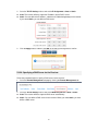
5.3.9. Setting up WiDi Lower Bandwidth
The WiDi Lower Bandwidth is used to control video quality and speed.
Follow the procedure below to set up WiDi Lower Bandwidth for the receiver:
1. Go to the Features tab page by clicking the Features tab.
2. Set WiDi Lower Bandwidth to Enable or Disable according to practical requirements.
Enable: This will limit the bandwidth for WiDi. In a congested network, this can produce
relatively smooth video playback.
Disable: The bandwidth for WiDi is not limited. This will produce better video quality for
video playback when working in a clean network.
3. Click the Apply button, and then click OK on the pop-up message box to confirm.
37
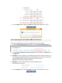
5.3.10. Setting up Force EDID at RTSP M3
Extended display identification data (EDID) is a data structure provided by a digital display
to describe its capabilities to a video source (e.g. graphics card or set-top box). It is what
enables a modern personal computer to know what kinds of monitors are connected to it.
If the EDID data provided by the display device is not compatible with the video source (such
as ScreenBeam Pro), the video display may show a distorted or blank screen.
The Force EDID at RTSP M3 feature is used to override the information from the EDID data,
and outputs 1080p/i resolution.
Follow the procedure below to set up Force EDID at RTSP M3:
1. Go to the Features tab page by clicking the Features tab.
2. Set the Force EDID at RTSP M3 feature to Enable or Disable according practical
requirements.
Enable: Information from EDID data is overridden. The video output of the receiver
is set to 1080p/i resolution.
Disable: The EDID data is used for negotiation to decide an output resolution.
Generally, the maximum resolution supported by the receiver and the display device
is used.
3. Click the Apply button, and then click OK on the pop-up message box to confirm.
38
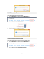
5.3.11. Setting up HDCP Encryption
HDCP Encryption is supported by most display devices and may be required by some.
Disabling this feature may improve the video performance when high interactivity is desired.
Also in certain setups, some HDMI switches may have problem with the HDCP encryption
and this feature is provided for the compatibility issue.
Follow the procedure below to set up HDCP encryption for the receiver:
1. Go to the Features tab page by clicking the Features tab.
2. Set the HDCP Encryption feature to Enable or Disable according practical
requirements.
Enable: This option is default. HDCP encryption is enabled to protect HDCP
protected media.
Disable: Disabling the HDCP Encryption function will improve connection speed
and compatibility. However, you cannot play HDCP protected media.
Demo Mode: Reserved.
3. Click the Apply button, and then click OK on the pop-up message box to confirm.
4. The receiver reboots, and new settings take effect after the reboot.
Warning: DO NOT disable this feature, unless you have confirmed that your display
39
device supports that.
5.3.12. Setting up the VGA Compatibility Mode
Follow the procedure below to select a VGA compatibility mode:
1. Go to the Features tab page by clicking the Features tab.
2. Go to the VGA Compatibility Mode line, and select the desired option in the VGA
Compatibility Mode box. There are three options: Disable, 1080, and 720.
Disable: The video output is in consistence with the source device.
1080: The video output is set to 1080p or 1080i, depending on the display device.
720: The video output is set to 720p or 720i, depending on the display device.
Note: The VGA compatibility mode is not available when HDMI-CEC is enabled.
3. Click the Apply button, and then click OK on the pop-up message box to confirm.
5.3.13. Setting up USB Local Access
A USB port is provided on the ScreenBeam Pro wireless display receiver for multi-purpose
uses. You can set up the USB port in the local management page.
Follow the procedure below to set up the USB port:
1. Go to the Features tab page by clicking the Features tab.
2.
Configure the USB Local Access feature according to practical requirements.
There are three options: Disable, Only allow firmware update, and Enable.
40
3.
Disable: Select "Disable" to disable the USB port on the receiver.
Only allow firmware update: Select "Only allow firmware update" to allow users to
update firmware for the receiver through the USB port.
Enable: Select "Enable" to allow full functions of the USB port. In this case, users not
only can upgrade the receiver, but also can control the source device by connecting a
keyboard/mouse to the receiver via the USB port (with the User Input Back Channel
(UIBC) or USB over IP (UoIP) function enabled).
UIBC: The connected keyboard/mouse does not support combo keys or mouse
right-click.
Note: Working with a Windows 10 source device, combo keys and mouse rightclick are also supported.
UoIP: The connected keyboard/mouse supports full functions.
Note: UoIP is compatible with Intel WiDi only.
Click the Apply button, and then click OK on the pop-up message box to confirm.
5.3.14. Adjusting TV Screen Size
If edges of the device screen cannot be seen on the HDTV or you can see black edges, you
can adjust the TV screen size (overscan).
Follow the procedure below to adjust the size of your TV screen:
1. Go to the Features tab page by clicking the Features tab.
2. Go to the TV Screen Size (Overscan Settings) line, and select the desired option in the
TV Screen Size (Overscan Settings) drop-down box.
The value for TV screen size ranges from 0 to 25. The larger the value is, the bigger
the screen will be.
41
Allow source device to override overscan value: When this option is enabled
(checked), the overscan value is in consistence with the setting on the source device.
Otherwise, the overscan value is in consistence with the setting on the receiver.
3. Click the Apply button, and then click OK on the pop-up message box to confirm.
5.3.15. Setting up Output Aspect Ratio
If the output does not fit your display screen due to wrong aspect ratio, you can try selecting
a proper aspect ratio for your display screen.
Follow the procedure below to adjust the aspect ratio for your TV screen:
1. Go to the Features tab page by clicking the Features tab.
2. Go to the Aspect Ratio line, and select a proper option in the Aspect Ratio drop-down
box.
In case of selecting the 4:3 option, you can also fine tune the horizontal and vertical offsets.
3. Click the Apply button, and then click OK on the pop-up message box to confirm.
42
5.3.16. Setting up One Touch Play (HDMI-CEC)
Follow the procedure below to set up the receiver’s One Touch Play (HDMI-CEC) function:
1. Go to the Features tab page by clicking the Features tab.
2. Go to the One Touch Play (HDMI-CEC) line, and set the One Touch Play (HDMI-CEC)
feature to On or Off.
There are two options: On, and Off. After this function is enabled, the receiver can wake up
the connected display device and the display device will switch to the source that the receiver
connects to.
The display device will be waked up in one of the following conditions:
a. when the receiver is powered on;
b. when a connection to the receiver is established; and
c. when a power-on receiver is connected to the display device.
Note: The display device must support HDMI-CEC, and this function is enabled.
3. Click the Apply button, and then click OK on the pop-up message box to confirm.
5.3.17. Updating the Receiver’s Background Image
Follow the procedure below to update the receiver’s background:
1. Go to the Features tab page by clicking the Features tab.
43
2. Go to the Background Image line, and click the Browse button next to the Background
Image box.
3. The Choose File to Upload window appears. Select an image for the background and
click the Open button to confirm.
Note:
The images must be in .png and .jpeg/.jpg formats.
The file size must not exceed 2.5 MB.
The best image size is 1280*720 pixels (width x height).
4. Click the Apply button to upload the background image to the receiver.
5. A confirmation message appears. Click OK to continue.
6. After a while, the background image will be updated. You can check it on the connected
display.
44
5.3.18. Updating the Receiver’s Screensaver Image
Follow the procedure below to update the receiver’s screensaver image:
1. Go to the Features tab page by clicking the Features tab.
2. Go to the Screen Saver Image line, and click the Browse button next to the Screen
Saver Image box.
3. The Choose File to Upload window appears. Select an image for the screensaver and
click the Open button to confirm.
Note:
The image must be in .png format.
The file size must not exceed 200 KB.
The best image size is 300*60 pixels.
4. Click the Apply button to upload the screensaver image to the receiver.
5. A confirmation message appears. Click OK to continue.
45
6. After a while, the screensaver image will be updated. You can check it on the connected
display when the screensaver is running.
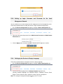
5.3.19. Setting up Network Information Display on TV Screen
Follow the procedure below to set up the receiver’s network information display:
1. Go to the Network Settings tab page by clicking the Network Settings tab.
2.
To enable/disable the Show network information on TV screen feature, go to the
Show network information on TV screen line, and set the feature to Enable or
Disable.
Note: By default, this feature is disabled. In this case, the network information is not displayed.
3. Click the Apply button, and then click OK on the pop-up message box to confirm.
After the network information display is enabled, network information is shown on the TV
screen.
46
5.3.20. Setting up Autonomous Group Owner (AGO)
The Autonomous Group Owner function (enabled) allows the receiver to be the group owner
during a p2p connection negotiation. In this case, the receiver can determine the channel for
communication.
In a Wi-Fi P2P group, the group owner operates as an access point and all other devices are
clients. After AGO is enabled, the receiver works as the P2P group owner.
To use the Managed Meetings (Intel® Pro WiDi) function, AGO must be enabled.
Follow the procedure below to set up the receiver’s AGO:
1. Go to the Network Settings tab page by clicking the Network Settings tab.
2. Set the Autonomous Group Owner (AGO) to Enable or Disable.
There are two options: Enable and Disable.
Enable: The receiver will become the group owner of the session. The communication
channel can be defined by the receiver. And the Managed Meetings feature is available.
47
Disable: The communication channel will be consistent with the source device, or be
determined through negotiation between the receiver and the connecting device. And
the Managed Meetings feature is not available.
Note: By default, AGO is enabled.
3. Click the Apply button, and then click OK on the pop-up message box to confirm.
4. The receiver reboots, and new settings take effect after the reboot.
5.3.21. Setting up Communication Channel
When AGO is enabled, you can define a channel for communication between the wireless
display receiver and the source device.
Follow the procedure below to set up the receiver’s communication channel:
1. Go to the Network Settings tab page by clicking the Network Settings tab.
2. Select a desired channel from the Channel Number drop-down box.
Channels from 1 to 11 belong to the 2.4 GHz band; and channels from 36 to 165 belong to
the 5 GHz band.
Availability of channels depends on the sales region.
You should select a channel based on your network environment. Generally, cleaner
48
channels (where less devices work) will provide better performance. You can use Wi-Fi
Analyzer to help you identify a clean channel.
3. Click the Apply button, and then click OK on the pop-up message box to confirm.
5.3.22. Setting up Group Owner Intent
When the AGO function is disabled, the Group Owner Intent function is available. The
Group Owner Intent function is used to determine which device (receiver or connecting
device) will be the group owner.
Follow the procedure below to set up the receiver’s group owner intent:
1. Go to the Features tab page by clicking the Features tab.
2. Select a desired value from the Group Owner Intent drop-down box.
Note: The larger the value is, the more likely the receiver becomes the group owner of the
P2P connection.
3. Click the Apply button, and then click OK on the pop-up message box to confirm.
4. The receiver reboots, and new settings take effect after the reboot.
49
5.3.23. Setting up P2P Network Parameters
When AGO is enabled, you can define network parameters for peer to peer connection,
including P2P Wireless Network Name (SSID), Password, IP address, subnet mask, DHCP
IP address range.
You should configure these parameters when you use the Managed Meetings function. When
source devices connect to the receiver, the receiver will assign IP addresses to these devices.
And these IP addresses are defined by the parameters discussed in this section.
Follow the procedure below to set up the receiver’s P2P network parameters:
1. Go to the Network Settings tab page by clicking the Network Settings tab.
2. Go to the Wireless Interface Settings section, and properly configure the network
parameters.
P2P Wireless Network Name (SSID) and P2P Wireless Network Password:
Reserved.
P2P IP Address: It is the IP address of the receiver in a peer to peer connection. This
IP address is displayed in the lower part of the Ready to connect screen. It is used to
access the local management server when AGO is enabled.
Note: The P2P IP Address must not in the range defined by P2P DHCP IP Start and
P2P DHCP IP End.
P2P Subnet Mask: It is the subnet mask for the network established in the peer to peer
connection.
P2P DHCP IP Start and P2P DHCP IP End: These two items define the range of IP
addresses assigned to the connected devices.
Note: These network parameters works when AGO is enabled.
3. Click the Apply button, and then click OK on the pop-up message box to confirm.
50
4. The receiver reboots, and new settings take effect after the reboot.
5.3.24. Setting up Wireless Network Parameters
When AGO is disabled, you can define wireless network parameters for accessing the
receiver’s local management web server, including wireless network name (SSID) and
password, IP address, subnet mask, and DHCP IP address range.
Follow the procedure below to set up the receiver’s wireless network parameters:
1. Go to the Network Settings tab page by clicking the Network Settings tab.
2. Go to the Wireless Interface Settings section, and properly configure the network
parameters.
Wireless Network Name (SSID) and Wireless Network Password: The SSID and
password for accessing the receiver’s wireless network. The SSID is displayed when
AGO is disabled.
51
Wireless IP Address: It is the IP address of the local management web server. This IP
address is displayed in the lower part of the Ready to connect screen. It is used to
access the local management server when AGO is disabled.
Note: The Wireless IP Address must not in the range defined by Wireless DHCP IP
Start and Wireless DHCP IP End.
Wireless Subnet Mask: It is the subnet mask of receiver’s network.
Wireless DHCP IP Start and Wireless DHCP IP End: These two items define the range
of IP addresses assigned to the connected devices.
Note: These network parameters works when AGO is disabled.
3. Click the Apply button, and then click OK on the pop-up message box to confirm.
4. The receiver reboots, and new settings take effect after the reboot.
5.3.25. Modifying the Receiver’s Wireless Network Name (SSID)
When AGO is disabled, you can modify the receiver’s wireless network name (SSID).
Follow the procedure below to modify the receiver’s SSID:
1. Go to the Network Settings tab page by clicking the Network Settings tab.
2.
Go to the Wireless Network Name (SSID) and Wireless Network Password section,
and type a new name in the Wireless Network Name (SSID) box and a new password
in Wireless Network Password box.
52
3.
Click the Apply button, and then click OK on the pop-up message box to confirm.
4.
The receiver reboots, and the new SSID takes effect after the reboot.
5.3.26. Setting up Broadcast Network Name
Follow the procedure below to set up the receiver’s Broadcast Network Name:
1. Go to the Network Settings tab page by clicking the Network Settings tab.
2.
To enable/disable the Broadcast Network Name feature, go to the Wireless Interface
Settings section, and set the Broadcast Network Name feature to Enable/Disable.
Note: By default, the Broadcast Network Name is disabled. The receiver’s SSID is not
53
broadcasted when the Broadcast Network Name function is disabled. In this situation you
can connect to the SSID manually. Refer to Section 5.1.2.2. When SSID Broadcast is
Disabled for detail.
3. Click the Apply button, and then click OK on the pop-up message box to confirm.
4.
The receiver reboots, and the new setting takes effect after the reboot.
5.3.27. Setting up Wireless Connection Properties
The receiver can wirelessly connect to your network through the ScreenBeam CMS WLAN
Adapter. We need to set up the wireless connection parameters before starting the
connection.
Follow the procedure below to set up the receiver’s wireless connection properties:
1. Go to the Remote Management tab page by clicking the Remote Management tab.
2.
Go to the Wireless Connection Property Settings section, and configure the
parameters according to specific requirements.
Network Name: The SSID of the wireless router (AP).
Security Type: Select a security type, the one you have selected on your wireless router.
Available security types are Open, Shared, WPA-PSK[TKIP], WPA2-PSK[AES], WPAPSK[TKIP]+WPA2-PSK[AES], PEAP/MSCHAPV2, and EAP-TLS.
Status: It displays the connection states.
When Shared, WPA-PSK[TKIP], WPA2-PSK[AES], or WPA-PSK[TKIP]+WPA2-PSK[AES]
is selected,
54
User Name: Not used.
Password: The pre-shared password for the wireless SSID.
When PEAP/MSCHAPV2 is selected,
User Name: This is for authentication through a RADIUS server. It is RADIUS account
User Name.
Password: It is RADIUS account password.
When EAP-TLS is selected, the following items are available:
User Name: It is the User Principal Name or RADIUS Identity (if necessary).
Note: The User Name supports these characters: a-z, A-Z, 0-9, @, ., and _.
Password: It is the password of the Private Key.
System Date & Time: It is used to set date and time for the receiver. You should set the
date and time according to the validity period of the certificates.
CA Certificate: It is the root certificate. Click the Browse button to browse and add the
certificate.
User Certificate: It is the user certificate. Click the Browse button to browse and add
the certificate.
Private Key: It is the user’s private key. Click the Browse button to browse and add the
certificate.
Validity Period: It displays the effective period of the certificates.
Note:
Currently, only certificates in the “.pem” format are supported, and the certificates must
be generated using the “DER encoded binary X.509” method.
The length of the certificate file name must not exceed 64 bytes, and the file size must
be less than 100 KB.
All the three certificates are required for authentication.
You must select the right certificate file for each type of certificate.
3. Click the Connect button, and then the adapter will connect to the wireless router (AP).
Note:
Connect the CMS WLAN Adapter to your network when the receiver is in Ready to
Connect state.
The CMS WLAN Adapter may take some time to connect to your network, depending
on your network environment.
5.3.28. Setting up the Receiver’s IP Address
Follow the procedure below to set up the receiver’s IP address:
1. Go to the Remote Management tab page by clicking the Remote Management tab.
55
2.
Go to the TCP/IP Setting section, and set the IP Assignment to Auto or Static.
Auto: The receiver will be assigned an IP address by the DHCP server.
Static: You can define the IP address, subnet mask, and default gateway for the receiver.
If you select Static, you can define a DNS server.
3.
Click the Apply button, and then click OK on the pop-up message box to confirm.
5.3.29. Specifying a DNS Server for the Receiver
Follow the procedure below to specify a DNS server for the receiver:
1. Go to the Remote Management tab page by clicking the Remote Management tab.
2.
Go to the TCP/IP Setting section, and set the DNS Assignment to Auto or Static.
Auto: The receiver will be assigned a DNS server automatically.
Static: You can define a DNS server for the receiver. When you select Static, you must
define a DNS server.
56
3.
Click the Apply button, and then click OK on the pop-up message box to confirm.
5.3.30. Specifying the ScreenBeam CMS for the Receiver
Follow the procedure below to specify a management server for the receiver:
1. Go to the Remote Management tab page by clicking the Remote Management tab.
2.
Go to the Central Management System Setting section, and define the CMS Host and
the CMS Port.
CMS Host: It is the IP address or the FQDN/hostname/domain name/alias name (if you
have properly configured the DNS server and the DHCP server) of the server that hosts
the ScreenBeam CMS. It supports a domain with six labels at most.
Note: We recommend using the DNS setting.
CMS Port: It is the communication port of the ScreenBeam CMS.
3.
Click the Apply button, and then click OK on the pop-up message box to confirm.
57
5.3.31. Rebooting the Receiver
Follow the procedure below to reboot the receiver:
1. Go to the Maintenance tab page by clicking the Maintenance tab.
2. Click the Yes button next to “Reboot Receiver”.
3. Click OK on the pop-up message box to confirm.
5.3.32. Resetting the Receiver to Default
Follow the procedure below to reset the receiver to the default settings:
1. Go to the Maintenance tab page by clicking the Maintenance tab.
2. Click the Yes button next to “Reset Settings to Factory”.
58
3. Click OK on the pop-up message box to confirm.
4. The receiver reboots, and the receiver is reset to factory defaults after the reboot.
Note: You can also reset your receiver to default by pressing the "Reset" button. Follow the
procedure below to restore the Receiver's default factory settings:
1. Power on the Receiver, and wait until the "Ready to connect" screen appears.
2. Hold down the Receiver's "Reset" button with a pin.
3. When the "Reset to Default" screen appears on the HDTV, release the "Reset" button.
The Receiver reboots, and it will be running with its default settings.
5.4. Upgrading the Receiver
ScreenBeam Pro supports firmware upgrade. And Actiontec’s ScreenBeam team will
constantly improve the receiver’s performance with new firmware.
Follow the procedure below to upgrade your receiver:
1. Log into ScreenBeam Pro’s web server, and go to the Features tab page by clicking
the Features tab.
2. Set the USB Local Access feature to Only allow firmware update, or Enable.
3. Go to the Firmware Upgrade tab page by clicking the Firmware Upgrade tab.
59
4. On the Firmware Upgrade tab page, you can check the current firmware version in the
Firmware Version section and upgrade the receiver.
5. Select Enable in the Firmware Update box.
6. Download the latest firmware from Actiontec’s website:
http://www.actiontec.com/sbupdate.
Note: You should disconnect from the receiver’s SSID and connect to a router’s SSID
before downloading firmware.
7. Extract the zip file. You will find one "autorun" folder and one "install.img" file in the
extracted file folder.
8. Copy the "autorun" folder and the "install.img" file to the root directory of a USB flash
drive.
Note: Do not use a portable hard drive. You should use a FAT/FAT32 formatted USB
flash drive only.
9. Make sure the "Ready To connect" screen appears on your TV.
Note: You must disconnect your device (laptop, ultrabook, smartphone or tablet) from
the receiver before upgrading your receiver.
10. Plug the USB flash drive into the USB port on ScreenBeam Pro.
11. The Receiver starts to update its firmware automatically. Firmware upgrade status
messages appear on your TV.
Warning! Do not power off the Receiver or remove the USB flash drive while the
upgrade is in progress. Otherwise, firmware upgrade fails.
12. The Receiver reboots after firmware update completes.
13. You may now remove the USB flash drive when you see the "Ready to connect" screen
again.
60
Part VI. FAQs and Troubleshooting
This chapter describes frequently asked questions (FAQs), and answers to those questions.
Also included are some problems you may encounter using the receiver, and possible
solutions to those problems.
6.1. FAQ
(Q) What is AGO mode?
(A) AGO stands for Autonomous Group Owner. By default, this mode is enabled for
ScreenBeam Pro Business Edition receiver and allows IT to manage the Miracast (P2P)
operating channel. Conventional Miracast receiver such as ScreenBeam Mini2, Pro, and
Education do not offer this feature.
(Q) What are the recommended system requirements for ScreenBeam Pro Business Edition
receiver.
(A) In addition to the systems listed in the compatibility section above, we highly recommend
the system's wireless network adapter and driver to support DCM.
(Q) What is DCM?
(A) DCM stands for Different Channel Mode. This feature belongs to the wireless network
adapter and its driver. It enables the system's wireless to simultaneously operate on different
wireless channels, and supports applications such as Wi-Fi infrastructure and Wi-Fi direct.
(Q) My TV/Projector is not displaying anything or the display is switched to another input
instead. I had previously seen the "Ready to connect" screen.
(A) By default, the HDMI port power management is configured to turn off after 3 minutes to
protect the projector's bulb lifetime. Connect to management webpage and configure the
setting to either Always On or Screensaver.
(Q) After connecting, why am I only seeing my desktop background with no icons on the
TV/Projector display?
(A) Your Windows system might automatically project in Extended mode. You can configure
it to project in Duplicate mode. Press (Windows icon + P) buttons, and select the projection
mode.
(Q) Do I need to have Intel Pro WiDi or WiDi to connect to ScreenBeam Business receiver?
(A) No. You can connect to ScreenBeam Business receiver from Miracast (Win8.1) device
as a participant.
(Q) I cannot start a Managed meetings session with my Intel WiDi* or Miracast system.
(A) To initiate a Managed meetings session, the system must be an Intel vPro* and have Intel
61
Pro WiDi* application (6.x.x.x).
(Q) Is there anything I could do to improve the A/V performance?
(A) You could set the P2P operating channel to a cleaner frequency. By default, the
Autonamous Group Owner is set to channel 11 on 2.4GHz band. You could use a Wi-Fi
scanner program and scan for an open channel, and select that channel on the AGO setting.
(Q) Where can I find the receiver name to connect to if someone else is already connected
and using the TV/Projector display?
(A) We recommend to create a sign with the receiver's name for participants to connect to.
(Q) How do I log in to the Local Management web GUI?
(A) From either an Intel WiDi/Miracast system, connect to the Receiver using the Miracast
connection. Open a web browser and enter in http://192.168.16.1. The default credential
Login: Administrator and Password: WiDi
(Q) Where can I get the user manual for Intel Pro WiDi application and Managed meetings?
(A) This URL http://www.actiontec.com/prowidi will redirect you to Intel's webpage. There,
you can find the instructions and more details.
(Q) Where can I obtain the latest Intel graphics driver, Intel wireless driver, and Intel WiDi
application?
(A) https://downloadcenter.intel.com
(Q) How many participants can connect to ScreenBeam Pro Business Edition receiver during
Managed meetings session?
(A) Up to 16 participants.
(Q) What's Actiontec CMS?
(A) CMS is Actiontec's ScreenBeam Central Management System software. It enables IT to
remotely configure, monitor, and manage multiple ScreenBeam receivers from a central
location. To learn more, visit http://www.actiontec.com/sbcms.
(Q) How does ScreenBeam receiver connect to the network for management?
(A) ScreenBeam receiver can connect to the network by either wired or wireless. Upon
purchasing CMS, you can select the USB-to-Wireless or USB-to-Ethernet solution.
(Q) Is 4096 certs supported in EAP-TLS wireless authentication?
(A) Currently it's not supported.
(Q) I am trying to connect to the SSID "DIRECT-xyABCDEF", but failed. Why?
(A) This SSID is reserved. To log into the local web management, you should connect your
device to the ScreenBeam receiver first, and then access the URL: http://192.168.16.1
(default).
62
6.2. Troubleshooting
In some instances Windows 8.1 Miracast does not have the "Add a wireless display"
option, or Intel WiDi application may have problem to connect if there's a VPN software
running on the system. If this occurs, please disable your VPN temporarily to confirm
and consult with the VPN vendor on how to allow Miracast/WiDi. The following known
programs that affect Miracast and Intel WiDi are:
Cisco VPN client
WebEx
Juniper VPN
ReadyNAS
Virtual box
Participant device(s) with legacy wireless network adapter may experience the following
issues during the Miracast/WiDi session with ScreenBeam receiver: 1) intermittent
disconnection and 2) performance degradation. Legacy wireless adapters are
considered systems without the following qualified adapters;
Intel Dual Band Wireless-AC 3160*
Intel Dual Band Wireless-AC 7260*
Intel Dual Band Wireless-N 7260*
Intel Dual Band Wireless-AC 7265*
Intel Dual Band Wireless-N 7265*
Resolution: Check PC OEM or wireless network adapter's manufacturer for the latest
driver updates. If the problem persists, disconnect Wi-Fi connection from Access Point
and reconnect to ScreenBeam receiver.
Connecting to an access point with an active WiDi session can result in dropping the
WiDi connection.
Resolution: Reconnect to WiDi receiver or connect to the Access point first before
starting a WiDi session
In some instances you may not be able to connect to ScreenBeam receiver after
installing McAfee or Norton antivirus software. This is a limitation to Intel WiDi app.
Resolution: Make sure you have the latest updates and if the issue persist, add WiDi
to the antivirus software approved white list of applications.
Intel WiDi user interface shows status as "Connecting" and TV displays status as
"Connected" permanently during a connect/disconnect scenario in which the User
attempts to cancel during WiFi Protected Setup and clicks connect again.
Resolution: Click the cancel button and wait about 40 seconds for the receiver to return
to the ready for connection state and start the pairing process again.
63
In some instances video playback is not smooth when the system is running in battery
mode.
Resolution: Plug in AC power.
In some instances a 2nd PC attempting to pair to a ScreenBeam receiver that is already
in exclusive mode/use by another user is presented a PIN window but no PIN is
displayed on the ScreenBeam receiver when they should receive a message telling them
the receiver is in exclusive use.
Resolution: Don't connect to receiver if it's in exclusive mode.
In some instances of opening a word processing program such as Notepad and the user
scales the image the text can have choppy edges if the font size is small.
Resolution: Use larger font size or use a scaling size that doesn’t impact the image
quality.
In some instances random audio glitches are seen when the source system has an
active VPN session running.
Resolution: Stop the VPN session.
In some instances (random) a Failed to Pair message is display after PIN message, then
the connection is established successfully.
Resolution: None.
Default resolution for Intel Dual Band Wireless-AC 3160* is allowing 1920x1080
resolution when it should be limited to 1366x768.
Resolution: None.
64