1
Central Management System
Deployment Guide
Version 1.2.15
Document and Software Copyrights
This Actiontec Document and all software offered through or used on this Actiontec Document are our property or the
property of our suppliers, sponsors, licensors or affiliates (collectively, "Business Partners"), and are protected by United
States and international copyright law, trademark law, and trade secret law, as well as other laws, rules and regulations.
We own a copyright in this Actiontec Document and in the selection, coordination and arrangement of the content
available through this Actiontec Document. Except as expressly provided herein, neither we nor our Business Partners
grant any rights to you under any patents, copyrights, trademarks or trade secret information. Accordingly, unauthorized
use of this Actiontec Document or any content available on this Actiontec Document may violate patent laws, copyright
laws, trademark laws, trade secret laws, and laws pertaining to privacy and publicity rights or other laws or regulations.
Copyright © 2015 Actiontec Electronics, Inc. All Rights Reserved. Actiontec, ScreenBeam, the Actiontec logo, and the
ScreenBeam logo and all page headers, custom graphics and button icons are the service marks, trademarks, and/or
trade dress of Actiontec ("Trademarks"). All other service marks, trademarks, product names and company names or
logos displayed in this Actiontec Document are the property of their respective owners. You may not use, copy,
reproduce, republish, upload, post, transmit, distribute or modify any of the Trademarks in any way, including in
advertising or publicity pertaining to distribution of materials on this Actiontec Document, without our prior written
consent.
Version Information
ScreenBeam Central Management System User Manual
Version 1.2.15
Date: Apr 21, 2015
Company Information
Actiontec Electronics, Inc.
760 North Mary Ave.
Sunnyvale, California 94085
(408) 752-7700
(408) 541-9003 fax
www.actiontec.com
ScreenBeam Central Management System
Page 2
Contents
Section 1 Overview and Setup ....................................................................................................................................6
1.1
Introduction .............................................................................................................................................................................. 6
1.2
Minimum System Requirements ............................................................................................................................................... 7
1.3
Preparing the System ................................................................................................................................................................ 8
1.4
Installing the Software ............................................................................................................................................................ 10
1.5
Getting to Know the User Interface ........................................................................................................................................ 14
1.5.1
Menu Bar............................................................................................................................................................................. 15
1.5.2
Action Bar ............................................................................................................................................................................ 15
1.5.3
Receiver List ........................................................................................................................................................................ 15
1.5.4
Group Pane ......................................................................................................................................................................... 15
1.5.5
Receiver Pane ...................................................................................................................................................................... 15
1.5.6
Status Bar ............................................................................................................................................................................ 15
1.5.7
Selecting Receivers.............................................................................................................................................................. 15
1.6
Customizing the Column Header of the Receiver Pane .......................................................................................................... 16
1.6.1
Hiding a Column .................................................................................................................................................................. 16
1.6.2
Hiding or Showing Columns ................................................................................................................................................ 17
1.6.3
Arrange Sequence for Active Columns ................................................................................................................................ 19
1.6.4
Adjusting Size for a Column ................................................................................................................................................ 20
1.6.5
Adjusting Size for all Columns ............................................................................................................................................. 21
1.7
Setting up the Close Button Behavior ..................................................................................................................................... 22
1.8
Updating the CMS Software ....................................................................................................................... 错误!未定义书签。
1.9
Checking the CMS Version ...................................................................................................................................................... 23
1.10
Exiting the CMS Software ........................................................................................................................................................ 24
Section 2 Setup the Receivers ................................................................................................................................... 26
2.1
Hardware Connection ............................................................................................................................................................. 26
2.1.1
Wired Connection ............................................................................................................................................................... 26
2.1.2
Wireless Connection ........................................................................................................................................................... 26
2.2
Network Topology ................................................................................................................................................................... 28
2.3
Configuring a Receiver’s Network Interface ............................................................................................................................ 29
Section 3 Discovering Receivers ................................................................................................................................ 31
3.1
Setup Port Forwarding ............................................................................................................................................................ 31
3.2
DNS Discovery ......................................................................................................................................................................... 32
3.2.1
Configure DNS and DHCP Servers ....................................................................................................................................... 32
3.2.2
Deploy the ScreenBeam Receivers ..................................................................................................................................... 35
3.3
UPnP Discovery ....................................................................................................................................................................... 36
ScreenBeam Central Management System
Page 3
3.3.1
Turning on UPnP in Windows ............................................................................................................................................. 36
3.3.2
Turning on UPnP in the Router ........................................................................................................................................... 38
3.3.3
Discover Receivers Using UPnP ........................................................................................................................................... 38
3.4
Discover Receivers Using a USB Drive ..................................................................................................................................... 40
3.5
Deleting Offline Receivers ....................................................................................................................................................... 42
3.6
Locating Your Receiver ............................................................................................................................................................ 43
Section 4 Group Management .................................................................................................................................. 45
4.1
Create a Group ........................................................................................................................................................................ 45
4.2
Add Receivers to a Group ........................................................................................................................................................ 48
4.3
Release Receivers from a Group ............................................................................................................................................. 50
4.4
Modify a Group ....................................................................................................................................................................... 52
4.5
Delete a Group ........................................................................................................................................................................ 53
Section 5 Receiver Settings ....................................................................................................................................... 56
5.1
Configure a Single Receiver ..................................................................................................................................................... 56
5.2
Configure Multiple Receivers .................................................................................................................................................. 57
5.3
Configuring Receivers using a USB Flash Drive ....................................................................................................................... 60
5.4
Setting the Screen Saver Image............................................................................................................................................... 61
5.4.1
Screen Saver Image Requirements ..................................................................................................................................... 61
5.4.2
Setting the Screensaver Image............................................................................................................................................ 61
5.5
Setting a Background Image .................................................................................................................................................... 64
5.5.1
Background Image Requirements ....................................................................................................................................... 64
5.5.2
Setting a Background Image ............................................................................................................................................... 64
Section 6 Updating Receiver Firmware ..................................................................................................................... 68
6.1
Firmware Update Server ......................................................................................................................................................... 68
6.2
Update the Receiver Firmware ............................................................................................................................................... 68
Section 7 Receiver Logs ............................................................................................................................................ 72
7.1
Enable Receiver Log Upload .................................................................................................................................................... 72
7.1.1
Logged Events ..................................................................................................................................................................... 72
7.1.2
Enabling Receiver Logging ................................................................................................................................................... 72
7.2
Viewing Receiver Logs ............................................................................................................................................................. 78
7.3
Log Management .................................................................................................................................................................... 79
Section 8 CMS Server Settings .................................................................................................................................. 81
8.1
Switch Receiver to a different CMS Server.............................................................................................................................. 81
8.2
Modify CMS Server Settings .................................................................................................................................................... 84
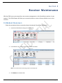
Section 9 Receiver Maintenance ............................................................................................................................... 86
9.1
Reboot Receivers..................................................................................................................................................................... 86
9.2
Restore Receiver Factory Defaults .......................................................................................................................................... 88
ScreenBeam Central Management System
Page 4
9.3
Receiver Description ............................................................................................................................................................... 91
Section 10 Troubleshooting ...................................................................................................................................... 93
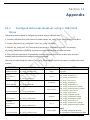
Section 11 Appendix ................................................................................................................................................ 95
11.1
Configure Actiontec Receiver using a USB Flash Drive ............................................................................................................ 95
ScreenBeam Central Management System
Page 5
Section 1
Over view and Setup
Congratulations on purchasing your ScreenBeam™ Central Management System (CMS). With this solution
Actiontec Electronics, Inc. provides a full set of tools to simplify the configuration and management of your
ScreenBeam receivers. We recommend reading through this section to familiarize yourself with the features
and benefits the ScreenBeam™ Central Management System has to offer.
1.1 Introduction
Actiontec’s ScreenBeam™ Central Management System (CMS) is a full-featured software utility to
remotely configure and manage a group of ScreenBeam wireless display receivers. After the initial
setup, the CMS utility will communicate over your network to each ScreenBeam receiver, allowing for
full control of each unit. This CMS utility will ease the burden of having to configure each ScreenBeam
receiver in your network individually.
DNS Discovery: Use your corporate DNS to automatically have each ScreenBeam Receiver connect to
your ScreenBeam CMS server.
UPnP Discovery: Discover all your local network receivers automatically by enabling UPnP. CMS will
automatically populate the Receiver list with all discovered ScreenBeam receivers in your network.
USB Configuration Tool: Easily generate the necessary configuration files to define receiver IP
parameters and the CMS server to connect to, then write to a flash drive. Plug the drive into the
ScreenBeam receiver and it will automatically configure itself to the values you set.
CMS Handoff: Seamlessly switch which CMS PC a receiver, or set of receivers, will connect to.
Remote Settings: Make parameters changes for one-to-many receivers from the CMS server remotely.
All the settings that are available for each receiver locally are also available through the CMS server.
Firmware Update: Update firmware for receivers in batch using the ScreenBeam CMS server.
Grouping: Organize receivers into group sets allowing you to easily select a particular set of receivers
for configuration and management.
Logging: Save receiver logs locally on the CMS server or to a remote FTP server. Logs can be updated
on a schedule that you define.
Reboot/Restore: Remotely reboot receivers or set them back to factory default.
ScreenBeam Central Management System
Page 6
1.2 Minimum System Requirements
For PC running the ScreenBeam CMS software:
Microsoft Windows 7, 8, or 8.1
Core i3 or equivalent processor
4 gigabyte RAM
200 MB of free HDD space
Stable 100/1000 network connection
Open the following ports to the PC running ScreenBeam CMS:
TCP 7237: To communicate with the receivers
TCP 7238: For uploading receiver logs to the CMS server
Note: Both ports are customizable. These are the default values.
Companion servers:
Web Server (for receiver firmware downloads, screensaver update, and background update)
Internal corporate DNS Server (optional, but strongly recommended)
FTP Server (optional)
ScreenBeam Receivers:
ScreenBeam Pro – Business Edition
ScreenBeam Pro –Education Edition 2
Firmware: 2.10.7.0 (or higher)
Firmware: 2.9.17.0 (or higher)
Actiontec USB-to-Ethernet adapter (SBETH100) or USB-to-Wireless adapter (SBT100U), for each ScreenBeam
receiver
ScreenBeam Central Management System
Page 7
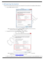
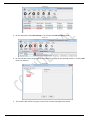
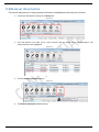
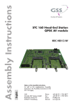
1.3 Preparing the System
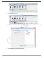
Follow the instructions below to prepare your selected PC for use with the ScreenBeam CMS software.
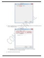
1. Assign a fixed IP address for the PC.
Figure 1.3-1
Note: A fixed IP address is required. Using a dynamic IP address may cause lost connectivity
between the CMS server and the receivers.
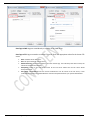
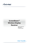
2. If applicable, enter the corporate DNS address for your network.
Figure 1.3-2
Note: A corporate DNS server is required if you will be discovering receivers using the DNS
method. Refer to Section 3.2 – DNS Discovery for details.
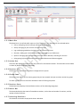
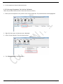
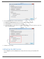
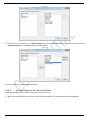
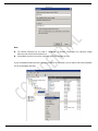
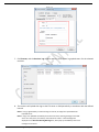
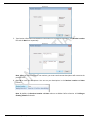
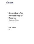
3. Make sure SSDP Discovery service is running. Start the Services Manager by typing services.msc from the
ScreenBeam Central Management System
Page 8
Run or Search bar.
Figure 1.3-3
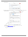
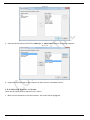
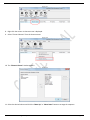
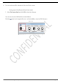
4. Scroll down to SSDP Discovery and double click it. Set the Startup type to Automatic and start it if the
service is not running.
Figure 1.3-4
Note: Enabling this service is only required if using the UPnP method for receiver discovery.
Refer to Section 3.3 – UPnP Discovery for details.
ScreenBeam Central Management System
Page 9
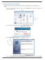
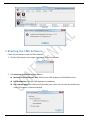
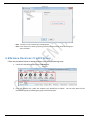
1.4 Installing the Software
Follow the instructions below to install the ScreenBeam Central Management System application to
your PC.
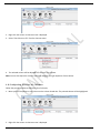
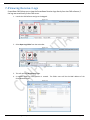
1. Insert the installation media into your PC. Double-click the setup.exe file to launch the setup program if it
doesn’t automatically run.
Figure 1.4-1
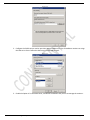
2. You may see the following User Account Control message. Select Yes to continue.
Figure 1.4-2
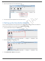
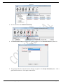
3. The setup wizard Welcome screen appears. Select Next to continue.
Figure 1.4-3
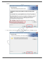
4. Click the I accept the terms in the license agreement checkbox to accept the terms and click Next to
ScreenBeam Central Management System
Page 10
continue.
Figure 1.4-4
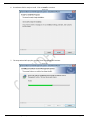
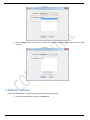
5. Enter a location to install the program, or accept the default location. Click Next to continue.
Figure 1.4-5
ScreenBeam Central Management System
Page 11
6. ScreenBeam CMS is ready to install. Click on Install to continue.
Figure 1.4-6
7. The setup wizard will copy the program file to the appropriate locations.
Figure 1.4-7
ScreenBeam Central Management System
Page 12
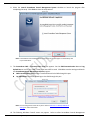
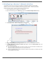
8. Select the Launch ScreenBeam Central Management System checkbox to launch the program after
completing the setup. Click Finish to close the setup wizard.
Figure 1.4-8
Note: A ScreenBeam Central Management System shortcut will also appear on the Desktop and
in your Start Menu.
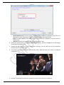
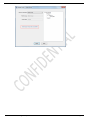
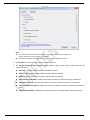
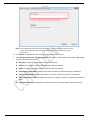
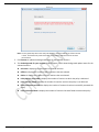
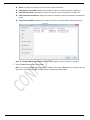
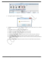
9. The ScreenBeam CMS – Communication Ports box appears. Set the CMS Communication Port and Log
Upload Port to use for your CMS. These ports must NOT be used. Click OK to save the settings and launch
the ScreenBeam Central Management System program.
CMS Communication Port: Receivers communicate with the CMS through this port.
Log Upload Port: Receivers upload logs to the CMS through this port.
Figure 1.4-9
Note: You can change these values at any time. Refer to Section 8.2 – Modify CMS Server
Settings for more information.
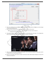
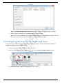
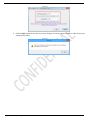
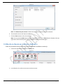
10. The following Windows Firewall screen may appear. Select to allow ScreenBeam Central Management
ScreenBeam Central Management System
Page 13
System through the firewall. Click Allow access to continue.
Figure 1.4-10
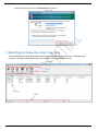
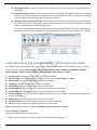
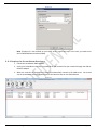
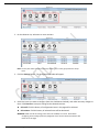
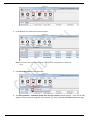
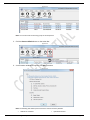
1.5 Getting to Know the User Interfa ce
You should familiarize yourselves with the server interface before using the server to manage your
receivers. The figure below shows the main interface of the Management Server.
Figure 1.5-1
ScreenBeam Central Management System
Page 14
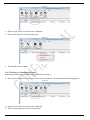
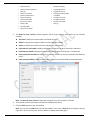
Figure 1.5-2
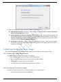
1.5.1 Menu Bar
The Menu Bar is a list of tabs which open up a list of functions in the Action Bar for the selected option.
Policy: configuring receiver settings, maintenance, and logging
Group: managing all your receivers into custom groups
Log: enabling log uploads to the local server or a remote FTP server
Discovery: adding your receivers and configuring settings for your CMS server
Options: managing logs and customizing the Close button behavior; searching for receivers
Help: getting help and information about the CMS software and software upgrade
1.5.2 Action Bar
The Action Bar displays the functions you can perform for the selected receivers. The Action Bar can be hidden
or shown by double-clicking the tab header.
1.5.3 Receiver List
The Receiver List displays all the receivers configured in the system.
1.5.4 Group Pane
The Group Pane displays all the custom groups that you have created. And you can select receivers by group.
To select a group, you must check the checkbox to the left of that group name.
1.5.5 Receiver Pane
The Receiver Pane displays the ScreenBeam receivers of the selected group/groups.
1.5.6 Status Bar
The Status Bar displays the status of ScreenBeam receivers, such as the total number of receivers, and the
number of online receivers.
1.5.7 Selecting Receivers
The selection conventions comply with those in Windows.
ScreenBeam Central Management System
Page 15
Selecting a receiver: To select a receiver, click a receiver entry on the receiver list. The selected receiver is
highlighted.
Selecting multiple receivers: To select multiple receivers: hold down the “Ctrl” key and click the desired
receivers. The selected receivers are highlighted. You can also deselect a receiver (or receivers) by holding
down the “Ctrl” key and then clicking the receiver (or receivers).
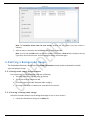
Selecting receivers in the Group Pane: To select all receivers in a group, check the checkbox of that group.
All selected receivers are highlighted. To deselect the receivers in a group, clear the check mark. The two
selection methods discussed above also apply here.
You must note that clicking the group name (the box not checked) will display all receivers of this group in
the receiver list, but they are not selected. In the example below, receiver “Actiontec 7A26” is not selected.
Figure 1.5-3
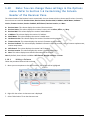
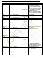
1.6 Customizing the Column Header of the Receiver Pane
The column header of the Receiver Pane is customizable. You can choose to hide or show a specific column. Currently,
these columns are available: Receiver Name, Receiver Status, Receiver MAC, IP Address, Model Name, Hardware
Version, Firmware Version, Receiver Feedback, Wifi Channel, Receiver Location, and Note.
Receiver Name: This column displays the receiver’s Receiver Name.
Receiver Status: This column displays the receiver’s status, such as Online, Offline, and Busy.
Receiver MAC: This column displays the receiver’s MAC address.
IP Address: This column displays the receiver’s IP address.
Model Name: This column displays the receiver’s model name.
Hardware Version: This column displays the receiver’s hardware version number.
Firmware Version: This column displays the receiver’s firmware version number.
Receiver Feedback: This column displays feedback information from the receiver, such as firmware update status,
receiver setup status.
Wifi Channel: This column displays the receiver’s Wi-Fi channel.
Receiver Location: This column displays the receiver’s location information.
Note: This column displays user-defined information for the receiver.
Note: By default, these columns are hidden: Wifi Channel, Receiver Location, and Note.
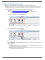
1.6.1 Hiding a Column
Follow the procedure below to hide a column,
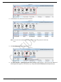
1. Move your mouse pointer to the desire column. The column will be highlighted.
ScreenBeam Central Management System
Page 16
Figure 1.6-1
2. Right-click the column. A shortcut menu is displayed.
3. Select “Hide Column” from the shortcut menu.
Figure 1.6-2
4. The selected column is hidden.
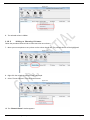
1.6.2 Hiding or Showing Columns
Follow the procedure below to hide or show more than one columns,
1. Move your mouse pointer to any column on the column header bar. The pointed column will be highlighted.
Figure 1.6-3
2. Right-click the column. A shortcut menu is displayed.
3. Select “Choose Columns” from the shortcut menu.
ScreenBeam Central Management System
Page 17
Figure 1.6-4
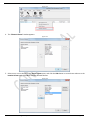
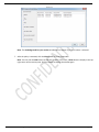
4. The “Choose Columns” window appears.
Figure 1.6-5
5. Select one or more columns in the Active Column pane, and click the Hide button to move these columns to the
Inactive Column pane. Click OK to hide the selected columns.
Figure 1.6-6
ScreenBeam Central Management System
Page 18
6. Do the opposite to show the desired columns.
1.6.3 Arrange Sequence for Active Columns
Follow the procedure below to hide or show more than one columns,
1. Move your mouse pointer to any column on the column header bar. The pointed column will be highlighted.
Figure 1.6-7
2. Right-click the column. A shortcut menu is displayed.
3. Select “Choose Columns” from the shortcut menu.
Figure 1.6-8
4. The “Choose Columns” window appears.
ScreenBeam Central Management System
Page 19
Figure 1.6-9
5. Select the desired column and click the “Move Up” or “Move Down” button to arrange the sequence.
Figure 1.6-10
6. Repeat the step above the arrange sequence for other columns. Click OK to confirm.
1.6.4 Adjusting Size for a Column
Follow the procedure below to adjust size for a column,
1. Move your mouse pointer to the desire column. The column will be highlighted.
ScreenBeam Central Management System
Page 20
Figure 1.6-11
2. Right-click the column. A shortcut menu is displayed.
3. Select “Size Column to Fit” from the shortcut menu.
Figure 1.6-12
4. The selected column will be adjusted to fit the size of its content.
Note: You can also adjust the size of a column by dragging the right separator of that column.
1.6.5 Adjusting Size for all Columns
Follow the procedure below to adjust size for all columns,
1. Move your mouse pointer to any column on the column header bar. The pointed column will be highlighted.
Figure 1.6-13
2. Right-click the column. A shortcut menu is displayed.
ScreenBeam Central Management System
Page 21
3. Select “Size All Columns to Fit” from the shortcut menu.
Figure 1.6-14
4. The active columns will be adjusted to fit the size of their content.
1.7 Setting up the Close Button Behavior
You can customize the behavior of the Close button here. By clicking the Close button, the CMS’s main window will
minimize to the notification area or the CMS is closed, depending on your choice.
1. Launch the CMS software and go to the Options tab.
Figure 1.7-1
2. Select the Options button from the Action Bar.
Figure 1.7-2
3. The ScreenBeam CMS – Options window appears.
ScreenBeam Central Management System
Page 22
Figure 1.7-3
4. Go to the Close Button section, and select a desired option.
Minimize to the Notification Area: Minimize the CMS window to the Notification Area.
Exit immediately: Close the CMS application immediately.
Don’t ask me again: The CMS software will remember your choice and not show this window any more if this
option is selected (checked).
Figure 1.7-4
5. Click OK to save your settings.
1.8 Checking the CMS Version
Go to the Help tab, and click the About button to display information about your ScreenBeam CMS
software.
ScreenBeam Central Management System
Page 23
Figure 1.8-1
Figure 1.8-2
1.9 Exiting the CMS Software
Follow the procedure to close the CMS software:
1. Click the Close button in the upper right corner of the CMS window.
Figure 1.9-1
2. The Select your preference window appears.
Minimize to the Notification Area: Minimize the CMS window to the Notification Area.
Exit immediately: Close the CMS application immediately.
Don’t ask me again: The software will remember your choice and not show this window any
more if this option is selected (checked).
Figure 1.9-2
ScreenBeam Central Management System
Page 24
1.10
Note: You can change these settings in the Options
menu. Refer to Section 1.6 Customizing the Column
Header of the Receiver Pane
The column header of the Receiver Pane is customizable. You can choose to hide or show a specific column. Currently,
these columns are available: Receiver Name, Receiver Status, Receiver MAC, IP Address, Model Name, Hardware
Version, Firmware Version, Receiver Feedback, Wifi Channel, Receiver Location, and Note.
Receiver Name: This column displays the receiver’s Receiver Name.
Receiver Status: This column displays the receiver’s status, such as Online, Offline, and Busy.
Receiver MAC: This column displays the receiver’s MAC address.
IP Address: This column displays the receiver’s IP address.
Model Name: This column displays the receiver’s model name.
Hardware Version: This column displays the receiver’s hardware version number.
Firmware Version: This column displays the receiver’s firmware version number.
Receiver Feedback: This column displays feedback information from the receiver, such as firmware update status,
receiver setup status.
Wifi Channel: This column displays the receiver’s Wi-Fi channel.
Receiver Location: This column displays the receiver’s location information.
Note: This column displays user-defined information for the receiver.
Note: By default, these columns are hidden: Wifi Channel, Receiver Location, and Note.
1.10.1
Hiding a Column
Follow the procedure below to hide a column,
5. Move your mouse pointer to the desire column. The column will be highlighted.
Figure 1.6-1
6. Right-click the column. A shortcut menu is displayed.
7. Select “Hide Column” from the shortcut menu.
ScreenBeam Central Management System
Page 25
Figure 1.6-2
8. The selected column is hidden.
1.10.2
Hiding or Showing Columns
Follow the procedure below to hide or show more than one columns,
7. Move your mouse pointer to any column on the column header bar. The pointed column will be highlighted.
Figure 1.6-3
8. Right-click the column. A shortcut menu is displayed.
9. Select “Choose Columns” from the shortcut menu.
Figure 1.6-4
10. The “Choose Columns” window appears.
ScreenBeam Central Management System
Page 26
Figure 1.6-5
11. Select one or more columns in the Active Column pane, and click the Hide button to move these columns to the
Inactive Column pane. Click OK to hide the selected columns.
Figure 1.6-6
12. Do the opposite to show the desired columns.
1.10.3
Arrange Sequence for Active Columns
Follow the procedure below to hide or show more than one columns,
7. Move your mouse pointer to any column on the column header bar. The pointed column will be highlighted.
ScreenBeam Central Management System
Page 27
Figure 1.6-7
8. Right-click the column. A shortcut menu is displayed.
9. Select “Choose Columns” from the shortcut menu.
Figure 1.6-8
10. The “Choose Columns” window appears.
Figure 1.6-9
11. Select the desired column and click the “Move Up” or “Move Down” button to arrange the sequence.
ScreenBeam Central Management System
Page 28
Figure 1.6-10
12. Repeat the step above the arrange sequence for other columns. Click OK to confirm.
1.10.4
Adjusting Size for a Column
Follow the procedure below to adjust size for a column,
5. Move your mouse pointer to the desire column. The column will be highlighted.
Figure 1.6-11
6. Right-click the column. A shortcut menu is displayed.
7. Select “Size Column to Fit” from the shortcut menu.
ScreenBeam Central Management System
Page 29
Figure 1.6-12
8. The selected column will be adjusted to fit the size of its content.
Note: You can also adjust the size of a column by dragging the right separator of that column.
1.10.5
Adjusting Size for all Columns
Follow the procedure below to adjust size for all columns,
5. Move your mouse pointer to any column on the column header bar. The pointed column will be highlighted.
Figure 1.6-13
6. Right-click the column. A shortcut menu is displayed.
7. Select “Size All Columns to Fit” from the shortcut menu.
Figure 1.6-14
ScreenBeam Central Management System
Page 30
8. The active columns will be adjusted to fit the size of their content.
Setting up the Close Button Behavior for details.
3. Select Exit immediately and click OK to close the software.
You can also close the CMS with the method below:
Click the
button in the upper left corner and select Exit to close the CMS software.
Figure 1.10-1
ScreenBeam Central Management System
Page 31
Section 2
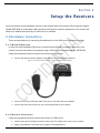
Setup the Receivers
You must connect each ScreenBeam receiver to the network with the Actiontec USB-to-Ethernet adapter
(model SBETH100) or ScreenBeam USB Transmitter and have the receivers powered on. The receiver will
obtain an IP address automatically if a DHCP server is available.
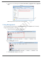
2.1 Hardware Connection
There are two solutions for connecting ScreenBeam Pro to the CMS server: wired and wireless.
2.1.1 Wired Connection
In order for the ScreenBeam CMS server to communicate with the ScreenBeam Receivers, each
receiver must be connected to the network using a USB-to-Ethernet adapter (Model: SBETH100).
Follow the procedure below to connect the receiver to a CMS server:
1. Connect the USB-to-Ethernet adapter to the USB port on the ScreenBeam Receiver.
Figure 2.1-1. Example of Education Edition 2 receiver with USB-to-Ethernet adapter
2. Connect one end of an Ethernet cable to the port on the USB-to-Ethernet adapter.
3. Connect the other end to a port on your router/switch/hub on your network.
2.1.2 Wireless Connection
Follow the procedure below to connect the receiver to a CMS server:
1. Prepare and properly configure a wireless router (AP). Then deploy this router in your network.
2. Plug the ScreenBeam Transmitter to the USB port of ScreenBeam Pro.
ScreenBeam Central Management System
Page 32
Figure 2.1-2. Example of Education Edition 2 receiver with USB-to-Wireless adapter
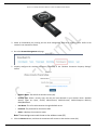
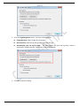
3. Power on ScreenBeam Pro, and log into the local management web server of the receiver. Refer to the
receiver’s user manual for details.
4. Go to the Remote Management tab page.
Figure 2.1-3
5. Properly configure the wireless connection parameters in the “Wireless Connection Property Settings”
section.
Figure 2.1-4
•
Network Name: The SSID of the wireless router (AP).
•
Security Type: Select a security type, the one you have selected on your wireless router. Available
security types are Open, Shared, WPA-Personal, WPA2-Personal, WPA2-Enterprise (802.1x),
PEAP/MsCHAPv2.
•
User Name: This is for authentication through a RADIUS server.
•
Password: The password for the wireless SSID.
•
Status: It displays the connection states
Note: These settings must match those on the wireless router (AP).
6. Click the Connect button, and then the transmitter will connect to the wireless router (AP).
ScreenBeam Central Management System
Page 33
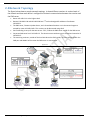
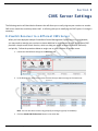
2.2 Network Topology
The figure below shows a sample network topology. It shows different receivers in various levels of
the network and how each device is configured to maintain communication between the receiver and
the CMS server.
Router 192.198.2.1 is at the highest level
Routers 192.168.2.100 and 192.168.2.200 are 2nd level and assigned IP addresses from Router
192.198.2.1
The CMS server, Firmware Update Server, and a ScreenBeam Receiver are in the network segment
created by router 192.168.2.100. This receiver can be discovered using UPnP.
Port forwarding is set up for the two servers: 7237, 7238 to the CMS server and 81 for the Web server
Corporate DNS server has IP 192.168.2.2. The domain server.aeisbcms.com is entered and routed to IP
192.168.1.5.
The remaining receivers, outside of the local LAN where the CMS resides, must be configured with the
CMS port and WAN IP of the router the CMS server is connected to.
Figure 2.2-1
ScreenBeam Central Management System
Page 34
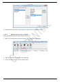
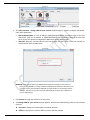
2.3 Configuring a Receiver ’s Network Interface
ScreenBeam receivers are set to acquire an IP address using DHCP by default (recommended).
However, you can set a static IP and define a DNS server for each receiver. Follow the procedure
below to set up a receiver’s network interface using a USB flash drive:
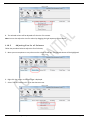
1. Connect a USB flash drive to a USB port on the CMS server.
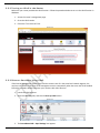
2. Open the CMS software, go to the Discovery tab, and click the USB Auto Configure Receiver button.
Figure 2.3-1
3. The ScreenBeam CMS – USB Auto Configuration window appears.
Figure 2.3-2
4. Select the Remote Management Settings for Receiver option and click the Next button to continue.
5. The Remote Management Settings for Receiver page appears. Select the TCP/IP Settings option, and
configure IP and DNS settings.
Auto (IP Policy/DNS Policy): When you choose this option, the receiver will obtain an IP address and a
DNS server IP address automatically from the network DHCP server.
Static (IP Policy/DNS Policy): When you choose this option, you can define an IP address and a DNS
server IP address for the receiver.
ScreenBeam Central Management System
Page 35
Figure 2.3-3
6. Select your USB flash drive in the Select a USB drive drop-down box, and then click Save to save the settings
to the selected USB flash drive.
7. Safely remove the USB flash drive from the server and then plug it to the receiver.
Note: The receiver must be in the idle state. You may disconnect the USB-to-Ethernet adapter at
this point if it is connected to the receiver.
8. The receiver configures itself with the settings saved in the USB flash drive, and reboots. The configuration
status will be displayed on the display device where the receiver is connected.
Figure 2.3-4
9. After the reboot, the receiver is configured successfully. You can check the IP address of the receiver, which
is displayed on the connected display device.
10. Remove the USB flash drive from the receiver and reconnect the USB-to-Ethernet adapter to connect the
receiver to the network.
ScreenBeam Central Management System
Page 36
Section 3
Discovering Receivers
The following section will help you discover and add ScreenBeam receivers to your CMS server. There are
three methods to discovering receivers: DNS Discovery, UPnP, or USB Drive method. DNS Discovery is the
recommended method, but requires a corporate DNS that you can manage. UPnP will work for receivers that
are in the same local network as your CMS server. Otherwise, you will have to use the USB method. We will
guide you through using each method below.
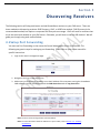
3.1 Setup Port Forwarding
You must set Port Forwarding on the router the Central Management Server is connected. The
following are generic steps for setting up port forwarding. Please refer to your router manual for
specific instructions.
1. Login to the router's management page.
Figure 3.1-1
2. Navigate to the Port Forwarding section.
3. Add an entry, with the server IP address set to the IP address of the computer running the ScreenBeam
CMS software. You will need forward both the CMS Server Port and the Log Server Port.
Figure 3.1-2
Note: The server must be assigned with a fixed IP address.
Note: For more information about the CMS server’s port number, refer to Section 1.4 - Installing
the Software.
ScreenBeam Central Management System
Page 37
3.2 DNS Discovery
The DNS Discovery method is the simplest way to have all your ScreenBeam receivers discovered by
the CMS server. It requires very little user interaction once your network is configured properly.
Note: You should carefully plan your network. In a DNS environment, changing IP address may take a
long time (hours to days) to take effect.
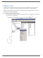
3.2.1 Configure DNS and DHCP Servers
ScreenBeam Pro Wireless Display Receiver supports DHCP Option 15. They can obtain domain information
from the DHCP server automatically.
1. Add a DNS record for the ScreenBeam CMS host to your corporate DNS server.
Figure 3.2-1
ScreenBeam Central Management System
Page 38
Figure 3.2-2
Note:
The default hostname for the CMS is “aeisbcms”. By default, ScreenBeam Pro Wireless Display
Receivers will resolve this hostname first.
ScreenBeam receivers can resolve a domain name with six labels at most.
If your ScreenBeam CMS hostname is too long or difficult to remember, you can add an alias name (CNAME)
for the ScreenBeam CMS host.
Figure 3.2-3
ScreenBeam Central Management System
Page 39
Figure 3.2-4
2. Configure the DHCP servers used to provision network addresses to the ScreenBeam receivers to assign
this DNS to its clients. Define the DNS server and the address pool.
Figure 3.2-5
3. Enable the Option 15 in the DHCP server, and define the domain that you use to manage the receivers.
ScreenBeam Central Management System
Page 40
Figure 3.2-6
Note: If Option 15 is not available on your DHCP server, neglect this step. In this case, you need to use
the Full Qualified Domain Name (FQDN).
3.2.2 Deploy the ScreenBeam Receivers
1. Launch the ScreenBeam CMS software.
2. Verify your ScreenBeam receivers are powered on and connected to your network through the USB-toEthernet adapter.
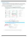
3. When the receivers are assigned an IP they will automatically connect to the CMS server. You should
see the ScreenBeam receivers appear listed on the Receiver Pane on the CMS software.
Figure 3.2-7
ScreenBeam Central Management System
Page 41
3.3 UPnP Discovery
UPnP may be the quickest method to discovering your ScreenBeam receivers. However, this method
will only work if the CMS server and your ScreenBeam receivers are all on the same local network. You
must first turn on UPnP in Windows and the routers before performing the UPnP discovery.
3.3.1 Turning on UPnP in Windows
1. In Windows open Control Panel, locate and select Network and Sharing Center
Figure 3.3-1
2. In the left pane, click the link for Change advanced sharing settings
Figure 3.3-2
3. In the Network discovery section, select the option for Turn on network discovery
ScreenBeam Central Management System
Page 42
Figure 3.3-3
4. Click Save changes to save the settings
ScreenBeam Central Management System
Page 43
3.3.2 Turning on UPnP in the Router
Make sure your router provides the UPnP function. Follow the procedure below to turn on the UPnP function in
Windows:
1. Access the router’s management page.
2. Go to the UPnP section.
3. Check the “Turn UPnP On” box.
Figure 3.3-4
3.3.3 Discover Receivers Using UPnP
If the Central Management System server and the receivers are all in the same local network segment, the
receivers can discover and report to the management server automatically when the server has UPnP enabled.
Follow the procedure below to discover your receivers with UPnP function.
1. Launch the CMS software.
2. Select the Discovery tab, and click the Start up UPnP button.
Figure 3.3-5
3. The ScreenBeam CMS – UpnP Settings box appears.
ScreenBeam Central Management System
Page 44
Figure 3.3-6
4. Properly configure CMS IP/Domain/Host and CMS Port. Click the Start UPnP button to start the UPnP
function on the CMS server.
CMS IP/Domain/Host: It is the IP address, or FQDN/hostname/domain name/alias name of the new
CMS server. Enter the IP address, or FQDN/hostname/domain name/alias name of the new CMS
server (if you have properly configured the DNS server and the DHCP server).
CMS Port: Receivers communicate with the CMS through this port. Enter a port number for
communication with the CMS server.
5. The receivers will discover and report to the CMS server. This process may take several minutes. After
the receiver connects to the CMS server, its state changes to “Connected to CMS: xxx.xxx.xxx.xxx”, which
is displayed on the HDTV.
Note: You must enable the SSDP Discovery service in the operating system for this feature to work properly. See
Section 1.3 – Preparing the System for details.
6. If you want to stop UPnP Discovery, open the ScreenBeam Central Management System – UpnP
Settings box again, and click the Stop UPnP button.
Figure 3.3-7
ScreenBeam Central Management System
Page 45
3.4 Discover Receivers Using a USB Drive
If UPnP, or DNS Discovery, are not available methods for discovering your receivers, you will need to
manually configure each receiver using a USB flash drive. This only needs to be done once during initial
setup. Once set, the receivers can be configured remotely using the CMS software.
Note: Before configuring a receiver with the USB drive, you must properly configure the server (the IP address
(or domain name/host name) and port). See Section 8.2 Modify CMS Server Settings for details.
Follow the procedure below to discover your receivers with a USB flash drive.
1. Connect a USB flash drive to the CMS server computer.
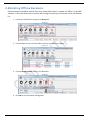
2. Launch the CMS software and go to the Discovery tab.
3. Click the USB Auto Configure Receiver button.
Figure 3.4-1
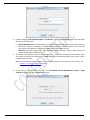
4. The ScreenBeam CMS – USB Auto Configuration box appears.
Figure 3.4-2
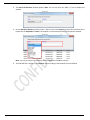
5. Select the CMS Settings for Receiver option, and click the Next button to go to CMS Settings page.
ScreenBeam Central Management System
Page 46
Figure 3.4-3
CMS IP/Domain/Host: It is the IP address, or FQDN/hostname/domain name/alias name of the new
CMS server (if you have properly configured the DNS server and the DHCP server).
Note: The SCMS IP Address is the WAN IP address to which the PC is mapped to, if the PC is behind a
NATed router.
CMS Port: Receivers communicate with the CMS through this port.
6. Select your USB flash drive in the Select a USB drive drop down, and then click Save to save the settings
to the selected USB flash drive.
7. Remove the USB flash drive from the CMS server and plug it into the USB port on the ScreenBeam
receiver (which is in standby state).
8. The receiver configures itself and will automatically reboot. After the reboot, the receiver is configured
successfully.
Figure 3.4-4
9. Remove the USB flash drive from the receiver and connect the receiver to the network.
ScreenBeam Central Management System
Page 47
3.5 Deleting Offline Receivers
Disconnecting a ScreenBeam receiver from your network will cause it to appear as “offline” in the CMS
software. In the case where such a receiver will no longer be used you can remove it from the Receiver
list.
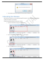
1. Launch the CMS software and go to the Group tab.
Figure 3.5-1
2. From the Receiver list, select the offline receivers you would like to delete.
Figure 3.5-2
3. Click the Delete Receiver button in the Action Bar.
Figure 3.5-3
4. Click OK on the confirmation message box.
ScreenBeam Central Management System
Page 48
Figure 3.5-4
5. The selected receivers will be deleted and removed from the Receiver List.
3.6 Locating Your Receiver
With the Search function, you can easily locate specific receivers in case you have deployed a large
number of receivers in your system.
Follow the procedure below to locate your receivers,
1. Launch the CMS software and go to the Options tab.
Figure 3.6-1
2. Choose the Receiver Pane or Group Pane (or a specific group).
Figure 3.6-2
3. Select the Search button from the Action Bar.
Figure 3.6-3
ScreenBeam Central Management System
Page 49
4. The Search for Receiver window appears. Note: You can also press the “Ctrl + F” keys to display this
window.
Figure 3.6-4
5. On the Search for Receiver window, select a search scope in the Scope drop-down box, and then type a
keyword in the Keyword box. Note: The keyword is case sensitive and only one keyword is allowed.
Figure 3.6-5
Note: You can not search in the Receiver Status and Receiver Feedback columns.
6. The CMS will filter receivers in the Receiver pane according to the keyword you have defined.
ScreenBeam Central Management System
Page 50
Section 4
Group Management
The ScreenBeam Central Management System allows you to group any number of ScreenBeam Receivers into
groups for better organization and simplified batch management. Group Management allows you to create
multiple top level groups, and also multiple sub-groups within higher level groups.
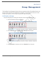
4.1 Create a Group
This section will guide you in creating your initial group, and then adding sub-level groups.
1. Launch the CMS software and go to the Group tab.
Figure 4.1-1
2. Click the Add Group button. The Manage Group – Add Group window will appear.
Figure 4.1-2
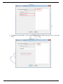
3. Select (Root Group) on the right pane, then enter a Group Name for your new group.
ScreenBeam Central Management System
Page 51
Figure 4.1-3
4. Click Save to save the group. You will see the new group listed on the right pane (also in the Group
Pane).
Figure 4.1-4
ScreenBeam Central Management System
Page 52
Figure 4.1-5
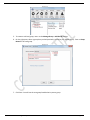
5. To create a sub-level group, return to the Manage Group – Add Group window.
6. On the right pane, select a group that you had previously created as your Parent Group. Enter a Group
Name for this new group.
Figure 4.1-6
7. Click Save. You will see the new group listed below its parent group.
ScreenBeam Central Management System
Page 53
Figure 4.1-7
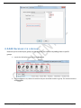
4.2 Add Receivers to a Group
Now that you’ve created your groups you can organize your receivers by adding them to specific
groups.
1. Launch the CMS software and go to the Group tab.
Figure 4.2-1
2. From the Receiver List, select the receivers that you would like to add to a group. The selected receivers
are highlighted.
ScreenBeam Central Management System
Page 54
Figure 4.2-2
3. On the Action Bar, select Join to Group. This will open the Join to Group window.
Figure 4.2-3
4. On the left pane select the group that you would like to assign for the selected receivers. Click the Join
button to continue.
Figure 4.2-4
5. The receivers will now be in a group. You will see a success message on the screen.
ScreenBeam Central Management System
Page 55
Figure 4.2-5
Note: A receiver can join and belong to multiple groups.
Note: In the Group Pane, selecting a parent group will also automatically select the child groups
and its members.
4.3 Release Receivers from a Group
Follow the procedure below to release receivers from their respective groups.
1. Launch the CMS software and go to the Group tab.
Figure 4.3-1
2. From the Receiver List, select the receivers you would like to release. You can also select all the
receivers in a group by selecting the group in the Group Pane.
ScreenBeam Central Management System
Page 56
Figure 4.3-2
3. On the Action Bar select Release from Group.
Figure 4.3-3
4. The Release from Group window appears. Select a receiver from the Receiver Name drop down list.
Figure 4.3-4
5. The group(s) which the selected receiver belongs to appears in the Group Information pane. Click a
group name to select it – click it again to de-select it.
ScreenBeam Central Management System
Page 57
Figure 4.3-5
6. Click the Delete button to remove the receiver from the selected group. Repeat the process for other
receivers.
Figure 4.3-6
4.4 Modify a Group
Follow the steps below to modify a group, particularly the group name.
1. Launch the CMS software and go to the Group tab.
ScreenBeam Central Management System
Page 58
Figure 4.4-1
2. Click the Modify Group button. The Manage Group – Modify Group window appears.
Figure 4.4-2
3. Select a group from the right pane. Once selected you can modify the Group Name in the left pane.
Figure 4.4-3
4. Click Save to make the change.
4.5 Delete a Group
This section will guide you in deleting your group.
1. Launch the CMS software and go to the Group tab.
ScreenBeam Central Management System
Page 59
Figure 4.5-1
2. Select the Delete Group button.
Figure 4.5-2
3. The Manage Group – Delete Group window appears. Select the group to be deleted from the right
pane.
Figure 4.5-3
4. Click the Delete button to delete the selected group.
Note: All child groups will be deleted if you delete their parent group.
ScreenBeam Central Management System
Page 60
ScreenBeam Central Management System
Page 61
Section 5
Receiver Settings
This section will guide you on making changes to the various settings on the ScreenBeam receivers. The
ScreenBeam Central Management System allows you to make changes to a single receiver or to a batch of
receivers.
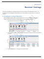
5.1 Configure a Single Receiver
When configuring a single receiver you will be able to see all the current settings for the selected
receiver, and also have the ability to make changes to any setting for that receiver.
1. Launch the CMS software and go to the Policy tab.
Figure 5.1-1
2. On the Receiver List, select a single receiver by clicking the Receiver Name of the device you would like
to configure.
Figure 5.1-2
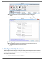
3. Click the Settings button. The configuration window will appear.
ScreenBeam Central Management System
Page 62
Figure 5.1-3
Note: You can also double-click a receiver on the Receiver Pane to open the configuration
window.
4. Make necessary changes to the parameters and click Save to save your settings.
Figure 5.1-4
Note: You can also access the receiver’s local management server and configure the receiver. For
more detail, please refer to the receiver’s user manual.
5.2 Configure Multiple Receivers
When configuring multiple receivers, you are given a select group of settings which can be configured
in a batch. Once executed, the CMS server will send the configuration to all the receivers at once and
the changes are made instantly.
1. Launch the CMS software and go to the Policy tab.
ScreenBeam Central Management System
Page 63
Figure 5.2-1
2. On the Receiver List, select two or more receivers.
Figure 5.2-2
Note: You may also select multiple receivers by selecting one or more groups from the Group
Pane.
3. Click the Settings button. The configuration window will appear.
Figure 5.2-3
4. Select the items you want to configure (have the checkboxes checked), and make necessary changes to
them. Click Execute to save your settings to the selected receivers.
Select All: Click this button, all configuration items in this page will be selected.
Select None: Click this button, all selected items will be deselected.
WARNING! Make sure all the settings, even those not modified, are correct. When batch
configuring, all the settings previously configured on the receiver will be overwritten with
those set on this page.
ScreenBeam Central Management System
Page 64
Figure 5.2-4
Note:
Only the selected receivers will be configured. For further details on each configuration
setting, please refer to the receiver’s user manual.
The features displayed in this page depend on the types of ScreenBeam receivers.
5. Click Execute to execute the policy for the selected receivers.
6. The Change Settings for your receiver window appears, which shows receiver setup status for the
selected receivers.
Selected: It displays the total number of selected receivers.
Offline: It displays the number of offline receivers that are selected.
Online: It displays the number of online receivers that are selected.
Policy delivery succeeded: It displays the number of receivers to which the policy is delivered.
Policy delivery failed: It displays the number of receivers to which the policy is not delivered.
Policy execution succeeded: It displays the number of receivers that have successfully executed the
policy.
Policy execution failed: It displays the number of receivers that have failed to execute the policy.
ScreenBeam Central Management System
Page 65
Figure 5.2-5
Note: The Change Settings for your receiver window will not appear if just one receiver is selected.
7. After the policy is executed, click the Close button to close the window.
Note: You can click the Hide button to hide this window. In this case, a Show button is display in the top
right corner of the receiver pane. Click this button to display the window again.
5.3 Configuring Receivers using a USB Flash Drive
You can also use a USB flash drive to configure ScreenBeam receivers. Follow the procedure below to
configure a receiver using a USB flash drive:
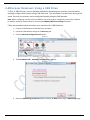
1. Connect a USB flash drive to a USB port on the CMS server.
2. Open the CMS software, go to the Discovery tab, and click the USB Auto Configure Receiver button.
Figure 5.3-1
3. The ScreenBeam CMS – USB Auto Configuration window appears.
ScreenBeam Central Management System
Page 66
Figure 5.3-2
4. Select one configuration category and click the Next button to continue.
CMS Settings for Receiver: Settings for CMS discovery are provided. Refer to Section 3.4 Discover
Receivers Using a USB Drive for details.
Remote Management Settings for Receiver: CMS discovery settings, network interface settings, and
Wi-Fi module connection settings are provided. For details about setting the network interface, refer to
Section 2.3 Configuring a Receiver’s Network Interface; and for details about setting the Wi-Fi module
connection, refer to Section 2.1.2 Wireless Connection.
All Settings for Receiver: General settings for ScreenBeam receivers, except firmware update,
screensaver image update, and standby background image update, are provided. Refer to the receiver’s
User Manual for details.
5.4 Setting the Screen Saver Image
The ScreenBeam Receiver’s screen saver can be customized to include your own picture or logo.
5.4.1 Screen Saver Image Requirements
The requirements for the screen saver image are as following:
The image must be in a Portable Network Graphics (PNG) format.
The recommended image dimensions are 300 x 60 pixels (width x height).
The file size of the image must be less than 200 KB.
The image must reside in a Web server accessible by the receivers.
5.4.2 Setting the Screensaver Image
Follow the procedure below to set the screensaver image for one or more receivers.
1. Launch the CMS software and go to the Policy tab.
ScreenBeam Central Management System
Page 67
Figure 5.4-1
2. In the Receiver List, select one or more receivers.
Figure 5.4-2
Note: You can also select multiple receivers by selecting one or more groups from the Group
Pane.
3. Click Set Screen saver from the Action Bar.
Figure 5.4-3
4. The Policy Contents – Customize Screen Saver for your receiver window appears. Enter the full URL
address of the screensaver image file in the text box, e.g. “http://192.168.5.60:8080/update/sceen.png”.
ScreenBeam Central Management System
Page 68
Figure 5.4-4
Note: You may optionally click on the Verify URL button to have the CMS server check if the URL
is valid. This feature only works if the Web server and the CMS server are in the same
local network.
5. Click Execute to update the screen saver image for the selected receivers.
6. The Customize Screen saver for your receiver window appears, which shows screen saver image update
status for the selected receivers.
Selected: It displays the total number of selected receivers.
Offline: It displays the number of offline receivers that are selected.
Online: It displays the number of online receivers that are selected.
Policy delivery succeeded: It displays the number of receivers to which the policy is delivered.
Policy delivery failed: It displays the number of receivers to which the policy is not delivered.
Policy execution succeeded: It displays the number of receivers that have successfully executed the
policy.
Policy execution failed: It displays the number of receivers that have failed to execute the policy.
ScreenBeam Central Management System
Page 69
Figure 5.4-5
Note: The Customize Screen saver for your receiver window will not appear if just one receiver is
selected.
7. After the policy is executed, click the Close button to close the window.
Note: You can click the Hide button to hide this window. In this case, a Show button is display in the top
right corner of the receiver pane. Click this button to display the window again.
5.5 Setting a Background Image
The ScreenBeam Receiver’s Background (the Ready To Connect screen) can be customized to include
your own picture or logo.
5.5.1 Background Image Requirements
The requirements for the background image are as following:
The image must be in .png and .jpeg/.jpg formats.
The file size must not exceed 2.5 MB.
The best image size is 1280*720 pixels (width x height).
The image must reside in a Web server accessible by the receivers.
5.5.2 Setting a Background Image
Follow the procedure below to set the background image for one or more receivers.
1. Launch the CMS software and go to the Policy tab.
ScreenBeam Central Management System
Page 70
Figure 5.5-1
2. In the Receiver List, select one or more receivers.
Figure 5.5-2
Note: You can also select multiple receivers by selecting one or more groups from the Group
Pane.
3. Click Set Background from the Action Bar.
Figure 5.5-3
4. The Policy Contents – Set Background for your receiver window appears. Enter the full URL address of
the background image file in the text box, e.g. “http://192.168.5.60:8080/update/background.png”.
ScreenBeam Central Management System
Page 71
Figure 5.5-4
Note: You may optionally click on the Verify URL button to have the CMS server check if the URL
is valid. This feature only works if the Web server and the CMS server are in the same
local network.
5. Click Execute to update the background image for the selected receivers.
6. The Set Background for your receiver window appears, which shows background update status for the
selected receivers.
Selected: It displays the total number of selected receivers.
Offline: It displays the number of offline receivers that are selected.
Online: It displays the number of online receivers that are selected.
Policy delivery succeeded: It displays the number of receivers to which the policy is delivered.
Policy delivery failed: It displays the number of receivers to which the policy is not delivered.
Policy execution succeeded: It displays the number of receivers that have successfully executed the
policy.
Policy execution failed: It displays the number of receivers that have failed to execute the policy.
ScreenBeam Central Management System
Page 72
Figure 5.5-5
Note: The Set Background for your receiver window will not appear if just one receiver is selected.
7. After the policy is executed, click the Close button to close the window.
Note: You can click the Hide button to hide this window. In this case, a Show button is display in the top
right corner of the receiver pane. Click this button to display the window again.
ScreenBeam Central Management System
Page 73
Section 6
Updating Receiver Firmware
The ScreenBeam Central Management System allows you to upgrade the firmware for multiple receivers from
a single location. This feature requires you to host the firmware image file on a web server, as we will
describe below. Once hosted, each receiver will download the image and perform the update without
requiring any user interaction.
6.1 Firmware Update Server
An HTTP server is required for performing firmware updates. This can be any HTTP server that is
accessible by the network that your ScreenBeam receivers are connected to. The firmware image files,
and also the screensaver/background image files, will reside in this server. Below are some notes
regarding setting up your HTTP server:
1. If you are setting up your own HTTP server, we suggest using a fixed IP address. This IP will be required
for entering into the URL if the receivers are not connected to a DNS server.
2. Copy the firmware image file to a folder in your server. DO NOT rename the firmware image files. They
should remain named install.img.
Note: The firmware file is in the “.img” format. You must enable support for the “.img” on your
web server.
Note: If you would like to maintain multiple firmware image files, we suggest putting them into
separate folders.
3. If the server resides behind a firewall, make sure to forward all the necessary ports required to get HTTP
access to the server.
Note: You may setup the HTTP server on the same system running the CMS software. However,
you may still have to open ports on your firewall so that the ScreenBeam receivers can
access both the CMS software and the HTTP files.
6.2 Update the Receiver Firmware
The following section will guide you to updating the firmware for one or more receivers. Updating can
take up to 20 or more minutes, depending on network bandwidth. It is suggested to perform updates
during off hours.
Note: Perform updates in smaller groups of receivers, so as not to saturate the network.
1. Launch the CMS software and go to the Policy tab.
ScreenBeam Central Management System
Page 74
Figure 6.2-1
2. In the Receiver List, select one or more receivers.
Figure 6.2-2
Note: You can also select receivers by selecting groups.
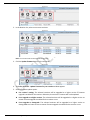
3. Click the Update Firmware button in the Action Bar.
Figure 6.2-3
4. The Policy Contents - Update Firmware for your receiver window appears.
5. Select a firmware update option.
Per receiver’s setting: The selected receivers will be upgraded to a higher version if firmware
upgrade is enabled for the receiver. Otherwise, the receiver’s firmware will not be updated.
Force upgrade to a higher version: The selected receivers will be upgraded to a higher version no
matter firmware upgrade is enabled for the receiver or not.
Force upgrade or downgrade: The selected receivers will be upgraded to a higher version or
downgraded to a lower version no matter firmware upgrade is enabled for the receiver or not.
ScreenBeam Central Management System
Page 75
Figure 6.2-4
6. Type the full URL address of the firmware
“http://192.168.5.60:8080/update/install.img”.
image
file
in
the
URL
field,
e.g.
Figure 6.2-5
Note: You may optionally click on the Verify URL button to have the CMS server check if the URL
is valid.
Note: You must enter an IP address here; even you deploy your web server locally. An URL
address such as “http://localhost/update/install.img” will not work.
7. Click the Execute button to perform the update for the selected receivers.
8. The Update Firmware for your receiver window appears, which shows firmware update status for the
selected receivers.
ScreenBeam Central Management System
Page 76
Selected: It displays the total number of selected receivers.
Offline: It displays the number of offline receivers that are selected.
Online: It displays the number of online receivers that are selected.
Policy delivery succeeded: It displays the number of receivers to which the policy is delivered.
Policy delivery failed: It displays the number of receivers to which the policy is not delivered.
Policy execution succeeded: It displays the number of receivers that have successfully executed the
policy.
Policy execution failed: It displays the number of receivers that have failed to execute the policy.
Figure 6.2-6
Note: The Update Firmware for your receiver window will not appear if just one receiver is selected.
9. Firmware update status is also displayed on the display devices that the receivers connect to and the
CMS server screen.
10. After the policy is executed, click the Close button to close the window.
Note: You can click the Hide button to hide this window. In this case, a Show button is display in the top
right corner of the receiver pane. Click this button to display the window again.
Note: After a firmware upgrade the ScreenBeam Receiver should retain its settings.
ScreenBeam Central Management System
Page 77
Section 7
Receiver Logs
ScreenBeam Wireless Display Receivers can record and transfer system logs for troubleshooting purposes. By
default, receiver logs remain within the ScreenBeam Receiver. The ScreenBeam Central Management System
allows you to configure receivers to upload these logs to an FTP server location or to the CMS server itself.
7.1 Enable Receiver Log Upload
In this section we will describe the type of events which are logged and then describe the procedure
for uploading the logs.
7.1.1 Logged Events
The following are the events which are logged by the ScreenBeam Receiver:
Reboots
Reset settings
Firmware updates
Connection initiated with a source device
Successful connections
Failed connections
Disconnections from the source device
7.1.2 Enabling Receiver Logging
The procedure below describes how to enable receiver log uploads.
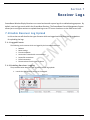
1. Launch the CMS software and go to the Log tab.
Figure 7.1-1
ScreenBeam Central Management System
Page 78
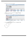
2. In the Receiver List, select one or more receivers.
Figure 7.1-2
Note: You can also select receivers by groups (by checking the groups’ check boxes).
3. Click Receiver Log on the Action Bar.
Figure 7.1-3
4. The Policy Contents - Receiver Log window appears. Set Log Upload to Enable.
ScreenBeam Central Management System
Page 79
Figure 7.1-4
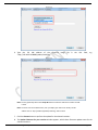
5. Define a log upload interval. By default, the upload interval is every 48 hours. You can define an interval
in the 1 – 999 (hours) range.
Figure 7.1-5
Note: If Immediately is selected, receivers will upload logs to the selected server immediately
after the log upload server is configured successfully.
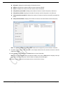
6. Select where to save the receiver logs.
ScreenBeam Central Management System
Page 80
Save logs to CMS: Logs are saved directly to a folder on the CMS server.
Save logs to FTP: Logs are saved to a remote FTP server. Enter the appropriate values for the chosen FTP
server.
Host: IP address of the FTP server.
Port: The port number for the FTP server.
Remote Directory: The directory where to save the receiver logs. If the directory that does not exist, the
FTP server will create this directory.
Anonymous: Select to use anonymous access to the FTP server. Make sure the FTP server allows
anonymous access.
User Name and Password: Enter the account credentials to use for access to the FTP server, if user
verification is required. You should obtain the username and password from your system administrator.
ScreenBeam Central Management System
Page 81
Figure 7.1-6
7. Click Execute, and the Receiver Log window appears, which shows log upload status for the selected
receivers.
Figure 7.1-7
8. The receivers will upload their logs to the FTP server or CMS periodically in accordance with the defined
interval.
Note: If no log is generated by a receiver during an interval, an empty file is uploaded to the
FTP/CMS server.
Note: If a log is not uploaded successfully the receiver will send a warning message to the CMS
server. This may occur, for instance, if the FTP server is down. These messages are
displayed on the Receiver Warning Message box, which pops up immediately when such
messages are received.
ScreenBeam Central Management System
Page 82
Note: If a log fails to upload successfully, the receiver will attempt to upload it again at the next
interval. If the log upload fails again, the log will be discarded.
ScreenBeam Central Management System
Page 83
7.2 Viewing Receiver Logs
ScreenBeam CMS allows you to view the ScreenBeam Receiver logs directly from the CMS software, if
the logs are saved locally to the CMS server.
1. Launch the CMS software and go to the Log tab.
Figure 7.2-1
2. Select Open Log Folder from the Action Bar.
Figure 7.2-2
3. This will open the ReceiverLog folder.
4. A separate folder for each receiver is created. The folder name will be the MAC address of the
ScreenBeam Receiver.
Figure 7.2-3
ScreenBeam Central Management System
Page 84
5. The log name is in the following format: <Receiver’s Mac Address>_<Logging Start Time>_<Logging End
Time>.
Figure 7.2-4
Note: Each log file contains only the events for a particular interval
7.3 Log Management
You can manage all your logs through the Log Management feature in the Options menu. For example,
change the log saving folder, or view logs.
1. Launch the CMS software and go to the Options tab.
Figure 7.3-1
2. Select Options from the Action Bar.
Figure 7.3-2
3. The ScreenBeam CMS – Options window appears.
ScreenBeam Central Management System
Page 85
Figure 7.3-3
4. Go to the Log Management section, and select a desired option.
Change Directory: Select a folder for saving logs.
Open Directory: Open the log saving folder, and check the logs.
Automatically open the log file when …: The CMS software will open the log when a policy is
executed for multiple receivers, if this option is selected (checked).
5. Click OK to save your settings.
ScreenBeam Central Management System
Page 86
Section 8
CMS Ser ver Settings
The following section will describe the features that will allow you to easily migrate your receivers to another
CMS server should the occasion present itself. It will also guide you to modifying the CMS’s ports if a change is
necessary.
8.1 Switch Receiver to a different CMS Server
When you have deployed multiple ScreenBeam Central Management System servers in your network,
you may need to reassign your receivers to these additional or replacement servers. ScreenBeam CMS
provides a simple server switch function, which can help you switch receivers to another CMS easily
and quickly. Follow the procedure below to assign one or more receivers to another server:
1. Launch the CMS software and go to the Discovery tab.
Figure 8.1-1
2. In the Receiver List, select one or more receivers that you want to assign to the new server.
Figure 8.1-2
Note: You can also select receivers by groups (by checking the groups’ checkboxes).
3. Click the Switch CMS for Receiver button in the Action Bar.
ScreenBeam Central Management System
Page 87
Figure 8.1-3
4. The Policy Contents - Change CMS for your receiver window appears. Properly configure and doublecheck these parameters.
CMS IP/Domain/Host: It is the IP address, FQDN/hostname/domain name/alias name of the new
CMS server. Enter the IP address, or FQDN/hostname/domain name/alias name of the new CMS
server (if you have properly configured the DNS server and the DHCP server).
CMS Port: Receivers communicate with the CMS through this port. Enter a new port number for
communication with the CMS server.
Figure 8.1-4
WARNING! Verify your IP address (or FQDN/hostname/domain name/alias name) and port
before clicking Execute. If a wrong IP address/ FQDN/hostname/domain name/alias name
or port is entered, the ScreenBeam CMS will no longer be able to communicate with the
receivers, and each receiver will need to be individually provisioned with a USB drive to
the new CMS settings.
5. Click Execute to assign the servers to the new server.
6. The Change CMS for your receiver window appears, which shows CMS switching status for the selected
receivers.
Selected: It displays the total number of selected receivers.
Offline: It displays the number of offline receivers that are selected.
ScreenBeam Central Management System
Page 88
Online: It displays the number of online receivers that are selected.
Policy delivery succeeded: It displays the number of receivers to which the policy is delivered.
Policy delivery failed: It displays the number of receivers to which the policy is not delivered.
Policy execution succeeded: It displays the number of receivers that have successfully executed the
policy.
Policy execution failed: It displays the number of receivers that have failed to execute the policy.
Figure 8.1-5
Note: The Change CMS for your receiver window will not appear if just one receiver is selected.
7. Click the Close button to close the window.
Note: You can click the Hide button to hide this window. In this case, a Show button is display in the top
right corner of the receiver pane. Click this button to display the window again.
ScreenBeam Central Management System
Page 89
8.2 Modify CMS Server Settings
ScreenBeam Central Management System allows you to change the current CMS’s ports.
Warning! If the ScreenBeam receivers are not set to detect the CMS server using DNS, then you must switch
all receivers to the new server before changing the CMS’s port. Otherwise, receivers will not communicate
with the new CMS, and you have to configure these receivers with a USB flash drive.
Note: Refer to Section 8.1 – Switch Receiver to a different CMS Server for details.
Note: Refer to Section 3.4 – Discover Receivers using a USB Drive for discovering receivers using
a USB drive.
2. Launch the CMS software and go to the Discovery tab.
Figure 8.2-1
3. Click on Configure Server from the Action Bar.
Figure 8.2-2
4. The ScreenBeam CMS – Communication Ports window appears. Properly configure and double-check
these parameters.
CMS Communication Port: Receivers communicate with the CMS through this port. Enter a new
port number for communication with the CMS server.
Log Upload Port: Receivers upload logs to the CMS through this port. Enter a new port number to
use for saving receiver logs to the CMS server.
ScreenBeam Central Management System
Page 90
Figure 8.2-3
5. Click the Save button to save the new server settings. You must restart the CMS in order for the new
setting to take effect.
Figure 8.2-4
ScreenBeam Central Management System
Page 91
Section 9
Receiver Maintenance
With the CMS server you can perform some remote management on the ScreenBeam receivers in your
network. The CMS software will allow you to remotely reboot or reset to factory defaults one or more
receivers.
9.1 Reboot Receivers
Follow the procedure below to remotely reboot the selected ScreenBeam receiver(s):
1. Launch the CMS software and go to the Policy tab.
Figure 9.1-1
2. In the Receiver List, select one or more receivers to reboot.
Figure 9.1-2
Note: You can also select receivers by groups in the Group Pane.
3. Click Reboot on the Action Bar.
ScreenBeam Central Management System
Page 92
Figure 9.1-3
4. A message box appears. Click OK to continue.
Figure 9.1-4
5. The Reboot for your receiver window appears, which shows receiver reboot status for the selected
receivers.
Selected: It displays the total number of selected receivers.
Offline: It displays the number of offline receivers that are selected.
Online: It displays the number of online receivers that are selected.
Policy delivery succeeded: It displays the number of receivers to which the policy is delivered.
Policy delivery failed: It displays the number of receivers to which the policy is not delivered.
Policy execution succeeded: It displays the number of receivers that have successfully executed the
policy.
Policy execution failed: It displays the number of receivers that have failed to execute the policy.
ScreenBeam Central Management System
Page 93
Figure 9.1-5
Note: The Reboot for your receiver window will not appear if just one receiver is selected.
6. The selected receivers will reboot immediately.
7. Click the Close button to close the window.
Note: You can click the Hide button to hide this window. In this case, a Show button is display in the top
right corner of the receiver pane. Click this button to display the window again.
9.2 Restore Receiver Factory Defaults
Follow the procedure below to remotely reset the selected ScreenBeam receiver(s):
1. Launch the CMS software and go to the Policy tab.
Figure 9.2-1
2. In the Receiver List, select one or more receivers to reset.
ScreenBeam Central Management System
Page 94
Figure 9.2-2
Note: You can also select receivers by groups in the Group Pane.
3. Click the Reset to Default button on the Action Bar.
Figure 9.2-3
4. A confirmation window will appear. Click OK to continue.
Figure 9.2-4
Note: The following data will be preserved and not restored to factory defaults:
CMS Server IP address
ScreenBeam Central Management System
Upload LOG Control
Page 95
CMS Server Port
Receiver IP Policy (DHCP or
Static IP)
Receiver IP address
Receiver Subnet Mask
Receiver Gateway
Receiver DNS Policy
(Dynamic or Static)
Primary DNS
Secondary DNS
Receiver Host Name
(Enable or Disable)
Log upload location
Log upload interval
FTP Login Control (Enable
or Disable)
FTP login user name
FTP login password
Wireless connection
settings
5. The Reset for your receiver window appears, which shows receiver reset status for the selected
receivers.
Selected: It displays the total number of selected receivers.
Offline: It displays the number of offline receivers that are selected.
Online: It displays the number of online receivers that are selected.
Policy delivery succeeded: It displays the number of receivers to which the policy is delivered.
Policy delivery failed: It displays the number of receivers to which the policy is not delivered.
Policy execution succeeded: It displays the number of receivers that have successfully executed the
policy.
Policy execution failed: It displays the number of receivers that have failed to execute the policy.
Figure 9.2-5
Note: The Reset for your receiver window will not appear if just one receiver is selected.
6. The selected receivers will restore to defaults immediately and reboot.
7. Click the Close button to close the window.
Note: You can click the Hide button to hide this window. In this case, a Show button is display in the top
right corner of the receiver pane. Click this button to display the window again.
ScreenBeam Central Management System
Page 96
9.3 Receiver Description
This section will guide you in setting location information and additional information for receivers.
1. Launch the CMS software and go to the Group tab.
Figure 9.3-1
2. From the Receiver List, select one or more receivers that you would like to add descriptions. The
selected receivers are highlighted.
Figure 9.3-2
3. Click the Receiver Description button.
Figure 9.3-3
4. The Receiver Description window appears.
ScreenBeam Central Management System
Page 97
Figure 9.3-4
5. Type location information and additional information for the selected receivers in the Receiver Location
box and the Note box respectively.
Figure 9.3-5
Note: When you select more than one receivers, you must note that new descriptions will overwrite the
previous ones.
6. Click OK to save the descriptions. You can see your descriptions in the Receiver Location and Note
columns.
Note: By default, the Receiver Location and Note columns are hidden. Refer to Section 1.6.2 Hiding or
Showing Columns for details.
ScreenBeam Central Management System
Page 98
Section 10
Troubleshooting
If your ScreenBeam Central Management System experiences problems, you may be able to resolve it with
some help from the commonly encountered problems and their solutions as outlined in the table below.
Problem
My ScreenBeam Receiver is not
connecting to the CMS server.
I have started the UPnP discovery
in ScreenBeam CMS, but no
receiver is discovered.
Cause
Solution
The receiver does not have
an IP address
Check if the receiver is assigned with an IP address. You can
check this in the lower right corner. If you see "Ethernet IP:
xxx.xxx.xxx.xxx", your receiver is assigned an IP address. If no
"Ethernet IP" is displayed, the receiver is not assigned an IP
address. Then, you should check the router, cable connection,
and/or USB-to-Ethernet adapter.
The receiver has not been
configured with the proper
CMS parameters.
Check if the receiver is provisioned with the CMS server's IP
address and port number. By default, the receiver is set to
connect to the CMS through the domain name
"server.aeisbcms.com". You can check this in the lower right
corner. You should see "Connected to MGT:
server.aeisbcms.com"/"Disconnected from MGT:
server.aeisbcms.com". If you have set the receiver to connect to
the CMS through the server's IP address, you should see
"Connected to MGT: xxx.xxx.xxx.xxx"/"Disconnected from MGT:
xxx.xxx.xxx.xxx". Then you should check if this IP address is the
IP address of the CMS server. If not, you must correct it. If no
“Disconnected” or “Connected” message is displayed, you
should check the router, cable connection, and/or USB-toEthernet adapter.
Corporate DNS server has
not been configured.
Check if the domain name "server.aeisbcms.com" is added to
the DNS server if you have deployed a DNS server. The domain
name "server.aeisbcms.com" must pair with the IP address of
the CMS server.
Port forwarding not setup
properly.
Check if you have properly configured port forwarding for the
CMS server. Access the configuration page of the router that the
CMS server connects to, and check the port forwarding page.
UPnP is not properly enabled
or SSDP service is not
started.
Check if UPnP is enabled in Windows. If not, enable UPnP in
Windows. Refer to Section 3.3.1 for details.
Check if the SSDP Discovery service is started. If not, start the
SSDP Discovery service. Refer to Section 1.3 for detail.
Check if UPnP is enabled on your router. If not, enable UPnP in
ScreenBeam Central Management System
Page 99
Problem
Cause
Solution
the router. Refer to Section 3.3.2 for details.
Port forwarding needs to be
configured.
Probably, port forwarding is not correctly configured for the
CMS. Check the port forwarding on the connected router. And
configure it correctly.
My CMS does not respond or
becomes slow to react when
many receivers are being
connected simultaneously.
CMS server system specs not
powerful enough.
The CMS requires a lot of computer resources to process
information of simultaneous connections to many receivers,
which cause the CMS to react slowly. This is especially obvious
for a computer with less powerful hardware configuration. You
can upgrade your computer to improve this. For example, you
may expand the capacity of RAM, and/or upgrade the CPU.
We don't have a DNS server. Can
we use the CMS?
DNS Discovery is not
mandatory. Use UPnP or
USB Discovery methods.
You can provision receivers with the IP address and port
number of the CMS through a USB flash drive, or use the UPnP
function to discover receivers.
Why the receiver is still online
after I have pulled the Ethernet
cable out?
The SBCMS sends keep-alive
packets to the receiver every
15 seconds. And the SBCMS
determines that the receiver
is offline when the receiver
fails to respond for three
times.
You can see the receiver offline about 50 seconds after you
have pulled the Ethernet cable out.
Some receivers can connect to
the CMS server, but some cannot.
ScreenBeam Central Management System
Page 100
Section 11
Appendix
11.1
Configure Actiontec Receiver using a USB Flash
Drive
Follow the procedure below to configure the receiver using a USB flash drive:
1. Prepare a USB flash drive, and create a file folder named "aei_config" in the root directory of the drive.
2. Create a file named "aei_config.conf" in the "aei_config" file folder.
3. Edit the "aei_config.conf" file. The format of the content is <VARIABLE>=<VALUE>. For example,
aei_config_RandomNum=12345678. Separate two command lines with a newline character.
4. After the three steps above are completed, insert the USB flash drive to the receiver (the receiver is
standby), and the receiver will configure itself automatically.
Note that you must change the value of "aei_config_RandomNum" each time you want to configure the same
receiver.
FEATURE
Random Number
ETH IP
Auto/Manual
Policy
VARIABLE
aei_config_RandomNum
VALUE
Random Number, 8
digits
0 or 1
aei_config_ethIpPolicy
IP Address
ETH IP Address
aei_config_ethIpAddr
Subnet Mask
ETH Subnet Mask
aei_config_ethNetMask
Gateway
ETH Gateway
ETH DNS
Auto/Manual
Policy
aei_config_ethGateWay
0 or 1
aei_config_ethDnsPolicy
Primary DNS
ETH Primary DNS
aei_config_ethDnsPrimary
ScreenBeam Central Management System
NOTES
Change to trigger USB config on the
same RX
1.IP auto + DNS auto
aei_config_ethIpPolicy=1
aei_config_ethDnsPolicy=1
2.IP auto + DNS manual
aei_config_ethIpPolicy=1
aei_config_ethDnsPolicy=0
aei_config_ethDnsPrimary=ipAddr
aei_config_ethDnsSecondary=ipAddr
3.IP manual + DNS manual
aei_config_ethIpPolicy=0
aei_config_ethIpAddr=ipAddr
aei_config_ethNetMask=ipAddr
aei_config_ethGateWay=ipAddr
aei_config_ethDnsPolicy=0
aei_config_ethDnsPrimary=ipAddr
aei_config_ethDnsSecondary=ipAddr
Note:
1. All other settings will be void.
2. If you want to leave settings for both
Page 101
FEATURE
VARIABLE
VALUE
Secondary DNS
ETH Secondary
DNS
CMS Server
IP/Hostname/FQ
DN
CMS Server Port
Screensaver
On/Off
HDMI Output
On/Off
Screensaver/HDM
I Output Timeout
aei_config_ethDnsSecondary
aei_config_remoteMgtSvrIpAddr
aei_config_remoteMgtSvrPort
IP
Address/Hostname/F
QDN
Port, such as 7237
0 or 1
aei_config_ScrSaveEnable
0 or 1
aei_config_HDMIOutEnable
5 - 9999
aei_config_ScreenSaveSec
0 or 1
PIN Enforcement
On/Off
PIN
Static/Random
Policy
aei_config_PINEnforceEnable
0 or 1
aei_config_StaticPINEnable
7 digits
PIN Static Value
Web Login Admin
Username
Web Login Admin
Password
aei_config_StaticPINCode
Username
aei_config_loginAdminUsername
Password
aei_config_loginAdminPassword
ScreenBeam Central Management System
NOTES
the primary and secondary DNS servers
empty, do NOT define values for
"aei_config_ethDnsPrimary=ipAddr"
and
"aei_config_ethDnsSecondary=ipAddr".
If you want to define just one DNS
server, define the value for
"aei_config_ethDnsPrimary=ipAddr" or
"aei_config_ethDnsSecondary=ipAddr"
only. Restrictions on IP and DNS comply
with that on a PC.
1.Always on
aei_config_ScrSaveEnable=0
2.Display Off
aei_config_ScrSaveEnable=1
aei_config_HDMIOutEnable=0
aei_config_ScreenSaveSec=timeValue
3.Screensaver
aei_config_ScrSaveEnable=1
aei_config_HDMIOutEnable=1
aei_config_ScreenSaveSec=timeValue
Note: All other settings will be void.
1.enforce PIN disable
aei_config_PINEnforceEnable=0
2.enforce PIN enable(random pin)
aei_config_PINEnforceEnable=1
aei_config_StaticPINEnable=0
3.enforce PIN enable(static pin)
aei_config_PINEnforceEnable=1
aei_config_StaticPINEnable=1
aei_config_StaticPINCode=pinValue
Note:
1. All other settings will be void.
2. PIN Code, 8 digits totally, the first 7
digits can be customized, and the last
one is generated automatically.
Minimum length is 1, maximum length
is 16. Allows characters:
A-Za-z0-9
@#$_Minimum length is 1, maximum length
is 16. Allows characters:
A-Za-z0-9
Page 102
FEATURE
VARIABLE
VALUE
NOTES
@#$_-
Broadcast
Network Name
on/off
Show network
information on
splash screen
0 or 1
aei_config_broadcastWirelessSsid
0: Off; 1: On
aei_config_showNetInfoOnTv
0 or 1
Device name
Device Name
Device Name
Access
aei_config_ReceiverName
0 or 1
aei_config_ReceiverNameAccess
en, zhcs, zhct, ja, fr,
ge, du, ko, sp
Display Language
aei_config_Language
Host name
Host Name
VGA Compatibility
Mode
VGA Bypass Mode
Video Max
Resolution
VGA Compatibility
Mode
aei_config_hostName
0-2
aei_config_vgaCompatibilityMode
aei_config_vgaBypassControl
aei_config_videoMaxResolution
aei_config_vgaCompatibilityMode
ScreenBeam Central Management System
0 or 1
0: Off; 1: On
Minimum length is 1, maximum length
is 18. Allows characters:
A-Za-z0-9
space
~!@#$%^&*()_+{}|:<>?=[];',./
0: Enable; 1: Disable
en: English; zhcs: Simplified Chinese;
zhct: Traditional Chinese; ja: Japanese;
fr: French; ge: Deutsch; du:
Nederlands; ko: Korean; sp: Spanish;
Minimum length is 1, maximum length
is 63. Only letters, numbers and the
dash "-" are supported, and the first or
the last character can not be a dash "-".
0: Disable; 1: 1080; 2: 720
0: Disable; 1: Enable
0: Auto
1: 1080
2: 720
3: 480
The setting will restrict the
configuration of VGA Compatibility
Mode.
0: Disable
1: 1080
2: 720
3: 480
The setting will be restricted by Video
Max Resolution. The restrictions are
described as follows:
1) If the Video Max Resolution is set to
Auto, options available for VGA
Compatibility Mode are Disable, 1080,
720, and 480.
2) If the Video Max Resolution is set to
1080, options available for VGA
Compatibility Mode are Disable, 1080,
720, and 480.
3) If the Video Max Resolution is set to
720, options available for VGA
Compatibility Mode are Disable, 720,
and 480.
4) If the Video Max Resolution is set to
480, options available for VGA
Compatibility Mode are Disable, and
480.
Page 103
FEATURE
Audio Speaker
Channels
TV Screen
Size(Overscan)
Runtime Overscan
One Touch
Play(HDMI-CEC)
HDCP Encryption
Firmware
Upgrade
VARIABLE
aei_config_audioSpeakerChs
aei_config_OverscanVal
aei_config_rtOverscanControl
aei_config_CECEnable
aei_config_hdcpEncryption
aei_config_fwUpgradeAccess
VALUE
0: Auto
1: 2 Channels
2: 5.1 Channels
0 – 25
0 or 1
0 or 1
0-2
0 or 1
SSID
Network
Name(SSID)
aei_config_wirelessNetworkName
Password
Network
Password
Managed
Meetings
Managed
Meetings Port
Widi Lower
Bandwidth
USB Local Access
User Input Back
Channel(UIBC)
USB Over IP(UoIP)
Aspect Ratio
Horizontal Offset
Vertical Offset
Autonomous
Group
Owner(AGO)
P2P Wireless
Network
Name(SSID)
Group Owner
Intent
Channel Number
P2P IP Address
P2P Subnet Mask
aei_config_wirelessNetworkPwd
aei_config_managedMeetingsEnab
le
aei_config_managedMeetingsPort
aei_config_widiLowerBandwidth
aei_config_usbLocalAccess
aei_config_usbUibcEnable
aei_config_usbUoipEnable
aei_config_aspectRatio
aei_config_horizontalOffset
aei_config_verticalOffset
NOTES
0 or 1
Port, such as 33033
0 or 1
0-2
0 or 1
0-2
0-2
-5000 to 5000
-5000 to 5000
0: Disable; 1: Enable
0: Disable; 1: Enable
0: Enable; 1: Disable; 2: Demo Mode
0: Disable; 1: Enable
Minimum length is 6, maximum length
is 32. Allows characters:
A-Za-z0-9
space
~!@#$%^&*()_+{}|:<>?-=[];,./
Minimum length is 8, maximum length
is 24. Allows characters:
A-Za-z0-9
space
~!@#$%^&*()_+{}|:<>?-=[];,./
0: Disable; 1: Enable
1024-65535
0: Disable; 1: Enable
0: Disable; 1: Only fw update 2: enable
0: Enable; 1: Disable
0: Not done 1: Enable 2: Disable
0: 4:3 1: 16:9 2: 16:10
0 or 1
aei_config_autonomousGoEnable
SSID
aei_config_p2pSsid
aei_config_goIntentValue
aei_config_autoGoChannel
aei_config_p2pIpAddr
aei_config_p2pIpSubnetMask
ScreenBeam Central Management System
0: Disable; 1: Enable
Minimum length is 9, maximum length
is 32. And the prefix must be "DIRECTxy". Allows characters:
A-Za-z0-9
space
~!@#$%^&*()_+{}|:<>?-=[];,./
0 – 15
Channel
IP Address
Subnet Mask
Availability of channels depends on the
country/region of sale.
These four options must be configured
in bundle. The P2P IP address must be
Page 104
VALUE
FEATURE
P2P DHCP IP Start
VARIABLE
aei_config_p2pIpDhcpStart
IP Dhcp Start
P2P DHCP IP End
Wireless IP
Address
Wireless Subnet
Mask
Wireless DHCP IP
Start
Wireless DHCP IP
End
aei_config_p2pIpDhcpEnd
IP Dhcp End
aei_config_wlanIpAddr
aei_config_wlanIpSubnetMask
NOTES
in the same network segment with the
address in the DHCP address pool, and
not included in this address pool.
IP Address
Subnet Mask
These four options must be configured
in bundle. The IP address for the AP
must be in the same network segment
with the address in the DHCP address
pool, and not included in this address
pool.
1. WPA/WPA2-Enterprise Configuration
aei_config_connectApName=<SSID>
aei_config_connectApRadiusId=<Userna
me>
aei_config_connectApPasswd=<Passwo
rd>
aei_config_connectApSecType=5
aei_config_wlanIpDhcpStart
IP Dhcp Start
aei_config_wlanIpDhcpEnd
IP Dhcp End
AP SSID
connected by
Receiver
aei_config_connectApName
SSID
AP Password
connected by
Receiver
aei_config_connectApPasswd
Password
AP Security Type
connected by
Receiver
2. Other Configuration
aei_config_connectApName=<SSID>
aei_config_connectApPasswd=<Passwo
rd>
aei_config_connectApSecType=<0 - 4>
aei_config_connectApSecType
0-5
AP Radius ID
connected by
Receiver
Note: The
"aei_config_connectApRadiusId" item is
required when the security type is set
to "WPA/WPA2-Enterprise".
The security types
(aei_config_connectApSecType) are
shown below:
0: Open
1: Shared
2: WPA-PSK[TKIP]
3: WPA2-PSK[AES]
4: WPA-PSK[TKIP] + WPA2PSK[AES]
5: WPA/WPA2-Enterprise
aei_config_connectApRadiusId
Username
SSID: Minimum length is 1, maximum
length is 64.
Allows characters:
A-Za-z0-9
space
~!@#$%^&*()_+{}|:<>?-=[];,./
Username: Minimum length is 1,
maximum length is 128.
Allows characters:
A-Za-z0-9
ScreenBeam Central Management System
Page 105
FEATURE
VARIABLE
VALUE
NOTES
.@
Password: Minimum length is 1,
maximum length is 64.
Allows characters:
A-Za-z0-9
space
~!@#$%^&*()_+{}|:<>?-=[];,./
Note: The command lines marked in colors apply to different type of ScreenBeam receivers.
ScreenBeam Central Management System
Page 106