1
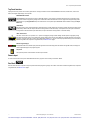
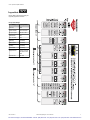
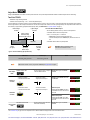
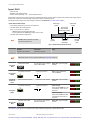
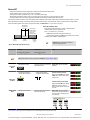
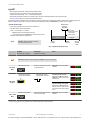
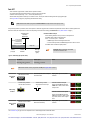
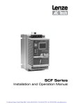
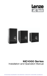
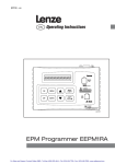
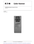
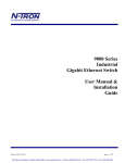
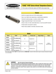
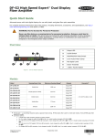
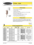
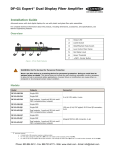
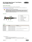
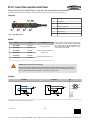
DF-G1 - Expert Fiber Amplifier Install Sheet
Advanced sensor with dual digital displays for use with plastic and glass fiber optic assemblies
For the latest technical information about this product, including specifications, dimensions, and wiring, see www.BannerEngineering.com
Overview
Figure 1. DF-G1 Model Features
1
Output LED
2
LO/DO Switch
3
RUN/PRG/ADJ Mode Switch
4
Lever Action Fiber Clamp
5
Red Signal Level
6
Green Threshold
7
+/SET/- Rocker Button
Models
Model
Outputs
DF-G1-NS-2M
Single NPN
DF-G1-PS-2M
Single PNP
DF-G1-NS-Q3
Single NPN
DF-G1-PS-Q3
Single PNP
DF-G1-NS-Q7
Single NPN
DF-G1-PS-Q7
Single PNP
* Cordset Options: A model with a QD connector requires a
mating cordset. For 9 m cable, change the suffix 2M to 9M in
the 2 m model number (example, DF-G1-NS-9M). For M12
Euro QD pigtail change the suffix 2M to Q5 in the 2 m model
number (example, DF-G1-NS-Q5).
Connector*
2 m (6.5') cable, 4-wire
150 mm (6") PVC pigtail, M8 Pico QD
connector, 4-pin
Integral M8 Pico QD connector, 4-pin
WARNING: Not To Be Used for Personnel Protection
Never use this product as a sensing device for personnel protection. Doing so could lead to serious injury or death. This
product does NOT include the self-checking redundant circuitry necessary to allow its use in personnel safety applications. A sensor
failure or malfunction can cause either an energized or de-energized sensor output condition.
Hookups
NPN Models
PNP Models
Key
2
1
3
4
1 = Brown
2 = White
3 = Blue
4 = Black
For cable options, see http://www.bannerengineering.com
P/N 161275 Rev. A
1/6/2012
0 161275
2
For Sales and Support, Contact Walker EMD • Toll-free: (800) 876-4444 • Tel: (203) 426-7700 • Fax: (203) 426-7800 • www.walkeremd.com
DF-G1 - Expert Fiber Amplifier Install Sheet
Top Panel Interface
Opening the dust cover provides access to the top panel interface. The top panel interface consists of the RUN/PRG/ADJ mode switch, LO/DO switch, +/SET/- rocker
button, dual red/green digital displays, and output LED.
RUN/PRG/ADJ Mode Switch
The RUN/PRG/ADJ mode switch puts the sensor in RUN, PRG (Program), or ADJ (Adjust) mode. RUN mode allows the sensor to operate normally
and prevents unintentional programming changes via the +/SET/- button. PRG mode allows the sensor to be programmed through the display driven
programming menu (see Program Mode below). ADJ mode allows the user to perform Expert TEACH/SET methods and Manual Adjust (see Adjust
Mode below).
LO/DO Switch
The LO/DO switch is used to select Light Operate or Dark Operate mode. In Light Operate mode, the output is ON when the sensing condition is above
the threshold (for Window SET, the output is ON when the sensing condition is inside the window). In Dark Operate mode, the output is ON when the
sensing condition is below the threshold (for Window SET, the output is ON when the sensing condition is outside the window).
+/SET/- Rocker Button
The +/SET/- rocker button is a 3-way button. The +/- positions are engaged by rocking the button left/right. The SET position is engaged by clicking
down the button while the rocker is in the middle position. All three button positions are used during PRG mode to navigate the display driven programming menu. During ADJ mode, SET is used to perform TEACH/SET methods and +/- are used to manually adjust the threshold(s). The rocker button is
disabled during RUN mode, except when using Window SET, see Window SET on page 6 .
Red/Green Digital Displays
During RUN and ADJ mode, the Red display shows the signal level and the Green display shows the threshold. During PRG mode, both displays are
used to navigate the display driven programming menu.
Output LED
The output LED provides a visible indication when the output is activated.
Remote Input
For more information about how to perform TEACH/SET methods and to program the sensor remotely, see the DF-G1 Manual.
Run Mode
Run mode allows the sensor to operate normally and prevents unintentional programming changes. The +/SET/- rocker button is disabled during RUN mode, except when
using Window SET, see Window SET on page 6 .
2
www.bannerengineering.com - tel: 763-544-3164
P/N 161275 Rev. A
For Sales and Support, Contact Walker EMD • Toll-free: (800) 876-4444 • Tel: (203) 426-7700 • Fax: (203) 426-7800 • www.walkeremd.com
DF-G1 - Expert Fiber Amplifier Install Sheet
Program Mode
Program (PRG) mode allows the following settings to be programmed in the DF-G1 :
Factory Default Settings:
Setting
Factory Default
Threshold
2026
TEACH Selection
Two-Point TEACH
Response Speed
Standard - 500 us
Offset Percent
10%
Auto Thresholds
OFF
OFF Delay
0 (Disabled)
OFF One-Shot
0 (Disabled)
ON Delay
0 (Disabled)
ON One-Shot
0 (Disabled)
Display Readout
Numeric, ECO disabled, Normal Orientation
Gain Selection
Auto Gain
P/N 161275 Rev. A
www.bannerengineering.com - tel: 763-544-3164
3
For Sales and Support, Contact Walker EMD • Toll-free: (800) 876-4444 • Tel: (203) 426-7700 • Fax: (203) 426-7800 • www.walkeremd.com
DF-G1 - Expert Fiber Amplifier Install Sheet
Adjust Mode
Sliding the RUN/PRG/ADJ mode switch to the ADJ position allows the user to perform Expert TEACH/SET methods and Manual Adjustment of the threshold(s).
Two-Point TEACH
• Establishes a single switching threshold
• Threshold can be adjusted using “+” and “-” rocker button (Manual Adjust)
Two-Point TEACH is used when two conditions can be presented statically to the sensor. The sensor locates a single sensing threshold (the switchpoint) midway between
the two taught conditions, with the Output ON condition on one side, and the Output OFF condition on the other (see Figure below). The Output ON and OFF conditions can
be reversed by using the LO/DO (Light Operate/ Dark Operate) switch (see LO/DO Switch in Top Panel Interface on page 2).
Darkest Taught
Condition
Two-Point TEACH and Manual Adjust
Lightest Taught
Condition
• Moves switching threshold value up or down to make adjustments
• Slide Mode switch to ADJ to enter Adjust mode
• Press “+” to increase; press “-” to decrease
Sensor positions
threshold midway
between taught conditions
Output OFF
Darkest
(no signal)
• GREEN display shows the switching threshold value
• 2 seconds after adjustment, the GREEN display will flash 3 times to confirm
• Slide Mode switch to RUN to complete operation
Output ON
Position
adjusted by
Manual Adjust
Most Light
(saturated
signal)
Remember: Manual adjustments are disabled when Auto Thresholds are ON
Figure 2. Two-Point TEACH (Light Operate shown)
SET Button
Remote Input
0.04 seconds < "Click" < 0.8 seconds
0.04 seconds < T < 0.8 seconds
Result
Note: TEACH Selection must be programmed to 2Pt tcH (see Program Mode on page 3 )
Set Mode switch to ADJ
Enter Adjust
Mode
TEACH 1st
Condition
• Present 1st condition
• Click the SET rocker button
No action required; sensor is ready for Display: Red - Signal Level; Green Two-Point TEACH method
Threshold
• Present 1st condition
• Single-pulse remote input
Display: Flashes "2Pt tch" then holds
on "1234 2nd"
T
• Present 2nd condition
• Click the SET rocker button
• Present 2nd condition
• Single-pulse remote input
T
TEACH 2nd
Condition
TEACH Accepted
Displays alternate "PASS" and % Minimum Difference*; Sensor returns to Adjust mode
TEACH Unacceptable
Displays alternate "FAIL" and % Minimum Difference*; Sensor returns to Adjust mode
Move Mode switch to RUN
Return to RUN
Mode
No action required; sensor returns to
RUN mode automatically
Display: Red - Signal Level; Green Threshold
* See Troubleshooting on page 10 for more explanation of the % Minimum Difference displayed after the Two-Point TEACH method
4
www.bannerengineering.com - tel: 763-544-3164
P/N 161275 Rev. A
For Sales and Support, Contact Walker EMD • Toll-free: (800) 876-4444 • Tel: (203) 426-7700 • Fax: (203) 426-7800 • www.walkeremd.com
DF-G1 - Expert Fiber Amplifier Install Sheet
Dynamic TEACH
• Teaches on-the-fly
• Establishes a single switching threshold
• Threshold can be adjusted using “+” and “-” rocker button (Manual Adjust)
Dynamic TEACH is best used when a machine or process may not be stopped for teaching. The sensor learns during actual sensing conditions, taking multiple samples of
the light and dark conditions and automatically setting the threshold at the optimum level (see Figure below).
The output ON and OFF conditions can be reversed using the LO/DO switch (see LO/DO Switch in Top Panel Interface on page 2).
Darkest Taught
Condition
Dynamic TEACH and Manual Adjust
• Moves switching threshold value up or down to make adjustments
• Slide Mode switch to ADJ to enter Adjust mode
• Press “+” to increase; press “-” to decrease
Lightest Taught
Condition
Sensor positions
threshold midway
between taught conditions
• GREEN display shows the switching threshold value
• 2 seconds after adjustment, GREEN display will flash 3 times to confirm
• Slide Mode switch to RUN to complete operation
Output OFF
Darkest
(no signal)
Remember: Manual adjustments are disabled
when Auto Thresholds are ON
Output ON
Position
adjusted by
Manual Adjust
Most Light
(saturated
signal)
Figure 3. Dynamic TEACH (Light Operate shown)
SET Button
Remote Input
0.04 seconds < "Click" < 0.8 seconds
0.04 seconds < T < 0.8 seconds
Result
Note: TEACH Selection must be programmed to dYn tcH (see Program Mode on page 3 )
• Set Mode switch to ADJ
Enter Adjust
Mode
• Click the SET rocker button
Enter Dynamic
TEACH
Present ON
and OFF Conditions
No action required; sensor is ready for
Dynamic TEACH method
• Single-pulse remote input
T
Display: Red - Signal Level; Green Threshold
Display: Flashes "dYn tch" then
holds on "1234 dYn"
• Present ON and OFF conditions
• Present ON and OFF conditions
Display: Red - Signal Level; Green Threshold
• Click the SET rocker button
• Single-pulse remote input
TEACH Accepted
T
Exit Dynamic
TEACH
Displays alternate "PASS" with % Minimum Difference*, Sensor returns to
Adjust mode
TEACH Unacceptable
Displays alternate "FAIL" with % Minimum Difference*, Sensor returns to
Adjust mode
• Move Mode switch to RUN
Return to RUN
Mode
No action required; sensor returns to
RUN mode automatically
Display: Red - Signal Level; Green Threshold
* See Troubleshooting on page 10 for more explanation of the % Minimum Difference displayed after the Dynamic TEACH method
P/N 161275 Rev. A
www.bannerengineering.com - tel: 763-544-3164
5
For Sales and Support, Contact Walker EMD • Toll-free: (800) 876-4444 • Tel: (203) 426-7700 • Fax: (203) 426-7800 • www.walkeremd.com
DF-G1 - Expert Fiber Amplifier Install Sheet
Window SET
•
•
•
•
•
Sets window thresholds that extend a programmable % offset above and below the presented condition
All other conditions (lighter or darker) cause the output to change state
Sensing window center can be adjusted using “+” and “-” rocker button (Manual Adjust)
Recommended for applications where a product may not always appear in the same place, or when other signals may appear
See Program Mode in the user's manual for programming the Offset Percent setting (to increase/decrease the window size)
A single sensing condition is presented, and the sensor positions window thresholds a programmable % offset above and below the presented condition. In LO mode,
Window SET designates a sensing window with the Output ON condition inside the window, and the Output OFF conditions outside the window (see Figure below).
Output ON and OFF conditions can be reversed using the LO/DO switch (see LO/DO Switch in Top Panel Interface on page 2).
Sensing window
center adjusted by
Manual Adjust
Output OFF
Darkest
(no signal)
Window SET and Manual Adjust
• Moves sensing window center value up or down to make adjustments
• Slide Mode switch to ADJ to enter Adjust mode
• Press “+” to increase; press “-” to decrease
Sensor positions
window thresholds
a programmable %
offset from the
presented condition
Output ON
• GREEN display shows the sensing window center value
• 2 seconds after adjustment, the GREEN display will flash 3 times to confirm
• Slide Mode switch to RUN to complete operation
Output OFF
Condition
Presented
Most Light
(saturated
signal)
Remember: Manual adjustments are disabled
when Auto Thresholds are ON
Figure 4. Window SET (Light Operate shown)
SET Button
Remote Input
0.04 seconds < "Click" < 0.8 seconds
0.04 seconds < T < 0.8 seconds
Result
Note: TEACH Selection must be programmed to wind SEt (see Program Mode on page 3 )
• Set Mode switch to ADJ
Enter Adjust
Mode
• Present sensing condition
• Click the SET rocker button
No action required; sensor is ready for
Window SET method
• Present sensing condition
• Single-pulse the remote input
T
SET Sensing
Condition
Display: Red - Signal Level; Green Threshold
Threshold Condition Accepted
Displays read "wInd SEt" then alternate
"PASS" with % Offset*; Sensor returns
to Adjust mode
Threshold Condition Unacceptable
Displays read "wInd SEt" then alternate
"FAIL" with minimum % Offset* for
sensing condition; Sensor returns to Adjust mode
Return to RUN
Mode
• Move Mode switch to RUN
No action required; sensor returns to
RUN mode automatically
Display: Red - Signal Level; Green Window Center (see Figure below for instructions on how to display upper and
lower thresholds)
* See Troubleshooting on page 10 for more explanation of the % Offset displayed after the Window SET method
6
www.bannerengineering.com - tel: 763-544-3164
P/N 161275 Rev. A
For Sales and Support, Contact Walker EMD • Toll-free: (800) 876-4444 • Tel: (203) 426-7700 • Fax: (203) 426-7800 • www.walkeremd.com
DF-G1 - Expert Fiber Amplifier Install Sheet
Light SET
•
•
•
•
•
Sets a threshold a programmable % offset below the presented condition
Changes output state on any condition darker than the threshold condition
Threshold can be adjusted using “+” and “-” rocker button (Manual Adjust)
Recommended for applications where only one condition is known, for example a stable light background with varying darker targets
See Program Mode on page 3 for programming the Offset Percent setting
A single sensing condition is presented, and the sensor positions a threshold a programmable % offset below the presented condition. When a condition darker than the
threshold is sensed, the output either turns ON or OFF, depending on the LO/DO switch setting (see LO/DO Switch in Top Panel Interface on page 2).
Threshold position
adjusted by
Manual Adjust
Light SET and Manual Adjust
• Moves switching threshold value up or down to make adjustments
• Slide Mode switch to ADJ to enter Adjust mode
• Press “+” to increase; press “-” to decrease
Sensor positions
threshold a programmable
% offset below the
presented condition
• GREEN display shows the switching threshold value
• 2 seconds after adjustment, the GREEN display will flash 3 times to confirm
• Slide Mode switch to RUN to complete operation
Output OFF
Remember: Manual adjustments are disabled
when Auto Thresholds are ON
Darkest
(no signal)
Output ON
Condition
Presented
Most Light
(saturated
signal)
Figure 5. Light SET (Light Operate shown)
SET Button
Remote Input
0.04 seconds < "Click" < 0.8 seconds
0.04 seconds < T < 0.8 seconds
Result
Note: TEACH Selection must be programmed to Lt SEt (see Program Mode on page 3 )
• Set Mode switch to ADJ
Enter Adjust
Mode
• Present sensing condition
• Click the SET rocker button
No action is required; sensor is ready
for Light SET method
• Present sensing condition
• Single-pulse the remote input
T
SET Sensing
Condition
Display: Red - Signal Level; Green Threshold
Threshold Condition Accepted
Displays read "Lt SEt" then alternate
"PASS" with % Offset*; Sensor returns
to Adjust mode
Threshold Condition Unacceptable
Displays read "Lt SEt" then alternate
FAIL with minimum % Offset* for sensing condition; Sensor returns to Adjust
mode
• Move Mode switch to RUN
Return to RUN
Mode
No action required; sensor returns to
RUN mode automatically
Display: Red - Signal Level; Green Threshold
* Troubleshooting on page 10 for more explanation of the % Offset displayed after the Light SET method
P/N 161275 Rev. A
www.bannerengineering.com - tel: 763-544-3164
7
For Sales and Support, Contact Walker EMD • Toll-free: (800) 876-4444 • Tel: (203) 426-7700 • Fax: (203) 426-7800 • www.walkeremd.com
DF-G1 - Expert Fiber Amplifier Install Sheet
Dark SET
•
•
•
•
•
Sets a threshold a programmable % offset above the presented condition
Any condition lighter than the threshold condition causes the output to change state
Threshold can be adjusted using “+” and “-” rocker button (Manual Adjust)
Recommended for applications where only one condition is known, for example a stable dark background with varying lighter targets
See Program Mode on page 3 for programming the Offset Percent setting
NOTE: Offset Percent MUST be programmed to Minimum Offset to accept conditions of no signal (0 counts).
A single sensing condition is presented, and the sensor positions a threshold a programmable % offset above the presented condition. When a condition lighter than the
threshold is sensed, the output either turns ON or OFF, depending on the LO/DO switch setting (see LO/DO Switch in Top Panel Interface on page 2).
Threshold position
adjusted by
Manual Adjust
Dark SET and Manual Adjust
• Moves switching threshold value up or down to make adjustments
• Slide Mode switch to ADJ to enter Adjust mode
• Press “+” to increase; press “-” to decrease
Sensor positions
threshold a programmable
% offset above the
presented condition
Output OFF
Darkest
(no signal)
• GREEN display shows the switching threshold value
• 2 seconds after adjustment, the GREEN display will flash 3 times to confirm
• Slide Mode switch to RUN to complete operation
Output ON
Condition
Presented
Remember: Manual adjustments are disabled
when Auto Thresholds are ON
Most Light
(saturated
signal)
Figure 6. Dark SET (Light Operate shown)
SET Button
Remote Input
0.04 seconds < "Click" < 0.8 seconds
0.04 seconds < T < 0.8 seconds
Result
Note: TEACH Selection must be programmed to dr SEt (see Program Mode on page 3 )
• Set Mode switch to ADJ
Enter Adjust
Mode
• Present sensing condition
• Click the SET rocker button
No action required; sensor is ready for
Dark SET method
• Present sensing condition
• Single-pulse the remote input
T
SET Sensing
Condition
Display: Red - Signal Level; Green Threshold
Threshold Condition Accepted
Displays read "dr SEt" then alternate
"PASS" with % Offset*; Sensor returns
to Adjust mode
Threshold Condition Unacceptable
Displays read "dr SEt" then alternate
"FAIL" with minimum % Offset* for sensing condition; Sensor returns to Adjust
mode
• Move Mode switch to RUN
Return to RUN
Mode
No action required; sensor returns to
RUN mode automatically
Display: Red - Signal Level; Green Threshold
* See Troubleshooting on page 10 for more explanation of the % Offset displayed after the Dark SET method
8
www.bannerengineering.com - tel: 763-544-3164
P/N 161275 Rev. A
For Sales and Support, Contact Walker EMD • Toll-free: (800) 876-4444 • Tel: (203) 426-7700 • Fax: (203) 426-7800 • www.walkeremd.com
DF-G1 - Expert Fiber Amplifier Install Sheet
Calibration SET
• Sets a threshold exactly at the presented condition
• Threshold can be adjusted using “+” and “-” rocker button (Manual Adjust)
A single sensing condition is presented, and the sensor positions a threshold exactly at the presented condition. When a condition lighter than the threshold is sensed, the
output either turns ON or OFF, depending on the LO/DO switch setting (see LO/DO Switch in Top Panel Interface on page 2).
Threshold position
adjusted by
Manual Adjust
Calibration SET and Manual Adjust
• Moves switching threshold value up or down to make adjustments
• Slide Mode switch to ADJ to enter Adjust mode
• Press “+” to increase; press “-” to decrease
Sensor positions
threshold exactly at
the presented condition
• GREEN display shows the switching threshold value
• 2 seconds after adjustment, the GREEN display will flash 3 times to confirm
• Slide Mode switch to RUN to complete operation
Output OFF
Darkest
(no signal)
Remember: Auto Thresholding is automatically
disabled in Calibration SET
Output ON
Condition
Presented
Most Light
(saturated
signal)
Figure 7. Calibration SET (Light Operate shown)
SET Button
Remote Input
0.04 seconds < "Click" < 0.8 seconds
0.04 seconds < T < 0.8 seconds
Result
Note: TEACH Selection must be programmed to CAL SEt (see Program Mode on page 3 )
• Set Mode switch to ADJ
Enter Adjust
Mode
• Present sensing condition
• Click the SET rocker button
No action required; sensor is ready for
Calibration SET method
• Present sensing condition
• Single-pulse the remote input
T
SET Sensing
Condition
Display: Red - Signal Level; Green Threshold
Threshold Condition Accepted
Displays read "cAL SEt" then flashes
"PASS"; Sensor returns to Adjust
mode
Threshold Condition Unacceptable
Displays read "cAL SEt" then flashes
"FAIL"; Sensor returns to Adjust mode
• Move Mode switch to RUN
Return to RUN
Mode
P/N 161275 Rev. A
No action required; sensor returns to
RUN mode automatically
Display: Red - Signal Level; Green Threshold
www.bannerengineering.com - tel: 763-544-3164
9
For Sales and Support, Contact Walker EMD • Toll-free: (800) 876-4444 • Tel: (203) 426-7700 • Fax: (203) 426-7800 • www.walkeremd.com
DF-G1 - Expert Fiber Amplifier Install Sheet
Troubleshooting
Manual Adjustments Disabled
Manual adjustments are disabled when Auto Thresholds are ON. If a manual adjustment is attempted while Auto Thresholds are ON, the Green display will flash
.
% Minimum Difference after TEACH
The Two-Point and Dynamic TEACH methods will flash a % minimum difference on the displays after a PASS or FAIL.
Value
PASS/FAIL
Description
0-99%
FAIL
The difference of the taught conditions does not meet the required minimum
100-300%
PASS
The difference of the taught conditions just meets/exceeds the required minimum, minor sensing variables may affect
sensing reliability
300-600%
PASS
The difference of the taught conditions sufficiently exceeds the required minimum, minor sensing variables will not affect
sensing reliability
600% +
PASS
The difference of the taught conditions greatly exceeds the required minimum, very stable operation
% Offset after SET
The Window, Dark, and Light SET methods will flash a % offset on the displays after a PASS or FAIL.
SET Result
% Offset Meaning
PASS (with % Offset)
Displays the % offset used for the SET method
FAIL (with % Offset)
Displays the minimum required % offset necessary to PASS the SET method
FAIL (without % Offset)
Presented condition cannot be used for the SET method
Threshold Alert or Threshold Error
Severe contamination/changes in the taught condition can prevent the Auto Thresholds algorithm from optimizing the threshold(s).
State
Display
Description
Corrective Action
Threshold Alert
Alternates
The threshold(s) cannot be optimized, but the
sensor's output will still continue to function
Cleaning/correcting the sensing environment and/or a
re-teach of the sensor is highly recommended
The threshold(s) cannot be optimized, and the
sensor's output will stop functioning
Cleaning/correcting the sensing environment and/or a
re-teach of the sensor is required
and
Threshold Error
Specifications
Sensing Beam
660 nm visible red
Supply Voltage
10 to 30V dc (10% max ripple)
Power and Current Consumption (exclusive of load)
Standard display mode: 960 mW, Current consumption < 40 mA @
24V dc
ECO display mode: 720 mW, Current consumption < 30 mA @ 24V dc
Supply Protection Circuitry
Protected against reverse polarity, over voltage, and transient voltages
Delay at Power Up
500 milliseconds max.; outputs do not conduct during this time
Output Configuration
1 current sourcing (PNP) or 1 current sinking (NPN) output, depending
on model
Output Rating
100 mA max. load (derate 1 mA per °C above 30° C)
OFF-state leakage current: < 5 μA at 30V dc
ON-state saturation voltage: NPN: < 1.5V; PNP: < 2V
Output Protection
Protected against output short-circuit, continuous overload, transient
over-voltages, and false pulse on power up
Output Response Time
High Speed - 200 us; Standard - 500 us; Long Range - 2 ms; Extra Long
Range - 5 ms
Repeatability
High Speed - 66 us, Standard/Long Range/Extra Long Range - 100 us
Construction
Black ABS/polycarbonate alloy (UL94 V-0 rated) housing, clear polycarbonate cover
Environmental Rating
IEC IP50, NEMA 1
Operating Conditions
Temperature: -10° to +55° C (+14° to 131° F)
Storage: -20° to +85° C (-4° to +185° F)
Relative Humidity: 90% @ 60° C (non-condensing)
Certifications
Warranty: Banner Engineering Corporation warrants its products to be free from defects for a period of one
year. Banner Engineering Corporation will repair or replace, free of charge, any product of its manufacture
found to be defective at the time it is returned to the factory during the warranty period. This warranty does not
cover damage or liability for the improper application or installation of Banner products. This warranty is in lieu
of any other warranty either expressed or implied.
For Sales and Support, Contact Walker EMD • Toll-free: (800) 876-4444 • Tel: (203) 426-7700 • Fax: (203) 426-7800 • www.walkeremd.com