1
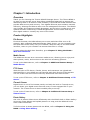
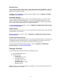
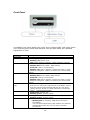
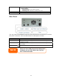
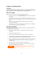
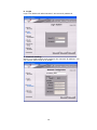
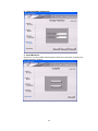
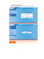
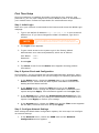
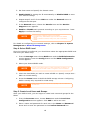
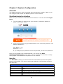
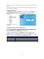
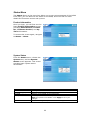
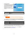
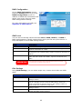
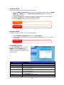
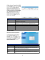
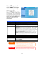
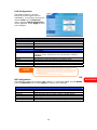
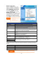
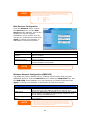
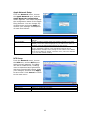
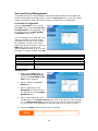
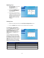
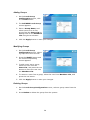
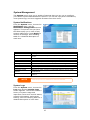
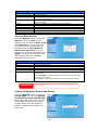
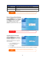
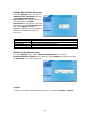
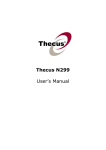
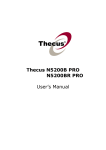
Thecus N299
User’s Manual
Copyright and Trademark Notice
Thecus and other names of Thecus products are registered trademarks of Thecus
Technology Corp. Microsoft, Windows, and the Windows logo are registered
trademarks of Microsoft Corporation. Apple, iTunes and Apple OS X are registered
trademarks of Apple Computers, Inc. All other trademarks and brand names are
the property of their respective owners. Specifications are subject to change
without notice.
Copyright © 2007 Thecus Technology Corporation. All rights reserved.
About This Manual
All information in this manual has been carefully verified to ensure its correctness.
In case of an error, please provide us with your feedback. Thecus Technology
Corporation reserves the right to modify the contents of this manual without
notice.
Product name: Thecus N299
Manual Version: 1.1
Release Date: November 2007
Limited Warranty
Thecus Technology Corporation guarantees all components of Thecus N299 are
thoroughly tested before they leave the factory and should function normally
under general usage. In case of any system malfunctions, Thecus Technology
Corporation and its local representatives and dealers are responsible for repair
without cost to the customer if the product fails within the warranty period and
under normal usage. Thecus Technology Corporation is not responsible for any
damage or loss of data deemed to be caused by its products. It is highly
recommended that users conduct necessary back-up practices.
2
Chapter 1: Introduction
Overview
Thank you for choosing the Thecus N299 IP Storage Server. The Thecus N299 is
an easy-to-use storage server that allows a dedicated approach to storing and
distributing data on a network. Data reliability is ensured with RAID features that
provide data security and recovery. Two Gigabit Ethernet ports enhance network
efficiency, allowing the N299 to take over file management functions. The N299’s
user-friendly GUI supports multiple languages, and its built-in media server and
optional wireless connectivity via USB dongles allow users to share and enjoy
their digital media in virtually any room of the house.
Product Highlights
File Server
First and foremost, the N299 allows you to store and share files over an IP
network. With a Network Attached Storage (NAS) device, you can centralize your
files and share them easily over your network. With the easy-to-use web-based
interface, users on your network can access these files in a snap.
To learn about the Web User Interface, go to Chapter 5: Using the N299 >
Web User Interface.
Media Server
The N299 can also act as a convenient media server, allowing you to enjoy and
share photos, music, and movies via the uPnP AV streaming protocol.
To set up the Media Server, refer to Chapter 4: Additional Feature Setup >
Media Server.
FTP Server
With the built-in FTP Server, friends, clients, and customers can upload and
download files to your N299 over the Internet with their favorite FTP programs.
You can create user accounts so that only authorized users have access.
To set up the FTP Server, refer to Chapter 4: Additional Feature Setup > FTP
Server.
iTunes® Server
Digital music is one of the hottest trends, and with the built-in iTunes® server,
you can share your digital music files with every iTunes-equipped PC on your
network. The iTunes Server is also incredibly easy to set up!
To set up the iTunes Server, refer to Chapter 4: Additional Feature Setup >
iTunes Server.
Photo Gallery
Got a lot of photos? Share them effortlessly with the N299’s built-in Photo Gallery.
Users can create albums and upload photos in a snap, and the N299 will even
auto-create thumbnails.
To find out how to share photos with the N299, refer to Chapter 5: Using the
N299 > Using Photo Gallery.
8
Backup Server
Don’t leave precious data to chance. With advanced backup capabilities, you can
easily upload mission critical files to the N299, and even automate your backup
tasks for true peace-of-mind.
To find out how to backup your files with the N299, refer to Chapter 5: Using
the N299 > File Backup.
Download Manager
Tired having downloads take up all of your bandwidth when you need it most?
With the N299’s Download Manager, you can let the N299 complete your BT,
HTTP, and FTP during off-peak hours. With the N299 lower power requirements,
you can even save money off your monthly power bill.
To set up the Download Station, refer to Chapter 4: Additional Feature Setup
> Download Manager.
Printer Server
With the N299’s Printer Server, you can easily share an IPP printer with other PCs
connected to your network.
To set up the Printer Server, refer to Chapter 4: Additional Feature Setup >
Printer Server.
IP Cam Surveillence Server
Keep an eye on things with the built-in IP Cam Surveillence Server. Just plug in a
compatible webcam and the N299 can send snapshots to an account that you
specify. Best of all, your PC doesn’t even have to be turned on!
To set up the IP Cam Surveillence Server, refer to Chapter 4: Additional
Feature Setup > IP Cam Surveillence.
Package Contents
Your N299 package should contain the following items:
•
•
Thecus N299 NAS Device
Accessory Pack:
o Power cord
o RJ-45 Ethernet cable
o hard disk screws
o hard disk tray screws
o Installation CD
o Quick Installation Guide
o Warranty card
Please check to see if your package is complete. If you find that some items are
missing, contact your dealer.
9
Front Panel
The N299’s front panel displays the unit’s array of status LEDs, and is also where
you’ll find the power button and USB port. See the table below for a detailed
explanation of each:
Item
Power LED
System Status LED
HDD1 LED
HDD2 LED
One-Button USB
Copy
WAN LED
LAN LED
USB LED
Description
• Solid blue: N299 is powered on
• Blinking orange: system is starting up
• Blinking red: system error
• Off: system startup complete; system operating normally
• Solid blue: HDD 1 detected
• Blinking blue: Active HDD 1 data transfer
• Solid red : HDD 1 error detected
• Blinking red: HDD 1 capacity is nearly full (90% or more)
* If RAID is configured, capacity is based on the entire RAID
system.
• Solid blue: HDD 2 detected
• Blinking blue: Active HDD 2 data transfer
• Solid red : HDD 2 error detected
• Blinking red: HDD 2 capacity is nearly full (90% or more)
* If RAID is configured, capacity is based on the entire RAID
system.
• One-Button Copy
Push once to copy entire USB volume to the N299. A short
beep will sound to acknowledge that files are now being
copied. Files are stored in a folder named by current time
stamp: (YearMonthDayHHMM)
• Solid green: network link
• Blinking green: network activity
• Solid green: network link
• Blinking green: network activity
• USB Device Connection
o Blinking blue (5 seconds): USB device connected
successfully.
*For universal USB memory card readers, the USB LED
will blink blue when one or more card is mounted
successfully.
10
o Blinking red (5 seconds): USB device connection failure
• Data Transfer
USB Port
Power Button
o Blinking blue: Active data transfer
o Blinking red: USB device read/write error
• USB 2.0 port for USB storage expansion.
• Power on/off N299
Rear Panel
The rear panel of the N299 houses the USB and Ethernet connections, as well as
the power connector. See the table below for descriptions of each:
Item
Power Connector
WAN Port
LAN Port
USB Ports
NOTE
Description
• Connect the included power cord to this connector
• WAN port for connecting to an Ethernet network through a
switch or router
• LAN port for connecting to an Ethernet network through a switch
or router
• USB 2.0 ports for storage expansion
There are two USB ports at the back panel
of N299, you can use either one, but not
two at the same time.
11
Chapter 2: Getting Started
Overview
Your N299 is designed for complete ease-of-use. To help you get started, the
following chapter will help you get your N299 up and running in no time. Please
read it carefully to prevent damaging your unit during installation.
Before You Begin
Before you begin, be sure to take the following precautions:
1. Read and understand the Safety Warnings outlined in the beginning of
the manual.
2. If possible, wear an anti-static wrist strap during installation to prevent
static discharge from damaging the sensitive electronic components on the
N299.
3. Be careful not to use magnetized screwdrivers around the N299’s
electronic components.
4. The N299 uses its chassis to dissipate heat. Please leave your N299 in a
well-ventilated area to prevent overheating.
Hard Disk Installation
The N299 supports standard 3.5” (SATA) hard disks. To install a hard disk into
the N299, follow the steps below:
1. Remove two screws located on the back of the unit using a Philips
screwdriver.
2. Unscrew four mounting screws.
3. Lift up the hard disk tray by pulling up the top panel of the N299.
4. Carefully insert a standard 3.5” SATA hard disk into the tray, and secure
the hard disk with screws from the included accessory pack.
5. If you are installing two hard disks, please insert the second hard disk at
the bottom of the tray and secure it with screws from the included
accessory pack.
6. Carefully lower the hard disk tray back into the N299.
7. After making sure the tray is in place and the connectors are aligned,
secure the hard disk tray with screws.
NOTE
If your hard disk was previously part of a RAID 1 array, it will automatically rebuild.
If you replace all the drives with higher capacity drives, you need to go to the
Administrator login and format the drives.
12
Cable Connections
Make the following connections on the Thecus N299 and then power up the unit:
1. Connect an Ethernet cable from your network to the WAN port on the
back panel of the N299.
2. Connect the provided power cord into the universal power socket on the
back panel. Plug the other end of the cord into a surge protected socket.
3. Press the power button on the front panel to power on the N299.
4. Make sure system is running properly by checking all front panel LEDs for
any error indications.
Installation Wizard
The handy Thecus Setup Wizard makes configuring N299 a snap. To configure the
N299 using the Setup Wizard, perform the following steps:
1. Insert the installation CD into your CD-ROM drive (the host PC must be
connected to the network).
2. The Setup Wizard should launch automatically. If not, please browse your
CD-ROM drive and double click on Setup.exe.
NOTE
For MAC OS X users, double click on Thecus Setup Wizard 1.1.6.dmg
3. Complete the Setup Wizard
a. Device Discovery
The Setup Wizard will start and automatically detect all Thecus Storage
devices on your network.
13
b. Login
Login into N299 with administrator’s account and password.
c. Network Setting
Name your N299 system and configure the network IP address. You
can choose either fixed IP or DHCP.
14
d. Change Admin Password
e. Start Browser
Access the current N299 administrator Web User Interface pressing the
“Start Browser” button.
15
f. RAID and FW installation
Please config the RAID first then carry on with FW installation to
complete setup procedure.
NOTE
The Thecus Setup Wizard is designed for installation on systems running Windows
XP/2000 or Mac OSX or later. Users with other operating systems will need to install
the Thecus Setup Wizard on a host machine with one of these operating systems
before using the unit.
16
First Time Setup
Once the hardware is installed, physically connected to your network, and
powered on, you can now configure the Thecus N299 so that it is accessible to
your network users. Follow the steps below for initial software setup.
Step 1: Initial Login
Make sure your network is connected to the Internet and access the N299 Login
webpage:
1. Type in the default IP address http://192.168.1.100 in your browser’s
address line. If you have changed the N299’s IP address, type this in
instead.
NOTE
To access any IP address, your computer must be configured with the correct IP
settings. The IP address should be 192.168.1.x, where x is a number between 1 and
254.
2. The Login screen appears.
3. To gain initial access to the system type in the factory default
administrator user name and password, which are as follows:
User Name:
Password:
admin
admin
4. Press Login.
5. The About screen from the Status menu appears showing product
information.
Step 2: System Check and Configuration
Once logged in, you are greeted with the Web Administration Interface, where
you can check the N299’s status, as well as configure its operating parameters.
1. In the Status menu, choose the System item to go to the System
Status screen. Check that the basic system information such as CPU
loading and Fan RPM are all OK.
2. In the Status menu, choose the Info item to go to the System
Information screen. Change the System Description to describe your
system and press Apply. This information appears on the Login page.
3. In the System menu, choose the Administrator Password item. The
screen that appears lets you change the administrator password for the
system. Press Apply to confirm your settings.
4. In the System menu, choose the Time item and the Time screen appears.
Set the date, time and time zone and press Apply.
Step 3: Configure Network Settings
After setting the N299’s basic configuration options, the next step is to configure
its network settings.
1. In the Network menu, choose the WAN item and the Network
Configuration screen appears.
17
2. Set host name and specify the domain name.
3. Enable DHCP for setting the IP automatically or Disable DHCP to enter
your own IP settings.
4. Repeat steps 2 and 3 for the LAN item under the Network menu to
configure the LAN port.
5. In the Network menu, choose the Service item and the Service
Support screen appears.
6. Enable or Disable each protocol according to your requirements. Press
Apply to confirm the setting.
NOTE
• For normal usage, enabling all protocols is recommended.
• For added security, disable WebDisk support and enable Secure WebDisk
support.
• If DHCP is enabled in the Network Settings screen, UPnP is automatically
enabled.
For details on configuring your network settings, refer to Chapter 3: System
Management > Network Management.
Step 4: Select RAID Level
Once the network is configured, you should then select the appropriate RAID level
and build your RAID array.
1. From the Storage menu choose RAID item and the RAID Information
screen appears. Press the Config button and the RAID Configuration
screen appears.
2. Select your desired RAID mode.
NOTE
If security is your primary concern, for 2 disks, choose RAID 1. If capacity is your
primary concern, choose JBOD or RAID 0. See Appendix C for more information.
3. Check the hard disks you wish to create a RAID on. Specify a stripe size—
64K is a normal setting.
4. Press the Create button to build the RAID storage volume. Configuring
RAID is usually only required for initial setup.
NOTE
Building a RAID storage space may take time, depending on the size of hard drives
and RAID mode.
Step 5: Create Local Users and Groups
After your RAID is built, you can begin to create local users and groups for the
N299.
1. From the Accounts menu, choose Users item and the Local User
Configuration screen appears. Click Add to add a new user.
2. Enter a name and password for each user in the Name and Password
boxes and re-enter the password in the Confirm Password box.
18
3. Press the Apply button for each user and they will be added to the user
list.
4. From the Accounts menu, choose Groups item and the Local Group
Configuration screen appears. Click Add to add a new group.
5. Enter a group name in the Group Name box and click Apply to add the
group to the group list.
For more on managing users, go to Chapter 3: System Management > User
and Group Management.
Step 6: Create Folders and Set Up ACLs
Once users are introduced into your network, you can begin to create various
folders on the N299 and control user access to each using Folder Access Control
Lists.
1. From the Storage menu, choose the Folder item and the Folder screen
appears. Press the Add button and the Add Folder screen appears.
2. Enter the name and description of the folder and choose whether it is
browseable. Press Apply to create the folder.
3. On the Folder screen press ACL (Access Control List) to configure which
users have access to this folder.
4. On this screen, configure access to this folder for users and groups. Select
a user or a group from the left hand column and then choose Deny
Access, Read Only, or Writable to configure their access level. Press
Apply to confirm settings.
NOTE
You must set the ACL for each folder for access by specific users and groups;
otherwise the folder is inaccessible to all users and groups.
For more information on managing folders, see Chapter 3: System
Management > Storage Management > Folder Management.
To find out about configuring Folder Access Control Lists, see Chapter 3: System
Management > Storage Management > Folder Management > Folder
Access Control List (ACL).
Step 7: Start Services
Finally, you can start to setup the different services of the N299 for the users on
your network. You can find out more about each of these services by clicking
below:
Windows Networking
Apple File Protocol (AFP)
FTP Server
iTunes® Server
Photo Gallery
Media Server
Download Manager
Printer Server
IP Cam Surveillance Server
19
Chapter 3: System Configuration
Overview
The N299 provides an easily accessible web management interface. With it, you
can configure and monitor the N299 anywhere on the network.
Web Administration Interface
Make sure your network is connected to the Internet. To access the N299 Login
Page:
1. Type the N299’s IP address into your browser. (Default IP address is
http://192.168.1.100)
Your computer’s network IP address must be on the same subnet as the N299. If
the N299 has default IP address of 192.168.1.100, your managing PC IP address
must be 192.168.1.x, where x is a number between 1 and 254, but not 100.
NOTE
2. Login to the system using the administrator user name and password. The
factory defaults are:
User Name: admin
Password: admin
If you changed your password in the setup wizard, use the new password.
Once you are logged in as an administrator, you will see the Web
Administration Interface. From here, you can configure and monitor virtually
every aspect of the N299 from anywhere on the network.
Menu Bar
The Menu Bar is where you will find all of the information screens and system
settings of the N299. The various settings are placed in the following groups on
the menu bar:
Menu Bar
Item
Status
Storage
Network
Accounts
System
Language
Description
Current system status of the N299.
Information and settings for storage devices installed into the
N299.
Information and settings for network connections and services,
as well as various services of the N299.
Allows configuration of users and groups.
Various N299 system settings and information.
Choose your preferred language here.
20
Clicking on any of these items will display the dropdown menu selections for each
group.
In the following sections, you will find detailed explanations of each function, and
how to configure your N299.
Language Selection
The N299 supports multiple languages. On the menu bar, click Language and
the Change Language screen appears. This screen allows you to select
preferred language for the N299. The N299’s interface supports the following
languages:
•
•
•
•
•
•
•
•
•
English
Simplified Chinese
Traditional Chinese
German
French
Italian
Japanese
Korean
Spanish
Press Apply to confirm your
selection.
Language Package Upload and Management
You can also upload additional language packs as they become available. To do
this, press Upload and the Language Package Upload/Management and
User Upload Language Package List screens appear.
To upload a language package, click Browse and browse for the language
package location. Select the language package file and click Open. Then, click
Apply to upload the language package to the N299. Once uploaded, the language
package will appear in the User Upload Language Package List.
User Upload Language Package List
Item
Description
Product
Name of language package.
Version
Language package version number.
Description
Language package description.
Remove Package
Click Remove to remove the selected language package.
21
Status Menu
The Status Menu on the menu bar allows you to see various aspects of the N299.
From here, you can discover the status of the N299, and even find out other
details like firmware version and up time.
Product Information
Once you login, you will first see the
basic Product Information screen
providing Manufacturer, Product
No., Firmware Version, and Up
Time information.
To access this screen again, navigate
to Status > About.
System Status
From the Status menu, choose the
System item, and the System
Status screen appears. This screen
provides basic system status
information.
System Status
Item
CPU Loading (%)
Fan RPM
Fan Speed Control
Up Time
Description
Displays current CPU workload of the N299.
Displays current RPM of the internal fan.
You may select a desired fan speed from here. Normal and
High fan speeds are available. Click Apply to save your
changes.
Shows how long the system has been running.
22
System Information
From Status menu, choose the Info
item, and the System Information
screen appears. You can change the
system information that appears on
uPnP devices screens (i.e. Network
Neighborhood) on Windows-based
systems by entering the new
information here and pressing Apply
to confirm.
System Information
Item
System Description
Description
Shows the system description that would also appear on the
Login page.
Printer Status
NOTE
In order to use the Printer Server, you must first install the Printer Server module
located on the installation CD. Once installed, the Printer Status option will appear
on the Main Menu. See Chapter 4: Additional Feature Setup > Print Server for more
details.
From the Status menu, choose the Printer item, and the Printer Information
screen appears. The Printer Information screen provides the following information
about the USB printer connected to the USB port.
Printer Information
Item
Manufacturer
Model
Status
Printer Queue
Description
Displays the name of the USB printer manufacturer.
Displays the model of the USB printer.
Displays the status of the USB printer.
Click to remove all documents from printer queue
If a corrupt print job is sent to a printer, printing may suddenly fail. If your print
jobs seem to be locked up, pressing the Remove All Documents button to clear
the print queue may resolve the issue.
For information on how to set up the Printer Server, refer to Chapter 4:
Additional Feature Setup > Printer Server.
23
Storage Management
The Storage Menu displays the status of storage devices installed or connected
to the N299, including disk and RAID information.
Disk Information
From the Storage menu, choose the
Disks item and the Disk
Information screen appears. From
here, you can see various items
about installed SATA hard disks.
Blank lines indicate that a SATA hard
disk is not currently installed in that
particular disk slot.
SATA Information
Item
Disk Slot
Capacity (MB)
Model
Firmware
Status
Total
File System Check
NOTE
Description
Indicates disk location.
Shows the SATA hard disk capacity.
Displays the SATA hard disk model name.
Shows the SATA hard disk firmware version.
Indicates the status of the disk. Can read OK, Warning, or Failed.
Shows the total SATA hard disk capacity.
Click Apply to run a file system check on installed hard disks.
Some services will scan the content directories, and this will keep the hard disk
drive from spinning down.
RAID Information
From the Storage menu, choose the
RAID item and the RAID
Information screen appears.
RAID Information
Item
RAID Level
Total Capacity
Status
Used Percentage
Stripe Size
Remaining Time
Description
Shows the current RAID configuration.
Shows total capacity of the RAID configuration.
Indicates status of the RAID. Can read either Healthy or Failed.
Displays percentage of used RAID capacity.
Shows the current disk stripe size.
Indicates time remaining until the RAID is finished building.
To configure your RAID settings, press the Config button to go to the RAID
Configuration screen.
24
RAID Configuration
On the RAID Information screen,
press the Config button to go to the
RAID Configuration screen. In
addition to RAID disk information and
status, this screen lets you make
RAID configuration settings.
For more information on RAID, see
Appendix C: RAID Basics.
RAID Level
You can set the storage volume as either None, JBOD, RAID 0, or RAID 1.
RAID configuration is usually required only when you first set up the device. A
brief description of each RAID setting follows:
RAID Levels
Level
None
JBOD
RAID 0
RAID 1
WARNING
Description
There is no existing storage volume.
The storage volume is a single HDD with no RAID support. JBOD
requires a minimum of 1 disk.
Provides data striping but no redundancy. Improves
performance but not data safety. RAID 0 requires a minimum of
2 disks.
Offers disk mirroring. Provides twice the read rate of single
disks, but same write rate. RAID 1 requires a minimum of 2
disks.
If the administrator improperly removes a hard disk that should not be removed
when RAID status is degraded, all data will be lost.
Disk Settings
Using Disk Settings, you can select stripe size, choose which disks are RAID
disks.
Disk Settings
Item
RAID
Stripe Size
Create RAID
Remove
Description
Check the boxes of the hard drives you wish to add to the
storage volume.
This sets the stripe size to maximize performance of sequential
files in a storage volume. Keep the 64K setting unless you
require a special file storage layout in the storage volume. A
larger stripe size is better for large files.
Press this button to configure a file system and create the RAID
storage volume.
Click to remove the RAID volume. All user data, snapshot, and
Target USB data will be removed.
25
Creating a RAID
To create a RAID volume, follow the steps below:
1. On the RAID Configuration screen, set the RAID storage space as JBOD,
RAID 0, or RAID 1 — see Appendix C: RAID Basics for a detailed
description of each.
2. Tick the checkboxes of the hard disks you wish to use to create a RAID.
3. Specify a stripe size — 64K is the default setting.
4. Press Create to build the RAID storage volume.
NOTE
WARNING
Building a RAID storage space may take time, depending on the size of hard drives
and RAID mode.
Creating RAID destroys all data in the current RAID. The data is unrecoverable.
Deleting a RAID
To delete a RAID volume, follow the steps below:
1. On the RAID Configuration screen, click Remove.
2. The system automatically removes the RAID volume and you can create a
new RAID.
WARNING
Removing RAID destroys all data in the current RAID. The data is unrecoverable.
Folder Management
From the Storage menu, choose
Folder, and the Folder screen
appears. This screen allows you to
create and configure folders on the
N299 volume.
Folder
Item
Folder name
Description
NFS
ACL
Edit
Del
Remove
Add
Description
Displays the name of the folder.
Provides a description of the folder.
Press NFS to setup access privilege.
Press ACL (Access Control List) to configure which users have
access to this folder.
Press Edit to enter the Edit screen and modify the folder’s
name and description.
Press Del to delete the folder. A screen appears asking to
confirm the deletion.
Press Remove to delete folder.
Press Add to enter the Add Folder screen.
26
Adding Folders
On the Folder screen, press the Add
button and the Add Folder screen
appears. This screen allows you to
add a folder. After entering the
information, press Apply to create
new folder. Press Back to return to
the Folder screen.
Add Folder
Item
Folder Name
Description
Browseable
Public
Web Access
Apply
Reset
NOTE
Description
Enter the name of the folder.
Provide a description the folder.
Enable users to browse the folder content.
Admit or deny public access to this folder.
Admin or deny access through web disk.
Press Apply to create the folder.
Press Reset to clear entered data.
Folder names are limited to 60 characters. Systems running Windows 98 or earlier
may not support file names longer than 15 characters.
Editing Folders
On the Folder screen, press the Edit
button and the Edit Folder screen
appears. This screen allows you to
change folder information. After
entering the information, press
Apply to apply the changes. Press
Back to return to the Folder screen.
Edit Folder
Item
Description
Browseable
Public
Web Access
Apply
Cancel
Back
Description
Provide a description the folder.
Enable users to browse the folder content.
Admit or deny public access to this folder.
Admin or deny access through web disk.
Press Apply to save your changes.
Press Cancel to disregard entered data
Press Back to return to upper page.
Deleting Folders
To delete a folder, press the Del button from the specified folder row. The system
will confirm folder deletion. Press OK to delete the folder permanently or Cancel
to go back to the folder list.
WARNING
All the data stored in the folder will be deleted once the folder is deleted. The data
will not be recoverable.
27
Folder Access Control List (ACL)
On the Folder screen, press the ACL
button, and the Folder Access
Control List (Folder ACL) screen
appears. This screen allows you to
configure access to the specific folder
for users and groups. Use the Read
only, Writable, Deny access, or
Unset radio buttons to configure
access levels for listed users and
groups. Press the Apply button to
confirm your settings.
Folder ACL
Item
Folder
Recursive
Local Groups/Local
Users
Read Only
Writable
Deny
Unset
Apply
Cancel
Back
Description
Current folder name
Check this box if you want your settings to also apply for all
subfolders in current folder.
Names of local groups and local users. Local groups are
displayed in red, while local users are displayed in green.
Provides Read Only access to users or groups.
Provides Write access to users or groups.
Denies access to users or groups.
Resets current user’s/group’s access privilages.
Click Apply to save your changes.
Click Cancel to exit without saving changes.
Click Back to return to the Folder screen.
Service Folders
The N299 automatically creates
folders for its built-in applications.
To manage these service folders,
select Service Folder from the
Storage menu. Press NFS to setup
access privilege. Press Edit to edit
these folders. Press ACL to control
access to these folders via the
Access Control List.
Service Folders
Folder Name
Photos
Video
Music
USBCopy
USBHDD
IPCam
Description
Default directory for your photos.
Default directory for your video files.
Music for the iTunes Server is located here. The iTunes server will
share the music located in this directory.
Contents copied from the One-Touch USB Copy function are stored
here.
Contents copied from USB hard disks are stored here.
Stored still frames from the Simple Surveillance Server are stored
here.
28
Network Management
Use the Network menu to make
network configuration settings as
well as service support settings.
WAN Configuration
From the Network menu, choose
WAN, and the WAN Configuration
screen appears. This screen displays
the network parameters of the WAN
connection. You may change any of
these items and press Apply to
confirm your settings. You can see a
description of each item in the
following table:
WAN Configuration
Item
Host name
Domain name
MAC Address
Jumbo Frame Support
Connection Type
User Name
Password
IP
Netmask
DNS Server
IP Sharing Mode
PPPoE Connect
Description
Host name that identifies the N299 on the network.
Specifies the domain name of the N299.
Display the WAN port MAC address.
Enable or disable Jumbo Frame Support of the WAN interface on
your N299.
The WAN IP can be set to a Static IP, Dynamic IP, or PPPoE.
Static: Administrator has to enter IP, Netmask, Gateway, DNS
Server fields.
Dynamic: If there is already a DHCP server on your network,
you can let the DHCP server assign an IP address to your N299.
NOTE: If this is set to Dynamic, but a DHCP server is not
detected on the WAN network, the IP address of the N299 will
reset to the default setting of 192.168.1.100.
PPPoE: The N299 can also support a direct connection to an
ASDL modem through PPPoE. Once selected, you will need to
enter a User Name and Password.
Enter your user name for PPPoE connection. (PPPoE only)
Enter your password for PPPoE connection. (PPPoE only)
IP address of the WAN interface.
Network mask, which is generally: 255.255.255.0
Domain Name Service (DNS) server IP address.
When enabled, traffic on the LAN will be directed to the WAN.
Default is Disabled.
Connect or disconnect from a PPPoE connection. (PPPoE only)
NOTE
• Only use Jumbo Frame settings when operating in a Gigabit environment where
all other clients have Jumbo Frame Setting enabled.
• Enabling DHCP automatically turns on UPnP — See the Service Support
Screen.
• If you are only using the WAN port, we suggest that you disable IP Sharing
Mode. This will result in higher throughput.
• A correct DNS setting is vital to networks services, such as SMTP and NTP.
WARNING
Most Fast Ethernet (10/100) Switches/Routers do not support Jumbo Frame and
you will not be able to connect to your N299 after Jumbo Frame is turned on. If this
happens, turn off the N299. Then, power on the N299 and immediately press and
hold the Reset button on the front of the unit for 10 seconds. This will reset your
network settings, password, and turn off Jumbo Frame Support.
29
LAN Configuration
The N299 supports a second
Ethernet port for higher service
availability. To configure these ports,
choose LAN from the Network
menu, and the LAN Configuration
screen appears. Press Apply to save
your changes.
LAN Configuration
Item
Description
MAC Address
Displays the MAC address of the LAN interface.
Jumbo Frame Support
Enable or disable Jumbo Frame Support on the LAN interface.
IP
Specifies the IP address of the LAN interface.
Netmask
Specifies the Network Mask of the LAN interface.
DHCP Server Configuration
Item
Description
DHCP Server
Enable or disable the DHCP server to automatically assign IP
addresses to PCs connected to the LAN interface. Default is
Disabled.
Start IP
Specifies the starting IP address of the DHCP range.
End IP
Specifies the ending IP address of the DHCP range.
DNS Server
Specifies the DNS server IP address.
Apply
Click Apply to save your changes.
Cancel
Click Cancel to abandon your changes.
NOTE
• Before enabling Jumbo Frame Support, please make sure your network
equipment supports Jumbo Frame. If your equipment is incompatible, you might
not be able to connect to your N299. In this case, you have to reset the system
back to default by the holding down front panel reset button for 5 seconds
during boot up process.
• The IP Segment of WAN and LAN should not overlap.
DD
WARNING
NS Configuration
The N299 also features Dynamic DNS support. To configure DDNS, choose DDNS
from the Network menu. Press Apply to confirm your settings.
DDNS Support
Item
Register
User Name
Password
Domain Name
Apply
Cancel
Description
Support www.dyndns.org, www.zoneedit.com, www.tzo.com
Input user name that you have register in DDNS domain.
Input password that you have register in DDNS domain.
Input registered domain name.
Click Apply to save your changes.
Input Click Cancel to abandon your changes.
30
WLAN Configuration
When a compatible wireless USB
dongle is installed on the N299, the
N299 will become an access point,
and the Network dropdown menu
will contain a WLAN menu item.
From the Network menu, choose
WLAN, and the WLAN
Configuration screen appears. This
screen displays the wireless network
parameters of the system. You can
to change any of these items and
press Apply to confirm your settings.
• Currently supported USB wireless
dongles are: 3Com
3CRUSB10075, Zyxel G220USB,
PCI GW-US54mini.
• USB dongles have to be connected
before N299 is powered up.
NOTE
WLAN Configuration
Item
MAC Address
IP
Netmask
ESSID
ESSID Broadcast
Channel
Auth Mode
WEP Enable
Key Length
WEP
WEP
WEP
WEP
KEY
KEY
KEY
KEY
1
2
3
4
Description
Displays the MAC Address of the USB wireless dongle.
Specifies the IP address of the network connection.
Specifies the network mask, which is generally: 255.255.255.0
The ESSID (Extended Service Set Identification) is the
identifying name of a wireless network.
Specifies whether the ESSID will be broadcasted by the N299.
This will prevent the Access Point from broadcasting the ESSID.
The N299 will still respond to a wireless device that LAN1ts to
communicate if it sends a matching ESSID.
The channel that the N299 uses to communicate with client
devices.
Authentication mode used by the N299.
Shared: Shared key authentication
Open: Open key authentication
Specifies whether to use encryption for transmission or not.
Key length specifies the level of encryption used by the N299.
64 bit: 10 characters from 0 ~ 9 and A ~ F.
128 bit: 26 characters from 0 ~ 9 and A ~ F.
Input up to 4 WEP keys, and select the one you wish to use.
When connecting, be sure to enter the same key and select the
same index number on each client machine.
A DHCP server can be configured to assign IP addresses to wirelessly connected
devices.
WLAN DHCP Configuration
Item
Description
DHCP Server
Select to enable or disable DHCP server.
Start IP
Specifies the starting IP address of the DHCP range.
End IP
Specifies the ending IP address of the DHCP range.
DNS Server
Specifies the DNS server IP address.
NOTE
The IP Segment of WLAN, WAN and LAN should not overlap.
31
NOTE
Users should obey the international RF regulatory rules as they set up the wireless
RF channel on the N299. The RF operating channels for different regions have
been specified as following. Thecus has no responsibility for users attempting to
violate the international RF regulation.
11
14
13
2
4
N. America
Japan
Europe (ETSI)
Spain
France
Web Services Configuration
From the Network menu, choose
the Services item, and the Web
Service screen appears. This screen
displays the service support
parameters of the system. You can
change any of these items and press
Apply to confirm your settings. A
description of each item follows:
Web Service
Item
HTTP (WebDisk)
Support
HTTPs (Secure
WebDisk) Support
UPnP
NOTE
Description
Enable or disable WebDisk support. Enter the port number if this
option is enabled.
Enable or disable Secure WebDisk support. Enter the port if this
option is enabled.
Enable or disable Universal Plug and Play protocol. UPnP helps to
find the IP address of the N299.
Disable HTTP support and Enable Secure HTTP support to guarantee secure access.
Windows Network Configuration (SMB/CIFS)
The N299 can act as a Samba server, enabling users to share files using the
SMB/CIFS protocol. From the Network menu, choose the SMB/CIFS item, and
the SMB/CIFS screen appears. You can change any of these items and press
Apply to confirm your settings. A description of each item follows:
SMB/CIFS
Item
Sharing
WINS Server
Work Group / Domain
Name
NOTE
Description
If you are using Microsoft Windows®, enable this service to
access the files on the N299 by mapping a network drive.
Specify the WINS server IP address, if your network has a WINS
server installed. The N299 will automatically register its name
and IP address with WINS service.
Enable or disable SMB/CIFS protocol for Windows, Apple, Unix
drive mapping.
• SMB/CIFS service also allows file sharing from Mac OSX and Linux platforms.
• Once a Mac OS accesses a share folder, it will create a file named .DS_Store,
and directories named Temporary items, Network Trash Folder, .Apple Double,
Apple Desktop and AppleDB in the share folder.
32
Apple Network Setup
From the Network menu, choose
the Apple Network item, and the
Apple Network Configuration
screen appears. This screen displays
the configuration items for the Apple
Filing Protocol. You can change any
of these items and press Apply to
confirm your settings. A description
of each item follows:
Apple Network Configuration
Item
Description
Apple File Service
Enable Apple File Service to use the N299 on MAC OS-based
system.
MAC CHARSET
If your operating system does not support Unicode (e.g. MAC
OS9/8), select the same language as your OS here in order to
properly view the files and directories on the server.
Zone
Specifies Zone for Applet Talk service.
If your AppleTalk network uses extended networks and is
assigned with multiple zones, assign a zone name to the N299.
If you do not Want to assign a network zone, enter an asterisk
(*) to use the default setting.
NFS Setup
From the Network menu, choose
the NFS item, and the NFS server
setting screen appears. The N299
can act as a NFS server, enabling
users to download and upload files
with their favorite NFS clients. Make
your changes, and then click Apply
to save them. Click Cancel to return
to the main menu.
NFS
Item
NFS Service
Network Interface
Description
Enable or disable NFS support
Select the network interface for NFS service.
33
User and Group Management
The N299 has built-in user database that allows administrators to manage user
access using different group policies. From the Accounts menu, you can create,
modify, and delete users, and assign them to groups that you designate.
Local User Configuration
From the Accounts menu, choose
the Users item, and the Local User
Configuration screen appears. This
screen allows you to Add, Modify,
and Delete local users.
You can quickly find a particular user
name by clicking one of the letter
groupings at the top of the window.
For example, to find a user name
beginning with the letter M, click the
MNO user group, and the user
names beginning with M, N, or O will
be listed. To see all names, click ALL.
Local User Configuration
Item
Description
User Name
Current user name.
Group
Group membership of current user name.
Add
Press the Add button to add a user to the list of local users.
Modify
Press the Modify button to modify a local user.
Delete
Press the Delete button to delete a selected user from the
system.
Adding Users
1. Click on the Add button on
Local User Configuration
screen, and Add NEW Local
User screen appears.
2. Enter a name in the User
Name box.
3. Enter a password in the
Password box and re-enter
the password in the Confirm
Password box.
4. Select which group the user
will belong to. The Owner Group list is a list of groups this user belongs
to. The Unjoined Group list is a list of groups this user does not belong
to. Use the << or >> buttons to have this user join or leave a group.
5. Press the Apply button and the user is created.
NOTE
All users are automatically assigned to the ‘users’ group.
34
Modifying Users
1. Select an existing user from
the Local User
Configuration screen.
2. Click on the Modify button,
and Local User Setting
screen appears.
3. From here, you can enter a
new password and re-enter to
confirm, or use the << or >>
buttons to have this user join
or leave a group. Click the
Apply button to save your
changes.
Deleting Users
1. Select an existing user from the Local User Configuration screen.
2. Click on Delete button and the user is deleted from the system.
Local Groups Configuration
From the Accounts menu, choose
the Groups item, and the Local
Group Configuration screen
appears. This screen allows you to
Add, Modify, and Delete local
groups.
You can quickly find a particular
group by clicking one of the letter
groupings at the top of the window.
For example, to find a user name
beginning with the letter M, click the
DEF letter group, and the groups
beginning with M, N, or O will be
listed. To see all groups, click ALL.
Local Groups Configuration
Item
Description
Group Name
Current group name.
User
Users currently in current group.
Add
Press the Add button to add a user to the list of local groups.
Modify
Press the Modify button to delete a selected group from the
system.
Delete
Press the Delete button to delete a selected group from the
system.
35
Adding Groups
1. On the Local Group
Configuration screen, click
on the Add button.
2. The Add NEW Local Group
screen appears.
3. Enter a Group Name, and
select users to be in this
group from the Users List by
adding them to the Members
List using the << button.
4. Click the Apply button to save your changes.
Modifying Groups
1. On the Local Group
Configuration screen, select
a group name from the list.
2. Press the Modify button and
the Local Group Setting
screen appears.
3. To add a user into a group,
select the user from the
Users List, and press the <<
button to move the user into
the Members List.
4. To remove a user from a group, select the user from Members List, and
press the >> button.
5. Click the Apply button to save your changes.
Deleting Groups
1. On the Local Group Configuration screen, select a group name from the
list.
2. Press Delete to delete the group from the system.
36
System Management
The System menu gives you a wealth of settings that you can use to configure
your N299’s system administration functions. You can set up system notifications,
view system logs, and even upgrade firmware from this menu.
System Notifications
From the System menu, choose the
Notification item, and the
Notification Configuration screen
appears. This screen lets you have
the N299 notify you in case of any
system malfunction. Press Apply to
confirm all settings. See following
table for a detailed description of
each item.
Notification Configuration
Item
Description
Beep Notification
Enable or disable the system beeper that beeps when a problem
occurs.
Email Notification
Enable or disable email notifications of system problems.
SMTP Server
Specifies the hostname/IP address of the SMTP server.
Port
Specifies the port to send outgoing notification emails.
Auth Type
Select the SMTP Server account authentication type.
Sender Address
Set the sender mail address.
Sender Password
Enter the password for the sender’s mail account.
Confirm Password
Confirm a new password.
Receivers’ E-mail
Add one or more recipient’s email addresses to receive email
Address
notifications.
Send Test Mail
Click to send out a test e-mail to make sure the settings are
correct.
NOTE
Consult with your mail server administrator for email server information.
System Logs
From the System menu, choose the
Logs item and the System Logs
screen appears. This screen shows a
history of system usage and
important events such as disk status,
network information, and system
booting. See the following table for a
detailed description of each item:
37
System Logs
Item
Truncate All Log File
|<< < > >>|
INFO
WARN
ERROR
GO
Ascending
Descending
Download All Log File
Description
Clear all log files.
Use the forward ( > >>| ) and backward ( |<< < ) buttons
to browse the log pages.
Provides all log information including warning messages and
error messages.
Shows all warning messages and error messages.
Shows only error messages.
Specify the number of lines per page and press Go.
Shows logs by date in ascending order.
Shows logs by date in descending order.
Export all logs to an external file.
Time and Date Settings
From the System menu, choose the
Time item and the Time screen
appears. Set the desired Date, Time,
and Time Zone. You can also elect
to synchronize the system time on
the N299 with an NTP (Network
Time Protocol) Server. You can
change any of these items and press
Apply to confirm your settings. See
the following table for a detailed
description of each item:
Time
Item
Date
Time
Area
City
NTP Server
WARNING
Description
Sets the system date.
Sets the system time.
Select your area.
Select your city.
Select Yes to allow the N299 to synchronize with the NTP server
shown below.
Select Maually to allow the N299 to synchronize with an NTP
server of your choice.
Select No to not have the N299 to synchronize with an NTP
server.
If an NTP server is selected, please make sure your N299’s network has been setup
to access the NTP server.
System Configuration Backup and Restore
From the System menu, choose the
Config Mgmt item and the System
Configuration Download/Upload
screen appears. From here, you can
download or upload stored system
configurations. See the following
table for a detailed description of
each item.
38
System Configuration
Item
Download
Browse
Upload
NOTE
Download/Upload
Description
Save and export the current system configuration.
Click to browse the folder of your PC to locate the configuration
files.
Import a saved configuration file to overwrite current system
configuration.
Backing up your system configuration is a great way to ensure that you can revert
to a working configuration when you are experimenting with new system settings.
Reset to Factory Default Settings
From the System menu, choose the
Factory Default item and the Reset
to Factory Default screen appears.
Press Apply to reset the N299 to
factory default settings. Press
Cancel to go back to the main menu.
WARNING
Resetting to factory defaults will not erase the data stored in the hard disks, but
WILL revert all the settings to the factory default values.
Upgrading System Firmware
From the System menu, choose the
Firmware Upgrade item and the
Firmware Upgrade screen appears.
Follow the steps below to upgrade
your firmware:
1. Use the Browse button to
find the firmware file.
2. Press Apply.
3. The beeper beeps and the Busy LED blinks until the upgrade is complete.
NOTE
• The beeper only beeps if it is enabled in the System Notification menu.
• Check Thecus website for the latest firmware release and release notes.
39
Change Administrator Password
From the System menu, choose the
Administrator Password item and
the Change Administrator
Password screen appears. Enter a
new password in the New
Password box and confirm your new
password in the Confirm Password
box. Press Apply to confirm
password changes. See the following
table for a detailed description of
each item.
Change Administrator
Item
Old Password
New Password
Confirm Password
Apply
Password
Description
Type in the current administrator password.
Type in a new administrator password.
Type the new password again to confirm.
Press this to save your changes.
Reboot and Shutdown System
From the System menu, choose Reboot & Shutdown item, and the
Shutdown/Reboot System screen appears. Press Reboot to restart the system
or Shutdown to turn the system off.
Logout
To logout of the Web Administration Interface, navigate to System > Logout.
40