1
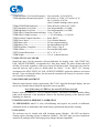
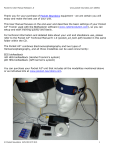
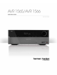
USER’S MANUAL FOR THE GENERAL DEVICES MULTI-LEAD MODEL EIM-107 PREP-CHECK PLUS™ ELECTRODE IMPEDANCE METER FOR POLYSOMNOGRAPHY & EEG Doc. #: 1078002x CONTROLLED Revision: H TABLE OF CONTENTS 1 GENERAL INFORMATION ........................................................................... 1 1.1 OVERVIEW OF USER’S MANUAL 1.2 CAUTIONARY NOTICES 2 PRODUCT INTRODUCTION ......................................................................... 1 2.1 PRODUCT DESCRIPTION 2.2 APPLICATIONS 2.3 PRODUCT FEATURES 2.4 OPTIONS AND ACCESSORIES 3 CONNECTION TO EQUIPMENT ................................................................... 3 4 OPERATION ...................................................................................................... 4 4.1 A QUICK GUIDE TO OPERATION 4.2 DESCRIPTION OF CONTROLS AND INDICATORS 4.3 DETAILED OPERATING INSTRUCTIONS 5 SETTING USER-SELECTABLE FEATURES .............................................. 6 5.1 OVERVIEW 5.2 FRONT PANEL USER-SETTINGS 5.3 EZ-SET PC SOFTWARE USER-SETTINGS 6 TROUBLESHOOTING GUIDE FOR ELECTRODE PROBLEMS ........... 9 7 TECHNICAL INFORMATION, SERVICE AND MAINTENANCE .......... 10 7.1 GLOSSARY OF TERMS 7.2 PRODUCT SPECIFICATIONS 7.3 SELF-TEST/CAL FAILURE 7.4 BATTERY REPLACEMENT 7.5 MAINTENANCE & PERIODIC CALIBRATION 7.6 CLEANING 7.7 SERVICING 8 PRODUCT WARRANTEE AND SERVICE ................................................... 12 8.1 WARRANTY TERMS AND CONDITIONS 8.2 NON-WARRANTY SERVICE 8.3 FACTORY TECH SUPPORT HOURS 8.4 RETURNING GOODS TO FACTORY 9 FIGURES AND DRAWINGS ........................................................................... 13 9.1 Figure 9.1: DIMENSIONS AND PHYSICAL CHARACTERISTICS 9.2 Figure 9.2: CONNECTING PREP-CHECK PLUS™ TO PC SERIAL PORT 9.3 Figure 9.3: EZ-SET PROGRAMMING SCREEN 10 ADDENDUM ..................................................................................................... 15 1 1 GENERAL INFORMATION 1.1 OVERVIEW OF USER’S MANUAL This manual provides operating, programming, troubleshooting and service information for the General Devices' EIM-107 PREP-CHECK PLUS™ multi-lead electrode impedance meter for polysomnography and EEG electrode assessment. An addendum page is included to accommodate special instructions for certain units. 1.2 CAUTIONARY NOTICES 1.2.1 This product must be used in accordance with the instructions provided with this manual. To maintain the manufacturer’s warrantee and insure safe operation, under no circumstances is the device to be opened or modified without the express written consent of General Devices. 1.2.2 Check ADDENDUM page for special instructions for certain units 1.2.3 Do not allow fluids to enter instrument. 1.2.4 Do not submerge instrument in fluids of any kind. 1.2.5 Do not use the instrument should it in any way appear to malfunction. 1.2.6 Do not connect the instrument to a patient while programming with the EZ-Set software. 1.2.7 All lead wires and cables providing direct connection between this device and the patient must comply with FDA Performance Standard 21 CFR Part 898. Consult your lead wire/cable supplier or manufacturer to insure proper compliance. 2 PRODUCT INTRODUCTION 2.1 PRODUCT DESCRIPTION The PREP-CHECK PLUS™ is a compact, battery powered hand-held meter used to measure the electrical impedance and offset voltage of bio-potential electrodes for polysomnography and other, similar applications. Many features are user-defined, enhancing speed and convenience. The EZSet programming option permits fast and easy user “customization”, further enhancing the instruments utility. The meter is self-testing and self-calibrating, insuring reliable, accurate readings. Measurement data as well as operating cues are presented on a large illuminated alphanumerical readout with interpretation assisted by color-coded “GOOD” and “POOR” lamps as well as audible cues. Lead selection is either manual or automatic, with several methods of response to bad or suspect leads. Special features permit quick identification of intermittent lead wires. Impedance measurements are made between the selected electrode and all other electrodes, simplifying the identification of problem electrodes, electrode sites and lead wires. A front panel mounted connector provides connection to the headbox. Many automatic and user-settable features simplify operation. The PREP-CHECK PLUS™ is housed in a compact, ergonomically designed, impact resistant, flame-retardant ABS-plastic enclosure. The instrument is powered by long-lasting, common AA 2 batteries. Battery life is enhanced by an Auto-Off feature, which eliminates the possibility of accidentally leaving the instrument on when not in use. See figure 9.1 for dimensions and other physical characteristics. 2.2 APPLICATIONS 2.2.1 The PREP-CHECK PLUS™ tests all types of surface type biopotential electrodes used for sleep studies and EEG. Testing all electrodes for impedance insures minimal motion and 60 Hz. artifact and disruption to the study. Although some instruments possess internal impedance measurement capabilities, oftentimes the readout displays are located in the monitoring areas, distant from the patient’s bedside. The use of a hand-held, stand-alone impedance meter permits fast, accurate bedside assessment of electrode performance in a convenient, economical way. Specifically designed for this application, the unit even has a softly lit display, permitting operation in a dimly lit room. 2.3 PRODUCT FEATURES The PREP-CHECK PLUS™ possesses many important and unique features designed to save time and simplify electrode testing. These include: Fast, accurate impedance and offset voltage readings Quick identification of faulty lead wires Large, illuminated alpha-numeric display, flashing color-coded LEDS and audible cues specifically designed for extreme ease of use and rapid electrode assessment Automatic self-test/auto-calibration for reliability of reading Manual or automatic test modes User-selectable GOOD/POOR criterion User-settable “Skip-Lead” feature to remove unused leads from testing sequence Two user-selectable strategies to assess and correct electrode problem User-selectable test current frequency EZ-Set PC Software option for fast, simplified user customization Long lasting inexpensive batteries with battery life enhanced by Auto-Off feature Compact, lightweight, easy to hold rugged cabinet 2.4 OPTIONS AND ACESSORIES EZ-SET PC SOFTWARE: Additional features for customized operation are available with the EZ-Set PC software (See Section 5.3). 3 CONNECTION TO EQUIPMENT The PREP-CHECK PLUS™ is provided with: For most EEG applications, a variety of multi-pin connector types are available to mate with different equipment types. Contact General Devices for specific information. For polysomnography applications, a model is available with twenty (20), 0.060” “safety DIN” connectors. These mates with most standard electrode lead wires. Adapters are available to permit mating with older 0.080” pin-jack connectors however, these adapters are very unreliable and should be used with caution. Note: Should it be necessary to use lead 3 identification names OTHER than those on this unit’s front panel, labels with other names may be placed over the front panel and the unit rep-programmed to reflect these new names on the LCD readout (See Section 5 “SETTING USER-SELECTABLE FEATURES”). 4 OPERATION IMPORTANT!! The PREP-CHECK PLUS™ possesses many user-selectable features. To insure a better understanding of these features and the ways they may be best employed to satisfy the unique needs of each user, it is advisable that Section 5 “SETTING USER-SELECTABLE FEATURES” be reviewed prior to operating the instrument. A QUICK GUIDE TO OPERATION In AUTOMATIC mode, the PREP-CHECK PLUS™ is operated as follows: Connect the instrument to the desired electrodes. Press the START key. The unit will indicate “SELF-TEST, PLEASE WAIT”. After several seconds “BATT OK/Cal OK” appears and is ready for use. Press the START key a second time. The instrument will sequentially test all the non-skipped electrodes. The conclusion of the test sequence is indicated in the display by “TEST COMPLETED” and, 1 long beep and “TEST OK” if all electrodes are GOOD OR: 5 short beeps and displays “XX LEADS FAILED PRESS UP DOWN KEYS TO VIEW POOR LEADS”. Failed leads are viewed and re-tested using the UP and DOWN keys. Each failed electrode may be corrected at this time OR the overall results may be reviewed to determine if the problem is common to many electrodes, such as will occur with a bad batch of electrodes or an unconnected cable. The instrument will automatically turn itself off after the programmed time interval. MANUAL & DC OFFSET VOLTAGE modes operate in the same manner, except that the UP/DOWN keys are used to select the electrodes and the readings are continuous until a new electrode is selected. 4.1 DESCRIPTION OF CONTROLS AND INDICATORS This section describes the PREP-CHECK PLUS™’s control keys, readouts and audible alerts. 4.1.1 START KEY: The start key is used to: Turn the instrument on Initiate an automatic testing sequence Immediately return to the beginning of the test sequence It is also used in programming as described in the programming section. 4 4.1.2 MODE KEY The mode key is used to select manual test, automatic test, DC Offset voltage measurement, or programming mode. 4.1.3 UP & DOWN KEYS The up & down keys are used to increment and decrement electrode selection to the next or previous (non-skipped) electrode. It is also used in programming as described in the programming section. 4.1.4 LCD READOUT The LCD readout is used to indicate the: Number and user-defined name of the electrode being measured Impedance and offset voltage reading of the electrode being measured Pass/Fail (good/poor) status of the electrode being measured Result of the automatic self-test/auto-cal process Status of the battery End of the automatic test sequence It is also used in programming as described in the programming section. 4.1.5 GOOD/POOR LIGHTS The GOOD/POOR lights are used to indicate the pass/fail impedance measurement status. The lights also respond to intermittent lead and electrode conditions. The red (or yellow) POOR light flashes when the impedance value is equal to or exceeds the poor limit setting. The POOR light will also respond to intermittent lead breaks that may not appear on the numerical impedance readout. The green GOOD light flashes when the impedance value is equal to or less than the good limit setting. 4.1.6 AUDIBLE TONE The audible tone is used to alert the user as follows: 3 short beeps: A FAIL in Automatic or Manual which is NOT intermittent 3 long beeps: An intermittent FAIL in Automatic or Manual 1 long beep: The end of an AUTOMATIC test sequence WITH NO failed leads 5 short beeps: The end of an AUTOMATIC test sequence WITH failed leads 1 long beep: The end of a PASSED self-test/auto cal 5 short beeps: The end of a FAILED self-test/auto cal 5 4.2 DETAILED OPERATING INSTRUCTIONS This section provides more detailed operating instructions. Connections to equipment, complete descriptions of controls, indicators and terminology are provided in other parts of this manual. START-UP OPERATIONS Whenever the unit powers-up (goes from OFF to ON), it automatically performs a battery check, a self-test of its circuits as well as a complete re-calibration. Upon passing these tests, the display reads “BATT OK/CAL OK” and is accompanied by one long beep sound. Should it fail any of these checks, refer to Section 7, “Service and Maintenance” for instructions. After the start-up checks, the unit assumes the NORMAL operating mode (manual, automatic or last used mode, as determined by user-selected setting) (See Section 5). 4.2.1 OPERATING MODES Pressing the MODE key permits selecting an operating mode other than the present operating mode OR putting the unit into the PROGRAMMING mode. To better understand the unit’s operation, Section 5, “Setting User Selectable Features” should be reviewed for a list of the operating features that are factory or front panel user-selectable and features available using the EZ-Set PC Software Option. 4.2.2 MANUAL MODE IMPEDANCE MEASUREMENTS In the MANUAL MODE, leads are selected using the UP & DOWN keys. The unit will skip leads that have been identified (marked) as unused. Pass/Fail indication is determined in accordance with the Fail Criterion (See Section 5.2.3.5) and is indicated on the LCD, the GOOD/POOR lamps, and by audible sounds. Impedance readings are continuous for as long as the lead is selected. This mode is useful for troubleshooting or for testing lead wires. Pressing the START key re-starts the test sequence. 4.2.3 AUTOMATIC MODE IMPEDANCE MEASUREMENTS In AUTOMATIC MODE, all non-skipped leads are automatically, sequentially selected. The unit’s response to electrodes meeting the failure criterion/failure (FAIL RESPONSE) is user selectable (See Sect. 5). With the FAIL RESPONSE set to “STOP”, the unit will: issue 3 short beeps on each failed lead; stop; and read continuously until the test is resumed by pressing the START key. While testing, pressing the START key at any time will stop testing. A second press of the START key returns the unit to the beginning of the test sequence. With the FAIL RESPONSE set to “COMPLETE”, the test sequence will be completed without stopping for failed leads. Completion of the test sequence is announced by 1 long beep and the legends: “TEST COMPLETE: ALL LEADS OK” if all leads are good OR 5 short beeps, OR, “TEST COMPLETE: XX LEADS FAILED” if any leads failed. The failed leads may be retested by using the UP/DOWN keys. During re-test, the reading is continuous. Press the START key at any time to start the test sequence. 6 4.2.4 TESTING INTERMITTENT LEADS If the meter encounters an intermittent lead (See Section 7.1.5) the instrument will issue three long beeps and INTERMITTANT is displayed on the LCD. Test the suspect lead wire by lightly pulling on it from both ends. If the lead wire is bad, it will read “OVER RANGE” and light the RED (or yellow) “POOR LED”. Defective wires should be immediately discarded! 4.2.5 DC OFFSET MEASUREMENT In the DC OFFSET MODE, the DC Offset voltage of each lead is measured. The leads are selected using the UP and DOWN keys. Pressing the START key at any time returns the unit to the start of the test sequence (the first non-skipped lead). 4.2.6 PROGRAMMING MODE Without the EZ-Set option, skipped leads may be marked as described in Section 5.1.2. With the EZ-Set option, a wide variety of customized features may be set as described in Section 5.2. 4.2.7 AUTO-OFF After a period of time AFTER the last front panel control operation OR after the conclusion of a test sequence, the unit will automatically turn itself off. This time period may be set as described in Sect. 5.3.3.3. 5 SETTING USER-SELECTABLE FEATURES The PREP-CHECK PLUS is a microprocessor-controlled device with many programmable features. As shown in the following table, some of these features are factory set, some front-panel userdefined, and most user-defined with the EZ-Set PC Software LISTING OF PROGRAMMABLE FEATURES Feature Skip-Lead ------------------------Failure Criterion ----------------Failure Response ----------------Normal Start-Up Mode --------GOOD/POOR Limits ----------Auto-Off Timeout Setting ------Test Current Frequency --------Lead Identification Name ------- Default Setting Front Panel N/A Yes Greater Than Poor No Complete No Last Used No 10 K/15 K No 2 minutes No 30 Hz No None No EZ-Set Yes Yes Yes Yes Yes Yes Yes Yes 5.1 FRONT PANEL USER-SETTINGS 5.1.1 SETTING MANUAL/AUTOMATIC TEST MODES: Press the START key to turn instrument on. After the unit has completed the automatic self-test/auto-calibration, press the MODE key and select either MANUAL or AUTOMATIC. Press the START key to resume normal operation. 7 5.1.2 MARKING LEADS TO BE SKIPPED. After start-up, press the MODE key until the readout indicates PROGRAM. The readout will then display the programming instructions in scrolling fashion. Use the UP/DOWN keys to select the lead to be skipped. Mark the lead to be skipped by pressing the START key. Continue for all leads to be marked. Leads may be unmarked by the same process. Press the MODE key to return to normal operation. 5.2 EZ-SET PC SOFTWARE USER-SETTINGS With the EZ-Set PC Software Option, the PREP-CHECK PLUS™ Electrode Impedance Meter may be quickly and easily programmed using any standard PC with Microsoft Windows 7 & 8 and a standard serial port (See Figure 9.2). The EZ-Set Option includes an EZ-Set Interconnect Cable, which plugs into the computer’s serial port (COM 1, 2 etc.) and into the programming jack on the underside of the instrument. Caution! Do not connect the PREP-CHECK PLUS™ to a patient while programming with the EZ-Set software. 5.3 INSTALLING THE EZ-SET PROGRAMMING SOFTWARE IN YOUR PC 5.3.1.1 Visit the GD website, “Product Support” tab, search for devices specific section and download install file “EZ-Set” 5.3.1.2 Select RUN (on the monitor screen’s pop-up dialog box) Follow the instructions that then appear on the monitor screen. 5.3.2 CONNECTING THE PC TO THE PREP-CHECK PLUS™ (SEE FIGURE 9.2) 5.3.2.1 Locate the EZ-Set Programming Cable 5.3.2.2 Connect the EZ-Set cable to the PC’s 9-pin serial connector. Note: If your PC does not have a 9-pin connector, conversion adapters are commonly available. 5.3.2.3 Plug the EZ-Set cable’s programming jack (2.5 mm jack) into the PREP-CHECK PLUSTM 5.3.3 PROGRAMMING THE PREP-CHECK PLUS™ To begin program the PREP-CHECK PLUS™, select EZ-Set from Start menu. The programming screen will appear as shown in Figure 9.3. Enter User-setting information into each screen entry box as follows: 8 5.3.3.1 LEAD INFORMATION Each lead may be assigned a user-defined name in addition to the lead number (the lead number relates the lead to its position on the front panel). A name may consist of any combination of up to 8 characters (letters, numbers, or spaces). Leads which are unused may be removed (skipped) from the test sequence. Unless skipped unused leads will always appear as failed leads, increasing test time and making troubleshooting more difficult. Leads are marked to be skipped by selecting the desired lead on the screen and pressing the LEFT mouse key. A check mark will appear in the SKIP LEAD box. Once marked as SKIPPED, that lead will not appear in either the manual or the automatic test sequence. The skip-lead feature is also programmable from the front panel keys. 5.3.3.2 TEST CURRENT FREQUENCY Typical EEG test frequency is 20 or 30 Hz, but 30 Hz is recommended. The recommended test frequency for ECG is 10 Hz. 5.3.3.3 AUTO-OFF TIME-OUT The instrument will automatically turn itself off after the last control key operation OR the conclusion of an automatic test sequence. The time period is determined by the AUTO-OFF TIME-OUT period setting. The Auto-Off Time-out may be set between 10 to 2,550 seconds, in 10-second increments. 5.3.3.4 GOOD/POOR LIMITS The GOOD/POOR limits may be set for values between 1K and 100K in 100 Ohm steps. The limits are not permitted to overlap (i.e., the POOR limit may not be set at a lower value than the GOOD limit. The limits are set in accordance with the criterion established for your organization or for particular applications. 5.3.3.5 FAILURES & FAILURE RESPONSE FAILURE CRITERION refers to classifying failures as either IMPEDANCE GREATER than the POOR limit OR IMPEDANCE GREATER than the GOOD limit. For questionable electrodes, it may be desirable to have a separation between the two limits. FAILURE RESPONSE refers to how the instrument responds to failures in the automatic test mode. The PREP-CHECK PLUS™ may be set to manage failed leads in either of two ways: STOP: Unit stops and beeps on each failed lead CONTINUE: The unit will beep on each failed lead (to advise the user of problems), but will not stop until the end of the test sequence. Failed leads are presented at the conclusion of the test sequence, when they then can be examined and corrected. 5.3.3.6 DEVICE INFORMATION Firmware Rev: Displays the revision number for each particular unit. This number may be useful for troubleshooting purposes. Unit’s Serial Number: Displays the unit’s serial number 9 Connection Setup: Used to select the PC’s Com Port (i.e., Com 1, Com 2, etc.) 5.3.3.7 START-UP MODE The START-UP Mode setting permits the unit to return to the PRESET operating mode upon start-up OR to the LAST USED setting. For example, if the unit is normally used in the Automatic mode, and it is only occasionally used in the Manual mode or for DC Offset testing, it may be desirable for it to always start in Automatic, with the other uses selected as needed. Selecting Auto, Manual, DC Offset, or Last Used determines the mode the unit will next start up in. 5.3.3.8 PREP-CHECK This box relates to actions involving the instrument (WRITING the user-selections TO the instrument OR READING existing settings FROM the instrument. Selecting the WRITE TO box, passes screen information to the instrument. Selecting the READ FROM box, passes information stored within the instrument connected to the PC to the PC’s screen. 5.3.3.9 FILE This box relates to actions involving the computer files containing the user-selected operating characteristics. Files may be either 1) WRITTEN TO from the display screen, or 2) READ FROM an existing file stored within the computer. Selecting the WRITE TO box stores screen information to a file named in a “SAVE AS” popup dialog box, which automatically appears. The file name is saved with a “.prp” suffix. That file may be stored anywhere within the computer. To aide retrieval, it is recommended that the files be stored in a folder named “PREP_CHECK”. Selecting the READ FROM box presents information stored in a file selected from an “OPEN” pop-up dialog box that appears automatically. These files represent previously saved instrument settings. 5.3.3.10 QUIT The QUIT box is selected to exit the EZ-Set program and return to other PC operations. Information that is present on the screen will be lost unless previously saved to a file. 6 TROUBLESHOOTING GUIDE FOR ELECTRODE PROBLEMS At times it is difficult to identify the source of a high impedance reading or electrode problem as the problem may be related to: the prep; the lead wires; connectors, cables and adapters; the electrodes; or the meter. Each of these elements has to be addressed separately. To identify the source of a problem, perform the following steps in the order indicated: 10 6.1 METER VERIFICATION The meter is tested and calibrated each time it is turned on. If the meter does not turn on at all, try replacing the batteries. To verify that is OK while in use, allow the instrument to turn itself off, and then turn it back on. If it passes the self-test/auto-calibration it should be operating properly. Should the meter fail to pass these checks, refer to Section 7 “Service and Maintenance” for instructions. 6.2 CONNECTORS, CABLES AND ADAPTER CHECKS Connectors, cables and adapters are KNOWN to be a prime source of problems, particularly intermittent problems (See Sections 7.1.5 & 4.2.4, “Testing Intermittent Leads”). Verify that all such elements are properly connected and replace with known good ones whenever possible. 6.3 LEAD WIRE CHECKS Lead wires are frequent sources of problems, particularly intermittent ones (See Sections 7.1.5 & 4.2.4, “Testing Intermittent Leads”). Test lead wires by touching the electrodes (or lead wire ends) together and checking for impedance less than 100 ohms. Defective lead wires should be immediately discarded to avoid future difficulties. 6.4 ELECTRODE CHECKS Electrodes are checked in much the same way as lead wires (touching them together -- impedance below 100 ohms). Should the readings be higher than expected, this should be discussed with your electrode supplier. 6.5 ELECTRODE SITE PREPARATION Improper electrode site preparation is the most common cause of problems. To perform a good site preparation, use only material specifically intended for this purpose. Be sure the materials are used in accordance with the directions supplied by the manufacturer. If all preceding problem sources have been ruled out, the most likely source of the problem is the prep procedure or the materials used. This should be discussed with your supplier of prepping agents or electrodes. Our web site at www.prepcheck.com provides a list of some suppliers of these agents. 7 TECHNICAL INFORMATION, SERVICE AND MAINTENANCE 7.1 GLOSSARY OF TERMS 7.1.1 IMPEDANCE & KOHMS The unit of measurement that describes the quality of the electrical connection of a bio-potential electrode to a patient is IMPEDANCE, which is expressed in OHMS. Impedance is the degree of opposition to the flow of electricity. It differs from RESISTANCE in that impedance is used for AC measurements whereas resistance is used for DC measurements. The higher the impedance, the poorer the connection. Most biopotential electrode impedances are normally in the 2 to 15 thousand-ohm range, and are thus expressed in thousands of ohms, or Kilo-Ohms (KOhms). 7.1.2 SKIPPED ELECTRODE The PREP-CHECK PLUS™ has the ability to skip over user-specified electrodes in both manual and automatic testing modes. For example, if the lead connected to the CHIN2 jack were not 11 used, the instrument would be instructed not to test that lead. This feature saves time and simplifies the testing procedure, since unused electrodes do not appear as failed electrodes. The term SKIP is used throughout this manual and also appears in the LCD during the programming sequence. 7.1.3 TEST CURRENT AND TEST CURRENT FREQUENCY Testing electrodes requires the use of a TEST CURRENT. The PREP-CHECK PLUS™ employs a sinusoidal ALTERNATING CURRENT (AC), as opposed to DIRECT CURRENT (DC), which may create DC OFFSET VOLTAGES. The TEST CURRENT FREQUENCY refers to the number of cycles per seconds, expressed as HERTZ (Hz.). 20 and 30 Hz are the generally accepted frequencies for EEG, with 10 Hz generally accepted for ECG. Readings vary slightly with different test frequencies. For most applications the difference will not interfere with the intended task of the instrument. 7.1.4 DC OFFSET VOLTAGE The DC OFFSET VOLTAGE of an electrode is a polarizing voltage produced by the electrode and the electrolyte gel or paste. Offset voltages are at the milli-volt (mV) level and may interfere with measurements or produce artifact. Electrodes must be handled in accordance with the electrode’s manufacturer instructions to avoid offset voltage -- refer to the instructions for the electrodes being used regarding care and handling. 7.1.5 INTERMITTENT PROBLEMS Lead wires tend to fail over time. When they simply “open” (i.e., the conductor breaks) the wire will not conduct the signal and its resistance (impedance) will be very high (infinite). At times, lead wires become “intermittent”, that is, they do not “open” permanently. Intermittents tend to “come and go” usually as the wires are moved, producing an unstable or “noisy” signal. Intermittents are difficult to troubleshoot because the problem may not exhibit at the time the wire is tested. An intermittent wire will usually fail with slight pulling from both ends during testing. 7.2 PRODUCT SPECIFICATIONS 7.2.1 Measurements Performed -------------7.2.2 # Electrodes Tested: --------------------7.2.3 Electrode Selection: --------------------7.2.4 Electrode/Headbox Connection: ------- Impedance & Offset Voltage 20 Automatic or manual Twenty 0.060” shrouded “safety DIN” jacks OR Multi-pin connector 7.2.5 Self-Test & Calibration ---------------- Self-Test & Cal, Automatic on start 7.2.6 Primary Display: ------------------------- Back-lit 0.4” 5x7 Char Dot-Matrix LCD 7.2.7 Audio Alert ------------------------------ 3 KHz Piezo Element 7.2.8 Impedance Measurement Range: ------ 0 to 199,900 ohms 7.2.9 Impedance Measurement Method: --- Each electrode to all others 7.2.10 Impedance Resolution ---------------- 100 Ohms 7.2.11 Impedance Accuracy: ------------------ +/- 3% of reading, +/-200 ohms 7.2.12 Impedance AC Test Current: --------- Sine Wave, 9.0 uA(RMS), +/-10%. 7.2.13 Impedance DC Test Current --------- 0.0 uA DC 12 7.2.14 Impedance Test Current Frequency-- User-selectable, 10, 20 & 30 Hz 7.2.15 Impedance Measurement Speed ----- 0.8 lead/sec @ 10 Hz; 1.25 lead/sec @ 20 Hz; 1.6 lead/sec @ 30 Hz. (Note! Unstable readings reduce speed) 7.2.16 GOOD/POOR Indicators -------------- Green & Red (or yellow) 0.2” LEDs 7.2.17 Impedance Good Limit --------------- User Programmable (1 to 100K) 7.2.18 Impedance Poor Limit ---------------- User Programmable (1 to 100K) 7.2.19 Offset Voltage Measurement Range -10 to +10 mVolt 7.2.20 Offset Voltage Accuracy ------------- +/- 5% of Reading, +/-0.5 mVolt 7.2.21 External Computer Interface---------- Serial, RS232 7.2.22 Power Source -------------------------- 2 AA Alkaline Batteries 7.2.23 Battery Life ----------------------------- 250 uses (Approximately) 7.2.24 Battery Test: ---------------------------- low-batt indicated on LCD 7.2.25 Regulatory Compliance --------------- FDA 510(k), Class II 7.2.26 Cabinet: ---------------------------------- Fire retardant ABS plastic 7.2.27 External Dimensions ------------------ 6.6” x 3.4” x 1.3” 7.2.28 Weight ---------------------------------- 11.5 oz. (without batteries) 7.3 SELF-TEST/CAL FAILURE Should the meter fail the automatic self-test/calibration, the display reads “SELF-TEST/CAL FAIL, SERVICE NEEDED”, accompanied by 5 short beep sounds. The unit will then shut itself off after 30 seconds, regardless of the pre-set auto-off timeout period. Restart the unit (wait for Auto-Off time-out and re-start) to double-check the failure. If the “BATT LO” message accompanies the SELF-TEST/CAL FAIL, SERVICE NEEDED, replace the batteries and restart the unit. Upon verifying the failure, the unit must be returned to the factory for corrective action. See Section 8 for instructions. 7.4 BATTERY REPLACEMENT When the meter batteries require replacement (“BATT LO” legend in the digital display), the unit may be used, but the battery should be replaced as soon as possible. Note! If the battery is VERY low, the unit will NOT turn on at all. Replace with two standard 1.5 Volt AA Alkaline batteries. The battery is located beneath a sliding panel on the underside of the instrument. Observe the direction (polarity) of the batteries when installing new batteries. 7.5 MAINTENANCE & PERIODIC CALIBRATION The PREP-CHECK PLUS™ is fully self-calibrating and requires no periodic re-calibration, calibration checks or maintenance other than battery replacements and periodic cleaning. 7.6 CLEANING The enclosure may be cleaned with mild cleansing agents (Windex). DO NOT use abrasive cleaning agents (scouring powder or bathroom cleaners). DO NOT apply excessive liquid near connector or openings where fluid seepage may damage internal components. 13 7.7 SERVICING The impedance meter contains no user-serviceable parts. The entire unit is to be returned to the factory upon any failure. 8 PRODUCT WARRANTEE AND SERVICE 8.1 WARRANTY TERMS AND CONDITIONS The PREP-CHECK PLUS™ is warranteed against all defects in parts and workmanship for one year from date of delivery. General Devices will repair or replace any unit which proves to be defective during the warranty period provided proper use and maintenance procedures are followed as described in this manual. The warranty provides replacement parts and labor, F.O.B. Ridgefield, New Jersey. General Devices or its agents are not responsible for any problems associated with improper handling of the device, damage due to fluid entry, unintended usage, unauthorized repairs or opening of the enclosure, or abuse. Semi-annual and annual inspections are not provided for under this warranty. No other party is authorized to make any other warranty or assume any liability for General Devices’ products. No other warranty either expressed or implied will be recognized. 8.2 NON-WARRANTY SERVICE Non-Warranty service is provided by General Devices at its current hourly rate. Contact factory for current information. Work performed on General Devices’ premises is billed for actual bench time plus parts and shipping. 8.3 FACTORY TECH SUPPORT HOURS Factory technical telephone support is provided during normal working hours, Monday through Friday, 10:00 to 5:00 E.S.T. Direct factory services are NOT available beyond regular business hours. 8.4 RETURNING GOODS TO FACTORY If, after consulting with the factory, materials have to be returned to the factory, a return authorization number MUST be obtained. DO NOT RETURN ANY MATERIALS WITHOUT A RETURNED MATERIALS AUTHORIZATION (RMA) NUMBER. 14 1078102A Figure 9.1: DIMENSIONS AND PHYSICAL CHARACTERISTICS (NOTE: ACTUAL APPEARANCE MAY VARY DEPENDING UPON MODEL NUMBER AND CONNECTOR TYPE) AMPS GENERAL DEVICES RIDGEFIELD, N.J. MODEL S/N VOLTS 1078103A Figure 9.2: CONNECTING PREP-CHECK PLUS™ TO PC SERIAL PORT 15 Figure 9.3: EZ-SET PROGRAMMING SCREEN 16 10 ADDENDUM 10.1 Model EIM-107-68C Models EIM-107-68C is intended to be used only with Grass-Telefactor AS40 Amplifier System Personality Modules (electrode boards). NOTES: 1) The aboveme ntioned modules have a built in 1K Ohm impedance on all leads EXCEPT ISO-GND. The EIM107-68C automatically compensates for this additional impedance by subtracting 1K Ohms from all readings. 2) Impedance reading made from ISO-GND will read an ADDITIONAL 500 Ohms @ the default test frequency of 30Hz, 750 Ohms @ 20Hz, and 1.5K Ohms at 10Hz. 3) When testing ISO-GND impedance in the MANUAL mode, allow an additional several seconds for the impedance reading to settle to its final value. 3) Impedance readings made from the ISO-GND lead, with NO patient connections may read INTERMITTANT, as opposed to reading OVER RANGE, as on all other leads. Grass-Telefactor is a Product Group of Astro-Med, Inc. Website: www.Grass-Telefactor.com 17