1
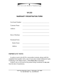
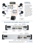
VK-655SE
WARRANTY REGISTRATION FORM
Unit Serial Number:
_______________________________________
Customer Name:
_______________________________________
Address:
_______________________________________
_______________________________________
Date of Purchase:
_______________________________________
Purchased From:
Dealer Name:
_______________________________________
Address:
_______________________________________
_______________________________________
IMPORTANT NOTE:
In order to receive the full five year product warranty, please
mail this completed form together with a copy of your sales
receipt to Balanced Audio Technology at the address below,
within thirty days of purchase.
Failure to do so will result in the product being warrantied for
one year from the date of manufacture.
1300 First State Blvd. Wilmington DE 19804 Tel: 302-999-8855 Fax: 302999-8818
VK-655SE Balanced Power
Amplifier
VK-600 M SE Balanced Monoblock
Owner's Manual
1300 First State Blvd. Wilmington DE 19804 Tel: 302-999-8855 Fax: 302999-8818
Introduction
Thank you for your purchase of the Balanced Audio Technology VK-655SE
balanced power amplifier. Please read this owner's manual to obtain the full
benefit of the VK-655SE in your system. It will provide you with the needed
safety information and operating procedures for this exceptional unit.
WARNINGS:
To prevent the possibility of serious injury, electrical shock or fire:
DO NOT operate with the cover removed.
DO NOT expose to rain or moisture.
DO NOT defeat the ground power-plug.
DO NOT replace fuses with anything other than the same type and rating as
supplied by the factory.
Package Contents
Included in the box should be the following:
Description
Quantity
VK-655SE Power Amplifier
Power Cords
Spare Fuses
Torx Wrench (T-10)
Spare Top Cover Screws
Owner’s Manual
Optional Accessories
1
2
3
5
1
1
(as ordered)
Save all the packaging material in a safe dry area for the unlikely event
that you need to return the VK-655SE to the factory for service.
Physical Placement
It is recommended that you provide for at least 6" of free space around the
unit for proper ventilation.
Mount the unit on a hard surface with proper ventilation underneath.
Do not stack other equipment on top of the VK-655SE power
amplifier.
IMPORTANT NOTES:
To assure reliable operation always turn the VK-655SE OFF while making or
changing input or speaker connections. No connections should be made
while the amplifier is ON.
If the VK-655SE was turned OFF for any reason, wait at least 30 seconds
before turning it back ON.
Power Connection
The VK-655SE is a true Dual Monoblock design with two separate power
cords. Due to the amplifier’ high power rating, it is important to assure the
good quality power line for each channel. If separate circuit outlets are used
for left and right channels, it is recommended that both circuits be
connected to the same phase of the power line. Otherwise, a high level of
hum can be present.
Input Connections
Best results will be obtained when connecting the VK-655SE to a balanced
preamplifier. However, the VK-655SE is designed to accept either balanced
or single-ended inputs.
Monoblock connection: On the VK-655SEM Balanced Monoblock either
the left or right channel input can be used – both will produce identical
results.
Balanced Components
Use balanced XLR interconnects to connect the VK-655SE to a balanced
preamplifier. Input connectors are clearly marked on the back panel.
Note: The VK-655SE input XLR connectors are wired as follows:
Pin 1:
Pin 2:
Pin 3:
common/shield
positive
negative
Single-Ended Components
Single-ended components have RCA connectors. The VK-655SE power
amplifier is designed to work with either single-ended or balanced
preamplifiers connected to its inputs. All that is required to connect a
single-ended preamplifier with RCA connectors to the
VK-655SE inputs is
the optional balanced to single-ended adapters. These adapters are available
from Balanced Audio Technology.
Input Adapters:
RCA Female to XLR Male
Speaker Connections
There are two sets of high quality binding posts on the back panel of the
VK-655SE (one for each channel). These can accommodate a wide
variety of speaker cable terminals. You can use a 1/2” wrench to tighten
these binding posts, however excessive force should be avoided to
eliminate the chance of breakage.
Monoblock connection: On VK-655SEM Balanced Monoblock either left
or right channel output can be used to connect speaker wires, or both, in
case of bi-wiring.
External 12V Trigger Input/Output
VK-655SE is equipped with the external 12V trigger connectors – Input
and Output. To control the VK-655SE the external device must supply
the standard 12V signal.
12V Trigger Output connector can be used to drive another device’s
input for daisy-chain operation of multiple units.
Operating the VK-655SE
Turning the VK-655SE On:
The power switch is located on the VK-655SE front panel. If VK-250 was
turned OFF even for a short period of time, you should wait at least 30
seconds before turning it back ON. This precaution will minimize the stress
on internal components.
When you turn the unit ON, the VK-655SE will automatically go through a
gentle power-on sequence. At the end of a 10 second delay the unit will
unmute and become operational.
Front Panel LED Indicators/ Remote Trigger Operation
When the VK-655SE is not connected to the external 12V Trigger line, its Blue ON indicator
will turn ON and OFF when the power switch is depressed.
When unit is connected to the external controller via the 12V Trigger line, the condition
of the LED indicators will depend on the state of that control line.
If the external controller is in OFF state (12V signal is not present), then the green Stanby
LED will light upon power switch activation. The unit will alternate between the
Standby and Off state every time the Power Switch is depressed.
When in its Standby mode, the unit will be controlled by the 12V Trigger line. When
that line issues the ON command (12V signal is present) the green Standby LED will go
out, and the blue ON LED will light.
Fuse Protection:
Each channel of the VK-655SE is protected by three fuses:
1. The main line fuses are located on the back panel. These fuses should
be checked if one of the front panel LED’s fail to light.
2. Two internal fuses are mounted on the amplifier circuit boards. These
fuses have two green LED’s associated with them. Both LED’s should be lit
when unit is ON and operating properly. Failure of either of these LED’s to
light indicates that the corresponding fuse is open.
CAUTION:
Make sure that the VK-655SE is turned OFF and disconnected from the
power line before checking or replacing fuses.
A blown fuse in the VK-655SE is potentially an indication of a serious
problem. If a replacement fuse fails as well, no further attempts at servicing
the unit should be undertaken. Please contact the factory for professional
service.
Fuse Ratings
The proper ratings for the main line fuse are as follows:
For 100-120 VAC Units:
10A 250V Slow Blow
For 200-240 VAC Units:
7A 250V Slow Blow
The internal printed circuit board mounted fuses are 15A Fast Acting
type.
Factory supplied fuses should be only replaced with the same
type and rating parts.
Servicing
The Balanced Audio Technology VK-655SE should not require service to
maintain its high performance. In case of malfunction, if replacing fuses fails
to eliminate the problem, please direct any further service inquiries to the
factory.
Terms and Conditions
Five Year Limited Warranty
1. Limited Warranty
Upon receipt of the attached warranty registration form, Balanced Audio Technology
warrants the purchased product to be free from manufacturing, materials, and workmanship
defects for five years from date of original purchase, excepting vacuum tubes, subject to
the following conditions. Failure to return the enclosed registration form within
30 days from original purchase will result in a warranty period of one year from
the date of manufacture.
2. Limited to Original Purchaser
This warranty is for the sole benefit of the original purchaser of the covered product, and
may not be transferred to a subsequent purchaser of the product.
3. Conditions and Limitations
This warranty is subject to certain conditions and limitations, as follows. This warranty is
void and inapplicable if the product has not been used in accordance with the instructions
found elsewhere in this manual, or if it has been misused or abused, damaged by accident or
neglect, or in transport once in possession of the purchaser. The warranty is also void if the
product has been repaired, modified, or tampered with by anyone other than Balanced Audio
Technology or its specifically authorized agents.
4. Remedy
If this product contains a materials, manufacturing, or workmanship defect that cannot be
repaired at the dealership where the product was purchased, it must be packed in original
packaging and returned to Balanced Audio Technology via insured freight, at the owners
expense. If replacement packaging materials are required, they will be supplied by the
factory at a nominal charge. Returned products must be accompanied by a written
description of the defect, and a return authorization number (available from
the factory via phone or fax). Upon receipt of defective product, Balanced Audio
Technology agrees to repair the product without charge for parts (except vacuum tubes if
the unit is more than one year old), or labor. The product will then be returned via prepaid,
insured freight, with carrier at the sole determination of Balanced Audio Technology. This
constitutes the purchasers sole remedy.
5. Design Changes
Balanced Audio Technology reserves the right to modify its products or change
specifications at any time without obligation or liability to previous purchasers.
6. Miscellaneous
Any implied warranties relating to the above product shall be limited to the duration of this
warranty. This warranty does not extend to any incidental or consequential costs or
damages to the purchaser. This warranty gives you specific legal rights. You may also have
other rights which vary from state to state.