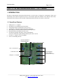
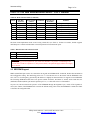
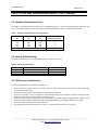
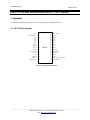
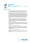
1
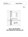
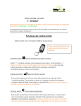
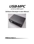
DatasheetDirect.com Your dedicated source for free downloadable datasheets. Over one million datasheets Optimized search function Rapid quote option Free unlimited downloads Visit www.datasheetdirect.com to get your free datasheets. This datasheet has been downloaded by http://www.datasheetdirect.com/ Philips Semiconductors Interconnectivity May 19, 1999 ISP1122 USB Hub Demonstration Board User’s Manual Revision 1.02 _____________________________________________________________________________________________ Philips Semiconductors - Asia Product Innovation Centre Visit http://www.flexiusb.com Interconnectivity Page 2 of 12 ISP1122 USB Hub Demonstration Board - User’s Manual This is a legal agreement between you (either an individual or an entity) and Philips Semiconductors. By accepting this product, you indicate your agreement to the disclaimer specified herein. DISCLAIMER PRODUCT IS DEEMED ACCEPTED BY RECIPIENT. THE PRODUCT IS PROVIDED “AS IS” WITHOUT WARRANTY OF ANY KIND. TO THE MAXIMUM EXTENT PERMITTED BY APPLICABLE LAW, PHILIPS SEMICONDUCTORS FURTHER DISCLAIMS ALL WARRANTIES, INCLUDING WITHOUT LIMITATION ANY IMPLIED WARRANTIES OF MERCHANT ABILITY, FITNESS FOR A PARTICULAR PURPOSE, AND NONINFRINGEMENT. THE ENTIRE RISK ARISING OUT OF THE USE OR PERFORMANCE OF THE PRODUCT AND DOCUMENTATION REMAINS WITH THE RECIPIENT. TO THE MAXIMUM EXTENT PERMITTED BY APPLICABLE LAW, IN NO EVENT SHALL PHILIPS SEMICONDUCTORS OR ITS SUPPLIERS BE LIABLE FOR ANY CONSEQUENTIAL, INCIDENTAL, DIRECT, INDIRECT, SPECIAL, PUNITIVE, OR OTHER DAMAGES WHATSOEVER (INCLUDING, WITHOUT LIMITATION, DAMAGES FOR LOSS OF BUSINESS PROFITS, BUSINESS INTERRUPTION, LOSS OF BUSINESS INFORMATION, OR OTHER PECUNIARY LOSS) ARISING OUT OF THIS AGREEMENT OR THE USE OF OR INABILITY TO USE THE PRODUCT, EVEN IF PHILIPS SEMICONDUCTORS HAS BEEN ADVISED OF THE POSSIBILITY OF SUCH DAMAGES. _____________________________________________________________________________________________ Philips Semiconductors - Asia Product Innovation Centre Visit http://www.flexiusb.com Interconnectivity Page 3 of 12 ISP1122 USB Hub Demonstration Board - User’s Manual Table of Contents PREFACE .....................................................................................................................................................................4 1 INTRODUCTION......................................................................................................................................................5 1.1 Demo Board Features ..........................................................................................................................................5 2 BOARD DESCRIPTION ...........................................................................................................................................6 2.1 Configuration Modes...........................................................................................................................................6 2.2 EEPROM Support ...............................................................................................................................................7 2.3 Number of Downstream Ports..............................................................................................................................9 2.4 Factory Default Setting........................................................................................................................................9 2.5 PCB Layout Considerations.................................................................................................................................9 3 Appendix .................................................................................................................................................................10 3.1 ISP1122 Pin Diagram........................................................................................................................................10 3.2 Bill of Material (BOM)......................................................................................................................................11 3.3 Component Placement.......................................................................................................................................12 _____________________________________________________________________________________________ Philips Semiconductors - Asia Product Innovation Centre Visit http://www.flexiusb.com Interconnectivity Page 4 of 12 ISP1122 USB Hub Demonstration Board - User’s Manual PREFACE The Philips Semiconductors Hub ISP1122 is a state of the art, 3rd generation, stand-alone USB hub controller IC that complies with the latest USB Spec Rev 1.1. The major considerations for this board are: 1. 2. 3. Interoperability Reduction in the overall system cost Ease of use We have relied on more than three years of our USB design and customer support experience to achieve these objectives. Today our USB products already provide an industry benchmark for the interoperability tests. Since interoperability problems result in the most expensive failures in the field, we have further tightened the design specifications to address many ambiguities. The IC has integrated many functions and offers features that reduce the major components of the total system cost. We have employed many design techniques to reduce the EMI emissions, increase the ESD resiliency and improve the manufacturing test criteria to insure a high quality product. Our ultimate aim is to provide you with peace of mind when using our products in the total system solution. We welcome your comments and suggestions to help us improve. For more information about the ISP1122 and the latest updates to the design support document, please visit the web site http://www.flexiusb.com/ With Best Regards, Team Members of the Asia Product Innovation Center _____________________________________________________________________________________________ Philips Semiconductors - Asia Product Innovation Centre Visit http://www.flexiusb.com Interconnectivity Page 5 of 12 ISP1122 USB Hub Demonstration Board - User’s Manual 1 INTRODUCTION The ISP1122 demonstration board (henceforth referred to as demo board) is designed for evaluating the features and functionality of the ISP1122 integrated circuit (IC). This manual explains the schematic of the ISP1122 demo board, demonstrates the PCB layout, shows the Bill of Material (BOM) and describes the switches on the board. 1.1 Demo Board Features • • • • • • • • • USB Spec Rev 1.1 compliant Selectable bus or self/hybrid-powered operation Configurable number of downstream ports from 2 to 5 Customizable Vendor ID and Product ID through EEPROM Individual power switching and individual overcurrent protection Hub health indicator through GoodLinkTM LED Verified interoperability with many systems and peripherals (Check the continuously updated Interoperability report on the web site) FCC Part 15 , Subpart J, Class B compliant 8 kV in-circuit ESD protection Optional VID/PID in external EEPROM 6 MHz crystal for lower EMI Bus- or self-powered Individual pMOS switches (built-in overcurrent detection) GoodLink™ LED USB Spec 1.1 compliant Configurable from 2 to 5 ports _____________________________________________________________________________________________ Philips Semiconductors - Asia Product Innovation Centre Visit http://www.flexiusb.com Interconnectivity Page 6 of 12 ISP1122 USB Hub Demonstration Board - User’s Manual 2 BOARD DESCRIPTION 2.1 Configuration Modes The INDV, OPTION and SP/BP_N pins determine the hub configuration modes. Users can set these signals to logic high or low. The INDV and OPTION pins can also be used for connections to external EEPROM. This allows for customized Vendor ID and Product ID among other configuration modes. The contents of the EEPROM will be described later. The three configuration pins are described in Table 1. Table 1 Mode Configuration Pins Name Value INDV 0 1* OPTION 0 1* SP/BP_N 0 1 Description Other Usage Gang power switching and global overcurrent protection mode SCL Individual power switching and individual overcurrent protection mode Both power switch and overcurrent protection functions are SDA active Only one function is active: in self-powered mode, the power switch control is inactive; in bus-powered operation, the overcurrent protection is inactive Bus-powered mode Self-powered or hybrid powered mode Local Power Lost Indication 1* signifies a pull-up high. Note: The ISP1122 also supports hybrid self-powered mode. In this mode, the hub controller draws power from upstream Vbus and local power is used for downstream ports. Hybrid powered mode is advantageous to differentiate between a disconnected and an unpowered device. This makes it possible to keep communicating between the host and the device/hub even if local power is lost. Each composite setting of the three pins determines one configuration mode of the hub. Therefore, ISP1122 can be configured into eight modes. Table 2 shows these configuration modes. For a detailed description of these power management modes, refer to the “ISP1122 Power Management Design Guide” document. Table 2a Mode Selection Table Mode 0 1 2 3 4 5 6 7 INDV 0 0 0 0 1 1 1 1 OPTION 0 0 1 1 0 0 1 1 SP/BP_N 0 1 0 1 0 1 0 1 PSW1,2,3,4_N GL1,2,3,4_N GL1,2,3,4_N GL1,2,3,4_N GL1,2,3,4_N PSW1,2,3,4_N PSW1,2,3,4_N PSW1,2,3,4_N GL1,2,3,4_N PSW5_N GPSW_N GPSW_N GPSW_N GL5_N Inactive PSW5_N Inactive GL5_N OC1,2,3,4_N Inactive Inactive Inactive Inactive OC1,2,3,4_N OC1,2,3,4_N Inactive OC1,2,3,4_N OC5_N GOC_N GOC_N Inactive GOC_N Inactive OC5_N Inactive OC5_N Inactive OCX_N pins must be tied to Vcc. _____________________________________________________________________________________________ Philips Semiconductors - Asia Product Innovation Centre Visit http://www.flexiusb.com Interconnectivity Page 7 of 12 ISP1122 USB Hub Demonstration Board - User’s Manual Table 2b Mode Selection Table (Continued) Mode 0 1 2 3 4 5 6 7 Self-/BusPowered Bus-powered Self-powered Bus-powered Self-powered Bus-powered Self-powered Bus-powered Self-powered Power Switch control Ganged Ganged Ganged Inactive Individual* Individual Individual* Inactive GoodLink Yes* Yes* Yes* Yes No No No Yes Overcurrent Protection Global Global Inactive Global Individual* Individual Inactive Individual Remarks Ganged and bus powered Ganged and self powered No overcurrent No power switch control Individual and bus powered Individual and self powered No overcurrent No Power switch control * Without Port 5 The demo board implements modes 4 and 5 using switch SW1 (see Table 3). In these two modes, the hub supports individual power control and individual overcurrent protection for downstream ports. Table 3 Bus/Self-Powered Selection Switch SW1 1-3 1-2 Selection Bus powered Self/Hybrid powered WARNING: When supplying power through the DC jack, make sure that SW1 is at position 1-2 indicating a selfpowered mode. If SW1 is at position 1-3 (bus-powered mode), the upstream supply and the local supply will be shorted! 2.2 EEPROM Support INDV and OPTION pins can also be connected to an external serial EEPROM for Vendor ID, Product ID customization and configuration setting. The interfacing protocol is I2C. The ISP1122 acts as the master and the EEPROM as the slave. The I2C clock frequency generated by the ISP1122 is slightly less than 100 kbits/s to support low end EEPROM. The following EEPROM models have been proven suitable: PCA8581, PCF8582C-2, 24C00, 24C01. Both the SCL (OPTION) and SDA (INDV) pins must be pulled up to Vcc; a 3.3 kilo-ohm value is recommended. On power on, ISP1122 detects the presence of the EEPROM through the Signature byte (=AAh). If the signature is correct, the content of the EEPROM will overwrite the default setting. Table 4 lists the EEPROM’s contents and Table 5 describes the configuration bits. _____________________________________________________________________________________________ Philips Semiconductors - Asia Product Innovation Centre Visit http://www.flexiusb.com Interconnectivity Page 8 of 12 ISP1122 USB Hub Demonstration Board - User’s Manual Table 4 EEPROM Content Address 0 1 2 3 4 5 C7 Content idVendor lower byte (default = CCh) idVendor higher byte (default = 04h) idProduct lower byte (default = 22h) idProduct higher byte (default = 11h) C6 C5 C4 C3 C2 C1 Signature = AAh C0 Table 5 Configuration Bits Bit C0 C1 C2 Name OPTION INDV RESERVED Value C3 PwrOn2PwrGood C4 String Descriptor Enable 0* 1 0* 1 C5 Internal Analog Overcurrent Detection Enable C7:6 MaxPower 0* 0 1* 00* 01 1X Meaning Refer to mode selection table Refer to mode selection table Should always be programmed to ‘0’ Modifies the Hub Descriptor Field PwrOn2PwrGood 100 ms (32h) 500 ms (FAh) Disable String Descriptor Enable String Descriptor (String is “Philips Semiconductors” and “ISP1122”) Disable internal analog overcurrent detection circuit. When disabled, the overcurrent pins OCX_N convert to digital (TTL) level. Enable internal analog overcurrent detection circuit Modifies the Configuration Descriptor Field MaxPower 100 mA (32h) 500 mA (FAh) 0 mA (00h) Note: * denotes the internal default value when the EEPROM is not present. Although the C0 (OPTION) and C1 (INDV) bits can be programmed to any value, the demo board hardware only supports Modes 4 and 5. That means these two bits must be programmed with C0 (OPTION) = 0 C1 (INDV) = 1 for this demo board to work. The EEPROM can be disabled through switch SW2 as shown in Table 6. When the EEPROM is not present, switch SW2 has to be set to “EEPROM disabled” state to correctly configure the board in the right mode of operation (Modes 4 or 5). Table 6 EEPROM Enable/Disable Switch SW2 EEPROM 1-3 EEPROM enabled 1-2 EEPROM disabled _____________________________________________________________________________________________ Philips Semiconductors - Asia Product Innovation Centre Visit http://www.flexiusb.com Interconnectivity Page 9 of 12 ISP1122 USB Hub Demonstration Board - User’s Manual 2.3 Number of Downstream Ports The number of downstream ports for ISP1122 is configurable from 2 to 5. For bus-powered mode, the USB spec only allows for 4 downstream ports. Table 7 lists the port number configuration, which is set through switch SW3. Table 7 Number of Downstream Ports Setting (SW3) 1-12 2-11 OFF ON ON ON 3-10 4-9 OFF OFF ON ON Other combinations 5-8 6-7 OFF OFF OFF ON Number of Downstream Ports 5 4 3 2 Illegal Note: Bus-powered mode can only have 4 downstream ports according to the USB spec. 2.4 Factory Default Setting The factory default setting of the configuration switches are shown in Table 8. Table 8 Factory Default Setting Switch SW1 SW2 SW3 Selection Self/Bus-powered EEPROM Number of Downstream Ports Default Bus-powered No EEPROM (disabled) 4 2.5 PCB Layout Considerations The following PCB layout considerations are employed: 1. 2. 3. 4. 5. 6. Route signal traces on the top layer as much as possible. The bottom layer is reserved for ground routing. This should minimize EMI issues. Power traces must be thick to meet USB spec voltage drop requirement. Put 150 µF capacitors as close as possible to the downstream ports. These capacitors, together with ferrite beads, minimize voltage droop upon downstream ports hot insertion. Route each pair of the D+ and D- lines close and parallel to each other and their length should be equalized. This will ensure good symmetrical differential signal swing that enhances interoperability and also lower EMI. Crystal oscillator should be placed close to ISP1122. Decoupling capacitors for the ISP1122 Vcc and V3.3 signals should be placed close to the pins. _____________________________________________________________________________________________ Philips Semiconductors - Asia Product Innovation Centre Visit http://www.flexiusb.com Interconnectivity Page 10 of 12 ISP1122 USB Hub Demonstration Board - User’s Manual 3 Appendix For schematic diagram and PCB layout, refer to their respective .SCH and .PCB files. 3.1 ISP1122 Pin Diagram V3.3 1 32 PSW1_N/GL1_N PSW2_N/GL2_N 2 31 DP2 GND 3 30 DM2 DM3 4 29 DP0 DP3 5 28 DM0 VCC 6 27 DP1 OC1_N 7 26 DM1 OC2_N 8 25 DP5 OC3_N 9 24 DM5 OC4_N 10 23 INDV/SCL OC5_N/GOC_N 11 22 OPTION/SDA DM4 12 21 RESET_N DP4 13 20 XTAL2 SP/BP_N 14 19 XTAL1 HUBGL_N 15 18 PSW5_N/GL5_N/GPSW_N PSW3_N/GL3_N 16 17 PSW4_N/GL4_N ISP1122 Figure 1 Pin Diagram of ISP1122 _____________________________________________________________________________________________ Philips Semiconductors - Asia Product Innovation Centre Visit http://www.flexiusb.com Interconnectivity Page 11 of 12 ISP1122 USB Hub Demonstration Board - User’s Manual 3.2 Bill of Material (BOM) Part # Part Type Designator 1 0.01µF ceramic capacitors C26,C27,C28,C29,C40,C41 2 0.1µF ceramic capacitor C3, C6, C7,C8,C9,C10,C11 3 1µF TANT capacitors C4, C13,C16 4 4.7µF TANT capacitor C25 5 150µF Electrolytic capacitor C20, C21, C22, C23, C24 6 22pF ceramic capacitor C1, C2 7 47pF ceramic capacitor 8 100 kilo-ohm 0805 C30, C31, C32, C33, C34, C35, C36, C37, C38, C39 R43, R44, R45, R46, R47 9 1.5 kilo-ohm 5% 0805 R21 10 10 kilo-ohm 5% 0805 R14 11 15 kilo-ohm 5% 0805 12 18 ohm 1% 0805 13 3.3 kilo-ohm 0805 R22, R23, R24, R25, R26, R27, R28, R29,R30 R1, R2, R3, R4, R5, R6, R7, R8, R9, R10, R11, R12 R32, R33 14 330 ohm 0805 R15 15 47 kilo-ohm 0805 R34, R35, R36, R37, R38 16 Ferrite beads – Murata BLM31P221SG 17 Common mode choke filter- Murata PLP3216S551SL2 FB1, FB3, FB5, FB7, FB9, FB11, FB13, FB15, FB17, FB19, FB21, FB23 FB2, FB6, FB10, FB14, FB18 18 6 MHz Crystal oscillator X1 19 5V/2.5A DC jack P1 20 USB “A” Receptacle (Downstream port connectors) J1, J2, J3, J4, J5 21 USB “B” Receptacle (Upstream port connector) J0 22 24 ISP1122. Philips Semiconductors USB Hub controller (SO32 U1 package) 2 PCA8581C/PCF8582C-2/24C00/24C01. EEPROM with I C U2 interface PHP109. PMOS power transistor Q1, Q2, Q3, Q4, Q5 25 LED LED1 26 Switch DIP-6 SW3 27 Switch SPDT SW2 28 Switch DPDT SW1 29 TEST POINT TP1 23 Qty 6 7 3 1 5 2 10 5 1 1 10 12 2 1 5 12 5 1 1 5 1 1 1 5 1 1 1 1 1 _____________________________________________________________________________________________ Philips Semiconductors - Asia Product Innovation Centre Visit http://www.flexiusb.com Interconnectivity Page 12 of 12 ISP1122 USB Hub Demonstration Board - User’s Manual 3.3 Component Placement Downstream Downstream Downstream Port 5 Port 4 Port 3 Downstream Port 2 Downstream Port 1 Figure 2 Component Placement of the ISP1122 Demo Board _____________________________________________________________________________________________ Philips Semiconductors - Asia Product Innovation Centre Visit http://www.flexiusb.com