1
FA-PC
VPC Series
Space-Saving Model
VPC-1500
User’s Manual
CONTEC CO., LTD.
Table of contents
Table of contents ........................................................................................................................... i
CHAPTER1 INTRODUCTION
1
◆Basic performance ............................................................................................................... 1
◆Commodity model ................................................................................................................... 2
◆Supported OS ......................................................................................................................... 2
Customer support ............................................................................................................................ 3
◆Web Site ................................................................................................................................. 3
◆Limited One-Year Warranty ............................................................................................... 3
◆How to Obtain Service ....................................................................................................... 4
◆Liability ............................................................................................................................... 4
Safety precaution .......................................................................................................................... 4
◆Safety infomation ............................................................................................................... 4
◆Handling precautions ......................................................................................................... 5
CHAPTER2 ABOUT THE PRODUCT
7
Specification .................................................................................................................................. 7
Physical dimensions ...................................................................................................................... 9
Keyboard specification .............................................................................................................. 12
Mouse specification .................................................................................................................... 12
CHAPTER3 HARDWARE SETUP
13
Before Using the VPC-1500 for the First Time .................................................................. 13
Hardware setup .............................................................................................................................. 14
◆Removing the top cover and drive bay ....................................................................... 14
◆Locations and settings of internal connectors and jumpers ............................. 17
◆Jumper setting ................................................................................................................... 19
■Attach the hard disk ....................................................................................................... 21
■Replacing the front fan unit and fan filter ......................................................... 25
■Replacing the CMOS battery ........................................................................................... 29
■Option: Attach the vertical stand ............................................................................. 32
■Option: Attach the horizontal installation bracket ........................................... 33
■Installation requirements ............................................................................................. 34
CHAPTER4 BIOS SETUP
37
◆Starting the setup screen ............................................................................................. 37
◆Key operation ..................................................................................................................... 38
◆Main window ......................................................................................................................... 39
◆Setting of the date and time ....................................................................................... 39
◆Setting of the start password ..................................................................................... 40
User’s Manual
i
◆Release of setted the password ................................................................................... 40
◆Changing to the device boot order ............................................................................. 41
◆ Selecting to the IDE device.................................................................................... 42
◆ Setting for the power on (AT power operation) by the AC power-supply turning
on 43
◆Factory default setting ................................................................................................. 44
CHAPTER5 EACH COMPONENT FUNCTION
57
◆Component name ................................................................................................................... 57
◆Keyboard interface ........................................................................................................... 59
◆Mouse interface ................................................................................................................. 59
◆Serial port interface ..................................................................................................... 60
◆CRT interface ..................................................................................................................... 61
◆Printer port interface ................................................................................................... 62
◆Reset switch ....................................................................................................................... 63
◆Power switch ....................................................................................................................... 63
◆USB port ............................................................................................................................... 63
◆Ethernet ............................................................................................................................... 64
◆Digital I/O interface ..................................................................................................... 65
◆Audio interface ................................................................................................................. 67
CHAPTER6 SOFTWARE UTIRITY
69
◆Driver DVD ........................................................................................................................... 69
◆Various drivers ................................................................................................................. 69
◆IO-Lib ................................................................................................................................... 70
◆RAS tool ............................................................................................................................... 75
◆Hardware RAID monitoring tool ..................................................................................... 79
◆Watch-Dog Timer (WDT) Setting ..................................................................................... 95
◆Hardware monitor ............................................................................................................... 96
◆General purpose input ..................................................................................................... 99
◆General purpose output ................................................................................................. 100
CHAPTER7 SOFTWARE RAID SETUP
101
◆Starting the setup screen ........................................................................................... 101
◆Main window ....................................................................................................................... 102
◆Create RAID drive (Mirroring) ................................................................................... 103
◆Delete RAID drive (Mirroring) ................................................................................... 105
◆Software RAID monitoring tool(Matrix storage console) ................................... 106
◆Matrix storage console Install ................................................................................. 106
◆Starting the matrix storage console ....................................................................... 106
◆Exiting the matrix storage console ......................................................................... 107
◆Making of mirroring synchronize ............................................................................... 108
◆Create RAID drive (Mirroring) ................................................................................... 109
◆Delete RAID drive (Mirroring) ................................................................................... 110
◆For the error ................................................................................................................... 111
ii
User’s Manual
◆Confirming the error log ............................................................................................. 112
◆RAID setup when replacing the HDD ........................................................................... 113
◆RAID setup when replacing the HDD ........................................................................... 113
CHAPTER8 HARDWARE RAID SETUP
115
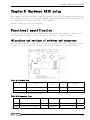
Functional specification ........................................................................................................ 115
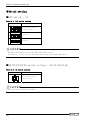
◆Locations and settings of switches and connectors ........................................... 115
◆Switch setting ................................................................................................................. 116
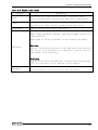
◆Internal LED status ....................................................................................................... 117
Hardware RAID setup .................................................................................................................. 118
◆Operation flow ................................................................................................................. 118
◆For the error ................................................................................................................... 120
◆RAID setup when replacing the HDD ........................................................................... 121
◆Hot-swap ............................................................................................................................. 122
OS recovery setting .................................................................................................................. 123
FAQ・Troubleshooting ................................................................................................................ 124
◆FAQ ....................................................................................................................................... 124
◆Troubleshooting ............................................................................................................... 125
CHAPTER9 LIST OF OPTIONS
129
User’s Manual
iii
iv
User’s Manual
Chapter1 Introduction
The VPC-1500 series is a BTO industrial PC that is equipped with either an Intel® Core2Duo
E8400 (3.0GHz), or Celeron440 (2.0GHz). The Intel® Q45 chipset with DDR3 memory (2GB to
4GB) provides a system with extreme computing and graphics performance. These products
feature a variety of interfaces, including 6 USB ports (Front: 2, Rear: 4), 2 1000BASE-T
ports, 4 RS-232c port and 1 parallel port. These units are ideal for a wide range of embedded
applications, such as control devices and information terminals based on general-purpose
PC OSes. This series provides carefree use under harsh working conditions such as FA,
achieving superb environmental resistance and a long-term stable supply due to careful
selection of parts such as embedded CPUs and chipsets.
The chassis of the VPC-1500 series is available in the following two colors.
Base Model
VPC-1500 Black
VPC-1500 Ivory
◆Basic performance
・ Intel(R)Core2Duo is installed (※Core2Duo Model)
Embedding a high-performance CPU, the VPC-1500 series has achieved lower prices.
・ Intel(R)Q45 Chipset is adopted
Employing an embedded-style chipset, the VPC-1500 series has achieved a long-term
stable supply.
・ It Corresponds to mirroring(RAID1)
It is possible to have mirroring configurations, enabling redundant systems with the
following RAIDs.
[Software RAID]
It is possible to have software mirroring configuration by employing ICH10DO at the
southbridge. However, it can not hot-swap.
[Hardware RAID]
Because option : Mirror card is choiced, it is possible to have Hardware mirroring
configurations. This can hot-swap.
・ Suitable chassis for embedded applications
Taking advantage of our rich experience, the VPC-1500 series is designed with
optimization for heat dissipation, operating vibration dampening and consideration
for scalability.
・ Supports high-speed high-capacity memory
The VPC-1500 series supports DDR3 SDRAM DIMM modules (2GB to 4GB in total) designed
for high-speed transfer speed, flexibly addressing memory-consuming applications such
as image processing.
User’s Manual
1
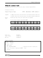
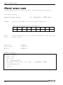
◆Commodity model
VPC-1500 Model rule
・Model name
VPC-1500
・Type name
W
S C1 1
1
0
0
1
0
0
0
0
① ② ③ ④ ⑤ ⑥ ⑦ ⑧ ⑨ ⑩ ⑪ ⑫
0
0
⑬
0
⑭
① Chassis
W : Ivory
B : Black
⑧ Optics system drive
1 : DVD Super Multi Drive
2 : DVD Super Multi Drive (With writing software)
② Power
S : Made in China
H : Made in Japan
⑨ Operating system
0 : None
2 : Windows XP Professional Japanese
3 : Windows 7 Professional Japanese
A : Windows 2000 Professional Multilanguage(JPN/ENG/CHS
B : Windows XP Pfofessional Multilanguage(JPN/ENG/CHS)
C : Windows XP Embedded Multilanguage(JPN/ENG/CHS)
③ CPU
C1 : Celeron 440(2.0GHz FSB 800MHz)
D1 : Core2Duo E8400 (3.0GHz FSB 1333MHz)
④ Memory
7 :
8 :
9 :
A :
PC-10600
PC-10600
PC-10600
PC-10600
DDR3
DDR3
DDR3
DDR3
1GB(1GB×1)
2GB(1GB×2)
2GB(2GB×1)
4GB(2GB×2)
⑤ Hard
0
2
C
disk (SATA1)
: None
: 250GB 3.5inch HDD(SATA)
: 2TB 3.5inch HDD(SATA)
⑥ Hard
0
2
C
disk (SATA2)
: None
: 250GB 3.5inch HDD(SATA)
: 2TB 3.5inch HDD(SATA)
⑦ Mirroring
0 : None
R : Software Mirroring
H : Hardware Mirroring
⑩ Keyboard
0 : None
1 : Japanese 109 Keyboard (PS/2)
A : English 104 Keyboard (PS/2)
⑪ Mouse
0 :
1 :
None
Mouse (PS/2)
⑫ Stand
0 :
W :
T :
None
Horizontal installation bracket
Vertical stand
⑬ Reserve
⑭ Onsite
0 :
2 :
3 :
Maintenance Service
None
Onsite maintenance service of two years
Onsite maintenance service of three years
◆Supported OS
・ Windows XP Professional
・ Windows XP Embedded
・ Windows 7 Professional
2
User’s Manual
Customer support
CONTEC provides the following support services for you to use CONTEC products more
efficiently and
comfortably.
◆Web Site
Japanese
English
Chinese
http://www.contec.co.jp/
http://www.contec.com/
http://www.contec.com.cn/
■Latest product information
CONTEC provides up-to-date information on products.
CONTEC also provides product manuals and various technical documents in the PDF.
■Note! For product information
Contact your retailer if you have any technical question about a CONTEC product or need
its price,
delivery time, or estimate information.
◆Limited One-Year Warranty
CONTEC products are warranted by CONTEC CO., LTD. to be free from defects in material and
workmanship for up to one year from the date of purchase by the original purchaser.
Repair will be free of charge only when this device is returned freight prepaid with a
copy of the original
invoice and a Return Merchandise Authorization to the distributor or the CONTEC group
office, from
which it was purchased.
This warranty is not applicable for scratches or normal wear, but only for the electronic
circuitry and
original products. The warranty is not applicable if the device has been tampered with
or damaged
through abuse, mistreatment, neglect, or unreasonable use, or if the original invoice is
not included, in
which case repairs will be considered beyond the warranty policy.
User’s Manual
3
◆How to Obtain Service
For replacement or repair, return the device freight prepaid, with a copy of the original
invoice. Please
obtain a Return Merchandise Authorization number (RMA) from the CONTEC group office where
you
purchased before returning any product.
* No product will be accepted by CONTEC group without the RMA number.
◆Liability
The obligation of the warrantor is solely to repair or replace the product. In no event
will the warrantor
be liable for any incidental or consequential damages due to such defect or consequences
that arise from
inexperienced usage, misuse, or malfunction of this device.
Safety precaution
Understand the following definitions and precautions to use the product safely.
◆Safety infomation
This document provides safety information using the following symbols to prevent accidents
resulting in
injury or death and the destruction of equipment and resources. Understand the meanings
of these labels
to operate the equipment safely.
DANGER indicates an imminently hazardous situation which, if not
avoided, will
result in death or serious injury.
WARNING indicates a potentially hazardous situation which, if not
avoided, could result in death or serious injury.
CAUTION indicates a potentially hazardous situation which, if not
avoided, may
result in minor or moderate injury or in property damage.
4
User’s Manual
◆Handling precautions
CAUTION indicates a potentially hazardous situation which,
if not avoided, may result in minor or moderate injury or in
property damage.
・ Do not use or store the product in a location exposed to extremely high or low
temperature or susceptible to rapid temperature changes.
Example
・Exposure to direct sun
・In the vicinity of a heat source
・ Do not use the product in extremely humid or dusty locations. It is extremely dangerous
to use the product with its interior penetrated by water or any other fluid or
conductive dust. If the product must be used in such an environment, install it on
a dust-proof control panel, for example.
・ Avoid using or storing the device in locations subject to shock or vibration.
・ Do not use the product in the vicinity of devices that generate strong magnetic force
or noise.
Such devices will cause this device to malfunction.
・ Do not use or store the product in the presence of chemicals.
・ To clean, wipe it gently with a soft cloth dampened with either water or mild
detergent.
Do not use chemicals or a volatile solvent, such as benzene or thinner, to prevent
pealing, discoloration of the paint, or deterioration of resin.
・ As continuous operation of the equipment may shorten the life of the hard disk drive,
use it in stand-by mode.
・ Be sure to unplug the power cable from a wall outlet before plugging or unplugging
a extension board or any connector.
・ CONTEC reserves the right to refuse to service a product modified by the user.
・ In the event of failure or abnormality (foul smells or excessive heat generation),
unplug the power cord immediately and contact your retailer.
・ Use an AC cable suitable for your supply voltage and outlet/plug. (The supplied cable
is for 125V AC.
・ The hard disk must be replaced when the power of the main unit is off. It is not
hot-swappable. Removing the hard disk during operation may damage the system.
(However, hardware raid is excluded.)
・ Component Life:
(1)Power・・・・・During continuous operation at 40℃, the assumed life is about four
years (vertical installation). However, it may be shortened due to
operating temperature (high temperatures).
(2)Battery・・・The internal calendar clock and CMOS RAM are backed by a Lithium primary
battery. The backup time at a temperature of 25°C with the power
disconnected is 10 years or more.
* Replacement of expendables is handled as a repair (there will be a charge).
・ To connect with peripherals, use a grounded, shielded cable.
・ Do not use a UPS (uninterruptible power supply) with square-wave output, as connecting
it may damage the system.
・ Risk of explosion if battery is replaced by an incorrect type. Dispose of used
batteries according to the instructions.
・ Abandon a used battery appropriately according to the instruction of the municipality.
User’s Manual
5
FCC PART 15 Class A Notice
NOTE
This equipment has been tested and found to comply with the limits for a Class A digital device,
pursuant to part 15 of the FCC Rules. These limits are designed to provide reasonable protection
against harmful interference when the equipment is operated in commercial environment.
This equipment generates, uses, and can radiate radio frequency energy and, if not installed and
used in accordance with the instruction manual, may cause harmful interference to radio
communications. Operation of this equipment in a residential area is likely to cause harmful
interference at his own expense.
WARNING TO USER
Change or modifications not expressly approved the manufacturer can void the user's authority to
operate this equipment.
Copyright
・
No part of this document may be copied or reproduced in any form by any means without
prior written consent of CONTEC CO., LTD.
・ CONTEC CO., LTD. makes no commitment to update or keep current the information contained
in this document.
The information in this document is subject to change without notice.
・ All relevant issues have been considered in the preparation of this document. Should
you notice an omission or any questionable item in this document, please feel free
to notify CONTEC CO., LTD.
・ Regardless of the foregoing statement, CONTEC assumes no responsibility for any errors
that may
appear in this document or for results obtained by the user as a result of using this
product.
・ Intel, Pentium are registered trademarks of Intel Corporation.
MS, Microsoft and Windows are trademarks of Microsoft Corporation.
Other brand and product names are trademarks of their respective holder. ™ and ® mark
are omitted in this document.
The latest version manual downloads from CONTEC web site.
6
User’s Manual
Chapter2 About the product
Chapter2 About the product
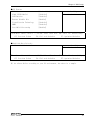
Specification
Functional specification
Main board Specification
CPU※1
Chipset
BIOS ROM
Memory※1
Display functional
Hard disk drive※1
Optical drive
VGA
USB port
PS/2 port
Audio
Sirial
Parallel
LAN port
Degital I/O
RAS function
Extended slot (Free)
OS※1
・Core2Duo E8400 ---------------- 3.0GHz/FSB1333MHz
・Celeron440 -------------------- 2.0GHz/FSB800MHz
Intel(R) Q45 / ICH10DO
Award BIOS
2GB(1024MB×1),4GB(2048MB×2)DDR3 SDRAM PC3-10600
Intel Q45 Integrated GMA 4500 Graphics
・SATAⅡ 3.5”HDD 250GB/2TB (Software/Hardware)RAID1
・SATAⅡ 3.5”HDD 250GB/2TB ×1 or ×2
DVD super multi drive
Max. reading speed DVD-ROM x8, CD-ROM x24
Max. writing speed DVD+/-R x8, DVD+/-R-DL x8, DVD-RW x6,
DVD+R x8, DVD-RAM x5,
CD-R x24, CD-RW x24
Analog RGB(D-SUB 15Pin)
Front 2 port Rear 4 port
2 port (Keyboard/Mouse)
HDAC/ALC883 CODEC (7.1+2CH audio codec)
RS-232C D-SUB 9pin×4
D-SUB 25pin×1
10BASE-T/100BASE-TX/1000BASE-T RJ45×2
Rear:output x2、Input x2
Front:LED output x2 ※4
(Software API support、User application)
WDT:1sec~255sec(Resetting operation by end)
Remote reset/Remote power on External input signal
Software RAS function
(Fan rotation、temperature、Voltage data reading)
PCIx3 (3) ※5 ※6
Installation max. dimension:176.41mm(L)×106.68mm(H)
・WindowsXP Professional
・Windows7 Professional
・WindowsXP Embedded
Mount Bracket
Stand※2
Physical dimensions(mm)/ 115(W) x 415(D) x 310(H)(No protrusions)/About 8Kg※3
Weight
Power
270W ATX Power(90-264VAC(47-63Hz) Automatic input switch)
※1 Implement and install the options you selected.
※2 Install the options you selected.
※3 Only the weight of the main unit. It weighs about 8.4kg in RAID configuration.
※4 Front LED ×2 are used by option of hardware raid utility.
※5 The extension board that connects the cable for the height of the connector toexceed
10mm cannot use upper row / the lower extended slot.
※6 You can not be used ECH(PCI)BE-F13A and ECH(PCI)BE-H13A of PCI bus extension chassis
made by CONTEC.
User’s Manual
7
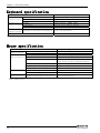
Chapter2 About the product
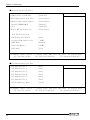
Ambient specification
Operating temperature/
humidity
Storage temperature/humidity
Floating dust particles/
Corrosive gases
Line-noise
resistance
Static
electricity
resistance
Line noise
Vibration
resistance
Sweep
resistance
Impact resistance
Standard
5~40℃/20~80%RH(No condensation)
-20℃~60℃/5~80%RH(No condensation)
Not to be excessive/None
Contact discharge
/±4KV(EN61000-4-2Level2,IEC1000-4-2 Level2)
Atmospheric discharge
/±8KV(EN61000-4-2Level3,IEC1000-4-2 Level3)
AC line/2KV,Signal line/1KV
(EN61000-4-4Level3,IEC1000-4-4Level3)
10~57Hz/semi-amplitude 0.015m 57~150Hz/0.2G
40 min each X,Y, and Z directions (JIS C0040
compliant、IEC68-2-6 compliant)
10G, half-sine shock for 11 ms in X,Y, and Z
directions
(JIS C0041 compliant, IEC68-2-27 compliant)
RoHS
EMC (EN55022、EN61000-6-2) and LVD (EN60950-1)
(注) Do not use under environmental conditions beyond normal specifications. The system may malfunction.
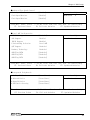
Option Mirror card specification
Item
Number of connected drivers
2
RAID level
1
Storage capacity
Max. 2TB
Cache memory size
1MB
Host interface
Drive interface
Range of power-supply voltage
8
Specification
S-ATA interface
Max. data transfer rate:3Gbps
S-ATA interface
Max. data transfer rate:3Gbps
4.75VDC~5.25VDC
Current consumption
1.0A
Physical dimensions (L×W)
96mm × 98.2mm
Weight
42g
User’s Manual
Chapter2 About the product
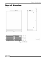
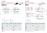
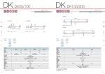
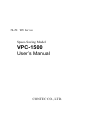
Physical dimensions
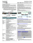
VPC-1500
Figure 2.1 VPC-1500
User’s Manual
9
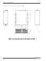
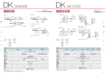
Chapter2 About the product
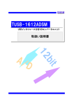
At installation the wall mount stand of VPC-1500
Figure 2.2 At installation the wall mount stand of VPC-1500
10
User’s Manual
Chapter2 About the product
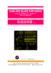
At installation the vertical stand of VPC-1500
Figure 2.3 At installation the vertical stand of VPC-1500
User’s Manual
11
Chapter2 About the product
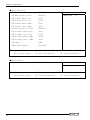
Keyboard specification
Mechanical
spesification
Electrical
specification
Item
Key array
Key switch
Length of cable(mm)
Power
Interface
Connector
Environment
Dustproof/Waterproof/Dripproof
specification
Color
※VPC-1500 option
Specification
Japanese 109 key, English 104 key
Membrane switch
1500±100
DC5V±0.25V, 100mA (MAX)
Clock cycle serial(PS/2)
PS/2 (mini-DIN6pin male)
Non-correspondence
Ivory
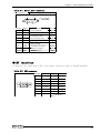
Mouse specification
Electrical
specification
Physical
specification
Tracking
Item
Operation voltage
Max. current consumption
Interface (Connector)
Body color
Button
Number of wheels
Length of cable
Physical dimensions (H x D x W)
Resolution
Max. tracking speed
Environment
Dustproof/Waterproof/Dripproof
specification
※VPC-1500 option
12
Specification
DC +5V (±0.5V)
25mA
PS/2 (mini-DIN6pin male)
White
3 Piece
(One piece on the insideisa wheel.)
1 Piece
1850mm (±50mm)
39.5mm x 117mm x 62.1mm
400dpi
250mm/sec
Non-correspondence
User’s Manual
Chapter3 Hardware setup
Chapter3 Hardware setup
Before Using the VPC-1500 for the First Time
Follow the next steps to set up the VPC-1500.
STEP1
Install Hard disk, Memory (DIMM) packaging, CD-ROM, DVD Multi drive packaging,
and set Jumper switches.
By referring to the information in this chapter, set the VPC-1500.
STEP2
Connect cables.
Connect the cable of necessary external devices, such as Printer and CRT,
to this product using appropriate cables.
STEP3
Tuen on the Power
After venifying that you have correctly steps 1 and 2, turn on the power.
If you find any abnormality after turning on the power, turn it off and check
to see if the setup has been performed properly.
STEP4
BIOS Setup
By referring to Chapter 4, setup BIOS. This setup requires a keyboard and
a display.
※ Before using the VPC-1500, be sure to execute “Load Optimized Defaults”
to initialize the BIOS settings to their default values.
(See Chapter 4, “Exit Menu”.)
If your VPC-1500 is a Windows preinstalled model, be sure to connect the keyboard and
mouse to it before turning the poer on for the first time.
User’s Manual
13
Chapter3 Hardware setup
Hardware setup
・ Before you start, be sure that the power is turned off.
・ For internal hard disk models, ensure that physical jolts are avoided.
・ Remove only those screws that are explained. Do not move any other screw.
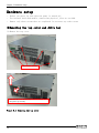
◆Removing the top cover and drive bay
(1) Remove the top cover.
The four screws
Slide the case cover horizontally as far as it will go, and
then pull it up vertically.
Figure 3.1
14
Removing the top cover
User’s Manual
Chapter3 Hardware setup
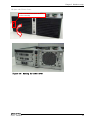
(2) Open the Front Cover.
Push on the latch and remove the front
front horizontally.
Figure 3.2
User’s Manual
Opening the front cover
15
Chapter3 Hardware setup
(3) Remove the bracket for the riser card.
The three screws remove
Figure 3.3
16
Removing the riser card bracket
User’s Manual
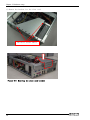
Chapter3 Hardware setup
◆Locations and settings of internal connectors and jumpers
Once you have removed the case cover, the bracket for the riser card, and the drive bay
unit, you will be able to see the connectors and jumpers as illustrated below.
Figure 3.4 Locations and setting of jumpers and connectors inside the top cover
User’s Manual
17
Chapter3 Hardware setup
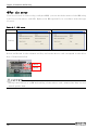
Table 3.1
Name
Factory Setting
Reference page
3-4 Short
19
CLROM1
Chassis Intrusion
Connector
Clear CMOS
1-2 Short
19
CLRTC1
Clear ROM
1-2 Short
20
JRS4
Serial Port Setting
1-2 Short
20
JRS5
Serial Port Setting
20
JRS6
Serial Port Setting
2-4,3-5,8-10,9-11,14-16,
15-17,20-22,21-23 Short
OPEN
CHASSIS1
Table 3.2
Function
Remarks
-
Connector list
Name
Function
ATX12V1
ATX 12V power supply connector
F_PANEL1
EATXPWR1
ATX 24Pin power supply connector
USB56
Internal USB 5,6 connector
USB78
Remarks
Name
Function
Remarks
Internal USB 7,8 connector
Front panel connector
FLOPPY
Floppy disk connector
JDIO1
Degital I/O connector
PRI_IDE1
Primary IDE connector
JDIO2
Sirial connector
SATA1-4
Serial ATA 1/2/3/4 connector
SPDIF01
SPDIF connector
COM2-4
Serial Port 2/3/4 connector
XBT2
18
Jumper setting
CMOS Battery connector
AAFP1
PWR_FAN1
※3
Internal Audio connector
Chassis FAN connector
User’s Manual
Chapter3 Hardware setup
◆Jumper setting
■Chassis Intrusion : CHASSIS1
Use the factory default settings.
Table 3.3
CHASSIS1 setting
CHASSIS1
1
2
3
Function
4
State usually
(Factory default setting)
■ CMOS clear setting:CLRTC
CMOS Clear will reset the contents of the CMOS to initial BIOS values. Clearing the CMOS
will not reset the clock.
Table 3.4
CMOS clear setting
CLRTC
Function
1
2
3
1
2
3
State usually
(Factory default setting)
CMOS clear
Always set CMOS Clear with the AC cable unplugged, and before reconnecting the power,
restore it to its normal setting.
Clearing the CMOS while the power is connected may damage the board.
User’s Manual
19
Chapter3 Hardware setup
■ROM clear setting:CLROM1
As this is a system-reserved jumper, its setting cannot be changed.
Use the factory default settings.
Table 3.5
ROM clear setting
CLROM1
1
Function
2
3
State usually
(Factory default setting)
■Serial port setting:JRS4
As this is a system-reserved jumper, its setting cannot be changed.
Use the factory default settings.
Table 3.6
JRS4 setting
JRS4
2
4
6
Function
8
10
State usually
(Factory default setting)
1
3
5
7
9
■Serial port setting:JRS5
As this is a system-reserved jumper, its setting cannot be changed.
Use the factory default settings.
Table 3.7
JRS5 setting
JRS5
2
4
6
8
10
12
14
16
18
Function
20
22
24
State usually
(Factory default setting)
1
20
3
5
7
9
11
13
15
17
19
21
23
User’s Manual
Chapter3 Hardware setup
■Attach the hard disk
(1) Remove the 3.5inch bay from the drive bay.
Loosen thes screws
Figure3.5 Remove the drive bay
User’s Manual
21
Chapter3 Hardware setup
(2) Attch the HDD in the removed 3.5inch bay.
①How to attch the 3.5inch HDD
Tighten inch flat head screw from the side of
3.5inch bay
( four in total including the other side)
Figure3.6 Attach the 3.5inch HDD in the bay
②How to attch the 2.5inch HDD
Tighten inch flat head screw from the
bottom of 3.5inch bay
Figure3.7 Attach the 2.5inch HDD in the bay
(3) Attach the 3.5inch bay by reversing the removal procedure.
22
User’s Manual
Chapter3 Hardware setup
■Attach the extension board
(1) Remove the slot cover from the removed riser card.
Screws
Figure 3.8 Remove the slot cover
User’s Manual
23
Chapter3 Hardware setup
(2) Install a PCI extension board.
PCI extension board
The upper row extended slot
The lower row extended slot
Push in the PCI extension board securely as
far as it will go.
Figure 3.9 Attach the expansion board
(3) Tighten screws and install the riser card bracket in the case.
Please install it very carefully might interface with the bend of various cables in the
case when you install it according to the size of the extension board that installs it.
■Maximum dimensions of boards that can be installed:
174mm(L)×106mm(H)
24
User’s Manual
Chapter3 Hardware setup
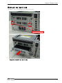
■Replacing the front fan unit and fan filter
(1) Remove the front fan unit from the case.
Loosen thes screws
Figure 3.10 Remove the front fan unit
User’s Manual
25
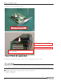
Chapter3 Hardware setup
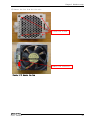
(2) Remove the fan filter unit from the fan unit.
Figure 3.11 Remove the fan filter unit
(3)Remove the fan filter.
fan filter
Figure 3.12 Remove the fan filter
(4) Prepare the replacement fan filter and attach it by reversing the removal procedure.
26
User’s Manual
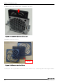
Chapter3 Hardware setup
(5) Remove the fan from the fan unit.
Loosen the screws
Remove the connector
Figure 3.13 Remove the fan
User’s Manual
27
Chapter3 Hardware setup
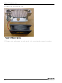
(6) Remove the fan from fan unit.
Figure 3.14 Remove the fan
(7) Prepare the replacement fan and attach it by reversing the removal procedure.
28
User’s Manual
Chapter3 Hardware setup
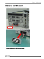
■Replacing the CMOS battery
(1) Remove the screws from the CMOS battery bracket.
screw
Figure 3.15 Remove the CMOS battery bracket
User’s Manual
29
Chapter3 Hardware setup
(2) Cut the lock anchoring the battery and remove the battery.
Cut the lock tie
-
+
Figure 3.16 Remove the CMOS battery
30
User’s Manual
Chapter3 Hardware setup
(3) Prepare the replacement CMOS battery and attach it by reversing the removal procedure.
-
+
Confirm the positive poles and negative
poles, and insert the battery.
Figure 3.17 Attach the CMOS battery
■CMOS Battery Specification
Type:CR2/3A
Voltage:3V
Capacity:1350 mAh
User’s Manual
31
Chapter3 Hardware setup
■Option: Attach the vertical stand
(1) Secure with six screws attached to the side of the case.
screw
Figure 3.18 Attach the vertical stand
32
User’s Manual
Chapter3 Hardware setup
■Option: Attach the horizontal installation bracket
(1) Secure with six screws attached to the bottom of the case.
screw
Figure 3.19
User’s Manual
Attach the horizontal installation bracket
33
Chapter3 Hardware setup
■Installation requirements
In order to enjoy reliable use of the VPC-1500 series, maintain the following conditions.
(1)
Installable directions
Installation should be done according to the following directions.
Installation should not be done any other way.
Vertical installation
Horizontal installation
Figure 3.20 Installable direction
34
User’s Manual
Chapter3 Hardware setup
(2)
Space between the main unit and its surroundings
The main unit of the VPC-1500 series is equipped with air vents and fans for
regulating temperature.
In order to ensure space for air vents and cables, keep a distance of 100mm or further
between the front/rear and surrounding equipment, walls, etc.
Note that in the installation location, air must be able to circulate.
The unit cannot be used in an enclosed space.
【背面】
【Rear】
100m
m or m
ore
100mm
以上
100mm or
more
以上
100mm
【Front】
【前面】
The arrow is a flow of air.
※
※矢印は空気の流れ
Figure 3.21 Installation condition
User’s Manual
35
Chapter3 Hardware setup
36
User’s Manual
Chapter4 BIOS setup
Chapter4 BIOS setup
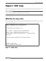
BIOS setup sets various setting during startup. When using the system for the first time,
besure to run BIOS setup. Once set up, the specified details will be backed up.
Do not change items not described in this document.
The system may become unstable and may not start up.
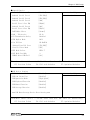
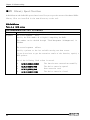
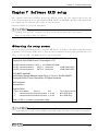
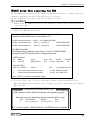
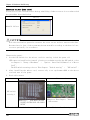
◆Starting the setup screen
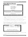
When you turn on the power to the system, if the system is functioning normally, the “Press
DEL to enter SETUP” screen appears. Then press the <DEL> key. After a few seconds, a setup
utility can be started.
Phoenix - AwardBIOS v6.00PG, An Energy Star Ally
Copyright © 1984-2009, Phoenix Technologies, LTD
VPC-1500 BIOS Ver1.00 CONTEC Co.,Ltd.
Main Processor : Intel(R) Core™2 Duo 2.99GHz(333x9.0)
Memory Testing : 4092864K OK+ 32M shared memory
CPU Brand Name : Intel(R) Core(TM)2 Duo CPU
E8400 @ 3.00GHz
EM64T CPU
Memory Frequency For DDR3 1066 (Dual Channel Mode)
Press DEL to enter SETUP
04/07/2011-Eaglelake-0A79WCL9C-00
Figure 4.1
User’s Manual
Initial screen
37
Chapter4 BIOS setup
◆Key operation
This section provides a list of major key-bound functions during setup.
Table 4.1
Key operation list
Key
Up Arrow
Down Arrow
Left Arrow
Right Arrow
Function
Move to the previous item
Move to the next item
Move to the item on the left (menu bar)
Move to the item on the right (menu bar)
Main Menu:Quit without saving changes
Submenus:Exit Current page to the next higher
level menu
ESC
Move Enter Move to the item you desired
PgUp key Increase the numeric value or make changes
PgDn key Decrease the numeric value or make changes
+ key
Increase the numeric value or make changes
- key
Decrease the numeric value or make changes
Main Menu:Quit and not save changes into CMOS
Status Page Setup Menu and Option Page Setup Menu:
ESC key Exit current page and return to Main Menu
F1 key
General help on Setup navigation keys
F5 key
Load previous values from CMOS
F6 key
Load the fail-safe defaults from BIOS default table
F7 key
F10 key
38
Load the optimized defaults
Save all the CMOS changes and exit
User’s Manual
Chapter4 BIOS setup
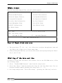
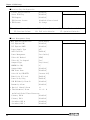
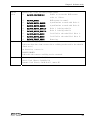
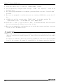
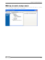
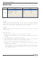
◆Main window
When you start the setup utility, the main window appears.
¾ Standard CMOS Features
¾ Frequency/Voltage Control
¾ Advanced BIOS Features
Load Fail-Safe Defaults
¾ Advanced Chipset Features
Load Optimized Defaults
¾ Integrated Peripherals
Set Supervisor Password
¾ Security Chip Configuration
Set User Password
¾ Power Management Setup
Save & Exit Setup
¾ PnP/PCI Configurations
Exit Without Saving
¾ PC Health Status
↑ ↓ → ←: Select Item
Esc:
Quit
F10:
Save & Exit Setup
F6 :
SAVE CMOS TO BIOS
F7 : LOAD CMOS FROM BIOS
Time, Date, Hard Disk Type….
Figure 4.2
Example of main window screen
1. The cursor keys <↑>, <↓>, <→>, <←> allow you to navigate through menu items and
the <Enter> key allows you to choose among them.
2. After pressing the <F10> key, you can save the current settings by pressing the <Enter>
key or the <Y> key.
◆Setting of the date and time
In order to set the date and time of the calendar clock on the VPC-1500 series, follow
the following steps.
1. Select “Standard CMOS Features” menu from the setup screen.
2. Select date (Date:) items by pressing the <Page Up> and <Page Down> keys. You can
navigate through items by pressing the cursor keys <←>, <→>.
3. Save setup changes with “Save & Exit Setup” (pressing the <F10> key) and exit.
User’s Manual
39
Chapter4 BIOS setup
◆Setting of the start password
After setting a startup password, you must enter the password when you boot the system
and run setup.
The password can protect system information and files, limiting their use by other users.
Once you register a password, you will not able to clear password features without
the password. Pay careful enough attention in handling your password.
1. Select “Advanced BIOS Features” menu from the setup screen.
2. For “Security Option”, select “Setup” or “System”.
Setting of the security Option
Setup
System
Operation
CMOS setup is protected by a password.
In addition to the above, system boot is protected by
a password.
3. For “Set User Password”, press the <Enter> key and enter a password.
4. Save setup changes with “Save & Exit Setup” and exit.
In addition to User Passwords, you can also set an Administrator Password. Operation during
CMOS setup differs as follows, although operation at system startup is the same.
Setting of the
password
User
Administrator
Operating at the CMOS setup
You can access all settings, but you cannot modify any setting
other than removing your password.
You can change all settings.
◆Release of setted the password
With the Setup Password set, items whose contents cannot be changed in the CMOS Setup appear.
Before changing settings in the CMOS Setup, always remove the User Password. (Although
the method for doing this is the same as setting a password, when you enter the password,
press the <Enter> key without entering anything, and the password will be removed. Removing
the Administrator Password works the same way.)
40
User’s Manual
Chapter4 BIOS setup
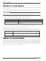
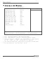
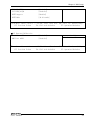
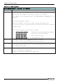
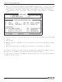
◆Changing to the device boot order
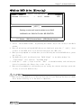
It is possible to change device boot order.
Advanced BIOS Features
¾ CPU Feature
[Press Enter]
¾ Hard Disk Boot Priority
[Press Enter]
Virus Warning
[Disabled]
CPU L3 Cache
[Enabled]
Quick Power On Self Test
[Enabled]
USB Device Wait
[Disabled]
First Boot Device
[CDROM]
Second Boot Device
[Hard Disk]
Third Boot Device
[Disabled]
Boot Other Device
[Enabled]
Swap Floppy Drive
[Disabled]
Boot Up Floppy Seek
[Disabled]
Boot Up NumLock Status
[On]
Gate A20 Option
[Fast]
Typematic Rate Setting
[Disabled]
x Typematic Rate (Chars/Sec)
x Typematic Delay (Msec)
APIC Mode
[Enabled]
Enter: Select
¾
250
[Setup]
F5: Previous Values
Menu Level
6
Security Option
↑↓→←Move
Item Help
+/-/PU/PD: Value
F10: Save
F6: Fail-safe defaults
ESC: Exit
F1: General Help
F7: Optimized Defaults
1. Select “Advanced BIOS Features” menu from the main window.
2. Change the settings for “First Boot Device”, “Second Boot Device”, and “Third
Boot Device”.
3. In order to assign top priority to booting from the CD-ROM, move the cursor to the
item to the right of “First Boot Device” and change the setting to “CDROM”. (Confirm
your choice and setting by pressing the <Enter> key.)
4. After setting the desired order, press the <Esc> key and return to the Main window.
5. Save setup changes with “Save & Exit Setup” and exit.
The software RAID, you must select “P0-Optiarc DVD” in place of “CDROM” for the device name.
User’s Manual
41
Chapter4 BIOS setup
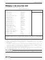
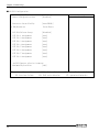
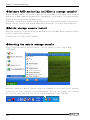
◆ Selecting to the IDE device
OnChip IDE Device
IDE HDD Block Mode
[Enabled]
IDE DMA transfer access
[Enabled]
IDE Primary Master PI0
[Auto]
IDE Primary Slave
[Auto]
PI0
IDE Primary Master UDMA
[Auto]
IDE Primary Slave
[Auto]
UDMA
On-Chip Secondary PCI IDE
[Enabled]
IDE Secondary Master PI0
[Auto]
IDE Secondary Slave
[Auto]
PI0
IDE Secondary Master UDMA
[Auto]
IDE Secondary Slave
[Auto]
UDMA
Item Help
Menu Level
SATA Mode
[IDE]
LEGACY Mode Support
[Disabled]
↑↓→←Move
Enter: Select
F5: Previous Values
+/-/PU/PD: Value
F10: Save
F6: Fail-safe defaults
ESC: Exit
¾
F1: General Help
F7: Optimized Defaults
1. Select “Integrated Peripherals” menu from the main window.
2. Select “OnChip IDE Device” menu from “Integrated Peripherals” windows.
3.
Change the settings for “SATA Mode” from “OnChip IDE Device” window. (Options
are “IDE”, “RAID”, and “AHCI”, but AHCI mode is not supported.)
4. After setting the desired order, press the <Esc> key and return to the Main window.
5. Save setup changes with “Save & Exit Setup” and exit.
42
User’s Manual
Chapter4 BIOS setup
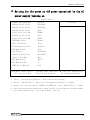
◆ Setting for the power on (AT power operation) by the AC
power-supply turning on
SuperIO Device
Onboard FDC Controller
[Enabled]
Onboard Serial Port 1
[3F8/IRQ4]
Onboard Serial Port 2
[2F8/IRQ3]
Onboard Serial Port 3
[2A0]
Serial Port 3 Use IRQ
[IRQ10]
Onboard Serial Port 4
[2A8]
Serial Port 4 Use IRQ
[IRQ11]
UART Mode Select
[Normal]
x RxD , TxD Active
Hi,Lo
x IR Transmission Delay
Enabled
x UR2 Duplex Mode
Half
x Use IR Pins
[378/IRQ7]
Parallel Port Mode
[SPP]
x EPP Mode Select
EPP1.7
x ECP Mode Use DMA
3
↑↓→←Move
Enter: Select
F5: Previous Values
Menu Level
¾
IR-Rx2Tx2
Onboard Parallel Port
PWRON After PWR-Fail
Item Help
[Off]
+/-/PU/PD: Value
F10: Save
ESC: Exit
F6: Fail-safe defaults
F1: General Help
F7: Optimized Defaults
1. Select “Integrated Peripherals” menu from the main window.
2. Select “SuperIO Device” menu from “Integrated Peripherals” windows.
3. Change “On” the settings for “PWRON After PWR-Fall” from “SuperIO Device” window.
4. After setting the above-mentioned 3, press the <Esc> key and return to the Main window.
5. Save setup changes with “Save & Exit Setup” and exit.
User’s Manual
43
Chapter4 BIOS setup
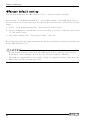
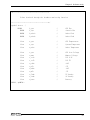
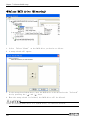
◆Factory default setting
This section describes the CMOS Setup Utility’s factory default settings.
By selecting “Load Optimized Defaults” in the Main window of the CMOS Setup Utility,
you can restore our factory settings. For operational instructions, follow the following
steps.
1. Select “Load Optimized Defaults” menu from the setup screen.
2. You are prompted to confirm that you are restoring to initial conditions. Press the
<Y> and <Enter> keys.
3. Save setup changes with “Save & Exit Setup” and exit.
The following section describes parameters for the factory default settings of each setting
in the CMOS Setup Utility.
Do not change settings other than the CMOS Setup Utility settings specifically
described in this document. The OS may not function normally otherwise.
We assume no responsibility for trouble caused by changing settings other than the
CMOS Setup Utility settings specified.
44
User’s Manual
Chapter4 BIOS setup
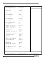
■Standard CMOS Features
Date (mm:dd:yy)
***, *** ** ****
Time (hh:mm:ss)
** : ** : **
¾ IDE Channel 0 Master
[None]
¾ IDE Channel 0 Slave
[None]
¾ IDE Channel 1 Maste
[None]
¾ IDE Channel 1 Slave
[None]
¾ IDE Channel 2 Maste
[None]
Menu Level
Drive A
[None]
Drive B
[None]
Video
[EGA/VGA]
Halt On
[All , But Disk/Key]
Base Memory
4091904K
Total Memory
4091904K
Enter: Select
F5: Previous Values
¾
639K
Extended Memory
↑↓→←Move
Item Help
+/-/PU/PD: Value
F10: Save
F6: Fail-safe defaults
ESC: Exit
F1: General Help
F7: Optimized Defaults
※ As the Standard CMOS features differ according to date and PC configuration, the above
figure is a sample.
User’s Manual
45
Chapter4 BIOS setup
■Advanced BIOS Features
¾ CPU Feature
[Press Enter]
¾ Hard Disk Boot Priority
[Press Enter]
Virus Warning
[Disabled]
CPU L3 Cache
[Enabled]
Quick Power On Self Test
[Enabled]
USB Device Wait
[Disabled]
First Boot Device
[CDROM]
Second Boot Device
[Hard Disk]
Third Boot Device
[Disabled]
Boot Other Device
[Enabled]
Swap Floppy Drive
[Disabled]
Boot Up Floppy Seek
[Disabled]
Boot Up NumLock Status
[On]
Gate A20 Option
[Fast]
Typematic Rate Setting
[Disabled]
x Typematic Rate (Chars/Sec)
x Typematic Delay (Msec)
APIC Mode
[Enabled]
MPS Version Control For OS
[1.4]
OS Select For DRAM > 64MB
[Non-OS2]
Report No FDD For WIN 95
Enabled
[Yes]
Small Logo(EPA) Show
[Disabled]
ASF support
[Enabled]
DMI Event Log
[Enabled]
Clear All DMI Event Log
[No]
View DMI Event Log
[Enter]
Mark DMI Events as Read
[Enter]
Event Log Capacity
Space Available
Event Log Validity
Valid
Enter: Select
F5: Previous Values
46
Disabled
19200
Agent after boot
↑↓→←Move
¾
250
[Setup]
Console Redirection
Menu Level
6
Security Option
x Baud Rate
Item Help
+/-/PU/PD: Value
F10: Save
F6: Fail-safe defaults
ESC: Exit
F1: General Help
F7: Optimized Defaults
User’s Manual
Chapter4 BIOS setup
●CPU Feature
PPM Mode
[Native Mode]
Limit CPUID MaxVal
[Disabled]
C1E Function
[Disabled]
Execute Disable Bit
[Enabled]
Virtualization Technology
[Disabled]
SMRR
[Disabled]
Core Multi-Processing
[Enabled]
↑↓→←Move
Enter: Select
F5: Previous Values
+/-/PU/PD: Value
Item Help
Menu Level
F10: Save
F6: Fail-safe defaults
ESC: Exit
F1: General Help
F7: Optimized Defaults
●Hard Disk Boot Priority
1. Bootable Add-in Cards
Item Help
Menu Level
↑↓→←Move
Enter: Select
F5: Previous Values
※
¾
+/-/PU/PD: Value
F10: Save
F6: Fail-safe defaults
ESC: Exit
¾
F1: General Help
F7: Optimized Defaults
As values differ according to your PC environment, the above is a sample.
User’s Manual
47
Chapter4 BIOS setup
■Advanced Chipset Features
System BIOS Cacheable
[Enabled]
Memory Hole At 15M-16M
[Disabled]
Item Help
Menu Level
¾PCI Express Root Port Func
[Press Enter]
¾Advanced Fan Speed Contorl
[Press Enter]
Disable MCHBAR MMIO
[Enabled]
VT-d
[Disabled]
¾Intel AMT Configuration
¾
[Press Enter]
** VGA Setting **
PEG/Onchip VGA Control
[Auto]
On-Chip Frame Buffer Size
[ 32MB]
DVMT Mode
[Enabled]
Total GFX Memory
[128MB]
PAVP Mode
[Lite]
↑↓→←Move
Enter: Select
F5: Previous Values
●PCI Express Root Port Func
PCI Express Port 1
[Auto]
[Auto]
PCI Express Port 4
[Auto]
PCI Express Port 5
[Auto]
PCI Express Port 6
[Auto]
PCI-E Compliancy Mode
[v1.0a]
Enter: Select
ESC: Exit
+/-/PU/PD: Value
F1: General Help
F7: Optimized Defaults
[Auto]
PCI Express Port 3
F5: Previous Values
F10: Save
F6: Fail-safe defaults
PCI Express Port 2
↑↓→←Move
48
+/-/PU/PD: Value
Item Help
Menu Level
F10: Save
F6: Fail-safe defaults
ESC: Exit
¾
F1: General Help
F7: Optimized Defaults
User’s Manual
Chapter4 BIOS setup
●Advanced Fan Speed Control
Fan1 Speed Monitor
[Enabled]
Fan2 Speed Monitor
[Enabled]
Fan3 Speed Monitor
[Enabled]
↑↓→←Move
Enter: Select
F5: Previous Values
●Intel AMT Configuration
AMT BIOS Support
+/-/PU/PD: Value
IDE-R Support
Enabled
Platform Mng Selection
Intel AMT
QST Support
Disabled
[Disabled]
OEM Flag BIT1
[Disabled]
OEM Flag BIT2
[Disabled]
F5: Previous Values
¾
F1: General Help
F7: Optimized Defaults
Item Help
Menu Level
¾
Disabled
OEM Flag BIT0
Enter: Select
ESC: Exit
[Disabled]
Enabled
↑↓→←Move
F10: Save
F6: Fail-safe defaults
SOL Support
Danbury Technology
Item Help
Menu Level
+/-/PU/PD: Value
F10: Save
F6: Fail-safe defaults
ESC: Exit
F1: General Help
F7: Optimized Defaults
■Integrated Peripherals
¾ OnChip IDE Device
[Press Enter]
¾ Onboard Device
[Press Enter]
¾ SuperIO Device
[Press Enter]
¾ USB Device Setting
[Press Enter]
↑↓→←Move
Enter: Select
F5: Previous Values
User’s Manual
+/-/PU/PD: Value
F10: Save
F6: Fail-safe defaults
Item Help
Menu Level
ESC: Exit
¾
F1: General Help
F7: Optimized Defaults
49
Chapter4 BIOS setup
●OnChip IDE Device
IDE HDD Block Mode
[Enabled]
IDE DMA transfer access
[Enabled]
IDE Primary Master PIO
[Auto]
IDE Primary Slave
[Auto]
PIO
IDE Primary Master UDMA
[Auto]
IDE Primary Slave
[Auto]
UDMA
On-Chip Secondary PCI IDE
[Enabled]
IDE Secondary Master PIO
[Auto]
IDE Secondary Slave
[Auto]
PIO
IDE Secondary Master UDMA
[Auto]
IDE Secondary Slave
[Auto]
UDMA
SATA Mode
[IDE]
LEGACY Mode Support
[Disabled]
↑↓→←Move
Enter: Select
F5: Previous Values
●Onboard Device
Onboard LAN
+/-/PU/PD: Value
Item Help
Menu Level
F10: Save
F6: Fail-safe defaults
ESC: Exit
F1: General Help
F7: Optimized Defaults
[Enabled]
Item Help
Menu Level
↑↓→←Move
Enter: Select
F5: Previous Values
50
+/-/PU/PD: Value
¾
F10: Save
F6: Fail-safe defaults
ESC: Exit
¾
F1: General Help
F7: Optimized Defaults
User’s Manual
Chapter4 BIOS setup
●SuperIO Device
Onboard FDC Controller
[Enabled]
Onboard Serial Port 1
[3F8/IRQ4]
Onboard Serial Port 2
[2F8/IRQ3]
Onboard Serial Port 3
[2A0]
Serial Port 3 Use IRQ
[IRQ10]
Onboard Serial Port 4
[2A8]
Serial Port 4 Use IRQ
[IRQ11]
UART Mode Select
[Normal]
x RxD , TxD Active
Hi,Lo
x IR Transmission Delay
Enabled
x UR2 Duplex Mode
Half
x Use IR Pins
IR-Rx2Tx2
Onboard Parallel Port
[378/IRQ7]
Parallel Port Mode
[SPP]
x EPP Mode Select
x ECP Mode Use DMA
PWRON After PWR-Fail
↑↓→←Move
Enter: Select
F5: Previous Values
Item Help
Menu Level
¾
EPP1.7
3
[Off]
+/-/PU/PD: Value
F10: Save
F6: Fail-safe defaults
●USB Device Setting
USB 1.0 Controller
[Enabled]
USB 2.0 Controller
[Enabled]
USB Operation Mode
[High Speed]
USB Keyboard Function
[Enabled]
USB Mouse Function
[Enabled]
USB Storage Function
[Enabled]
ESC: Exit
F1: General Help
F7: Optimized Defaults
Item Help
Menu Level
¾
*** USB Mass Storage Device Boot Setting ***
↑↓→←Move
Enter: Select
F5: Previous Values
User’s Manual
+/-/PU/PD: Value
F10: Save
F6: Fail-safe defaults
ESC: Exit
F1: General Help
F7: Optimized Defaults
51
Chapter4 BIOS setup
■Security Chip Configuration
LT/TXT Initialization
[Disabled]
Reset TPM Flag
[Disabled]
TPM Support
[Disabled]
TPM Current Status
x TPM Status
↑↓→←Move
Item Help
Menu Level
¾
Disabled & Deactivated
No change
Enter: Select
F5: Previous Values
+/-/PU/PD: Value
F10: Save
F6: Fail-safe defaults
ESC: Exit
F1: General Help
F7: Optimized Defaults
■Power Management Setup
¾PCI Express PM Function
[Press Enter]
PCI Express PME
[Disabled]
PCI Express WAKE
[Disabled]
Power-Supply Type
[AT]
ACPI Function
[Enabled]
Power Management
[User Define]
Video Off Method
[DPMS]
Video Off In Suspend
[Yes]
Suspend Type
[Stop Grant]
MODEM Use IRQ
[3]
Suspend Mode
[Disabled]
HDD Power Down
[Disabled]
Soft-Off by PWR-BTTN
[Instant-Off]
Wake-Up by PCI card
[Enabled]
Power On by Ring
[Enabled]
USB KB Wake-Up From S3
[Disabled]
Resume by Alarm
[Disabled]
x Date(of
Month) Alarm
Item Help
Menu Level
¾
0
x Time(hh:mm:ss) Alarm
0 : 0 : 0
** Reload Global Timer Events **
52
Primary IDE 0
[Disabled]
Primary IDE 1
[Disabled]
Secondary IDE 0
[Disabled]
Secondary IDE 1
[Disabled]
User’s Manual
Chapter4 BIOS setup
FDD,COM,LPT Port
[Disabled]
PCI PIRQ[A-D]#
[Disabled]
HPET Support
[Enabled]
HPET Mode
[32-bit mode]
↑↓→←Move
Enter: Select
F5: Previous Values
●PCI Express PM Function
Root Port ASPM
DMI Port ASPM
↑↓→←Move
Enter: Select
F5: Previous Values
User’s Manual
+/-/PU/PD: Value
F10: Save
F6: Fail-safe defaults
[Disabled]
F1: General Help
F7: Optimized Defaults
Item Help
Menu Level
¾
[Disabled]
+/-/PU/PD: Value
ESC: Exit
F10: Save
F6: Fail-safe defaults
ESC: Exit
F1: General Help
F7: Optimized Defaults
53
Chapter4 BIOS setup
■PnP/PCI Configuration
Init Display First
[PCI Slot]
Reset Configuration Data
[Disabled]
Resources Controlled By
[Auto(ESCD)]
x IRQ Resources
Item Help
Menu Level
¾
Press Enter
PCI/VGA Palette Snoop
[Disabled]
INT Pin 1 Assignment
[Auto]
INT Pin 2 Assignment
[Auto]
INT Pin 3 Assignment
[Auto]
INT Pin 4 Assignment
[Auto]
INT Pin 5 Assignment
[Auto]
INT Pin 6 Assignment
[Auto]
INT Pin 7 Assignment
[Auto]
INT Pin 8 Assignment
[Auto]
** PCI Express relative items **
Maximum Payload Size
↑↓→←Move
Enter: Select
F5: Previous Values
54
[128]
+/-/PU/PD: Value
F10: Save
F6: Fail-safe defaults
ESC: Exit
F1: General Help
F7: Optimized Defaults
User’s Manual
Chapter4 BIOS setup
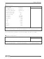
■PC Health Status
CPU Warning Temperature
[Disabled]
Warning BEEP
[Disabled]
CPU THRM-Throttling
[Disabled]
Smart Fan1 Temperature
[50℃/122°F]
Fan1 Tolerance Value
[ 1]
Current System Temp.
34℃
Current CPU Temp.
38℃
Fan1 Speed
5869 RPM
Fan2 Speed
2700 RPM
Fan3 Speed
0 RPM
Vcore
1.22V
+12 V
12.15V
+ 5 V
4.93V
VBAT (V)
3.28V
3VSB (V)
3.42V
↑↓→←Move
Enter: Select
F5: Previous Values
+/-/PU/PD: Value
Item Help
Menu Level
F10: Save
F6: Fail-safe defaults
ESC: Exit
¾
F1: General Help
F7: Optimized Defaults
※ As values differ according to your PC environment, the above is a sample.
■Frequency/Voltage Control
Spread Spectrum
[Enabled]
Item Help
Menu Level
↑↓→←Move
Enter: Select
F5: Previous Values
User’s Manual
+/-/PU/PD: Value
F10: Save
F6: Fail-safe defaults
ESC: Exit
¾
F1: General Help
F7: Optimized Defaults
55
Chapter4 BIOS setup
56
User’s Manual
Chapter5 Each component function
Chapter5 Each component function
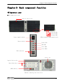
◆Component name
■VPC-1500 front view
Optical drive unit
Drive2 LED
Drive1 LED
Access LED
Power supply switch
※Use hardware RAID models only
Reset switch
Power LED
HDD LED
User LED1
User LED2
USB connector
Cooler fan
Optical drive unit
Hard disk drive
CMOS battery
※After removing the front face
User’s Manual
57
Chapter5 Each component function
■VPC-1500 rear view
Digital I/O connector
COM4
PCI×3
COM3
COM2
AC inlet
Mother board interface
FG terminal
Mouse connector
Ethernet connector
Printer port connector
Line In
Line Out
Mic In
Keyboard connector
58
COM1
CRT connector
USB connector
User’s Manual
Chapter5 Each component function
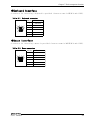
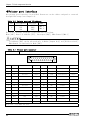
◆Keyboard interface
A connector for connecting a keyboard is provided. Connector name is KB(6Pin mini-DIN).
Table 5.1
Keyboard connector
6
5
4
3
2
1
ピン番号
Pin No.
機能
Function
1
K.B DATA
2
N.C.
3
GND
4
+5V
5
K.B CLOCK
6
N.C.
◆Mouse interface
A connector for connecting a mouse is provided. Connector name is MOUSE(6Pin mini-DIN).
Table 5.2
Mouse connector
6
5
4
3
2
User’s Manual
1
ピン番号
Pin No.
機能
Function
1
MOUSE DATA
2
N.C.
3
GND
4
+5V
5
MOUSE CLOCK
6
N.C.
59
Chapter5 Each component function
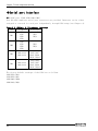
◆Serial port interface
■RS-232C port (COM1,COM2,COM3,COM4)
Four RS-232C-compliant serial port connectors are provided. Resources can be either
assigned or reserved for each port independently through BIOS setup (see Chapter 4).
Table 5.3 SERIAL1, 2 I/O address、interrupt
COM
I/O Address
Interrupt
3F8h
IRQ3
2F8h
COM1
IRQ4
3E8h
2E8h
3F8h
2F8h
IRQ3
COM2
3E8h
IRQ4
2E8h
IRQ3,IRQ4
280h,288h
IRQ5,IRQ7
COM3
2A0h,2A8h
IRQ9,IRQ10
IRQ11,IRQ12
IRQ3,IRQ4
280h,288h
IRQ5,IRQ7
COM4
2A0h,2A8h
IRQ9,IRQ10
IRQ11,IRQ12
The factory default settings of the BIOS are as follows.
COM1(3F8h),IRQ4
CON2(2F8h),IRQ3
COM3(2A0h),IRQ10
COM4(2A8h),IRQ11
60
User’s Manual
Chapter5 Each component function
Table 5.4
Serial port connector
D-SUB 9 芯
pin(MALE)
(MALE)
本体使用コネクタ
Connector
1
5
No.4-40UNC
インチネジ
Inch
screw
9
6
ピン番号
Pin No.
信号名
Signal
1
CD
キャリア検出
C
areer detection
2
RD
受信データ
Receive data
3
TD
ransmission data
T送信データ
O出力
utput
O出力
utput
方向
Direction
意味
Function
入力
Input
入力
Input
4
DTR
データターミナルレディ
D
ata terminal ready
5
GND
信号グラウンド
Si
gnal ground
6
DSR
データセットレディ
Data set ready
7
RTS
送信要求
Transmission request
8
CTS
送信可
Ready of sending
入力
In
put
9
RI
被呼表示
Ring indication
入力
In
put
----入力
In
put
O出力
utput
◆CRT interface
A connector for connecting a CRT is provided. Connector name is VGA(15PinD-SUB).
Table 5.5
CRT connector
ピン番号
機能
ピン番号
機能
Pin
No. Function
Pin No. Function
5
1
10
6
15
User’s Manual
11
1
RED
9
N.C.
2
GREEN
10
GND
3
BLUE
11
D-DATA
4
N.C.
12
N.C.
5
GND
13
H-SYNC
6
GND
14
V-SYNC
7
GND
15
D-DCLK
8
GND
61
Chapter5 Each component function
◆Printer port interface
One printer port interface is provided. Resources can be either assigned or reserved
through BIOS setup (see Chapter 4).
Table 5.6 Printer port and I/O address
LPT
I/O Address
Interrupt
DMA
378
IRQ7
DMA 1
1
278
IRQ5
DMA 3
IRQ7
3BC
The factory default settings of the BIOS are as follows.
Mode:[SPP]、Base I/O address:[378]、Interrupt:[IRQ7]、DMA Channel:[DMA 3]
I/O address [3BC] can be selected only in Modes [Output Only] and [Bi-Directional].
DMA Channel is used only in Mode [ECP].
Table 5.7
Printer port connector
Connector
D-SUB 25 pin (FEMALE)
13
1
25
14
Pin No.
Signal
Function
Direction
Pin No.
Signal
Function
Direction
1
-STRB
Data effective
Output
14
-AFEED
Automatic field
Output
2
D0
Data bit0
Output
15
-ERROR
Not use
Input
3
D1
Data bit1
Output
16
-INIT
Initialization
Output
4
D2
Data bit2
Output
17
-SELECT・IN
Possible for input
Output
5
D3
Data bit3
Output
18
GND
Ground
-
6
D4
Data bit4
Output
19
GND
Ground
-
7
D5
Data bit5
Output
20
GND
Ground
-
8
D6
Data bit6
Output
21
GND
Ground
-
9
D7
Data bit7
Output
22
GND
Ground
-
10
-ACK
Possible for recieve
Input
23
GND
Ground
-
11
BUSY
Busy
Input
24
GND
Ground
-
12
PE
Non-paper
Input
25
GND
Ground
-
13
SELECT
Select state
Input
-
Fixed screw : No.4-40UNC inch screw
62
User’s Manual
Chapter5 Each component function
◆Reset switch
Push this button when resetting hardware.
◆Power switch
Push this button at power-on. In order to turn off the power forcibly, hold it down for
four seconds or longer.
◆USB port
Six USB interfaces are provided.
Table 5.8
ピン番号
Pin No.
USB connector
B1
B4
A1
A4
信号名
Function
ピン番号
Pin
No.
信号名
Function
A1
USB0 Vcc
B1
USB1 Vcc
A2
USB0 -Data
B2
USB1 -Data
A3
USB0 +Data
B3
USB1 +Data
A4
USB0 GND
B4
USB1 GND
User’s Manual
63
Chapter5 Each component function
◆Ethernet
The VPC-1500 is equipped with two channels for Ethernet.
・Network type
: 10BASE-T/100BASE-TX/1000BASE-T
・Transmission speed
: 10M/100M/1000Mbps
・Max. network path length
: 100m/segment
・Controller
: Intel 82567 ×1,Realtek 8111D ×1
* 1000Mbps operation requires a cable of category 5E or greater.
Table 5.9
Ethernet connector
Connector type
RJ-45
LINK/ACT
10/100/1000M
8
1
Pin No.
Signal name
Function
1
TD+
Transmission data(+)
2
TD-
Transmission data(-)
3
RD+
Receive data(+)
4
GND
Ground
5
GND
Ground
6
RD-
Receive data(-)
7
GND
Ground
8
GND
Ground
LEDs for display of network statuses
LINK/ACT LED
:(Orange) Lighting at the normal connection.
(Orange) Blinking at the data transmission and receive.
10/100/1000M LED
:Turning off at the 10M operation.
(Green) Lighting at the 100M operation.
(Orange) Lighting at the 1000M operation.
64
User’s Manual
Chapter5 Each component function
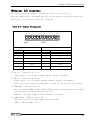
◆Digital I/O interface
This interface controls digital I/O with two rows of six pins (J2, J3).
Among the eight DIO pins, two output pins (O2, O3) are used for the user LED on the front.
The digital I/O interface is internally insulated.
Table 5.10
Digital I/O connector
1
6
JDIO1
7
12
JDIO2
JDIO1
Pin No.
JDIO2
Signal
Pin No.
Signal
1
I0
7
O0
2
I1
8
O1
3
I2
9
O2 (Connected prohibition)
4
I3
10
O3 (Connected prohibition)
5
PWRON
11
COMPO
6
RST
12
COMPI
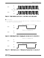
1)I0~I3 (JDIO1 Pin No. 1~4)
Input signal : You can input Input0, Input1, Input2, and Input3.
2)O0~O3 (JDIO2 Pin No. 7~10)
Output signal : You can output Output0, Output1, Output2, and Output3.
※You can not use Output2,3 because they are used for the user LED on the front.
3)PWRON,RST (JDIO1 Pin No.5,6)
Short-circuiting PWRON and GND or RST and GND triggers the same operation as pushing
the Power button or Reset button on the front.
※However, the power-supply from the outside is necessary.
4)COMPO,COMPI
(JDIO2 Pin No.11,12)
These are used for the power-supply from the outside.
COMPO is GND and COMPI is VCC.
User’s Manual
65
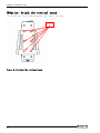
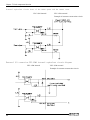
Chapter5 Each component function
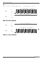
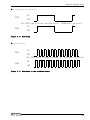
Internal equivalent circuit chart of the remote power and the remote reset
VPC-1500 internal
VPC-1500 external
Example of customer construction circuit
External I/O connection VPC-1500 internal equivalent circuit diagram
VPC-1500 internal
VPC-1500 external
Example of customer construction circuit
66
User’s Manual
Chapter5 Each component function
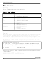
◆Audio interface
The Audio interface. is provided.
Table 5.11
Audio connector
Blue
Green
Pink
Pin No.
Signal name
Blue
Line-In
Green
Line-Out
Pink
Mic-In
User’s Manual
67
Chapter5 Each component function
68
User’s Manual
Chapter6 Software utirity
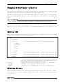
Chapter6 Software utirity
This chapter describes the driver DVD included with the VPC-1500 series. This driver DVD
includes drivers and software necessary for the VPC-1500 series.
This driver DVD does not provide Autorun functionality. Install drivers and software
manually through Windows Explorer after inserting this driver DVD into the CD/DVD-ROM
drive.
The contents of the driver DVD are subject to change without prior notice.
Pre-installed models are not accompanied by a driver DVD, and instead store driver DVD
data on a recovery DVD. A driver DVD is included with models that come without an OS.
◆Driver DVD
The directory structure of the driver DVD is shown below. The same directory is also found
on the recovery DVDs of pre-installed models.
OEM
├─Documents
├─Drivers
│
├─Audio
│
├─Chipset
│
├─Lan
│
├─Raid
│
└─Vga
← Pre-installed models have these installed in the OS.
├─IO-Lib
← Pre-installed models haven’t these installed in the OS.
├─TinyRAS
← Pre-installed models haven’t these installed in the OS.
└─HWRAID
・Documents
・Drivers
・IO-Lib
・TinyRAS
・HWRAID
← Pre-installed models haven’t these installed in the OS.
:A copy of this information is stored here.
:Versions of the installation files for the chipset, graphics,
LAN, audio, and security chip drivers are included separately for
Windows 2000, Windows XP and Windows Vista.
:Install file of general purpose I/O driver is stored here.
:Install file of RAS tool is stored here.
:Install file of hardware raid tool tool is stored here.
◆Various drivers
Install chipset, graphics, LAN, audio, and security chip drivers in the “Drivers” folder.
Since the driver to install depends on which OS is used, install the drivers appropriate
for your OS.
User’s Manual
69
Chapter6 Software utirity
◆IO-Lib
The general purpose I/O driver can be installed using the “LZF826IO_312R.EXE” in the
“IO-Lib” folder. Set it up according to the following procedure.
1. Extracting the file
Specify the destination for extracted files in the following screen and select “OK”.
2.File Directory
In the destination folder for the extracted files, files will be created using the
following directory structure.
Specification folder
├─APIPAC
├─INF
└─Readme
3.Install file
Execute setup.exe in the subfolder “\APIPAC\Runtime\IOLIB\Disk1” within the specified
folder.
4.Language select
Select a language and click “Next”.
70
User’s Manual
Chapter6 Software utirity
5.Setup
Click “Next”.
6.Choose destination location
Specify a destination folder for installation and click “Next”.
User’s Manual
71
Chapter6 Software utirity
7.Program folder
After specifying the program folder, click “Next”.
8.Completion
Click “Finish”. After clicking “Finish”, restart the PC.
Install of IO-Lib has been completed.
72
User’s Manual
Chapter6 Software utirity
Set it up according to the following procedure after IO-Lib installed.
9.Starting the IO-Lib
Selects “Start menu” – “All Programs” – “CONTEC API-PAC(W32)” – “IO-LIB(W32)”
– “IO-LIB Configuration” to start IO-Lib Configuration.
10.IO-Lib(W95/NT) Configuration
Click “OK”.
User’s Manual
73
Chapter6 Software utirity
11.Set registration
Click “OK”.
12.Completion
Click “OK”. After clicking “OK”, restart the PC.
Setup of IO-Lib has been completed.
74
User’s Manual
Chapter6 Software utirity
◆RAS tool
The RAS tool can be installed using the “TinySetup.msi” in the “TinyRAS” folder. Set
it up according to the following procedure.
1.Setup
Click “Next”.
2. Select installation folder
Select the installation destination and one of the RAS user options. Click “Next”.
User’s Manual
75
Chapter6 Software utirity
3.Confirm installation
Click “Next”.
4.Install
Installation is in progress. Completion takes some time. Wait for a while.
76
User’s Manual
Chapter6 Software utirity
5.Completion
Click “Close”. After clicking “Close”, restart the PC.
Install of RAS tool has been completed.
Set it up according to the following procedure after RAS tool installed.
6.Selecting the registry
Selects “Start menu” – “All Programs” – “CONTEC” – “TinyRAS”– “Config”
– “VPC-1500” to execute the registry.
User’s Manual
77
Chapter6 Software utirity
7.Registry addition
Click “Next”.
8.Completion
Click “OK”. After clicking “OK”, restart the PC.
Setup of RAS tool has been completed.
78
User’s Manual
Chapter6 Software utirity
◆Hardware RAID monitoring tool
This sections describes the utility which monitors the status of HDDs connected to a mirror
card. However, in order to use the utility described in this document, the following
utilities need to have been installed in Windows.
・IO-Lib
← To install this utility, refer to this chapter “Software Utility”.
・TinyRAS ← To install this utility, refer to this chapter “Software Utility”.
The latest version utirity downloads from CONTEC web site.
■Setup
The hardware raid monitoring tool can be installed using the “hwRaid.msi” in the
“HWRAID” folder. Set it up according to the following procedure.
1.Setup
Click “Next”.
User’s Manual
79
Chapter6 Software utirity
2.Select installation folder
Select the installation destination and one of the monitoring tool user options. Click
“Next”.
3.Install
Installation is in progress. Completion takes some time. Wait for a while.
80
User’s Manual
Chapter6 Software utirity
4. Complete
Click “Close”. Click “Finish”. After clicking “Finish”, restart the PC.
Install of the monitoring tool has been completed.
■Specification
Table 6.1
Tool Functional Specification
Function
Default operate
Setting range
Status
supervision
Watch interval
10min
1 ~ 65535(sec)
State
notification
LED notification
None
Check・None
Balloon notification
None
Check・None
Dialog
None
Check・None
Log
Event log
Event log・Text
State record
[Limitations]
9
It’s function depends on the user’s logon status. (It does not operate as a Windows
service.)
9
If a general-purpose I/O operation is performed by TinyRAS, operation of Lthe ED
notification function is not guaranteed.
9
If the time between occurrence of a status change and return to normal is within
the monitoring cycle, the status will not be detected.
9
The log output to an event log requires an active event log service.
9
If the install pass is different from selected installation folder, messages to the
event log will not be output properly.
User’s Manual
81
Chapter6 Software utirity
■Starting the monitoring tool
Execute hwRaid.exe. Optional strings can be specified through the command prompt or the
shortcut to hwRaid.exe.
※
For command options, refer to the information under“Command Options”.
Figure 6.1
Starting the monitoring tool
■Exit the monitoring tool
Right-click on the system tray icon to exit the utility.
Select “Exit” of the menu.
Figure 6.2
82
Exit the monitoring tool
User’s Manual
Chapter6 Software utirity
■Status
When “View Status” is selected, the following dialog appears.
(This is the same as the screen displayed through command option /status/dialog.)
MODEL, SERIAL, and
FIRM items are only
displayed when the
status
Progress bar indicating
the progress of
rebuilding (%)
Figure 6.3
Status
■Version
You can check the version information and start-up options of the monitoring tool.
Figure 6.4
Version
User’s Manual
83
Chapter6 Software utirity
■Automatic start
When Windows 2000, Windows XP Pro and Windows XP Embedded is used, create a shortcut to
hwRaid.exe in the following folder.
[Start memu]→[All programs]→[Startup]
84
User’s Manual
Chapter6 Software utirity
■Command option
You can modify operation through the following command options.
Table 6.2
Command option
Option
Content of operation
Displays only a dialog for status checks without staying
resident in the system tray.
/status
This dialog is identical to the one which can be displayed
through the system tray icon.
If the utility does not stay resident in the system tray, events
are not output.
Changes the log output destination to the specified file.
/logtext={file pass}
When this option is specified, there is no output to the event
log.
Specify this if you are going to execute an event log service
in a situation where one cannot be started.
/interval={Figure [sec]}
Changes the monitoring interval of the RAID status to the number
of seconds specified. (default setting: ten minutes intervals)
(Input range) 1 to 65535 seconds
Specifies the drive number (0 or higher) of the RAID board.
/drivenum={Figure}
Unless specified, the board functions as drive number 0.
You can check the drive number through Windows “Disk
Management”.
/balloon
This enables the display of a balloon pop-up from system tray
icon when failure is detected.
/led
This enables LED output when failure is detected.
/dialog
This enables an automatic dialog popup when failure is detected.
Execution example:(□:Space)
hwRaid.exe□/interval=10□/balloon□/led□/logtext=C:\Windows\Temp\raid.log
Notes on /status option.
If the “View Status” dialog appears with this option specified, the following
restrictions are imposed.
9
Task tray icon:Not displayed (A program does not stay resident.)
9
State notification functional:Invalidity
9
Log functional:Invalidity
9
Watch cycle:Fixation for 10sec
User’s Manual
85
Chapter6 Software utirity
■LED display
When you used command option “/led” for enable LED output, the state can be confirmed
by front LEDs. The LED of state display are user LED1 and LED2. Refer to Chapter 5 “Each
component function” – “Component name”.
●At the fault detection
Each 100 msec is blinked.
ON
LED1
OFF
State of turning off
ON
LED2
OFF
Figure 6.5
Fault detection at the drive 1
State of turning off
ON
LED1
OFF
Each 100 msec is blinked.
ON
LED2
OFF
Figure 6.6
86
Fault detection at the drive 2
User’s Manual
Chapter6 Software utirity
ON
LED1
OFF
The LED1 and 2 blinks synchronously.(100msec interval)
ON
LED2
OFF
Figure 6.7
Fault detection at the drive 1 and 2 (Error at the same sector)
●At the rebuild
When no adjustment is detected in the data under mirroring, it automatically changes to
the state of restructuring(rebuild).
Each 1000 msec is blinked.
ON
LED1
OFF
State of turning off
ON
LED2
OFF
Figure 6.8
Rebuilding the drive 1 (Copying data from the drive 2 to the drive 1)
State of turning off
ON
LED1
OFF
Each 1000 msec is blinked.
ON
LED2
OFF
Figure 6.9
User’s Manual
Rebuilding the drive 1 (Copying data from the drive 1 to the drive 2)
87
Chapter6 Software utirity
●Rebuild failure (Read error)
Refer to Chapter 8 “Hardware RAID setup” –
“Troubleshooting”, restor it.
Each 100 msec is blinked.
ON
LED1
OFF
State of turning on
ON
LED2
OFF
Figure 6.10
Drive1 read error
State of turning on
ON
LED1
OFF
Each 100 msec is blinked.
ON
LED2
OFF
Figure 6.11
88
Drive 2 read error
User’s Manual
Chapter6 Software utirity
●At restoration of read error
ON
LED1
OFF
The LED1 and 2 blinks synchronously.(1000 msec interval)
ON
LED2
OFF
Figure 6.12
Restoring
●Undefined error
ON
LED1
OFF
The LED1 and 2 blinks alternately.(100 msec interval)
ON
LED2
OFF
Figure 6.13
User’s Manual
Detection at the undefined error
89
Chapter6 Software utirity
■Log functional
[Event log]
The log is output to the event viewer application.
Table 6.3
Event log Status
Item
Warning
Error
Information
State
9
Reading error the drive 1
9
Reading error the drive 2
9
The drive 1 in fault
9
The drive 2 in fault
9
The drive 1 and 2 in fault
9
Unknown error
9
Return
9
Rebuilding the drive 1
9
Rebuilding the drive 2
9
Restoring
9
Starting at the tool
[Text log]
The text log function is only valid when a valid output file is specified through the
/logtext option. It appends the data to the specified file. It does not provide
functionality for changing the destination file or setting a ceiling on log entry count.
The delimiter is “comma” (fixed). It outputs the log to the specified file in the
following format.
Time stamp, Division, Content of log
9
Time stamp
yyyy/mm/dd(Year/Month/Day)□HH:MM:SS(Hour:Minutes:Seconds)
※ A half-width space “□” is included between year, month, day, hours, minutes,
and seconds.
9
Division
INFO, WARN, or ERR
※ The text log function is output in English regardless of the OS language environment.
(Output example)
2009/01/29 01:23:45, INFO, Start RAID Monitoring.
90
User’s Manual
Chapter6 Software utirity
[Notes]
At output of the Event log and text log, Error dialog might be displayed.
Figure 6.14 Error dialog
When error dialog is displayed, checks along the log output.
・Event log output
Checks the log setting by the property of event log application.
・Text log output
Checks the log output destination.
User’s Manual
91
Chapter6 Software utirity
■API library Specification
GetRaidStatus and GetRaidProgress functions allow you to get the status of hardware RAIDs.
Library files are installed in the same directory as the tool.
●GetRaidStatus
Table 6.4
RAID status
WORD GetRaidStatus( int Port, int *iError);
Functional
A function to get the operating status of hardware RAIDs.
Argument
The first argument
Port
Specify the disk number (0 or higher) comprising the RAID.
This number can be checked through “Disk Management (diskmgmt.msc) in
Windows.
The second argument
*iError
Specify a pointer to the int variable storing run-time errors.
If you do not have to get the execution result of the function, specify a
NULL pointer.
One of the following fixed values is stored.
92
9
RAIDLIB_ERROR_SUCESS
The function was executed successfully.
9
RAIDLIB_ERROR_OPEN
The device cannot be opened.
9
RAIDLIB_ERROR_READ
Data cannot be read.
9
RAIDLIB_ERROR_CLOSE
The device cannot be closed.
User’s Manual
Chapter6 Software utirity
Return
value
Returns one of the following fixed values.
9
RAIDSTS_INACCESSIBLE
Unable to access the RAID status.
refer to
Explanation
iError.
9
RAIDSTS_NORMAL
RAID status is normal.
9
RAIDSTS_DRIVE1_BROKEN
A problem has occured with Drive 1.
9
RAIDSTS_DRIVE2_BROKEN
A problem has occured with Drive 2.
9
RAIDSTS_DRIVE1_REBUILD
Drive 1 is being rebuilt.
9
RAIDSTS_DRIVE2_REBUILD
Drive 2 is being rebuilt.
9
RAIDSTS_DRIVE1_ERROR
It failed in the rebuild of Drive 1.
9
RAIDSTS_DRIVE2_ERROR
It failed in the rebuild of Drive 2.
9
RAIDSTS_VERIFY_CHECK
Restoring.
RAIDSTS_DRIVE(x)_ERROR
Indicates that data from a source drive coulding not be read in the rebuild.
(Read error)
At detection, restore it.
RAIDSTS_BROKEN
Indicates the restore coulding not be restored.
Remarks
Necessary header file:RaidLib.h
Static link library:RaidLib.lib
Dynamic link library:RaidLib.dll、smart.dll
User’s Manual
93
Chapter6 Software utirity
Table 6.5
RAID progress
int GetRaidProgress ( int Port, int *iError)
Functional
Argument
A function to get the progress of rebuilding.
The first argument
Port
Specify the disk number (0 or higher) comprising the RAID.
This number can be checked through “Disk Management (diskmgmt.msc) in
Windows.
The second argument
*iError
Specify a pointer to the int variable storing run-time errors.
If you do not have to get the execution result of the function, specify
a NULL pointer.
One of the following fixed values is stored.
Return value
9
RAIDLIB_ERROR_SUCESS
The function was executed successfully.
9
RAIDLIB_ERROR_OPEN
The device cannot be opened.
9
RAIDLIB_ERROR_READ
Data cannot be read.
9
RAIDLIB_ERROR_CLOSE
Data cannot be close.
-1: Error: Could not get progress. refer to iError.
0 or higher: Indicates rebuilding progress % (percent).
Explanation
When you get RAIDSTS_DRIVE(x)_REBUILD or RAIDSTS_DRIVE(x)_VERIFY_CHECK by
the RaidGetStatus function, you can get the rebuilding progress by
executing this function.
Remarks
Necessary header file:RaidLib.h
Static link library:RaidLib.lib
Dynamic link library:RaidLib.dll、smart.dll
94
User’s Manual
Chapter6 Software utirity
◆Watch-Dog Timer (WDT) Setting
You can set a watchdog timer by using tRasWdtmr function. Execute this function
periodically and program it so that the watchdog timer will not be reset.
Prototype of function
int tRasWdtmr ( DWORD second )
Argument
Reset time (in seconds) of the watchdog timer can be set.
Input range is 0~255.
When 0 is specified, the watchdog timer is deactivated.
Return
value
Returns 0 when execution of the function succeeds and a value other than
0 when it fails.
Explanation
Although the time can be set in seconds by using this function, there is
an error margin of three seconds in the reset time of the watchdog timer.
For example, if the reset time of a watchdog timer is set to 30 seconds later,
you have to reconfigure a watchdog timer within 27 seconds.
When the watchdog timer is reset, data being written to storage is not
guaranteed. As Windows cannot handle shutdowns, if Windows is writing system
data, Windows system files may be corrupted.
Header file
TinyRAS.h
Inport library
TinyRAS.lib
DLL file
TinyRAS.dll
Example programming
#include
int
“TinyRAS.h”
main ( void ){
tRasWdtmr(10);
// The watch-dog timer after ten seconds resets it.
return 0;
}
User’s Manual
95
Chapter6 Software utirity
◆Hardware monitor
You can monitor hardware information such as voltage information, temperature information,
and the number of fan revolutions, by using the tRasHwMon function.
Prototype of function
int tRasHwMon ( HMVAL *val );
Argument
Specifies the first pointer to the HMVAL structure.
※ The HMVAL structure is defined in the TinyRAS.h file.
Return
value
Returns 0 when execution of the function succeeds and a value other than
0 when it fails.
Header file
TinyRAS.h
Inport library
TinyRAS.lib
DLL file
TinyRAS.dll
・CPU temperature values given by the hardware monitoring function installed in the
VPC-1500 series will vary according to the stepping of the installed CPU.
Since the bundled software corrects the value according to the CPU, there is no
problem. However, if you use the hardware monitoring function through direct
hardware access or the standard Windows API, give consideration to the value
variations for each CPU.
・If a fan is replaced with service parts, fan speed may be different.
96
User’s Manual
Chapter6 Software utirity
/*+++++++++++++++++++++++++++++++++++++++++++
Values obtained through the hardware monitoring function
++++++++++++++++++++++++++++++++++++++++++++*/
typedef struct
DWORD
{
f_cpu;
//
DWORD
f_sys;
//
CPU Fan
chassis Fan
DWORD
f_misc1;
//
Other Fan1
DWORD
f_misc2;
//
Other Fan2
float
t_cpu;
//
CPU Temperature
float
t_sys;
//
System Temperture
float
t_misc;
//
Other Temperture
float
v_cpu;
//
CPU Core Voltage
float
v_mem;
//
Memory Voltage
float
v_vcc3;
//
VCC 3.3V
float
v_vcc5;
//
VCC 5V
float
v_p12v;
//
+12V
float
v_p5v;
//
+5V
float
v_m12v;
//
-12V
float
v_m5v;
//
-5V
float
v_5vsb;
//
5V Stanby
float
v_3vsb;
//
3V Stanby
float
v_batt;
//
Battery
}HMVAL, *pHMVAL;
User’s Manual
97
Chapter6 Software utirity
Example programming
#include
<stdio.h>
#include
<string.h>
#include
“TinyRAS.h”
int
main ( void ){
HMVAL
val;
(void)memset(&val, 0, sizeof(val));
(void)tRasHwMon(&val);
printf("CPUtemperature %.1f℃\n", val.t_cpu) ;
printf("CPUvoltage %.1f[V]\n", val.v_cpu) ;
printf("CPUFan %d[rpm]\n", val.f_cpu) ;
return 0 ;
}
Set the threshold value optionally. (例: Sound an alarm for excessive temperatures,
etc…)
98
User’s Manual
Chapter6 Software utirity
◆General purpose input
tRasIoRead functions allow you to get the status of General PurposeI/OPort.
Prototype of function
General Purpose Input
Argument
BYTE tRasIoRead ( BOOL isRead );
If TRUE is specified, gets the status of the general-purpose input port.
If FALSE is specified, gets the status of the general-purpose output port.
Return
value
Returns byte data from a port specified by an argument.
For the general purpose input(isRead=TRUE)
bit
7
6
5
4
3
2
1
0
Meaning
-
-
-
-
IO3
IO2
IO1
IO0
For general purpose output(isRead=FALSE)
bit
7
6
5
4
3
2
1
0
Meaning
-
-
-
-
DO3
DO2
DO1
DO0
※ DO2(User LED1) and DO3(User LED2) are allocated to the two front LEDs.
Header file
TinyRAS.h
Inport library
TinyRAS.lib
DLL file
TinyRAS.dll
Example programming
#include
<stdio.h>
#include
“TinyRAS.h”
int
main ( void ){
BYTE
dat=0;
dat = tRasIoRead(TRUE);
// Acquiring the state of input port.
printf(“the state of input port %02X\n”, dat);
return 0;
}
User’s Manual
99
Chapter6 Software utirity
◆General purpose output
The tRasIoWrite function allows you to control the general-purpose output port.
Prototype of function
General Purpose Output
Argument
int tRasIoWrite ( BYTE data);
Specifies data output to the general-purpose output port.
Output data corresponds to the following bits.
bit
7
6
5
4
3
2
1
0
意味
-
-
-
-
DO3
DO2
DO1
DO0
※DO2(User LED1) and DO3(User LED2) are allocated to the two front LEDs.
Return
value
Returns 0 when execution of the function succeeds and a value other than
0 when it fails.
Header file
TinyRAS.h
Inport Library
TinyRAS.lib
DLL file
TinyRAS.dll
Example programming
#include “TinyRAS.h”
int
main ( void ){
BYTE
dat=0;
dat = tRasIoRead(FALSE);
(dat & 0x01) ? dat &= ~0x01 : dat |= 0x01;
// LED:ONÆOFF, OFFÆON
(void)tRasIoWrite(dat);
return 0;
}
100
User’s Manual
Chapter7 Software RAID setup
Chapter7 Software RAID setup
This chapter describes software mirroring (RAID1) setup. We only support mirroring. We
do not support operation for other RAIDs (RAID0, RAID5, and RAID10). Be aware that functions
not supported are outside the scope of the warranty.
Software RAIDs are not hot-swappable.
If RAID settings are changed, all data on the hard disks will be erased.
Back up necessary data in advance.
◆Starting the setup screen
Before starting the RAID utility, set the IDE device to RAID in the BIOS setup described
in Chapter 4. Press the <CTRL> and <I> keys on the following screen to start the RAID utility.
After a few seconds, the RAID utility can be started.
AHCI Option ROM BIOS Revision: 01.05.20 Date: 07-01-2007
Copyright © 2006-2008 Phoenix Technologies, LTD
Port 00: *************** SATA-1, CD-ROM/DVD-ROM
Port 01: ***************
SATA-1, Hard Drisk
**GB [RAID HDD]
Port 05: ***************
SATA-2, Hard Drisk
**GB [RAID HDD]
AHCI BIOS installed!!
Intel® Matrix Storage Manager option Rom v7.5.0.1017 ICH9R wRAID5
Copyright© 2003-07 Intel Corporation. All Rights Reserved.
RAID Volumes:
None defined.
Physical Disks:
Port Drive Model
Serial #
Size
1
***************************** **GB
5
***************************** **GB
Type/Status(Vol ID)
Non-RAID Disk
Non-RAID Disk
Press <CTRL-I> to enter Configuration Utility….
If the IDE device is not set to RAID in the BIOS setup, the above screen will not appear.
User’s Manual
101
Chapter7 Software RAID setup
◆Main window
When you start the RAID utility, the main window appears.
1. Create RAID Volume
2. Delete RAID Volume
[MAINMENU
MENU]]
[ MAIN
3. Reset Disk to Non-RAID
4. Exit
[DISK/VOLUME
[ DISK/VOLUMEINFORMATION]
INFOMATION ]
RAID Volume:
None defined.
Physical Disks:
Port Drive Model Serial #
1
*********** ***********
5
*********** ***********
Size
**GB
**GB
Type/Status(Vol ID)
Non-RAID Disk
Non-RAID Disk
[↑↓]-Select [ESC]-Exit [ENTER]-Select Menu
1. The cursor keys <↑>, <↓>, <→>, <←> allow you to navigate through menu items and the
<Enter> key allows you to choose among them.
(You can also select items by entering menu numbers 1 to 4 with the keyboard.)
2. You are prompted to confirm that you are saving the current settings. Press the <Y>
key to save them and press the <N> or <ESC> key to exit the RAID utility without saving
them.
•
RAID Volume:Displays the type, volume, and status of the created RAID drive.
•
Physical Disks:Displays hard disks which will be the target of the RAID drive.
¾ Create RAID Volume :A RAID drive can be created. The type and capacity of the created
RAID drive can be set when it is created.
¾ Delete RAID Volume :An existing RAID drive can be deleted. If deleted, data will
be lost.
¾ Reset Disk to Non-RAID :The RAID configuration of the selected hard disk can be cleared.
If the RAID configuration uses system drive, then after clearing
it, the OS will be unable to boot.
※The VPC-1500 series does not use this.
¾ Exit
102
:Exit RAID utility.
User’s Manual
Chapter7 Software RAID setup
◆Create RAID drive (Mirroring)
CREATEVOLUME
VOLUMEMENU
MENU]]
[[ CREATE
Name:
RAID Level:
Disks:
Strip Size:
Capacity:
Volume1
RAID1(Mirror)
Select Disk
128KB
145.4 GB
Create Volume
[ HELP] ]
[ HELP
Enter a unique volume name that has no special characters and is
16 characters or less.
[↑↓]Change
[TAB]-Next
[ESC]-Previous Menu
[ENTER]-Select
1. Select “Create RAID Volume” by pressing the <Enter> key or the <1> key in the Main
window.
2. The <TAB> key and the <Enter> key allow you to navigate through items.
3. Select “RAID1(Mirror)” by pressing the <↑> and <↓> keys for the “RAID Level”
setting and press the <TAB> key or the <Enter> key to confirm the setting.
The number of HDDs necessary for setting “RAID1(Mirror)” for the “RAID Level” setting
is two. If only two HDDs are connected, the “Disks” setting cannot be selected, so go
to step 7. If more than two HDDs are connected, it will be necessary to set up the HDDs
comprising a mirroring RAID drive on the following screen, so proceed to step 4.
Port Drive Model
1 ***************
5 ***************
SELECTDISKS
DISKS] ]
[ [SELECT
Serial #
Size
************** ***GB
************** ***GB
Status
Non-RAID Disk
Non-RAID Disk
Select 2 disks to use in creating the volume.
[↑↓]-Prev/Next [SPACE]-SelectDisk [ENTER]-Done
4. Select the “Select Disk“ setting by pressing the <Enter> key, and select the HDDs
comprising the RAID drive by pressing the <SPACE> key.
User’s Manual
103
Chapter7 Software RAID setup
5. Press the <Enter> key to close the “SELECT DISKS” window.
6. You can optionally configure other settings. “Name” and “Capacity” can be set by
keyboard entry.
7. Once setting up the RAID drive is complete, press the <Enter> key with “Create Volume”
selected.
8. When you are prompted to confirm that you are creating a RAID drive, press the <Y>
key.
9. A RAID drive will be created under “RAID Volume” in the Main window. The
“Type/Status(Vol ID)” of the HDDs will read “Member Disk”.
10. Press the <↑> and <↓> keys to select “Exit” in the Main window, and confirm your
choice by pressing the <Enter> key or the <4> key.
11. When you are prompted to confirm that you are saving the current settings, press the
<Y> key to exit the RAID utility.
Mirroring requires the creation of a RAID drive before installing the OS. If a RAID
drive is created after installing the OS, data will be lost and the OS will be unable
to boot.
Our support is limited to mirroring. Creating a RAID drive other than a mirroring RAID
is up to the customer. We assume no responsibility for damage caused by doing so.
104
User’s Manual
Chapter7 Software RAID setup
◆Delete RAID drive (Mirroring)
DELETEVOLUME
VOLUMEMENU
MENU]]
[[DELETE
Name
Level
Drives Capacity
Status
Volume0 RAID1(Mirror)
Normal
2
***GB
Bootable
YES
HELP] ]
[ [HELP
Deleting a volume will reset the disks to non-RAID.
WARNING:ALL DISK DATA WILL BE DELETED.
[↑↓]Select
[ESC]-Previous Menu
[DEL]-Delete Volume
1. Select “Delete RAID Volume” by pressing the <Enter> key or the <2> key in the Main
window.
2. When all mirroring-configured RAID drives are displayed, press the <↑> and <↓> keys
to move to the RAID drive to be deleted and press the <DEL> key.
3. When you are prompted to confirm that you are deleting the selected RAID drive, press
the <Y> key.
4. The RAID drive will be deleted from “RAID Volume” in the Main window. Its
“Type/Status” will indicate “Non-RAID Disk”.
5. Press the <↑> and <↓> keys to select “Exit” in the Main window, and confirm your
choice by pressing the <Enter> key or the <4> key.
6. When you are prompted to confirm that you are saving the current settings, press the
<Y> key to exit the RAID utility.
When an existing RAID drive is deleted, data may be lost. Back up the data on a RAID
drive before deleting it if the data is important.
User’s Manual
105
Chapter7 Software RAID setup
◆Software RAID monitoring tool(Matrix storage console)
Matrix Storage Console allows you to monitor the information and status of an existing
RAID drive or HDDs comprising a RAID drive. Furthermore, as necessary, it allows creating,
deleting and reconfiguring of RAID drives.
In Windows 7 Professional, Rapid Storage Technology is used, and the display is different.
Matrix storage console used with Windows XP Professional is chiefly described here.
◆Matrix storage console Install
When the system is recovered using the bundled recovery CD-ROM, Matrix Storage Console
will be installed by default.
Uninstalling it is up to the customer.
◆Starting the matrix storage console
After installing Matrix Storage Console, you can launch it from “Start Menu” “Programs”.
When the contents of Matrix Storage Console are updated or activities are in progress
internally, an icon is display in the Task Manager. You can also launch it by clicking
the icon. Be aware that the icon is not always displayed in the Task Bar.
106
User’s Manual
Chapter7 Software RAID setup
◆Exiting the matrix storage console
You can exit Matrix Storage Console by selecting <Exit> from the File menu or clicking
“×” on the upper right corner of the window.
User’s Manual
107
Chapter7 Software RAID setup
◆Making of mirroring synchronize
Data on mirrored drives is compared, and if a difference is found, data on the drives will
be copied between HDDs and data on the mirrored drives will be automatically unified.
Synchronization by Matrix Storage Console cannot be suspended while it is in progress.
In addition, you should not turn off the power to the PC while synchronization is in
progress. Doing so will cause data loss and data error.
If a HDD to be mirroring-configured is not a “Member disk”, you have to set it to
be a mirrored drive using the RAID utility or Matrix Storage Console.
108
User’s Manual
Chapter7 Software RAID setup
◆Create RAID drive (Mirroring)
You can create a mirroring RAID drive from Matrix Storage Console.
1. Select “Create Volume” on the Array drive.
2. A setup wizard will appear.
3. In the setup wizard shown above, move the Array of the RAID drive to be created to
the “Selected” box by pressing the <→> and <←> keys.
4. When the wizard is finished, a new RAID drive will be created.
The number of mirroring RAID drives which can created in one Array is two.
User’s Manual
109
Chapter7 Software RAID setup
◆Delete RAID drive (Mirroring)
1. Select “Delete Volume” on the RAID drive you desire to delete.
2. A setup wizard will appear.
3. In the setup wizard shown above, move the RAID drive to be deleted to the “Selected”
box by pressing the <→> and <←> keys.
4. When the setup wizard is finished, the RAID drive will be deleted.
If an existing RAID drive is a system drive, it cannot be deleted.
110
User’s Manual
Chapter7 Software RAID setup
◆For the error
If an error occurs in a RAID drive or a HDD, you can check the status of the Array, the
mirroring-configured RAID drive, and the HDD using Matrix Storage Console. Each status
can be checked through the “Status” option in the “Advanced Mode” of Matrix Storage
Console.
•
Array
•
RAID drive
※When the RAID drive status is normal, “Normal” is indicated.
•
HDD
※One mirroring-configured HDD is not connected.
User’s Manual
111
Chapter7 Software RAID setup
In “Basic Mode”, a screen appears as illustrated below.
※One mirroring-configured HDD is not connected.
Details on errors HDD and RAID drive errors are shown. Repair the RAID drive or replace
the HDD optionally in accordance with the type of error.
RAID errors cannot be detected by the application.
Therefore, check for errors using the icon displayed in the status bar.
◆Confirming the error log
When an error occurs in a RAID drive, it is logged into the Windows-standard “Event
Viewer”.
You can check errors using the Windows-standard “Event Viewer”.
Matrix Storage Console does not provide a logging function.
112
User’s Manual
Chapter7 Software RAID setup
◆RAID setup when replacing the HDD
The VPC-1500 series is installed with a RAID-1 Array created. However, if a HDD is replaced,
you must reconfigure the mirroring RAID drive in the Array.
Set up the RAID in accordance with the following procedure.
RAIDs in the VPC-1500 series are not hot-swappable. Always turn off the power before
replacing a HDD.
1. Replace the HDD and boot the PC.
AHCI Option ROM BIOS Revision: 01.05.20 Date: 07-01-2007
Copyright © 2006-2008 Phoenix Technologies, LTD
Port 00: ***************
Port 01: ***************
Port 02: ***************
SATA-1, CD-ROM/DVD-ROM
SATA-1, Hard Drisk
**GB [RAID HDD]
SATA-2, Hard Drisk
**GB [RAID HDD]
AHCI BIOS installed!!
Intel® Matrix Storage Manager option Rom v7.5.0.1017 ICH9R wRAID5
Copyright© 2003-07 Intel Corporation. All Rights Reserved.
RAID Volumes:
ID
Name
0
Volume0
Level
RAID1(Mirror)
Strip Size
Status
N/A **GB Degraded
Physical Disks:
Port Drive Model
Serial #
1
*****************************
5
*****************************
Size
Bootable
Yes
Type/Status(Vol ID)
**GB Member Disk(0)
**GB Non-RAID Disk
Press <CTRL-I> to enter Configuration Utility….
2. Press the <Ctrl> and <I> keys in the above screen to start the RAID utility.
When the RAID utility launches, the following screen will appear with the replaced
HDD indicated.
[ RESET
RAID DATA
]
[ DEGRADED
VOLUME
DETECTED
]
"Degraded" volume and disk available for rebuilding detected. Selecting
a disk initiates a rebuild. Rebuild completes in the operating system.
Select the port of the destination disk for rebuilding (ESC to exit):
Port
Drive Model
Serial #
Size
5
*************** ************** ***GB
[↑↓]-Previous/Next
[ENTER]-SelectionComplete
Complete
[↑↓]-Previous/Next [SPACE]-Selects
[SPACE]-Selects [ENTER]-Selection
User’s Manual
113
Chapter7 Software RAID setup
3. Move to a mirroring-configured (replaced) HDD by pressing the <↑> and <↓> keys and
confirm your choice by pressing the <Enter> key. In the Main window of the RAID utility,
the “Status” item under “RAID Volume” item changes to “Rebuild” and the
“Type/Status(Vol ID)” item under “Physical Disks” item changes to “Non-RAID
Disk”.
[MAINMENU
MENU]]
[ MAIN
1. Create RAID Volume
3. Reset Disk to Non-RAID
2. Delete RAID Volume
4. Exit
[DISK/VOLUMEINFOMATION
INFORMATION]
[ DISK/VOLUME
]
RAID Volume:
ID
Name
0
Volume0
Level
RAID(Mirror)
strip Size
N/A **GB
Physical Disks:
Port Drive Model Serial #
1
*********** ***********
5
*********** ***********
Size
**GB
**GB
Status Bootable
Rebuild Yes
Type/Status(Vol ID)
Member Disk
Non-RAID Disk
[↑↓]-Select [ESC]-Exit [ENTER]-Select Menu
4. Press the <ESC> or <4> key and the <Y> key in turn to save settings and exit the RAID
utility.
5. Boot the OS.
6. When the OS boots, the RAID drive will be automatically synchronized by Matrix Storage
Console.
7. When synchronization is finished, reconfiguration of mirroring is complete.
In addition to the above procedure, mirroring can be also reconfigured from Matrix Storage
Console, but we recommend replacement through the above procedure.
For the recovery procedure using Matrix Storage Console, refer to the help information
for Matrix Storage Console.
114
User’s Manual
Chapter8 Hardware RAID setup
Chapter8 Hardware RAID setup
This chapter describes hardware mirroring (RAID1) setup. We only support mirroring. We
do not support operation for other RAIDs (RAID0, RAID5, and RAID10). Be aware that functions
not supported are outside the scope of the warranty.
Hardware RAIDs are also hot-swappable.
Functional specification
For more on the specifications of RAID boards (hereinafter described as “mirror card”)
used for hardware RAIDs, refer to Chapter 2 “General”- “Specification”.
◆Locations and settings of switches and connectors
Once you have removed the case cover, the bracket for the riser card, and the mirror card
bracket, you will be able to see the connectors and jumpers as illustrated below.
switch
Table 8.1 Switch list
Name
S1
Function
DIP switch setting
S2/S3/S4/S5/S6
S2/S3/S4/S5/S6 switch setting
Factory default
Reference
setting
page
1~8 all OFF
P124
State usually
Right
P124
※1
Remarks
※1 Use the factory default settings.
Table 8.2 Connector list
Name
Function
Reference
Name
Function
page
Reference
page
CN1
Serial ATA connector (HDD1)
-
CN3
CN2
Serial ATA connector (HDD2)
-
CN4/CN5/CN6
Serial ATA connector
-
※2
-
※2 Do not use these.
User’s Manual
115
Chapter8 Hardware RAID setup
◆Switch setting
■DIP switch : S1
Table 8.3
DIP switch setting
S1
Function
ON
State usually (Factory
1 2 3 4 5 6 7 8
default setting)
ON
Setting 1
1 2 3 4 5 6 7 8
ON
Setting 2
1 2 3 4 5 6 7 8
The DIP switch must be set only when the power is off.
In addition, do not set any settings other than those described above.
■S2/S3/S4/S5/S6 switch setting : S2,S3,S4,S5,S6
Table 8.4
S2 switch setting
S2
OFF
Function
ON
State usually (Factory
default setting)
Use the factory default settings.
116
User’s Manual
Chapter8 Hardware RAID setup
◆Internal LED status
Table 8.5
LED status
Operation
Power LED※1
Boot up
Access LED
Green lighting
Green lighting※2
Normal performance
Faulty
Orange lighting
Rebuilding
Green lighting ※
Copy destination:Orange blinking
2
Copy original:Green lighting
Green lighting
Copy original:Orange blinking
Copy error
System
hung
Drive LED
Green lighting
Both drives sre hung
HDD configuration information
is incompatible.
Green lighting※2
Orenge blinking
Turning off
Orange blinking
Green lighting
※1 At the power off, it turns off.
※2 At the access it lights.
You can see these LEDs from the outside of the chassis.
You can check the status conditions that correspond to these LEDs using a utility.
User’s Manual
117
Chapter8 Hardware RAID setup
Hardware RAID setup
Information and the state of HDDs that it is existing in the mirroring composition can
be observed by the utiliry. Regarding this utility, refer to Chapter 6 “Software utility”
– “Hardware RAID monitoring tool”.
The state of HDDs that it is existing in the mirroring composition can be observed by the
mirror card LED. Regarding the Mirror card LED, refer to This Chapter “Internal LED
status”.
◆Operation flow
During hardware RAID operation, the following conditions are possible, with either
condition available.
Restoration success
End of rebuilding
Replacement
Replacement
※4
※3
Drive
ditection
Recovery
Cold-plig
Normal
Anomany
Hot-plug
Anomany
detection
Anomany
detection
System hung
Faulty
※2
Restoration failure
Rebuilding
Cold-plug
detection
Faulty
※1
Restoration failure
Abnormality
End of rebuilding
118
※1 Of two drives, only one is faulty
※3 Of two drives, only one is replacement
※2 Both drives are faulty
※4 Both drives are replacement
User’s Manual
Chapter8 Hardware RAID setup
Table 8.6
Mirror card status
Status
Normal
Faulty
Replacement
Explanation
Both drives are normal and the system is operating normally.
Read from either drive and write the same data to both drives.
One drive is faulty and the system remains capable of operation.
Two drives are faulty and the system has been deactivated.
Replace a faulty drive with a good drive.
The system is capable of operation while a drive is being rebuilt.
When restarting during a rebuild, rebuilding resumes from the last
completed block.
Replacement of drives is possible in the following two modes.
Hot-plug
Rebuilding
Replace a drive during operation of the RAID board (with the power
on). Even if the replaced drive is identical to the one prior to
replacement, start rebuilding.
Cold-plug
Replace a drive while the RAID board is deactivated (with the power
off). If a new drive is not inserted, do not rebuild.
Abnormality
User’s Manual
A read error occurs from the source during rebuilding.
Write data where a read error occurs from the source.
119
Chapter8 Hardware RAID setup
◆For the error
If an error occurs in a mirroring-configured HDD, you can check the status of the HDD using
a utility or the mirror card LED. Replace the HDD optionally in accordance with the type
of error.
Table 8.7
HDD error
Normal
Abnormal
Utirity
※One mirroring-configured HDD (Drive2) not connected
Drive1 and Drive2 in the software utility and on the mirror card correspond to the drive
bays illustrated below.
Drive1
Drive2
During installation of a HDD and cabling of the mirror card, ensure that they are not
turned upside down.
120
User’s Manual
Chapter8 Hardware RAID setup
◆RAID setup when replacing the HDD
This section describes the setup for replacing a mirroring-configured HDD. Set it up along
the number of exchanged HDD.
Prepare a HDD for replacement with the same type and capacity.
●When replaced HDD is one
Prepare a good HDD and replace a faulty HDD with it. Regarding replacement of HDDs, refer
to Chapter 3 “Setup of Hardware” – “Installation of Hard Disks”.
After replacement of a HDD, rebuilding will be automatically started. The table below shows
when a HDD connected to Drive2 is replaced. If a HDD connected to Drive1 is replaced, the
indication given by the utility and the statuses of Drive1 and Drive2 will be reversed.
Table 8.8
To have mirroring reconfiguration
Rebuilding
After rebuilding
Utirity
※Replacing a HDD connected to Drive2
After checking a HDD for replacement, replace it. Replacing a normal HDD with a faulty
HDD may halt and damage the system.
If rebuilding is not automatically started, refer to This Chapter “Troubleshooting”.
If rebuilding doesn’t end normally, refer to This Chapter “Troubleshooting”.
User’s Manual
121
Chapter8 Hardware RAID setup
■When replaced HDD is two
Prepare two good HDDs, and after replacing two existing HDDs with them, recover it. However,
regarding replacement of HDDs, refer to Chapter 3 “Setup of Hardware” – “Installation
of Hard Disks”. Regarding the recovery, refer to This Chapter “OS recovery setting”.
After setup, HDDs will be set to factory default settings, and all data on a good HDD
you have prepared will be erased.
◆Hot-swap
This mirror card is hot-swapping, and while the OS is up and running, it is possible to
replace a HDD. Regarding replacement of HDDs, refer to Chapter 3 “Setup of Hardware”
– “Installation of Hard Disks”.
Although this function remains available if one HDD fails, it cannot be used when both
HDDs are broken.
In order to replace a HDD using the hot-swap function, always check in advance the HDD
to be replaced. Removing a normal HDD with the power on and either HDD faulty may damage
the system.
Two HDD is normal, and one HDD is not recommended to be detached.
122
User’s Manual
Chapter8 Hardware RAID setup
OS recovery setting
This section consists of notes on OS recovery with the mirror card connected.
Usually, you should perform recovery using recovery media after connecting two HDDs to
the mirror card.
If both HDDs connected to the mirror card recognize the card as normal, you can perform
recovery using recovery media and bypassing the above step.
However, if two HDDs, for example, used for other RAID system are to be mirroring-configured,
the mirror card may not be recognized as normal due to information on mirroring
configuration.
In this case, you need to manipulate the DIP switch for the mirror card. Conduct recovery
in accordance with the procedure described below.
1. Set the DIP switch for the mirror card for setting 1 with the power off.
※For more on installation/removal of a mirror card when setting the DIP switch, refer
to Chapter 3 “Setup of Hardware” – “Option: Installation/Removal of a Mirror
Card”.
The DIP switch setteing refer to This Chapter “Switch setting” – “DIP switch”.
2. After installing the mirror card, turn on the power and check that the Access LED on
the mirror card flashes orange.
※Check visually the mirror card LED.
For more on the status of the mirror card LED, refer to This Chapter “Internal
LED status”.
3. Turn off the power and set the DIP switch for the mirror card to normal status.
※How to set the DIP switch and installation/removal of the mirror card are the same
as step 1 of this procedure.
4. After installing the mirror card, turn on the power and perform recovery.
※For more on how to perform recovery, refer to the “Windows Setup Procedure Manual”
accompanying the recovery media.
User’s Manual
123
Chapter8 Hardware RAID setup
FAQ・Troubleshooting
This section consists of FAQ and troubleshooting related to mirror cards. When you run
into trouble, refer to the relevant items.
◆FAQ
●I am not sure in which direction the data between HDDs is copied.
・If a faulty HDD is replaced through hot-plugging, data is copied from the existing HDD
to the replacement HDD.
・If a faulty HDD is replaced through cold-plugging, data is copied from the existing HDD
to the replacement HDD.
●I exchanged HDDs connected to a mirror card.
・If both HDDs are normal, data is not copied.
・If either HDD is faulty, data is not copied between HDDs.
●I want to configure mirroring for an existing HDD from a backup HDD.
The backup HDD exists besides two HDDs that it is existing in the mirroring composition.
When the mirroring is composed by the backup HDD, follows the following steps.
<Steps>
1. Turn off the power of PC.
2. Remove both HDDs that it is existing from the mirror card.
Regarding removal of HDDs, refer to Chapter 3 “Setup of Hardware” – “Attaching
the hard disk”.
3. Connect only a backup HDD to the mirror card.
Regarding removal of HDDs, refer to Chapter 3 “Setup of Hardware” – “Attaching
the hard disk”.
4. Turn on the power of PC.
5. Connect the HDD for which you want to configure mirroring to an empty drive attached
to the mirror card and rebuild it.
6. After the rebuilding normally completes, two HDDs that is connected are mirroring
composition.
124
User’s Manual
Chapter8 Hardware RAID setup
◆Troubleshooting
●The OS does not boot.
・Check if switches 1 to 8 of S1 (DIP switches) are all OFF.
If not, after setting them all to OFF, turn on the power again.
・Check that the cables are properly connected.
・Check the LED on the mirror card.
If the status of the LED indicates normal, there may be a problem in the software, such
as the OS.
※For more on the position and status of the LED, refer to This Chapter “Internal LED
status”.
●After replacement of HDDs, rebuilding does not start.
・Check that the replacement HDD is good.
・Check the capacity of the replacement HDD.
If the capacity of the replacement HDD is smaller than that of the other HDD, it cannot
be rebuilt.
In addition, even when the capacity is the same, if the make and model are different,
rebuilding the HDD may not be possible due to differing specifications. Therefore, a
replacement HDD must be of the same make and model as the previous HDD.
・If the replacement HDD was used in another RAID system, its configuration information
may be different due when combined with the mirror card.
In that case, follows the following steps.
<Steps>
1. Set the DIP switch for the mirror card for setting 1 with the power off.
※For more on installation/removal of a mirror card when setting the DIP switch, refer
to Chapter 3 “Setup of Hardware” – “Option: Installation/Removal of a Mirror
Card”.
The DIP switch setteing refer to This Chapter “Switch setting” – “DIP switch”.
2. After installing the mirror card, connect only a not replacement HDD to the mirror
card and turn on the power.
3. check that the Access LED on the mirror card flashes orange.
※Check visually the mirror card LED.
For more on the status of the mirror card LED, refer to This Chapter “Internal
LED status”.
4. Turn off the power and set the DIP switch for the mirror card to normal status.
※How to set the DIP switch and installation/removal of the mirror card are the same
as step 1 of this procedure.
5. After installing the mirror card, turn on the power.
6. Connect the replaced good HDD to an empty drive attached to the mirror card and the
rebuilding is started.
●Both HDDs are broken.
・Prepare two good HDDs and perform recovery.
User’s Manual
125
Chapter8 Hardware RAID setup
●Rebuild failure (Read error)
A read error occurs from the source during rebuilding. Conduct restore in accordance with
the procedure described below.
Utiliry
Rebuild failure
This the restoration operation restores the error sector and not restores the data.
Because there is fear of the system may become unstable according to the data is lost,
recovers optionally in accordance.
<Restoration steps>
1. Set the DIP switch for the mirror card for setting 1 with the power off.
※For more on installation/removal of a mirror card when setting the DIP switch, refer
to Chapter 3 “Setup of Hardware” – “Option: Installation/Removal of a Mirror
Card”.
The DIP switch setteing refer to This Chapter “Switch setting” – “DIP switch”.
2. After installing the mirror card, connect only a not replacement HDD to the mirror
card and turn on the power.
3. Check this status.
Screen
Mirror card
DIP switch
setting 1
※Message:”DISK BOOT FAILURE,
INSERT SYSTEM DISK AND PRESS
ENTER”
※Refer to This Chapter “Internal
LED status.
※When the DIP switch is the setting 1, can not start Windows. Not Check by utility.
126
User’s Manual
Chapter8 Hardware RAID setup
4. Turn off the power and set the DIP switch for the mirror card for setting 2.
※How to set the DIP switch and installation/removal of the mirror card are the same
as step 1 of this procedure.
5. After installing the mirror card, turn on the power and start Windows.
6. After start Windows, check this status.
DIP switch setting 2 running
DIP switch setting 2 completion
Utility
7. After this step 6 completed, the restoration was completed if there is no error.
※When the error is generated, the restoration is a failure. Refer to the next item
“Restoration failure”.
User’s Manual
127
Chapter8 Hardware RAID setup
●Restoration failure
When the restoration of the before item “Rebuilding failure” failed, follows the
following steps according to each state.
One HDD
Two HDDs
Utility
※The Failure of restoration doesn’t check from the mirror card LED. Check only the
utility.
[One HDD]
One HDD in a mirroring-configured has the error sector that can not be restored. Replace
a faulty HDD for a new HDD. After the HDD replaced, recovers it. Regarding replacement
of HDDs, refer to This Chapter “RAID setup when replacing the HDD”.
[Two HDDs]
Two HDDs in a mirroring-configured has the error sector to the same sector. Follows the
following steps
<Restoration steps>
1. One HDD either of two HDDs in a mirroring-configured is replaced.
※Regarding replacement of HDDs, refer to This Chapter “RAID setup when replacing
the HDD”.
2. After the HDD replaced, the rebuilding is started.
3. After the rebuilding is completed, a read error occurs from the source. Follows the
same as step 6 from 1 of the before item “Rebuilding failure”
4. After this step 3, the restoration was completed if there is no error.
※When the error is generated by the not replace HDD, the restoration fails. Replace
that HDD for the good HDD.
If the error doesn’t occur and the rebuilding completes, the restoration complets
after that HDD is replaced the good HDD. When the error occurred, refer to before
item “Rebuilding failure”.
128
User’s Manual
Chapter9 List of options
Chapter9 List of options
■Parts for maintenance exchange
Name
Model
3.5 inch SATA Hard disk (Capacity 250GB)
PC-HDD250G-3SATA
3.5 inch SATA Hard disk (Capacity 2TB)
PC-HDD2T-3SATA
User’s Manual
129
VPC-1500 Series
User’s Manual
CONTEC CO., LTD.
November 2012 Edition
3-9-31, Himesato, Nishiyodogawa-ku, Osaka 555-0025, Japan
Japanese http://www.contec.co.jp/
English http://www.contec.com/
Chinese http://www.contec.com.cn/
All rights reserved. This product and this document are protected by copyright law.
Unauthorized copying, duplication, reproduction, and tampering are prohibited.
[11112011]
[11092012_rev2]
Management No.
Parts No.
NA01767
LYNP811