1
UNIVERSITI TEKNOLOGI MALAYSIA
DECLARATION OF THESIS / UNDERGRADUATE PROJECT PAPER AND COPYRIGHT
Author’s full name :
MOHAMAD NAZREEN BIN IBRAHIM
Date of birth
:
2nd FEBRUARY 1990
Title
:
AUTOMATIC COOKING MACHINE
Academic Session :
2012/2013
I declare that this thesis is classified as :
√
CONFIDENTIAL
(Contains confidential information under the Official Secret
Act 1972)*
RESTRICTED
(Contains restricted information as specified by the
organization where research was done)*
OPEN ACCESS
I agree that my thesis to be published as online open access
(full text)
I acknowledged that Universiti Teknologi Malaysia reserves the right as follows:
1. The thesis is the property of Universiti Teknologi Malaysia.
2. The Library of Universiti Teknologi Malaysia has the right to make copies for the purpose
of research only.
3. The Library has the right to make copies of the thesis for academic exchange.
Certified by :
SIGNATURE
SIGNATURE OF SUPERVISOR
900202-08-5043
PN MITRA BT MOHD ADDI
(NEW IC NO. /PASSPORT NO.)
Date : 23rd JUNE 2013
NOTES :
*
NAME OF SUPERVISOR
Date : 23rd JUNE 2013
If the thesis is CONFIDENTAL or RESTRICTED, please attach with the letter from
the organization with period and reasons for confidentiality or restriction.
“I hereby declare that I have read this thesis and in my opinion this thesis is
sufficient in terms of scope and quality for the award of the degree of Bachelor of
Electrical Engineering (Electric-Electronic)”
Signature
: ………………………
Name of Supervisor
: Pn Mitra bt Mohd Addi
Date
: 23rd June 2013
AUTOMATIC COOKING MACHINE
MOHAMAD NAZREEN BIN IBRAHIM
A thesis submitted in fulfillment of the
requirements for the award of degree of
Bachelor of Electrical Engineering (Electric-Electronic)
Faculty of Electrical Engineering
Universiti Teknologi Malaysia
JUNE 2013
ii
ACKNOWLEDGEMENT
In the name of Allah, The Most Gracious and The Most Merciful. Praise be to
Allah for His blessings in allowing me to complete my project.
First and foremost, I would like to express my deepest appreciation to all
those who provided me the possibility to complete this thesis. A special gratitude I
give to my supervisor, Puan Mitra bt Mohd Addi, whose contribution in stimulating
suggestions and encouragement, helped me to coordinate my project during the two
semesters. In addition, I would like to express the thousands of thanks to Dr Fauzan
Khairi bin Che Wan for lending me his times to give an idea and guidance in
completing my final year project.
My deepest gratitude also goes to my parents for their unflagging love and
support throughout my life with their blessing. Last but not least, many thanks go to
my beloved friends who have involved directly or indirectly and always there for me
during my critical time in finish up this project. Overall, thanks a lot to all of you.
iii
ABSTRACT
Cooking is becoming a challenging task nowadays especially to those who
are having a hectic and busy schedule. A lot of time is spent in preparing ingredients,
cooking itself and cleaning. With the advancement in technology these conditions
can be overcome with an automatic cooking machine. An automatic cooking
machine is a system that combines several basic cooking equipment to help human in
cooking activities. Basic automatic cooking machine contains of several module such
as heating, feeding, stirring, cleaning and fire control module. All cooking sequences
are centered at a station. The automatic cooking machine designed in this project
able to cook basic dishes just by the press of a single button on it. It has a timing
control to control all the cooking process inside this system. A motor driver is used
to control the stepper motor for the feeding compartment where all the ingredients
are placed. An Arduino board is used as a microcontroller that will control the
hardware that consists of several cooking equipment. The design will help in cooking
activity as well as saving a lot of time and energy of the user.
iv
ABSTRAK
Memasak merupakan satu aktivit yang sangat mencabar terutamanya kepada
mereka yang mempunyai jadual masa yang sibuk dan padat. Banyak masa
dihabiskan dalam menyediakan satu hidangan bermula dari menyediakan bahanbahan memasak, proses memasak dan juga kerja-kerja pembersihan alatan memasak.
Dengan kemajuan Teknologi pada hari ini, keadaan ini dapat diatasi dengan
terhasilnya idea mewujudkan satu mesin memasak secara automatik. Mesin
memasak secara automatic ini terdiri daripada gabungan beberapa peralatan asas
memasak yang dapat membantu manusia dalam menyediakan hidangan masakan
mereka. Pada amnya mesin memasak secara automatic ini mempunyai beberapa
modul
memasak
seperti
pemanasan,
pengeluaran
bahan-bahan,
pengacau,
pembersihan dan modul pengawal kebakaran. Kesemua modul memasak ini akan
tertumpu kepada satu stesen sahaja. Mesin memasak secara automatic yang direka
khas untuk projek ini akan dapat membantu pengguna dalam menyediakan satu
hidangan asas dimana pengguna hanya perlu menekan satu butang khas yang
terdapat pada mesin ini. Mesin ini juga mempunyai alat pengawal masa yang
bertujuan mengawal tempoh masa bagi setiap process memasak. Pemacu motor
diperlukan untuk mengawal motor pelangkah dalam yang terletak berhampiran kotak
makanan yang mengandungi beberapa bahan-bahan memasak. Papan Arduino
digunakan sebagai pengawal mikro yang akan mengawal perkakasan yang terdiri
daripada beberapa peralatan memasak. Reka bentuk ini akan membantu dalam
aktiviti memasak serta menjimatkan banyak masa dan tenaga pengguna.
v
TABLE OF CONTENTS
CHAPTER
TITLE
PAGE
DECLARATION OF THESIS
1
DEDICATION
i
ACKNOWLEDGEMENT
ii
ABSTRACT
iii
ABSTRAK
iv
TABLE OF CONTENTS
v
LIST OF TABLES
viii
LIST OF FIGURES
ix
LIST OF SYMBOLS AND ABBREVIATIONS
xi
LIST OF APPENDICES
xii
INTRODUCTION
1
1.1
Background of Project
1
1.2
Problem Statement
2
1.3
Objectives
2
1.4
Scope of Project
3
1.5
Summary of Work
3
1.6
Thesis Organization
4
vi
2
THEORY AND LITERATURE REVIEW
6
2.1
Introduction
6
2.2
Pastry Maker
7
2.2.1
7
2.3
Automatic Doughnut Cooking Machine
Asian Dishes
8
2.3.1
9
Automatic Machine For Cooking
Sour-Paste, Rice, Pot Herbs Or
Other Food-Stuff In Water
2.3.2
Computer Controlled, Fully Automatic
11
Short-Order Wok Cooking System
for Preparing Stir-Fried Chinese Food
2.3.3
A New Automatic Cooking Machine
12
for Chinese Dishes
2.4
Western Dishes
15
2.4.1
16
Automatic Food Cooking Machine
for Barbeque
2.4.2
A New French Fry Automatic
18
Cooking Machine
2.5
Vending for Automatic Cooking Machine
20
2.5.1
20
Automatic Machine for Vending
Fried Food
2.5.2
Automatic Cooking Machine
21
for Boiled Noodles
2.6
3
Advantages and Disadvantages
24
METHODOLOGY
25
3.1
Basic Construction
25
3.2
Project Overview
26
3.3
Hardware Design
28
3.4
Electrical Design
30
3.4.1
Stepper Motor
30
3.4.2
Microcontroller Design
32
3.4.3
Switching Relay
33
vii
3.5
3.4.4
Motor Pump Control
36
3.4.5
Power Supply
39
Software Development
40
3.5.1
SolidWorks 2010
41
3.5.2
MicroC for Peripheral Interface
42
Controller (PIC)
3.5.3
4
5
43
RESULTS AND DISCUSSION
47
4.1
Feeding Mechanism
47
4.2
Cooking Process
49
4.3
Cost of the Project
52
CONCLUSION AND RECOMMENDATIONS
52
5.1
Conclusion
52
5.2
Recommendations
53
REFERENCES
Appendices
Arduino Uno Board (Atmega328)
A–E
54
57 - 69
viii
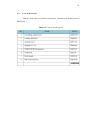
LIST OF TABLES
TABLE NO.
TITLE
PAGE
3.1
Measurement for Feeding Part
41
4.1
Result for the Soup to Complete Cooked
51
4.2
Cost of overall project
52
ix
LIST OF FIGURES
FIGURE NO.
TITLE
PAGE
1.1
Gantt chart for Final Year Project (FYP) 1
3
1.2
Gantt chart for Final Year Project (FYP) 2
4
2.1
Automatic Doughnut Cooking Machine
6
2.2
Overall system for the machine
9
2.3
The location of burner
10
2.4
Overall machine preview
11
2.5
Overall preview of Chinese automatic
13
cooking machine
2.6
Wok mechanism
13
2.7
Stirring and dispersing mechanism
14
2.8
Feeding mechanism
14
2.9
Automatic barbeque cooking machine
16
2.10
Movable runner and speed gear motor
17
2.11
French fry automatic cooking machine
18
2.12
Overall preview of fried potato
20
2.13
Basic design of automatic cooking machine
for boiled noodles
22
3.1
ABS material
26
3.2
Project block diagram
26
3.3
Arrangements of the cooking system
27
3.4
Flow chart of the system
28
3.5
Feeding compartment
29
3.6
3D printer
30
x
3.7
Stepper motor
31
3.8
Motor driver
31
3.9
PIC16F876A circuit board
32
3.10
Arduino Uno board
33
3.11
12V 10A relay
34
3.12
Schematic for the relay
35
3.13
Relay connection
35
3.14
Circuit design for relay
36
3.15
12V DC motor pump
37
3.16
H-bridge L293DNE
37
3.17
Schematic for L293DNE
38
3.18
L293DNE connection
39
3.19
12V 2A AC adapter
40
3.20
Power supply distribution
40
3.21
Overview of SolidWorks 2010 software
41
3.22
MicroC compiler MPLAD IDE
42
3.23
Code to control the rotation of stepper motor
43
3.24
Arduino compiler interface
44
3.25
Connection of Arduino Uno board
45
3.26
Timing for cooking component
46
4.1
Feeding compartment installation
48
4.2
Full set-up of the cooking system
49
4.3
Cooking pot
50
4.4
Final output of the automatic cooking
51
machine
xi
LIST OF SYMBOLS AND ABBREVIATIONS
DC
-
Direct Current
V
-
Voltage
A
-
Ampere
W
-
Watt
mm
-
Millimeter
xii
LIST OF APPENDICES
APPENDIX
TITLE
PAGE
A
Source Code for PIC
56
B
Source Code for Arduino
63
C
Stepper Motor Datasheet
65
D
PIC16F876A Datasheet
66
E
Relay Data Sheet
67
CHAPTER 1
INTRODUCTION
This chapter describes the background of the project, the problem statement of
the project, objectives of the overall project and scope which are related to the
development of an automatic cooking machine.
1.1
Background of Project
Nowadays, it is hard to get fresh and healthy food at food outlets. Eating out
sometimes require us to survey about the cleanness and the cost of the dish that we
are ordering. So cooking at home is more preferable than eating out. We can be sure
that what we are eating is clean and contains enough nutrition than eating or just
buying ready-made food outlets
Cooking at home need some steps starting from gettiing the raw ingredients,
cooking, serving and end with the cleaning of the cooking equipment. To make all
this steps easier, an automatic cooking is designed to help human in preparing their
dish with the combination of all cooking process in a system. The available cooking
machine nowadays is mostly for commercial use, more complex, big in size and also
2
sold at the highly cost. Hence, automatic cooking machine from this project is
designed for home application with simpler, smaller and also at reasonable price.
This automatic cooking machine will be able to serve simple Asian dishes such as
soup-based dishes.
1.1
Problem Statement
Cooking requires a lot of time spent in the kitchen which sometimes make us
tired. The condition is almost true, especially for working mothers and those who
strongly think that fresh food prepared at home are more nutritious with less artificial
additives added to it. However, time may just be the problem. Once a person focuses
on her/his cooking he/she will feel tired to continue other housework. Due to these
conditions, a home automatic cooking machine is proposed to overcome this
problem. The cooking process will be done with just the press a button which saves a
lot of time and energy.
1.2
Objectives
The main objective of this project is to design a home automatic cooking
machine that is able to prepare basic Asian dishes with just the press of a single
button. The proposed automatic cooking machine combines several basic cooking
equipments which includes a cooking induction and feeding mechanism. The timing
for each cooking sequence will be organized by a microcontroller.
3
1.3
Scope of Project
This project is divided into 2 main parts that involves the hardware and
software part. The hardware consists of a cooking induction, feeding mechanism,
stepper motor, and peristaltic pump. The software part is used to control and design
the hardware part. SolidWorks is used to design the feeding part and Arduino and
MicroC compiler MPLAD IDE to control the stepper motor and timing of each
component in cooking process.
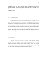
1.4
Summary of Work
Figure 1.1 and Figure 1.2 show the summary of work for the overall project
Figure 1.1: Gantt chart for Final Year Project (FYP) 1
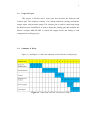
4
Figure 1.2: Gantt chart for Final Year Project (FYP) 2
1.5
Thesis Organization
The first chapter introduces the project in brief. This chapter describes the
background of the project, the problem statement, objectives and the scope of the
overall project which are related to the development of an automatic cooking
machine.
The second chapter discusses on the research of previous researches that are
related to the concept of automatic cooking machine. The literature review focuses
on the types of food, types of food storage, and also the flow of cooking method that
were used in work done in previous projects and researches.
Chapter 3 explains on the step by step methodology of the project which
involves the programming of the PIC16F876A microcontroller using Microchips
software to control the stepper motor and it‟s driver, designing the feeding
mechanism using SolidWorks, and also controlling all the cooking steps using
Arduino Uno board.
5
The results obtained from the project are presented in Chapter 4 with some
discussion on the results. Lastly, Chapter 5 concludes the overall project with some
recommendations for future developments of the current prototype.
CHAPTER 2
THEORY AND LITERATURE REVIEW
This chapter summarizes the researches that has be done from the related
fields of the project which involves the study of various type of automatic cooking
machine and the overall working system and the cooking components that involved
of the related projects.
2.1
Introduction
The automatic cooking machine is the machine that helps human in cooking
activities. All the cooking process is controlled by the special microcontroller. An
automatic cooking machine usually designed by the combination of several cooking
modules such as heating, feeding, stirring, control system, cleaning and fire control
module. This entire module is centered into a station and working in the same place.
The design of automatic cooking machine is different and based on what type of food
produced. Based on the research on several cooking machine, the application of this
machine can be divided into different types of food such as pastry maker, Asian
dishes, Western dishes and automatic vending machine.
7
2.2
Pastry Maker
Pastry is one of the dishes that are made from flour as the main ingredients.
This type of dish can serve itself using an automatic cooking machine. Special
automatic cooking machine was built to serve a doughnut as the output. All the
process to make a doughnut is placed inside this machine.
2.2.1
Automatic Doughnut Cooking Machine
This machine was built to produce a doughnut with all the processes were
conducted by a machine and designed by Louis Snyder [1]. This is one of the first an
automatic cooking machine that was presented. Figure 2.1 shows the diagram of this
cooking machine.
Figure 2.1: Automatic Doughnut Cooking Machine
8
The dough that already made to make a doughnut was sent to the specific
container where the dough is stored and ready to use. The dough then compressed
and cut into needed amount. This process will take place in cutter vessel. After that
the dough will sent into the hot grease for cooking process.
The doughnut then placed on basket and travel under the wires until the
doughnut is cooked. After the doughnut is cooked, then it is ejected to the chute or
incline tray. These machines use a lot of motor to compress the dough and also to
rotate the doughnut in cooking process. After the doughnut already cooked is
automatically removed from the machine and ready to serve to customer.
In this machine there are several cooking components involved that are
storage compartment, cutter vessel, hot grease and incline tray. Storage compartment
is use to store the dough before it was sent for cooking process. Cutter vessel is
located inside this machine to cut the needed amount of dough. The function of hot
grease is where the doughnut is cooked and incline tray is used to place the cooked
doughnut and sent to the user of this machine.
2.3
Asian Dishes
In designing an automatic cooking machine, Asian dish become one of the
famous choice for the developer as the output dish for their machine. The steps in
making Asian dish such as Chinese food is very complex and require a lot of time if
serve it manually. Some of the automatic cooking machines are built to overcome
this problem.
9
2.3.1
Automatic Machine For Cooking Sour-Paste, Rice, Pot Herbs Or Other
Food-Stuff In Water
This automatic cooking machine is designed for cooking process that
involved the use of water to cook it [2]. The main components of this machine are
the burner, temperature control and timing process. This machine also use a lot of
conventional control board with programming circuit to operate each mechanical
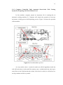
movement. Figure 2.2 shows the overall system of this machine.
Figure 2.2: Overall system for the machine
The process begin when the tank is filled with hot water through articulated
assembly. The level of water is controlled by switch that control the opening of valve
that control the amount of water to be load inside the tank. Below the basket burner
is located for next cooking process. One or more burner is needed to heat the basket
than contained food that want to cook to make sure heating process work perfectly.
Figure 2.3 shows the location of burner.
10
Figure 2.3: The location of burner.
To avoid any problems regarding heating process or burner process,
conventional thermocouples and warning lamps are provided inside this machine that
controlled with valve. To convey smoke and combustion products that are produce
during heating process, special container was designed on top of the tank that called
chimney. So the smoke will release to surrounding with safely.
The food inside the basket will remain inside the basket and deep into the
tank that contain a hot water until it perfectly cooked. Timer control is provided to
control the accurate time for the certain types of food to be cooked. After the food is
cooked, basket is lift up from the tank and move from K1 to K2 (refer Figure 2.2). At
the same time the burner controller will stop the heating process. The contents inside
the basket will place into a hopper that located above the basin and ready to pick.
The process will start from the beginning from the first step after all the food inside
the basket is already placed into the basin.
The burner play an important part in this automatic cooking machine as
cooking module. Valve is used to control the amount of water inside the tank. The
timer is set to different type of food to check weather the food is already cook or not.
This machine used chimney to control the amount of smoke that are produced during
the burning process to the surrounding.
11
2.3.2
Computer Controlled, Fully Automatic Short-Order Wok Cooking
System For Preparing Stir-Fried Chinese Food
In this machine, computer played an important role in running this an
automatic cooking machine [3]. Computer will control the operation of conveyer
movement, cooking process and dispensing process. Figure 2.4 shows the operation
of this machine
Figure 2.4: Overall machine preview
At every station, stirrer is placed to make sure all the ingredients inside the
wok will cook nicely. At the end of the station, sauce is added inside the wok to give
some flavor to the food that already cooked. After food is cooked, it will deliver to a
serving container at delivery station.
12
Next the wok will enter the cleaning station where all the raw material that
remains inside the wok will clean and ready to use in next cooking process. At this
moment, the wok will be inverted. Hot water and soap are ejected into the wok
through small pipes. Air steam and clean water is blasted to dry the wok and now the
wok is ready to enter the cooking stations
The machine is divided into several stations. Conveyer is used to bring the
wok into the different station. Three feeding mechanism is placed on top of the
conveyer that contain three different ingredients. Stirrer also placed during the
cooking process to stir the ingredients inside the wok. Additional feeding part also
uses to pour sauce into the dish. This machine is almost complete when it contains
the cleaning station inside the machine that will clean the used wok and start the new
cooking process.
2.3.3
A New Automatic Cooking Machine for Chinese Dishes
This machine is designed to serve the Chinese food with the basic of Chinese
cooking technics [4]. The idea came from the difficulties to serve Chinese food. It is
take a lot of time to finish every single dish. So this automatic cooking machine will
doing all cooking process automatically and can save a lot of time and energy. Figure
2.5 shows how this machine looks like.
13
Figure 2.5: Overall preview of Chinese automatic cooking machine
At the wok mechanism, the wok will move and shaking a little bit at it
starting position. This happened to ensure heat will separated evenly to the ingredient
inside this wok. This mechanism works together with dispersing mechanism. Figure
2.6 shows the principle of wok mechanism.
Figure 2.6: Wok mechanism
Stirring and dispersing mechanism is important in cooking process to make
sure that food that we cook is not over cooked. Stirring also important to make sure
the sticky ingredients heated thoroughly and also to prevent some ingredients stick
inside the wok after finishing cooking process. Figure 2.7 shows the cover
mechanism that used in this automatic cooking machine.
14
Figure 2.7: Stirring and dispersing mechanism
Next, the most important mechanism is feeding mechanism that decided how
the ingredients are inserted into the wok. For this automatic cooking machine the
ingredients are packed into corresponding cooking menu or dish. The ingredients are
sorted according it is priority to be put inside the wok. Figure 2.8 shows all the
ingredients are sealed with film and placed on the conveyer.
Figure 2.8: Feeding mechanism
The conveyer will rotate clockwise direction. Force F1 and F2 will rotate the
elasctic axis in clockwise and the film the covered the ingredients will tear out an the
ingredients will drop into the wok one by one. The timing is set by the
microcontroller.
15
The mechanism of leaving the material in the middle process is important in
serving the Chinese food. This mechanism will works together with wok mechanism.
Some of the ingredients need to fry first so this mechanism needs move up and down
and turn over process to achiece this mechanism.
For the control system for this machine it uses micro-processor MC56F8322
that will control all the cooking process inside this machine. The C++ programming
language calling OpenGL API library functions is used to design the control system
for this machine. For the fire control unit to prevent any unwanted accident during
cooking process, CO concentration sensors are used for safety monitoring.
In this machine, cooking step is divided into five mains part that is wok
movement mechanism, stirrer, feeding mechanism, mechanism of leaving the
material out in the middle cooking process and fire control system. For the feeding
part, the conveyer was use to bring all the ingredients into the wok. This machine
also has a timing that controlled by microcontroller to control the all the cooking
process.
2.4
Western Dishes
Beside Asian dishes, an automatic cooking machine for Western dish also
presented by the designer. Western dish mostly use oil as the main medium to serve
this type of dishes. French fry and barbeque are the several types of Western dish
that implemented in an automatic cooking machine.
16
2.4.1
Automatic Food Cooking Machine for Barbeque
This automatic cooking machine is based on heating process and look like an
oven to cook a food such as barbeque [5]. The main components of this machine are
heating part and also the conveyer that will rotate the food inside this machine.
Figure 2.9 shows the overall part of this machine.
Figure 2.9: Automatic barbeque cooking machine
This machine is made of metal that will help in heating process but the
outside is covered with insulator to reduce heat transfer to outer of this machine.
From the Figure 2.9, we can see this machine use conveyer as a medium to rotate the
food inside this machine. A pair of parallel shafts inside this machine work as gear to
operate the conveyer. The shaft is connected to speed gear motor.
Along this conveyer, flat basket that is connected at the conveyer chains with
rods and a pair of lug. The size of basket is depending of the size of food that wants
to cook inside this machine. The foods enter from door and place on the parallel
basket then pass through the heating elements and oven.
17
The conveyer will rotate in clockwise direction. At the bottom left of this
machine there is located sauce tank to give some flavor of the food. During the cycle
of conveyer, food will be dip into the sauce tank and drip the excess sauces when the
basket in vertical position. This process continuous until the food is cooked.
Figure 2.10: Movable runner and speed gear motor
When the food is already cooked, a pair of movable runners will put
outwardly from the oven and over the sauce tank to collect the cooked food. After
finish new uncooked food can be placed inside this machine by pushed back the
movable runners to the center of the oven. Figure 2.10 shows the movable runner and
speed gear motor.
In this machine, the feeding part is consist of conveyer that rotated by the
speed gear motor. The ingredients is placed on the conveyer and sent to difference
cooking station. Oven is used and placed inside this machine that function as cooking
element.
18
2.4.2
A New French Fry Automatic Cooking Machine
This machine is improved of the previous french fry automatic cooking
machine. This machine use cooking oil to fry the french fry [6]. Cooking oil is placed
inside the cooking basket. All mechanical movements are controlled by
microprocessor unit. Figure 2.11 shows the system of this machine.
Figure 2.11: French Fry Automatic Cooking Machine
The process begins when container that contains french fry is pushed inside
the machine through access window. The container then stayed at container
receptacle. Then the container receptacle will rotate about receptacle rod. This
process is important to make sure food inside the container will cook wisely inside
the cooking basket that contains the cooking oil. After certain time, microcontroller
decide that food is already cooked and lift up and rotated about basket rod to rinse
the excess oil inside the food. Then the cooked food will placed inside its original
place and ready to serve.
19
This machine is divided into several parts and system:
•
The Flushing Cycle ( inside microcontroller)
For this part, flushing timer is used inside microcontroller. This timer will control the
on/off of the machine, time for heating process and control when the draining
process should be start.
•
Air Filtration System
Exhaust fan that located on top of the machine is used to suck air or heat inside the
machine and sent out to surrounding during cooking process. The air is filtered first
by three activated-charcoal filters before it sent to surrounding. So, smelly odor from
cooking process will filter out.
•
The Dumping Mechanism
Where the container that contains food is sent to container receptacle and it will
deep the food into hot cooking oil.
•
Fire Extinguisher Operation
It‟s made of glass bulb that will detect the temperature greater than 2120 F.
The liquid inside this bulb will explode and discharge the fire extinguisher.
Microprocessor will detect the change of fire extinguisher and it will shut down all
the operation inside this cooking machine.
The feeding part is the main part of this project. The rotation of the container
along the rod is controlled by microprocessor wheater the french fry is cooked or not.
Specific motor is used to do the rotation process. The technique is used to cook the
fries is by deeping the container inside the cooking oil. Fire extinguisher operation
also build up inside this machine to control the any accident during the cooking
process.
20
2.5
Vending for Automatic Cooking Machine
Some of the automatic cooking machine are designed with the vending
machine for commersial use. The design of this types of cooking machine is more
complex and bigger in size.
2.5.1
Automatic Machine For Vending Fried Food
This machine was designed by Frederic A. Sicher and friends [7]. This
machine is works with the combination of vending machine that will decide whether
the machine can operate or not. The output of this machine is to serve the batch of
fried potatoes. Figure 2.12 shows the overal preview of this machine.
Figure 2.12: Overall preview of fried potato
21
Electrical operating and control circuitry were used to control the vending
machine and all the mechanical systems. Timing and drive motor were used also in
cooking process where the potato is deep into the cooking oil.
The machine contains of removable and replacement tray that contains the 49
rectangular bins batch of potatoes. The process begins when the one of the bin is
opened. The opening of bin was controlled by release door and pivot shaft. Then the
batch of potatoes will drop into potato‟s channel and go inside the wire basket. The
wire basket will operate with another container look like a bowl that transmits the
batch of potatoes into the cooking oil for frying process.
The movement of bowl is controlled by piston that connected with piston
forming rod. This rod will move up and down by an operating motor. After batch of
potatoes is already cooked, the motor will lift the rod up into the wire basket and sent
to the chute leading to a compartment. The potatoes then will put inside the tray and
ready to pick up by customer
This machine is contains of removable and replacement tray, wire basket,
piston, frying station and chute. Removable and replacement tray are working as
food storage to store uncooked the batch of potatoes. The wire basket and piston are
work as the feeding part before it was sent to frying station. The chute is used to dry
out the oil and sent the batch of fried potatoes to the user.
2.5.2
Automatic Cooking Machine for Boiled Noodles
The machine was built for boiled noodles in Japan and designed by Tatsui
Tsunoda and friends [8]. This machine is built with the vending machine.
22
The basic component of this machine is divided into two parts, refrigeration
chamber and cooking chamber. Refrigeration chamber is where the bunch of noodles
was stored before sent to cooking chamber for cooking boiling process.
The bunch of noodles in the container was placed between two adjacent
radial blades. The rotary shaft will rotate the drum. The rotation of drum was
controlled by stepper motor below the drum. The container will placed on by one
into cooking table when motor is rotated. Between the refrigeration chamber and
cooking chamber, the inclined guide chamber was placed as transfer medium for the
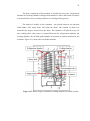
container. Figure 2.13 shows the overall this machine.
Figure 2.13: Basic design of automatic cooking machine for boiled noodles
23
The bunch of noodles in the container was placed between two adjacent
radial blades. The rotary shaft will rotate the drum. The rotation of drum was
controlled by stepper motor below the drum. The container will place on by one into
cooking table when motor is rotated. Between the refrigeration chamber and cooking
chamber, the inclined guide member was placed as transfer medium for the
container.
After the container placed on the cooking table, the boiling noodles will start.
A hot water tank which is provided with heater will supply the hot water into the
container. It is placed directly above the cooking table. The amount of hot water that
will use to boil the noodle was controlled by conventional timer.
Then the cooking table is rotated about its position to drain the hot water out
of container to reservoir. After draining process, concentrated broth inside the broth
tank is poured into the container through supply pipe. The supply pipe was provided
with conventional electromagnetic valve and broth is mixed with the new hot water
supply.
This machine consists of refrigeration and cooking chamber. The feeding part
of this machine is consist of bunch of noodles in the container, rotary shaft, stepper
motor and electromagnetic valve. Stepper motor is used to control step by step of
food container into the cooking chamber while the electromagnetic valve control the
flow of broth into container. To cook the noodles, heater is used as cooking
components to heat the water for boiling the noodles inside the cointainer.
Conventional timer is used to set the time require for noodle to cook before it sent to
the user.
24
2.6
Advantages and Disadvantages
Based on the research of previous researches, most of the automatic cooking
machines are complex and only suitable for commercial or industry use. Although all
of these automatic cooking machines are complete in cooking equipments but the
size will become the problem for the user to store or placed in their house. So, this
problem will lead in designing a new automatic cooking machine that is simpler and
affordable in price. The most important part in an automatic cooking machine is the
cooking and feeding module. Both these module can be implemented in this project
to make it simpler. This proposes design also suitable for home application and will
reduce the time and energy of the user.
CHAPTER 3
RESEARCH METHODOLOGY
This chapter discusses about the overall project implementations and how it is
done throughout two semesters. It consists of five parts, which includes the general
construction, project overview, hardware design, electrical design and software
development.
3.1
Basic Construction
To design an automatic cooking machine, several cooking process should be
used. For this project heating and feeding elements are used to cook certain food.
Cooking induction is used as heating elements while the stepper motor is used to
control the feeding part. All the cooking elements are placed at retort stand that work
as a holder for the cooking elements. In this project, soup-based dishes are preferred
to complete the cooking process by just press a button. Acrylonitrile butadiene
styrene (ABS) is a material used for feeding part that designed to store the cooking
ingredients before it drop into the cooking pot. Figure 3.1 shows the example of ABS
material
26
Figure 3.1 ABS material
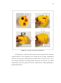
3.2
Project Overview
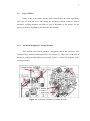
Figure 3.2 Project block diagram
Figure 3.2 shows the basic block diagram of the overall system of this
project. The ingredients are placed first in the feeding compartment before the switch
is ON. The project comes along with the toggle switch that works as switch that
control all the operation of the system. When toggle switch is on, the microcontroller
will ON and starts operates and decide which cooking process needs to start first.
27
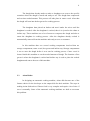
To control the feeding part, stepper motor is use an attached on top of the
feeding compartment. The motor will rotate the cylinder inside feeding compartment
and the ingredients will drop one by one into the cooking pot. The cooking pot is
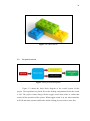
placed on the cooking induction below the feeding compartment. Figure 3.3 shows
the arrangement of the overall system.
Figure 3.3 Arrangements of the cooking system
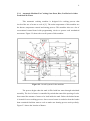
All the cooking process is controlled by the microcontroller after the switch is
ON. The main important part for this project is the timing and delay of every cooking
element to start it work. Figure 3.4 shows the flow chart of this project.
28
START
ON the main power supply
ON the power button
Heat pot on cooking induction
2 minutes
Pour water from motor pump into the pot
1 minute
Turn ON feeding mechanism
Drop ingredients into pot
Leave the ingredients inside the pot
2 minutes
OFF cooking induction
END
Figure 3.4: Flow chart of the system
3.3
Hardware Design
Hardware part is one of the most important parts in designing and automatic
cooking machine. For this project, feeding part is needed to be designed. The design
process is done by using SolidWorks2010 software [9]. It categorizes into three main
29
parts that is cylinder, cap, and motor external. Figure 3.3.1 shows the all three
designs.
Cylinder
Cap
Motor External
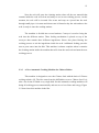
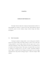
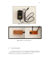
Figure 3.5: Feeding compartment
Cylinder is works as place to store the ingredients before it will drop into the
cooking pot. Cap plays as a holder for the cylinder. After the ingredients is placed
inside the cylinder then it will cover by the cap before inverted while the motor
external is connected to the stepper motor and placed on top of the cylinder. Both
cylinder and stepper motor are hold with clamp along the retort stand to make the
cylinder will rotate smoothly during dropping the ingredients inside the cooking pot.
The 3D printer is used to print out all of this design. Figure 3.6 shows the 3D
printer that was used.
30
Figure 3.6: 3D Printer
3.4
Electrical Design
The electrical design and circuit connection need to modify to make sure all
this cooking component will work automatically just by press a button. There are
five main parts which includes stepper motor, microcontroller design, switching
relay, motor pump, and power supply.
3.4.1
Stepper Motor
Stepper motor [10] is used to control the rotation of feeding compartment.
Figure 3.7 shows the stepper motor used. To control the rotation of motor, first things
we used motor driver to generate the motor and can easily control the type of
movement. Figure 3.8 shows the motor driver used. For this project we just created
four segments at the cylinder where three is used as ingredients storage and another
31
segment is reserved for initial state of rotation to block the ingredient from flow out
through the cap.
Figure 3.7: Stepper motor
Figure 3.8: Motor driver
To control the rotation the stepper motor we use PIC16F876A [11] and ready
made from Cytron Technologies. Some adjustment needs to be done so it follows the
scope of this project. All the compartment need to solder to the board based on
schematic given. Figure 3.9 shows the PIC16F876A before and after solder process.
32
Figure 3.9: PIC16F876A circuit board
3.4.2
Microcontroller Design
Microcontroller is the main of the system. For this project we used
PIC16F876A to control the stepper motor and Atmega328 that located in Arduino
Uno board that will control the operation of every cooking components and the
timing for each of them. The Arduino Uno board will sent the output high to every
component to ON them. For this project we just used 4 output ports (Digital I/O
Pins) to control the cooking induction, feeding compartment, motor pump and
indicator. For this project LED is representative as the indicator. Figure 3.10 show
the Arduino Uno board that was used in this project.
33
Figure 3.10: Arduino Uno board
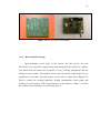
3.4.3
Switching Relay
Relay is electronic components that will work as switch to control the current
flow by using the electromechanical concept inside it. For this project, relay is used
to control the ON/OFF of the cooking induction. Relay is choose based on load that
it can supported. Our cooking induction is operating on 220-240V and 1500W. So
12V 10A relay [12] is choose because it can support the power 1500W. Figure 3.11
shows the relay used.
34
Figure 3.11: 12V 10A relay
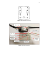
Relay usually comes in with two types of mode of operation that is normally
closed and normally opens. For this project we connected this relay to normally open
pin so that the relay will work as switch when we sent output high from the Arduino.
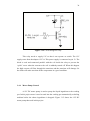
Figure 3.12 shows the circuit diagram for the relay we used. So to connect this relay
with cooking induction the live wire from the cooking induction need to cut into 2
parts.
One is connected to pin 1 and another to pin 9. So when the power is ON the
relay will work as normally open. Figure 3.13 shows how the relay is connected to
cooking induction. To ON the relay we also need to design simple circuit so that it
will turn on when output high from Arduino Uno board is sent to the relay. Figure
3.14 show the circuit that need to design for the relay. Transistor and resistor is used
for the designation.
35
Figure 3.12: Schematic for the relay
Figure 3.13: Relay connection
36
Figure 3.14: Circuit design for relay
This relay needs to supply 12V so that it can operate as switch. The 12V
supply came from the adapter 12V 2A. This power supply is connected to pin 13. The
diode is used and connected parallel with the coil inside the relay to prevent the
“spike” occur when the current to the coil is suddenly turned off. When this happen
the high current will flow through the transistor and the transistor will damage. So
the diode will make sure that all the components in a good condition.
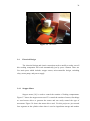
3.4.4
Motor Pump Control
A 12V DC motor pump is used to pump the liquid ingredient to the cooking
pot. In this project water is need to send into the cooking pot automatically as boiling
medium before the others ingredients is dropped. Figure 3.15 shows the 12V DC
motor pump that used in this project.
37
Figure 3.15: 12V DC motor pump
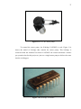
To control the motor pump, the H-bridge L293DNE is used. Figure 3.16
shows the model of h-bridge that controls the motor pump. This h-bridge is
connected with the Arduino Uno board. L293DNE can control maximum 2 motors
per operation but for this project we just use a single motor pump to deliver the water
into the cooking pot.
Figure 3.16: H-bridge L293DNE
38
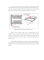
Figure 3.17 shows the schematic of H-bridge L293DNE and how it is
connected with the Arduino Uno board.
Figure 3.17: Schematic for L293DNE
Pin 3 and 4 is connected to motor pump while pin 8 and pin 16 are connected
to 12V power supply and 5V Arduino Uno board voltage supply respectively. All the
connection is connected on protoboard. Figure 3.18 shows the connection of
L293DNE and Arduino Uno board. H-bride can control the direction of DC motor,
but for this project we just prefer one direction only to send the water into the
cooking pot.
39
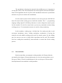
Figure 3.18: L293DNE connection
3.4.5
Power Supply
In this project, two different power supplies are used. 240V for the cooking
induction while 12V 2A for Arduino Uno board, PIC16F876A and relay supply.
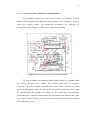
Figure 3.19 show the 12V 2A adapter. To make this system more automatically and
to reduce the power supply source new circuit needs to design. Simple circuit is drew
on board and go for etching process. Figure 3.20 show how 12V 2A is distributed to
the microcontroller and the relay.
40
Figure 3.19: 12V 2A AC adapter
Figure 3.20: Power supply distribution
3.5
Software Development
In this project software part is one of the main part in designing an automatic
cooking machine. The software we used is SolidWorks 2012, MicroC for the PIC
and Arduino in constructing the design and algorithm of the project.
41
3.5.1
SolidWorks 2010
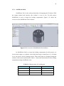
SolidWorks 2010 is the software that helps in designing the 3D object. With
the simple manual and interface this software is easy to use. For this project
SolidWorks is used to design the feeding compartment. Figure 3.21 shows the
overview of the SolidWorks 2010 software
Figure 3.21: Overview of SolidWorks 2010 software
In SolidWorks 2010, to create the feeding compartment for this project, we
just use basic shape as a cylinder. After finish the design, it should save in .stl format
so we can send it for the printing process. Three main parts are designed using this
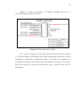
software with certain measurement. Table 3.1 shows the measurement of the feeding
compartment using SolidWorks 2010.
Table 3.1: Measurement for feeding part
PART
DIAMETER (mm)
HEIGHT (mm)
Cylinder
50
80
Cap
51
85
-
40
Motor external
42
3.5.2
MicroC for Peripheral Interface Controller (PIC)
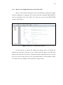
MicroC is the software that used to write and compile the program for stepper
motor in feeding part. C language [13] is used to write the command. MPLAB IDE is
used as a platform for the code. Figure 3.22 shows the overview the MPLAB IDE
software from MicroC.
Figure 3.22: MicroC compiler MPLAD IDE
For this project, to control the rotation the stepper motor we divided the
rotation into four steps. Each step is set to rotate about 900 degrees and add some
delay for the next turn. The delay is obtained from the experiment on types of food
we use to cook. For this project we use soup-based dishes as a food sample. Figure
3.23 shows how the coding to set the rotation of stepper motor.
43
Figure 3.23: Code to control the rotation of stepper motor
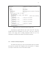
After finish the compiler than the code is burn into the PIC chip using
UIC00B USB ICSP PIC Programmer [14]. The PIC is used just to control the
rotation of the stepper motor in feeding compartment while the rest of the
components are controlled by the Arduino Uno board microcontroller.
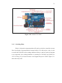
3.5.3
Arduino Uno Board (Atmega328)
The Arduino Uno board [15] is types of microcontroller that easy to handle
and compile the command. Basic language for this microcontroller is C language
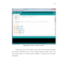
[13]. Figure 3.24 shows the overview of the Arduino compiler.
44
Figure 3.24: Arduino compiler interface
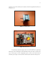
In this project the use of Arduino is more focus on the timing and switching
the electrical components such as relay (cooking induction), stepper motor, and
motor pump. Figure 3.25 shows how the Arduino is connected to the electrical
components.
45
Figure 3.25: Connection of Arduino Uno board
The LED in the circuit represents the indicator in this project. The green LED
will light when the switch is ON. The red LED will light up and connected to the
relay at the cooking induction while the yellow LED is for feeding part. When the
yellow LED light up then stepper motor will start to rotate. The ON/OFF the LED
shows the current operation cooking components.
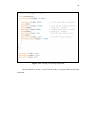
The timing to ON/OFF the cooking components is decided based on the
experiment how the components should ON or OFF to finish a complete dish. Figure
3.26 shows the coding for Arduino to set the timer for each of the cooking
components.
46
Figure 3.26: Timing for cooking component
In the Arduino to set the 1 second for the delay we just put 1000 on the delay
command.
CHAPTER 4
RESULTS AND DISCUSSION
This chapter discusses on the results obtained from the experiments and
solutions on problems faced during the progression of this project.
4.1
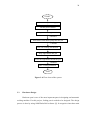
Feeding Mechanism
The feeding mechanism in this project is designed to be a rotating type.
Figure 4.1 shows the installation of the feeding cylinder. The cylinder has 3
compartments to store the cooking ingredients. It is fixed to a „cap‟, which is a
hollow cylinder, with one of its end closed. The closed end has a hole to allow the
cooking ingredients to drop. The stepper motor is connected at the top of the cylinder
where special square hole is built.
48
Figure 4.1: Feeding compartment installation
In this project, a soup-based dish is used to test the operation of the automatic
cooking machine. Three ingredients were loaded into the feeding compartments
which are the soup paste, minced chicken and fried onion. The hole on the „cap‟ is
set to meet the flat surface of feeding cylinder. The motor will rotate the „cap‟, which
automatically rotates the position of the hole, which allows cooking ingredients to
drop through the hole.
49
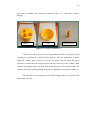
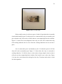
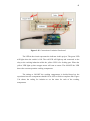
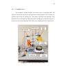
4.2
Cooking Process
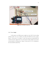
The automatic cooking machine was tested using a soup-based dish. The
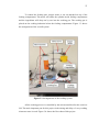
Figure 4.2 shows the full set-up of the automatic cooking machine. The first step is to
boil the water inside the cooking pot. Time taken to boil the water depends on the
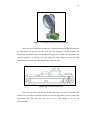
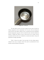
thickness of the cooking pot. In this project thin cooking pot (as shown in Figure 4.3)
was used to save the boiling time. And reduce the waiting time for the soup to cook.
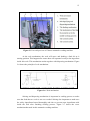
Figure 4.2: Full set-up of the cooking system
50
Figure 4.3: Cooking pot
The time taken for water to boil was recorded. Once the water is boiled, the
feeding compartment will be automatically ON. The motor will start rotating and
causes the hole on the hollow cylinder to move its position to the first compartment
and start dropping the soup paste. After 30 seconds, the motor will rotate and minced
chicken is dropped and follow by the fry onion after next 30 seconds. Several
experiments and observation were conducted to record the time taken to drop each
ingredients of feeding compartment
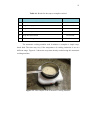
Table 4.1 shows the results of the time taken for each cooking sequence
obtained for the soup to complete cooked. The result is recorded based on time
needed to start the operation of each process.
51
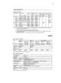
Table 4.1: Result for the soup to complete cooked
NO
COOKING PROCESS
TIME
1
Pre-heat water until its boiled
2 minutes
2
Drop the soup pastes
30 seconds
3
Drop the minced chicken
30 seconds
4
Wait the soup to cook
30 seconds
5
Drop the fried onions
10 seconds
6
Off the cooking induction
After 3 minutes
The automatic cooking machine took 4 minutes to complete a simple soupbased dish. The time may vary if the temperature of cooking induction is set at a
different range. Figure 4.3 shows the soup that already cooked using this automatic
cooking machine.
Figure 4.3: Final Output of the Automatic Cooking Machine
52
4.3
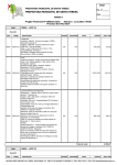
Cost of the Project
Table 4.2 shows the cost of the overall project. The total cost of this project is
RM550.00
Table 4.2: Cost of overall project
CHAPTER 5
CONCLUSION AND RECOMMENDATIONS
This chapter concludes the whole project and proposes some improvements
for future advancement to enhance the application of this project
5.1
Conclusion
The development of an automatic cooking machine can be done by
combination of several basic cooking equipments. In this project soup-based dishes
is choose as food sample. Starting with the pre-heat the cooking induction until all
the ingredients are dropped into the cooking pot are controlled by the Arduino Uno
microcontroller.
There are several methods that can be used in feeding part to deliver the
ingredients into the cooking pot such as using a conveyer and just using a stepper
motor. Using a conveyer is more practical than using a motor because it can store or
placed a lot of ingredient on it before its ready to send into the cooking pot. In this
54
project stepper motor is used to reduce the cost and it‟s suitable with the design of
feeding compartment in this automatic cooking machine.
The timing of each components are varies depend on the ingredients used.
Several experiments are done to get the correct timing for the dish to cook. Starting
with the time taken for the water to boil inside the cooking pot, ingredient dropping
and last but not list the time require for the dish to complete cooked.
The overall time taken to complete soup-based dish in this project is about 4
minutes before the user can take out the soup from the cooking pot. In conclusion,
the project is successfully implemented and the objectives of the project are achieved
to design an automatic cooking machine with just press a button.
5.2
Recommendations
To make this project more marketable in the future, some improvement and
adjustment are required on this project. To cook different types of food usually need
a lot of ingredients that need to prepare. So to overcome this problem, the feeding
parts need to justify and increase its size and the number of ingredient‟s
compartment.
Next, to improve the quality of cooking stirrer is need to locate inside the
cooking process so that all the ingredients are perfectly cooked. Mechanical stirrer is
suggested so it can be timing with the microcontroller.
REFERENCES
1.
Snyder, L. (June 10, 1932). Automatic Doughnut Cooking Machine..
2.
Alfio, P. (Sep. 20, 1982). Automatic Machine for Cooking Soup-Paste, Rice,
Pot Herbs or Other Food-Stuffs in Water. Italy, Angelo Po Grandi Impianti
S.P.A.
3.
Mak, S. M. (Jul. 27, 1988). Computer Controlled, Fully Automatic, Shortorder Wok Cooking System for Preparing Stir-fried Chinese Food. United
State of America, Larry B. Harvey.
4.
Yan, W. X., S. J. T. U. Robotics Res. Inst., Et Al. (8-10 Oct. 2006). A New
Automatic Cooking Machine for Chinese Dishes Automation Science and
Engineering, 2006. CASE '06. IEEE International Conference On: 534 – 53
5.
Gongwer, N. G. D. (Jun. 12, 1984). Automatic Food Cooking Machine, Nelgo
Manufacturing Corporation.
6.
Maurice Tate, O. C., Fla; Robert L. Thompson; John H. Wilbur (Feb. 27,
1986). Automatic Cooking Machine. Washington, U1 Group.
7.
Frederic A. Slicher, G. E. J. G., Westchester, both of lll (1972). Automatic
Machine for Vending Fried Foods, Slicher, by said Gaysowski.
8.
Tatsui Tsunoda, S. O., Kazuma Miyamoto, Makoto Matsumoto, Heiji Baba
(Feb. 7, 1975). Automatic Cooking and Vending Machine for Boiled Noodles.
Japan, Kawatetsu Metrological Equipment and Vending Machine Company,
Ltd., Nishinomiya, Japan.
9.
Greg Jankowski, R. D. (2008). SolidWorks for Dummies, Wiley Publishing,
Inc.
10.
Minebea Stepping Motor Data sheet. 2013, Minebea-Matsushita Motor
Corporation.
11.
PIC16F87XA Data Sheet. 2003, Microchip Technology Inc.
56
12.
General-purpose Relay Data Sheet. 2003, Omron Corporation.
13.
Gookin, D. (2004). C For Dummies, 2nd Edition. Canada, Wiley Publishing,
Inc.
14.
UIC00B USB ICSP PIC Programmer User’s Manual. 2011, Cytron
Technologies.
15.
Mcroberts.M (2009). Arduino Starters Kit Manual - A Complete Beginners
Guide to the Arduino, Earthshine Design.
57
APPENDIX A
SOURCE CODE FOR PIC
#include <pic.h>
//
//include header file
configuration
//===========================================================
=//
__CONFIG ( 0x3F32 );
//The configuration bits “0x3F32” is used to make
configure the
//correct setting for this PIC, 0x refers to Hexadecimal whereas
3F32 means:
//• Set the oscillator as high speed (HS – 4MHz to 20MHz crystal)
//
//•
Off the Watchdog Timer
//•
On Power On Timer
//•
Off Brown Out Detect
//•
Disable Low Voltage Program
//•
Off data EEPROM Read Protect
//•
Off Flash Program Write Protection
//•
Off Code Protect
define
//===========================================================
=//
#define sw2
RB2
#define led1
RC0
#define led2
RC1
#define led3
RC2
#define pulse
RC3
58
#define direction
RC4
#define en
RC5
//
function prototype
//==========================================================//
void delay(unsigned long data);
void rotate(void);
//
global variable
//==========================================================//
unsigned char on=0, ccw=0, run=0;
//
main function
//==========================================================//
void main(void)
{
unsigned char turn=0;
TRISA=0b11111111;
//set PORTA as input
TRISB=0b11111111;
//set PORTB as input
TRISC=0B00000000;
//set PORTD as output
PORTC=0;
//clear PORTC
ADCON1=0b00000000;
//set PORTA as analog input, left justified
ADCON0=0b01000001;
//configure AN0 as analog channel
led1 = 0;
led2 = 0;
led3 = 0;
59
while(1)
{
if(!sw2)
{
while(sw2==0)continue;
// wait switch 3 to release
delay(6250);
// wait 50ms to prevent bouncing error at switch
on^=1;
ccw^=1;
run^=1;
//interchange between run and stop for each press
(ccw = on Ex-OR with 1)
led3^=1;
//interchange between on and off for each press
(led3 = led3 Ex-OR with 1)
}
while(sw2)
//loopinng if no button is pressed
{
if(on)
//on = 1
{
en=1;
//set enable
if(ccw)
//ccw = 1
{
direction=1;
//set direction pin on motor
driver(CCW)
if(run)
//run = 1
{
for(int seq = 0; seq < 4; seq++)
{
int multiplier;
for(int count = 0; count < 500; count++)
{rotate();}
//motor start rotating
60
if(seq == 0)
{
multiplier = 30;}
if(seq == 1)
{
multiplier = 30;}
if(seq == 2)
{
multiplier = 10;}
if(seq == 3)
{
multiplier = 2;}
for(;multiplier>0;multiplier--)
{delay(125000);}
}
while(1)
//forever
{}
}
else
{
pulse=0;
//run = 0
}
}
else
//ccw = 0
{
direction=0;
//clear direction pin on motor driver(CW)
if(run)
//run = 1
{
for(int seq = 0; seq < 4; seq++)
{
int multiplier;
61
for(int count = 0; count < 500; count++)
{
rotate();}
//motor start rotating
if(seq == 0)
{
multiplier = 30;}
if(seq == 1)
{
multiplier = 30;}
if(seq == 2)
{
multiplier = 10;}
if(seq == 3)
{
multiplier = 2;}
for(;multiplier>0;multiplier--)
{delay(125000);}
}
while(1)
//forever
{}
}
else
//run = 0
{
pulse=0;
}
}
}
else
//on = 0
{
led1=0;
//LED1 off
led2=0;
//LED2 off
led3=0;
//LED3 off
62
en=0;
ccw=0;
run=0;
}
}
}
}
//=========================FUNCTIONS=======================//
void delay(unsigned long data)
{
for( ;data>0;data-=1);
}
void rotate(void)
{
unsigned char i=0;
ADGO=1;
//set ADGO to activate ADC
while(ADGO==1)continue; //wait process of ADC complete
//--------------------------------------------------------// IF the max speed for motor driver = 20kHz
// and T = 1/f. Tmax = 1/10k = 50us
//
// From simulation, "delay(1);" need 40 instruction cycles
// Period for 1 instruction cycle = 1/(20W/4) = 200ns
// Period for 40 instruction cycles = 200n * 40 = 8us
// So, period for "delay(1);" also = 8us
//
// Now if we want to generate a delay of 20us
// the value that we need to put for "delay(x);" is:
//
//
x = 20us/8us*1 = 6.25 = 6
//----------------------------------------------------------
63
if(ADRESH==0)
// stop
{
pulse=0;
}
else if((255-ADRESH)<=6) // maximum speed ( control by potential meter )
{
i = 6;
//read resultant ADC value from ADRESH
pulse=1;
//set pulse pin on motor driver
delay(i);
//delay time depend to the ADC value
pulse=0;
//clear pulse pin on motor driver
delay(i);
}
else
{
i = 255-ADRESH;
//the higher the value of ADRESH, the faster the steps change.
pulse=1;
//set pulse pin on motor driver
delay(i);
//delay time depend to the ADC value
pulse=0;
//clear pulse pin on motor driver
delay(i);
}
}
64
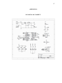
APPENDIX B
SOURCE CODE FOR ARDUINO
int toggle = 2;
// the number of the toggle switch pin
int light = 4;
// the number of the LED pin
int feed = 6;
int cooker = 8;
long bounceDelay = 200;
// increase this if your output is unstable (flickers)
void setup()
{
pinMode(toggle, INPUT);
pinMode(light, OUTPUT);
pinMode(feed, OUTPUT);
pinMode(cooker, OUTPUT);
digitalWrite(toggle, HIGH);
digitalWrite(light, LOW);
digitalWrite(feed, LOW);
digitalWrite(cooker, LOW);
}
void loop()
{
if (digitalRead(toggle) == HIGH )
{
delay(bounceDelay);
if( digitalRead(toggle) == HIGH )
65
{
digitalWrite(light, HIGH);
// on the LED as indicator
delay(1000);
digitalWrite(cooker, HIGH);
// start ON the cooking induction
delay(120000);
// delay for 2 minutes
digitalWrite(feed, HIGH);
// stepper motor start to rotate
delay(60000);
// delay for 1 minutes
digitalWrite(feed, LOW);
// turn OFF the stepper mototr
delay(2000);
digitalWrite(cooker, LOW);
while(digitalRead(toggle) == HIGH)
{
}
}
}
else
{
digitalWrite(light, LOW);
digitalWrite(cooker, LOW);
digitalWrite(feed, LOW);
}
}
// turn OFF cooking induction
66
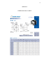
APPENDIX C
STEPPER MOTOR DATASHEET
67
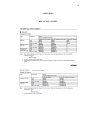
APPENDIX D
PIC16F876A DATASHEET
68
APPENDIX E
RELAY DATA SHEET
69