1
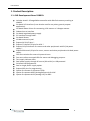
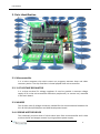
AVR
Development Board
(118010)
User’s Manual
User’s Manual
About the User Guide
AVR Development Board 118010 is especially designed for the students having
interest in electronics, embedded system, robotics and industrial-automation. This board is
made in such a way that it becomes easier for any body to learn about AVR micro
controllers. This board can also be used in various applications and hobby projects.
PROPRIETARY NOTICE
This document contains proprietary information furnished for evaluation purposes only; except with the express written
permission of Technophilia, such information may not be published, disclosed, or used for any other purpose. You
acknowledge and agree that this document and all portions thereof, including, but not limited to, any copyright, trade
secret and other intellectual property rights relating thereto, are and at all times shall remain the sole property
Technophilia and that title and full ownership rights in the information contained herein and all portions thereof are
reserved to and at all times shall remain with Technophilia. You acknowledge and agree that the information contained
herein constitutes a valuable trade secret of Technophilia. You agree to use utmost care in protecting the proprietary and
confidential nature of the information contained herein.
2
User’s Manual
Contents
1. Product Description: ................................................................. 4
1.1. AVR Development Board 118010: ........................................... 4
2. Parts Identification .................................................................... 5
2.1. Microcontroller ...................................................................... 5
2.2. 1117 VOLTAGE REGULATOR ................................................... 5
2.3. MAX232 ................................................................................ 5
2.4. L293DNE MOTOR DRIVER ....................................................... 5
2.5. 16 X 2/16 X 1 LCD INTERFACE ................................................ 6
2.6. SWITCHES .............................................................................. 6
2.7. POWER SUPPLY ....................................................................... 7
2.8. LED’s..................................................................................... 7
2.9. BZ (BUZZER) ........................................................................... 8
2.10. ISP (IN-SYSTEM PROGRAMMING) INTERFACE ........................... 8
2.11. RS – 232 INTERFACE ............................................................. 8
2.12. PB (PORTB) ........................................................................... 8
2.13. PC (PORTC) .......................................................................... 8
2.14. PC (PORTC) .......................................................................... 8
2.15. MOTOR DRIVER CONNECTIONS ............................................. 9
3. The AVR Microcontrollers: ......................................................... 10
3.1. Description ............................................................................ 10
3.2. Programming ......................................................................... 10
3
User’s Manual
1. Product Description:
1.1. AVR Development Board 118010:
Includes Atmel’s ATmega8 Microcontroller with 8kb flash memory working at
16MIPS.
On-board LCD interface (it can also be used for any other general purpose
application).
On-board Motor Driver for connecting 4 DC motors or 2 Stepper motors
Onboard servo interface
On-board regulated power supply.
PC interface through UART.
On-board Buzzer.
12 MHz external crystal.
Exposed all 21 I/O pins.*
Exposed 7 channel I/O pins for ADC *
Exposed 12 I/O channels for sensors and other peripherals with 5V/1A power
supply.*
Exposed 8 channel I/O pins for servo, sensors and other peripherals with dual power
supply.
Four tact switches for external input and reset.
Four test surface mounted LEDs for status and debugging purpose.
Two supply indicator LEDs.
Dual power supply through DC source (6V to 16V) or USB powered.
On board USB programmer.
Dual or single power supply option.
Exposed ISP pins for programming.
Option for connect or disconnect LEDs
Option for separate AREF (Analog Reference) for ADC.
Option for separate AVCC (Analog VCC) for ADC.
4
User’s Manual
2. Parts Identification
2.1. Microcontroller
It is a micro computer chip which stores our programs executes them and takes
necessary action. The chip used here is Atmel popular AVR micro controller.
2.2. 1117 VOLTAGE REGULATOR
It is a three terminal 5V voltage regulator IC used to provide a constant voltage
supply of 5V to the micro controller and other peripherals (i.e. sensors etc.) attached
in the main board.
2.3. MAX232
This IC takes care of voltage conversion needed for the communication between the
PC's RS-232 (Serial/COM) port and AVR Development board.
2.4. L293DNE MOTOR DRIVER
This is basically a motor driver IC which takes input from microcontroller and is able
to drive the DC and stepper motors by using separate power supply.
5
User’s Manual
2.5. 16 X 2/16 X 1 LCD INTERFACE
The LCD interface can be use to interface any 16x2 or 16x1 character LCD display in 4
bit mode. The LCD display can be used to display any message, status or also can be
used for debugging purpose.
The LCD interfacing can also be used as a general purpose input output port. The pin
connections for interfacing an LCD to the board are given below:
D4PortB0
D5PortB1
D6PortB2
D7PortB3
RSPortB4
RW- Ground
EPortB5
XTAL1- PortB6
XTAL2- PortB7
2.6. SWITCHES
Four tact switches along with a Reset switch are present on the board in order to
provide an external input to the board. The switches are connected in the following
manner:
S0 S1 S2 S3 -
PortC0
PortC1
PortC2
PortC3
RST (Reset switch):
The Reset switch is basically used to reset a running program right to the
beginning it is same as the reset switch of a PC.
POWER (Power On Switch):
It is basically a toggle switch used to provide power supply to the main board.
The power can be supplied either by a battery power supply (through LS) or
can be USB powered. Thus, the POWER switch can be made to toggle
between MP (Main Power) or UP (USB Power).
PTOG (Power Toggle Switch):
It is basically a toggle switch which toggles the power for the devices
connected to PORTB either to use the internal power supply (5V) of the main
board (by setting the switch in 5V mode) or to use any other external power
source connected in DS for the high power applications like servo motors (by
setting the switch in EXT mode).
6
User’s Manual
PROG (Programming Switch):
It is also a toggle switch for programming the microcontroller using on board
USB programmer. For programming mode it should be ON then RESET button
should be pressed. For normal operation it should be off.
2.7. POWER SUPPLY
LS (Logic Supply):
It consist of two pins one is +ve and another is –ve. A battery or a AC adaptor
can be connected here to provide power suply to the mother board it
provides regulated power supply to all the peripherials present in the mother
board and also to the external periphrials connected to the motherboard
through a voltage regulator. The DC voltage provided to this terminal should
be lies in between 6 to 16 volt. To use the supply connected in LS pin the
power switch should be toggled towards “MP” (Main power).
DS (Driving Supply):
It consist of two pins one is +ve and another is –ve.It is basically use to
provide a separate high current power supply to the Motors. For operating
DC motors you may provide here a Power supply of 5 to 40 volt. For
operating a servo motor you may suppose to provise any suitable power
supply as per the requirement of your motors (mostly servos works at 4.5 to
6 volt). Power from this pins are directly goes to the driving supply of the
motor driver and to the supply pins of PortB if PTOG switch is toggled
towards EXT.
J1 (Jumper 1):
It is a simple jumper which can be use to use a sinle power supply for DS and
LS. If you put here a jumper then you have to provide supply only on DC or LS
and your board will get both the power supply.
USB socket:
It is basically used for USB communication with the PC. It also provides
necessary logic supply to the motherboard. In order to use the USB supply
the POWER switch should be toggled towards UP (USB power). When using
the USB power some prequtions should be taken such as any heavy load
should not be connected to the board directly and Don’t use the J1.
2.8. LED’s
Active high:
RED LED1 –
RED LED2 –
RED LED3 –
RED LED4 –
ORANGE LS IGREEN DS I-
PORTB0
PORTB1
PORTB2
PORTB3
Logic Power ON indicator
Driver Power ON indicator
7
User’s Manual
2.9. BZ (BUZZER)
It can be easily used to get an audible feedback from the controller. It is connected in
an active high mode, i.e., the buzzer beeps when the data given to it is 1.
The Buzzer is connected to the pin PORTC5 of the microcontroller.
2.10. ISP (IN-SYSTEM PROGRAMMING) INTERFACE
It is the In-System Programming interface of the main board which can be used to
connect any ISP programmer to download the programs in the microcontroller. It
can also be used in SPI (Serial Peripheral Interface) communication. The pins
provided for ISP are given below:
MOSIMISOSCKRSTGND-
Master Out Slave in
Master in Slave out
Serial clock
Reset
Ground
PortB3
PortB4
PortB5
Reset
Ground
2.11. RS – 232 INTERFACE
These is a 3-pin interface that can be used for PC controlled applications, debugging
purpose, data communication with PC and for inter board data communication.
The port consists of three pins, namely,
RReceiver
TTransmitter
GGround.
2.12. PB (PORTB)
It is a general purpose I/O port. This port contains six pins that can be used as digital
input and digital output. These pins are in the form, DATA-VCC-GROUND (denoted as
D + - respectively on the board). The Data pins are towards the microcontroller. The
VCC and Ground pins are provided with a 5V/1A power supply and or the supply to
these pins can also be switched to external supply connected in DS pin through PTOG
switch.
2.13. PC (PORTC)
It is a general purpose I/O port. This port contains six pins that can be used as digital
input, output and ADC. These pins are in the form, DATA-VCC-GROUND (denoted as
D + - respectively on the board). The VCC and Ground pins are provided with a 5V/1A
power supply.
2.14. PC (PORTC)
It is a general purpose I/O port. This port contains eight pins that can be used as
digital input and output.
8
User’s Manual
2.15. MOTOR DRIVER CONNECTIONS
The motor drivers are used to run the DC motors or stepper motors that may be
connected to the board according to the data from the microcontroller. The motor
driver’s link with micro controller is shown bellow.
M0 M1 M2 M3 M4 M5 M6 M7 -
PortB0
PortB1
PortB2
PortB3
PortD4
PortD5
PortD6
PortD7
9
User’s Manual
3. The AVR Microcontrollers:
3.1. Description
The AVR is a Modified Harvard architecture 8-bit RISC single chip microcontroller which was
developed by Atmel in 1996. The AVR was one of the first microcontroller families to use onchip flash memory for program storage, as opposed to One-Time Programmable ROM,
EPROM, or EEPROM used by other microcontrollers at the time.
Atmel's low power, high performance AVR microcontrollers handle demanding 8 and 16-bit
applications. With a single cycle instruction RISC CPU, innovative Pico Power® technology,
and a rich feature set, the AVR architecture ensures fast code execution combined with the
lowest possible power consumption.
Whether you program in C or assembly, the tuned AVR instructions decrease program size
and development time. The well-defined I/O structure limits the need for external
components and reduces development cost. A variety of internal oscillators, timers, UARTs,
SPIs, Pulse Width Modulation, pull-up resistors, ADCs, Analog Comparators and Watch-Dog
Timers are some of the features available for creative engineers.
The AVR microcontrollers are divided into 4 families tiny AVR, mega AVR, XMEGA and
Application specific AVR. Among these 4 families of AVR here we are going to use a
microcontroller of mega AVR family “ATmega8”.
3.2. Programming
WinAVR is a suite of executable, open source software development tools for the Atmel’s
AVR series of RISC microcontrollers hosted on the Windows platform. It includes the GNU
GCC compiler for C and C++.
Steps for writing a code using WinAVR
1. Open the Programmer’s Notepad and write your code.
2. Create a new folder and save your code in that folder with extension name “.c”
3. Now open the make file and edit it as mentioned bellow:
4. Make file→ main filename (give your file name here without extension)
5. Make file→ MCU type→ ATmega→ (chose your UC)
6. Make file→ Debug format→ AVR-ext-COFF
7. Make file→ Programmer→ select your programmer (if your programmer is not in the
list then follow the step3.d)
8. Make file→ port→ (select the port where you have connected your programmer)
9. Make file→ enable editing make file→ then in your make file edit the following
things
10. F_CPU = 12000000 (change it as for your crystal frequency)
AVRDUDE_PROGRAMMER = stk500 (here write down you programmers name)
11. Save the make file in your folder without changing its name.
12. Now open the programmer’s notepad.
13. To compile your code and to generate hex file (Tools→ make all).
14. To upload your code into your UC (Tools → program).
10
User’s Manual
Website: -www.technophilia.co.in
Email: - [email protected]
Last modified: -Sept2011
11