1
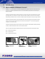
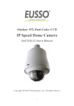
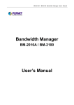
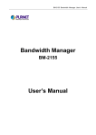
PiXORD MPEG-4 IR Network Camera P-423/426/428 User’s Manual Version: 1.4 Date: 07/27/2007 Content 1. INTRODUCTION.............................................................................................................................................................. - 3 1.1. WHAT IS MPEG-4 IR NETWORK CAMERA?............................................................................................................... - 3 1.2. KEY FEATURES ............................................................................................................................................................. - 4 2. HARDWARE INSTALLATION....................................................................................................................................... - 5 2.1. HARDWARE INSTALLATION FOR P423 ......................................................................................................................... - 5 – Part Names and Functions.......................................................................................................................................... - 5 2.2. HARDWARE INSTALLATION FOR P426 ......................................................................................................................... - 6 – Attach the IR Illuminator ............................................................................................................................................ - 6 – Part Names and Functions.......................................................................................................................................... - 7 2.3. HARDWARE INSTALLATION FOR P428 ......................................................................................................................... - 8 – Part Description & Dimension .................................................................................................................................... - 8 – Installation ................................................................................................................................................................... - 9 3. SOFTWARE INSTALLATION ...................................................................................................................................... - 12 3.1. INSTALLATION PREVIEW ........................................................................................................................................... - 12 3.2. SOFTWARE INSTALLATION ......................................................................................................................................... - 13 3.3. NETWORK CONFIGURATION ...................................................................................................................................... - 14 – Preparation before IP Assignment ............................................................................................................................ - 14 – Using IP Installer....................................................................................................................................................... - 14 4. USAGE OF WEB-BASED USER INTERFACE ........................................................................................................... - 17 4.1. BROWSE LIVE VIDEO ................................................................................................................................................. - 18 – Menu Language Selection......................................................................................................................................... - 18 – Style Selection ............................................................................................................................................................ - 18 – Video Channel Selection............................................................................................................................................ - 18 – On/Off the Audio, and Rotate the Video.................................................................................................................... - 18 4.2. RECORDING THE VIDEO AND AUDIO ......................................................................................................................... - 20 4.3. VIDEO CONFERENCE.................................................................................................................................................. - 22 – Setting for Recording ................................................................................................................................................. - 22 – Select the Remote Device ........................................................................................................................................... - 23 – Manually Set Up Additional Camera ........................................................................................................................ - 23 4.4. CONTROL PTZ DEVICES ............................................................................................................................................ - 25 5. CONFIGURATION OF WEB-BASED USER INTERFACE ...................................................................................... - 26 5.1. CONFIGURATION PREVIEW ........................................................................................................................................ - 26 5.2. CONFIGURATION OF A/V SETTING ............................................................................................................................ - 28 – General....................................................................................................................................................................... - 28 – Setting PTZ ................................................................................................................................................................ - 32 -1- – Setting External Sources ........................................................................................................................................... - 33 – Setting On Screen Display ......................................................................................................................................... - 34 5.3. CONFIGURATION OF NETWORK SETTING ................................................................................................................. - 35 – General Settings ......................................................................................................................................................... - 35 – Dynamic DNS Settings .............................................................................................................................................. - 36 5.4. CONFIGURATION OF SYSTEM ..................................................................................................................................... - 39 – System Information.................................................................................................................................................... - 39 – Time Configuration.................................................................................................................................................... - 40 – User Settings .............................................................................................................................................................. - 41 – Firmware Upgrade..................................................................................................................................................... - 42 5.5. CONFIGURATION OF EVENT ....................................................................................................................................... - 43 – General Settings ......................................................................................................................................................... - 43 – Motion Area................................................................................................................................................................ - 44 – E-Mail / FTP Settings ................................................................................................................................................ - 45 6. SPECIFICATIONS.......................................................................................................................................................... - 46 APPENDIX A UPGRADING THE FIRMWARE............................................................................................................ - 48 - -2- 1. Introduction 1.1. What is MPEG-4 IR Network Camera? The MPEG-4 IR Network Camera is an Internet-based digital video surveillance device with a built-in Web server. It uses TCP/IP to distribute compressed live video over a Local Area Network (LAN) and/or the Internet through an Ethernet connection. The MPEG-4 IR Network Camera combines the features of a network camera with an infrared illuminator to provide good image quality, even in darkness. The built-in Web server makes it possible to monitor and control it remotely while delivering clear MPEG-4 video. It's ideal for surveillance systems that operate in both day and night conditions. The MPEG-4 IR Network Camera is self-contained Web Server. Users could access the camera just like browsing website over Internet using standard browser such as Microsoft Internet ExplorerTM, and do all the management, configuration, and monitoring easily. The MPEG-4 IR Network Camera contains an MPEG-4 image compression chipset capable of delivering streaming, constant or variable bit rate MPEG-4 video over the network in real-time. There are 3 models of the MPEG-4 IR Network Camera for various environments and various distances usage. P423 – 30-Meter (Indoor/Outdoor) P426 – 10-Meter (Indoor) P428 – 100-Meter (Indoor/Outdoor) P423 30 Meter IR Network Camera P426 10 Meter IR Network Camera -3- P428 100 Meter IR Network Camera 1.2. Key Features z Day & Night functionality for 24-hours surveillance, automatically activate IR illuminator in low illumination. z Improved image quality in low-light and even in complete darkness. z Infrared radiant distance up to 30 meters (P423) / 10 meters (P426) / 100 meters (P428). z Aluminum outdoor housing with IP 66 waterproof standard (P423/P428) z PoE models (P423/P426) allow the camera to receive both data and power over a single Ethernet cable z Self-Contained HTTP Web Server providing Internet capability for remote access. z Active-X control for Microsoft Internet ExplorerTM providing maximum performance. z MPEG-4 and MJPEG video compression formats. z Supports resolution up to 30/25 fps @ Full D1 (720 x 480 / 720 x 576). z Video/Audio recording supports Windows Media PlayerTM playback. z DDNS support for dynamic IP application. z 3-layer User Security Control. z Remote Upgradeable firmware and user content pages via FTP. z Server operating control through CGI based script easy to integrate the application for users. z Hardware watchdog providing robustness system in critical environment. z Video stream supported by many media players including QuickTime -4- 2. Hardware Installation 2.1. Hardware Installation for P423 – Part Names and Functions 2 1 1. Power Cord z Non PoE model: Connects to the AC power outlet. z PoE model: The AC power is not necessary. The camera will get the power from the Ethernet cable. Please follow the below figure for the connection. 2. Ethernet Connector Standard 10 /100 Base-T port connects to a CAT5 cable with RJ-45 connector. If you are using the camera with built-in PoE, please follow the below figure for the connection. -5- 2.2. Hardware Installation for P426 – Attach the IR Illuminator 1. Put the screw (C) through washer (D) and the bracket hole (E), take the bracket (F) to fix on the screw hole (H) of camera (G). 2. Put the screw (I) through washer (J) and the bracket hole (K), take the bracket (F) to fix on the back side screw hole (L) on the IR Illuminator (A). 3. Put the DC Jack of Male connector (M) to camera and connect DC Jack of Female connector (N) to adapter. -6- – Part Names and Functions 1. Power In Jack Connects to the AC adapter. 3 2. Ethernet Connector Standard 10 /100 Base-T port, connects to a CAT5 cable with RJ-45 connector. 3. Power/Status LED Power status indicator, Constant red when power is On. 5 2 4 1 4. Network LED z Network Link (connected): Constant red. z Networks have activities: Blink red. z Data sent out from server: Blink green. z Network disconnected: Constant slow blinking green. 5. COM/GPIO Connector COM / GPIO MINI-DIN Pin No. Name Pin No. Name 1 GPIN 6 N/A 2 RXD 7 N/A 3 TXD 8 485B 4 485A 9 Video Out 5 GND -7- 2.3. Hardware Installation for P428 – Part Description & Dimension c Sun Shield f Bracket d Top Cover g Angle Adjustment Screw e Bottom Chassis h Window -8- – Installation 1. Take out the bracket from the box first. Put the power cable and Ethernet cable through the bracket and then fix it to the wall (FIG.1 & FIG.2). 2. Secondly, take out the housing and open the top cover with hexagon screw driver (FIG.3). Loosen the screws on both sides of the supporter first, use provided 1/4"-20UNC screws (black-2pcs) to fix the camera on the supporter temporarily (FIG.4). Plug and fix the power cable of camera to the terminal (FIG.5). Note: In order to adjust the camera position forward or backward later on, please do not fix the camera too tight. -9- 3. Put the power cable and Ethernet cable through the bottom of the housing (FIG.6). Plug and fix the power cable to the terminal and plug the Ethernet cable to video output of the camera (FIG.7). Next, use the provided 1/4"-20UNC screws (silver-4pcs) to fix the housing on the bracket with hexagon screw driver (FIG.8). 4. Adjust the focus and iris of the lens on the camera and then adjust the camera position on the supporter (FIG.9 & FIG.10). The camera comes with a lens of F7.5 ~ 50 mm. After finished, tighten all screws (FIG.11). - 10 - 5. Adjust VR1 to set Infrared LED activation level (FIG.12). Turn the VR1 toward "MAX" to higher the Infrared LED activation Lux level and vice versa. 6. Loosen the angle adjustment screw on the bracket to turn the housing to the desired angle and then tighten the screw (FIG.13). 7. Replace the top cover and tighten the screws (FIG.14 & FIG.15). - 11 - 3. Software Installation 3.1. Installation Preview There are 2 mains steps required to perform a successful installation: z Software installation z Network configuration Software installation consists of the installation of software that is necessary to properly view the video from the camera or to configure the camera itself. The software includes: z IP Installer -- a utility for locating devices and configuring network settings on a LAN. z Component Installer -- installs all ActiveX components used by the device for things such as video display and configuration. z Macromedia Flash Player -- necessary for displaying some components of the Web UI. The following are not necessary, but may be used for added convenience: z Recording Software -- displaying and recording up to 16 channels simultaneously. Both the MPEG-4 and MJPEG devices are supported. z Xvid -- a MPEG-4 codec. If no other MPEG-4 codecs (ie. DivX, 3ivX, ffdshow, etc.) are installed on your computer, the Component installer will install this for you. z QuickTime or VLC -- though not necessary, this can be used for viewing the MPEG-4 stream without a Web browser. Network configuration consists of modifying the network settings for the camera in order to successfully connect to the device. - 12 - 3.2. Software Installation With the exception of the Macromedia Flash Player all the software that is necessary for the proper display and use of the MPEG-4 IR Network Camera is available on the included CD or from the Web site. For the following installation procedures it is assumed that all installation media will be taken from the CD. IP Installer The IP Installer is used to locate and configure network cameras and video servers on the LAN. This utility is useful for conveniently configuring the network settings of the caera, or for finding a device once the network settings have been modified. To install the IP Installer, from the installation CD UI, select IP installer, then follow the on screen instructions. Component Installer This will install all ActiveX components used by our devices for video display and device configuration. Macromedia Flash Player Please visit the Macromedia Web site at http://www.adobe.com/downloads/ to download and install the Flash Player. - 13 - 3.3. Network Configuration IP Installer is a utility that provides an easier, more efficient way to configure the IP address and network settings of the network camera. It even provides a convenient way to set the network settings for multiple devices simultaneously using the batch setting function. Moreover, IP Installer can save the network settings for all devices as a backup and restore them when necessary. – Preparation before IP Assignment z Always consult your network administrator before assigning an IP address to your server in order to avoid using a previously assigned IP address. z Ensure the network camera is powered on and correctly connected to the network. z MAC Address: Each network camera has a unique Ethernet address (MAC address) shown on the sticker of the camera as the serial number (S/N) with 12 digits (e.g. 000429-XXXXXX). z z One final note, although the IP Installer is able to find and configure any network camera on the LAN except those that are behind a router, it is a good idea to set the host PC to the same subnet. In order to connect to the Web-based user interface of the network camera, the host PC must be in the same subnet. For more information about subnets, please consult your network administrator. – Using IP Installer Assigning an IP Address to P423 / P426 / P428 1. Once IP Installer has been successfully installed on the computer, double click the IP Installer icon on the desktop, or select it from Start > Programs > IP Installer. 2. The IP Installer window is displayed below. 3. Click the menu bar Tool > Search Network Device to search the network camera in the LAN. - 14 - 4. From the list, select the device with the MAC Address that corresponds to the device that is to be configured. The MAC Address is identical to the unit’s S/N (Serial Number). 5. Double click the item to open the Property Page dialog box for the selected device or click the menu bar View > Property. 6. After filling in the properties, click [Synchronize] button to complete the configuration settings and save in the network camera and PC immediately. If click [OK] button, the configuration is only be saved in the PC. - 15 - Opening the Web-based UI from IP Installer 1. To access the Web-based UI of the selected unit, run the View > Open Web on the menu bar. 2. If the device has been configured correctly, the default Web browser will open to the home page of the selected device. 3. If you find your browser is opened and automatically connected to the network camera Home Page, it means you’ve assigned an IP Address to the unit successfully. Now you can start to use the network camera. Verify and Complete the Installation from Your Browser When browsing the Home Page at the first time with the Microsoft Internet ExplorerTM, you must temporarily lower your security settings to perform a one-time-only installation of the ActiveX component onto your workstation, as described below. 1. From the Tools menu, select [Internet Options] 2. Click the [Security] tab and then click [Custom Level] button to see your current security settings. 3. Set the security level to Low and click [OK]. 4. Type the URL or IP address of your network camera into the Address field. 5. A dialog box will pop up asking if the ActiveX control should be installed. Click [Yes] to start the installation. 6. Once the ActiveX installation is complete, return the security settings to their original value, as noted above. - 16 - 4. Usage of Web-based User Interface Start your Web browser and enter the IP Address of your P423 / P426 / P428 IR Network Camera in the Address field. The Home page of the camera is now displayed. The Web UI can present up to 4 video source indicating 4 video channels. Each channel can be shown individually or in one of 4 split windows. Full Screen The status of the video stream Maximizes to view the selected channels into full screen 1 2 3 4 Video stream from camera (Local video source) External video sources Note: The displaying of channel 2~4 must be set in advance. They are configured as external video source (detail description in Chapter 5.2 Configuration of A/V settings > Setting external sources). The default is showing only the local video source in channel 1. - 17 - 4.1. Browse Live Video – Menu Language Selection The online Web-based User Interface can allow the user to select 3 different languages: English, Traditional and Simplified Chinese. Such display will not affect the original configuration for the language, allowing multiple users to have different languages concurrent views. In order to make the language change permanent, settings must be modified through the Configuration page. Menu Language Selection Style Selection – Style Selection The Web-based User Interface can allow the user to select the style to display: Simple and Graphic. Change the display style will not affect the functions of the Web UI. – Video Channel Selection The Video Channel item allows the users to select viewing 1 channel at a time or 4 channels at the same time. CH1 displays the video stream of the MPEG-4 IR Network Camera. CH2~4 display the video stream of the IP Camera or Video Server that connected the device via network. z Select “All” to display the local video stream (Channel 1) and 3 external video sources (Channel 2 ~4). z Select 1~4 to display the video stream of single channel. z Select “Actual” to display the video stream at the actual resolution. Note: the external video sources for Channel 2~4 must be set before viewing in the main page, in addition the PTZ control needs to be enabled if the video sources possess the PTZ function and will be controlled remotely. The detail description of PTZ settings will be mentioned in the later chapter. – On/Off the Audio, and Rotate the Video - 18 - The [Video Status] item allows the users to see the current settings of the selected channel. It also provides the function for audio control, video rotation and record the video/audio for the selected channel. Select the Channel Click the number on the tab, and the status for the selected channel will be displayed. The settings can be setup in Configuration page. On/Off the Audio Select [On] or [Off] button beside Audio to enable or disable the audio from the selected channel. Rotate the Video Click on [Rotation] button to temporary rotate the selected video on 90 degrees clockwise direction. This features that natural view for cameras that are hooked up on walls and/or vertical positions. Record the Video To be described next session. - 19 - 4.2. Recording the Video and Audio Before recording, you can check the settings of recorded file by clicking on [Recording Setting] item and change the setting if needed. The detail settings can be changed in Video Conference page. z z With factory defaults, the recorded file will be saved in a folder named C:\MVS\Recfile\pppp\CHx\ ♦ pppp : The model number of the device ♦ x : The number of the recorded channel The default filename will be named under Locals_Rec- yyyymmdd-hhmmss.avi ♦ yyyy : Current Year ♦ mm : Current Month ♦ dd : Current Date ♦ hh : Current Hour ♦ mm : Current Minute ♦ ss : Current second - 20 - To record the video and audio: 1. Click the [Video Status] item. 2. Click the channel number on the tab. 3. Click on [Record] button, it will start to record live video and audio of the selected channel. A “REC” message will display on the video. 4. The Web UI can record multiple channels at the same time. To record the other channel, just repeat the step 2 and 3. 5. To stop the recording, select the channel from the tab and then click [Stop Rec] button, the “REC” message will disappear and the recording is stopped. z The file will be saved as an AVI file, which can be play back with most media players including Windows Media TM Player . z The video is always recorded with the actual direction. It will not be affected by the rotation of viewing. - 21 - 4.3. Video Conference Click [Video Conference] to open the conference page. Rotate this video for viewing Click this button to open the Configuration page Click this button backs to the Home page On/Off the audio of this video stream Setting Configure the settings for Recording Record Stop Start recording Stop recording Camera Select the remote device – Setting for Recording You can change the settings for recording by clicking on [Setting] button in Location window. z Reserve Space: Set the total file space for the recording. z Max File Length: Set the file space that a single will be using. z Save File Path: Indicate which folder should be the file saved to. z Location File Name: Input the name for the file that recorded from the location device. z Remote File Name: Input the name for the file that recorded from the remote device. z Cycle Recording: This feature indicates if the old space should be used or not for the recording. Make a - 22 - checkmark in order to enable this function. If you enable this feature, old files will be deleted z Sync to TimeStamp : This feature enables the file to be saved according to the time. When the video file is displayed, the video will make a match between the frames and the time. z Apply: Click this button to save the changes made. z Return: Click this button returns to the live video of the location device. z Record/Stop: Click [Record] button to start recording. Click [Stop] button to stop the recording. – Select the Remote Device Click on the arrow button and select the camera from the pull-down list, the video of the remote device will be displayed. There are 4 cameras can be selected as the Remote device. The first three are set up in the Configuration page; the last one can be set up by clicking [Camera Manual Setting] button. If the remote device is a PTZ model or controls a PTZ, click [Open PTZ] button to open a PTZ control panel to control the device. See 4.4 Control PTZ Devices for the instruction. – Manually Set Up Additional Camera This feature allows the user to temporary set an additional video source for the remote device. Note: This camera will be removed after leave or close the Web page. Click on [Camera Manual Setting] button on the Remote window, and set up the following settings: z IP address: Enter the IP address of the external source. z Http Port: Enter the port number of the external source. z Username/Password: Enter the respective Username and Password if applicable. If no user has been set for the device, the default value should be root and pass respectively. z Video Channel: If the selected camera is connected to a Video Server, select the channel of the Video Server. z Video Type: Select MJPEG or MPEG4. The type must match the external source provided. z Rotation: Rotate the video for view. Rotation degrees run from 0 to 270 degrees. ♦ 0: 0 degree ♦ 1: 90 degrees - 23 - ♦ 2: 180 degrees ♦ 3: 270 degrees z RTSP Port: Enter a RTSP Port used for streaming in case the external source is a MPEG4 device. z Name: Enter a name for the external source. z PTZ Model: Enter a PTZ model in case the external source is a PTZ model or controls a PTZ. z Product Type: Select from MJPEG or MPEG4 Video Servers or IP Cameras. Please refer to the original document of the device for a better description. z Apply: Click this button to save the changes made. z Test: Click on this button to validate the video connection and the live video will be displayed if the settings are correct. z Return: Click this button returns to the live video of the remote device. - 24 - 4.4. Control PTZ Devices There are two items allows user to open the PTZ control panel to control the PTZ devices: z Click on [CH2~4 PTZ Control] item on the main page: This function allows the users to do the PTZ control in case the external source on channel 2 ~ 4 is a PTZ model or control a PTZ. z Click on [Open PTZ] button on the Video Conference page: This function allows the users to do the PTZ control in case the remote device is a PTZ model or controls a PTZ. Note: 1. The two items are available when the PTZ controlling of external video sources is enabled. 2. If none of the external sources has PTZ capability, the PTZ control panel below will not appear while the two items above are available to choose. To control the PTZ device, follow the description shown on below: Selecting Preset Point Click on the arrow button and select the desired number from the pull-down list. Pan / Tilt the Dome Camera To control the pan and tilt movement of the dome camera simply click on the buttons: z To pan or tilt, just click on the 4-directions buttons for the desired direction. z To adjust the speed of the movement, just click on the arrow button beside “Speed” and select the desired speed from the pull-down list. The higher the number selected, the faster the speed. 180o Revolve The viewing angle will o turn 180 . Zoom Lens Control z To zoom in: Click [+] button, the viewing angle becomes narrower and target will become enlarged on the screen. z To zoom out: Click [-] button, the viewing angle becomes wider and target will become smaller on the screen. Iris Control The purpose of iris control is to adjust brightness on target. It can be set as Auto Iris or Manual Iris. z Iris open: Click [+] button, to open the iris and brighten the picture. z Iris close: Click [-] button, to open the iris and reduce glare. Activate / Stop Auto Pan z Activate: Click the arrow button. z Stop: Click the rectangle button. Focus Control The focus function can be set as Auto Focus or Manual Focus. z Manual focus near: Click [+] button, the target will become farther. z Manual focus far: Click [-] button, the target will become nearer. - 25 - 5. Configuration of Web-Based User Interface The Configurations of the MPEG-4 IR Network Camera are presented as links in the margin of the Configuration Page. Simply click the relevant link for the settings you want to configure. 5.1. Configuration Preview A/V Settings Functions General PTZ Settings Description Set the parameters of video and audio, and adjust the image quality of the video. This function is unavailable for the MPEG-4 IR Network Camera. Set the video source for channel 2 to 4, using network connection External Sources (IP Address). If the video source is a PTZ device, setup the parameters of the PTZ device here. On Screen Display Set the text and location to display on the video. Functions Description Network Settings General Assign an IP Address and configure the relevant network parameters to the device. The DDNS (Dynamic Domain Name Service) is used to access the DDNS MPEG-4 IR Network Camera with an easy memorized name such as http://demo.ddns.com instead of http://61.220.235.172. System Functions System Information Description Set various information about the name of the device and the language type, etc. - 26 - Time Configuration Set the Date and Time of the device. User Create and delete users and passwords. Firmware Upgrade Update system firmware. Functions Description Event General Motion Area Email / FTP Set the trigger for the event and the action when an event is triggered. Decide the motion area where the event will be taken. Set the account information/authorization for Email and FTP which will be the action respond to the triggered events. Others Functions Description Live Returns to the Live Video display on Home page. Reboot Closes the Web browser window and reboots the device. - 27 - 5.2. Configuration of A/V Setting – General Basic A/V Settings: z Audio: Enables and Disables the audio stream. Note: Since the MPEG-4 IR Network Camera is designed for long distance monitoring, the built-in microphone is hard to receive the audio from the target actually, we recommend disable the audio. z Resolution There are 3 different resolutions to choose from: ♦ D1: 720x480 NTSC / 720x576 PAL (DVD Standard resolution) ♦ SIF: 352x240 NTSC / 352x288 PAL ♦ QSIF: 176x112 NTSC / 176x144 PAL z Frame Rate: The frame rate can be set between 5 to 30 FPS. z Encoder Format Format can be selected for: ♦ MPEG4 constant bitrates: Select MPEG4 and CBR. ♦ MPEG4 variable bitrates: Select MPEG4 and VBR ♦ Motion JPEG. - 28 - z Bitrate For Motion JPEG format, there are 4 variable bitrates between Low and High quality. For MPEG4 format, there are 12 different constant bitrates (CBR) to choose from 64Kbps to 4Mbps, and 4 variable bitrates (VBR) between Low and High quality. If you are planning on using the device on an Internet connection, it is recommended that you select a constant bitrate that corresponds to your actual upload speed. It is also recommended that you modify the frame rate and resolution as well, otherwise the video stream may become blocky or otherwise distorted. The recommended settings for low-speed network connection are as follows: ♦ 64Kbps: ♦ 128Kbps: recommended settings are [QSIF, FPS<15] ♦ 256Kbps: recommended settings are [SIF, FPS<10] ♦ 512Kbps: recommended settings are [SIF, FPS<15] ♦ 768Kbps: recommended settings are [Full D1, FPS<10] ♦ 1Mbps: recommended settings are [QSIF, FPS<10] recommended settings are [Full D1, FPS<15] For higher frame rate use a variable bitrate instead. However, this is not recommended for Internet use. ♦ Average Quality is recommended if the VBR is selected. ♦ For Good Quality, full resolution (D1) and full frame rate (30/25 fps) it is recommended that not more than 4 users connect simultaneously. ♦ For High Quality, full resolution (D1) and full frame rate (30/25 fps) it is recommended that not more than 2 users connect simultaneously. z Auto adjusts the frame rate under high-traffic icon: z When we enable this icon, system will auto detect the frame rate while using on the high-traffic networking environment. z Apply: Click this button to save the changes made. - 29 - Advanced A/V Settings: z Interlacing There are 2 modes available: Interlaced or Progressive. Interlaced mode is a storage mode. An interlaced video stream contains fields rather than frames, with each field containing half of the lines of a frame. A progressive video stream consists of only full frames. Interlaced video streams can bring a lower bitrate but may cause lower quality. z TV Standard: This is the read-only information, system will auto detect TV standard mode. z Sequence Mode There are 2 different modes available: ♦ I-frames only ♦ I-frames and P-frames P-frames, or predictive frames, are predicted based on prior P or I-frames plus some additional data. They have a much higher compression ratio than I-frames. I-frame only mode has very little compression resulting in large file sizes. I-frame and P-frame mode offers relatively good compression with medium file sizes. Although this requires more work on the host PC to decode the video. - 30 - z GOP Size: GOP stands for Group of Pictures. It defines the number of frames from one I-frame to the next. Since an I-frame uses very little compression, while P/B frames use much higher compression, a larger GOP size, results in smaller file sizes. For more information about I/P/B-frames, see below. For MPEG-4 there is no maximum GOP size defined. It can be as low as 1 V just an I-frame - or into the thousands. However, as the GOP size increases, the compression increases, and therefore the more likelihood of errors. A higher GOP size also results in higher buffering times. For DVDs the GOP size is 15. The default on the network camera is set to 60, which offers fair compression with a low likelihood of errors. z Peak Bitrate: This is used to set a maximum bitrate that can be achieved. This is useful for setting bitrates between the values that are available from the Video Encoder bitrate list. z Apply: Click this button to save the changes made. Image Adjustment: z Contrast, Brightness, Hue and Saturation: The value can be adjusted from -100 through 100. z Rotation: Rotation degrees run from 0 to 270 degrees for a permanent digital position. 0: 0 degree 1: 90 degrees 2: 180 degrees 3: 270 degrees z Auto Electronic Shutter: Enable/Disable the auto electronic shutter. z Backlight Compensation: Enable/Disable the backlight compensation. z Load Default: Click this button to set the image adjustments back to factory default. z Save: Click this button to save the changes made. - 31 - – Setting PTZ z PTZ Model: Support some kinds of PTZ models to control remote devices. Note: If your PTZ devices don’t support these models on the menu list, please contact with your distributor. z Camera ID: Define camera ID to connect video servers when using multi PTZ devices. z Serial Mode: Select the serial mode to RS232 or RS485. z COM port: This the read-only information and it will auto detect the COM port. z Serial databits, Serial baud rate, Serial stopbits and Serial Parity: Every PTZ device has independent PTZ control protocol; please refer the PTZ product manual to check these settings. If a PTZ model is applied in this page, a PTZ control icon will be displaying in the main page. It is for the user facility to “PTZ” the camera while viewing. - 32 - – Setting External Sources z Video Select: Select the channel this external source will be displayed. z IP Address: Enter the IP address of the external source. z Video Channel: If the selected camera is connected to a Video Server, select the channel of the Video Server. z Http Port: Enter the port number used for the external source. z Username/Password: Enter the respective Username and Password if applicable. If no user has been set for the device, the default value should be root and pass respectively. z Video Type: Select MJPEG or MPEG4. The type must match the external source provided. z Rotation: Rotation degrees run from 0 to 270 degrees for a permanent digital position. 0: 0 degree 1: 90 degrees 2: 180 degrees 3: 270 degrees z PTZ Model: Enter a PTZ model in case the device is a PTZ model or controls a PTZ. z Name: Enter a name for the external source. z RTSP Port: Enter a RTSP Port used for streaming in case the external source is a MPEG4 device. z Product Type: Select from MJPEG or MPEG4 Video Servers or IP Cameras. Please refer to the original document of the device for a better description. z Apply: Click on this button to save the changes made. z Test: Click on this button to validate the video connection and the live video will be displayed if the settings are correct. - 33 - – Setting On Screen Display z On Screen Display: Select Enable/Disable to display/not display the text over the video. z OSD Text: Fill in the text string to display. The valid characters are a – z, A – Z, 0 – 9, !, @, #, $, %, &, *, (, and ). Note: The maximum display block area is 12X4 characters. String length more than 12 will feed to next line, and totally 4 lines available. More than 4 lines will strip off. z OSD Coordinate X / Y: To change the location of text, just fill in the X and Y coordinate. z Display Font Grey Level: Change the color of the displayed font. z Apply: Click this button to save the changes made. - 34 - 5.3. Configuration of Network Setting – General Settings z MAC Address: Display MAC address for this device. It’s read only. z IP Address: The IP address of the network camera. z Subnet Mask: Subnet mask of your LAN. Note that the IP Address above and Gateway IP Address below should be in the same subnet. z Device Name: Assign a name for the network camera. z Gateway Address: The gateway IP address for the network segment to which the device is connected. This device traffic to Internet should go through Gateway, if not setting this, only Intranet (LAN) can be accessed. z DNS Address 1, 2 and 3: The DNS server IP address used for resolving domain names to IP addresses. DNS Address 2 and 3 are optional. z IP Setting Mode Static IP – Manually assigned IP address. DHCP – If there is a DHCP server installed on your LAN, you can select DHCP to automatically assign an IP address for the device and obtain default gateway, and DNS server. z HTTP Port: Specify the HTTP web server listen port for client (browser) connection. Default uses port 80 (HTTP standard port), valid range from 0 ~ 65535. - 35 - Note: Before changing the listen port, user must add a port directive “:” in browser URL in order to get correct connection. (i.e. http://<IP>:<Port> , e.g. http://192.168.0.200:8000) to access the device with IP 192.168.0.200 and port with 8000). These features enable user to use the device behind NAT or IP Sharing devices which could access up to 65536 network cameras with one IP Address. z RTSP Port: The port on which the device will receive RTSP (streaming video) requests. z Apply: Click this button to save the changes made. – Dynamic DNS Settings The DDNS (Dynamic Domain Name Service) is used when users want to access the network camera with an easy memorized name such as http://demo.server.ddns.com instead of http://61.220.235.172. This service could be useful when the network camera is located behind Dial-up ADSL or IP sharing devices, which does not have fix IP address, then it’s impossible to reach the network camera from Internet. When the network camera enables the DDNS service, it will “register” to the DDNS server with its information, such as server name to access, router virtual port number and updated frequency, etc.Then network camera automatically “update” to the DDNS server by a fix frequency, so even IP is changed by ISP, the DDNS server still could get and update internal database. Then, once users access from Internet with its register name, e.g. if registering with server name “demo” to DDNS server “server.ddns.com”, the network camera could be accessed by http://demo.server.ddns.com. The system provides two ways for the DDNS settings: DDNS Settings 1: This is a public DDNS server that it provides DDNS service without registering any information. z Dynamic DNS Settings 1: Select [Enable] if you wish to activate the DDNS service. - 36 - z Device Name: Specify server name. This name setting also used by the DDNS service to recognize each server. E.g. if configure name as “demo” to DDNS address “server.ddns.com”, then this network camera can be accessed by URL http://demo.server.ddns.com after register to the DDNS server. z DDNS Server Address: Specify address of the DDNS server. Input “ddns.pixord.com” will use the service provided by PiXORD Company. z DDNS Connection Port : Specify the DDNS server listen port, and the default is “80” z Router Incoming Port: Specify your router listen port for the DDNS server to redirect. The router may configure the different port for incoming (Internet request) and outgoing (Intranet request), e.g. it may configure to redirect Internet HTTP (port 80) request to Intranet port 8000, then, in this case, we must configure the “Router Incoming Port” to 80, and inside the network camera Network Settings should set HTTP port with 8000. z Update Time: Specify the network camera updated frequency in seconds, and the default is 600 (10 minutes) in a range of 300 to 2073600 seconds (576 hours), this is interval that network camera will automatically send an updated packet to the DDNS server. z DDNS Message: Return messages from remote DDNS server, and some hints may help to diagnostic the reason if register fails. ♦ DDNS addr. CGI fail: It means that network camera can’t communicate with Internet world. Make sure your Network Settings has correct subnet mask and default gateway, and DNS1 setting is valid and reachable. ♦ Already registered: Another user had registered this name; please change your register name by changing “Device Name”. z Apply: Click this button to save the changes made. DDNS Settings 2: This is not a full public DDNS server that it provides DDNS service and must register some information in the server. z Dynamic DNS Settings 2: Enable or Disable the DNS services. - 37 - z DDNS Host Name: Specify the DDNS server host name. z Account ID: Specify the account that is registered in the DDNS server. z Password: Specify the password that is registered in the DDNS server. z Update Time: as previous described. The default update time here is 2073600 seconds. z Apply: save the changes made. Example: To setup a network camera (IP address 192.168.0.200) behind a dialup ADSL router, and wish to access by name http://demo.ddns.pixord.com. And, the procedure is as below: 1. Configure the ADSL router with PPPoE enable, assume the IP of the router is 192.168.0.254, and subnet mask is 255.255.255.0 2. Go into "Virtual Server" or "Port Forwarding" configuration page in the ADSL router, set Port 80 to server IP 192.168.0.200 3. In Network Settings > General page of the network camera, configure the settings with IP address 192.168.0.200; subnet 255.255.255.0; DNS1 with valid DNS address such as 168.95.192.1 or 168.95.1.1; gateway IP address with 192.168.0.254 (router’s IP); HTTP port with port 80. 4. Configure the Device Name with “demo”. 5. Configure Dynamic DNS Settings with Enabled; DDNS Server Address with “ddns.pixord.com”; DDNS Connection Port with port 80; Router Incoming Port with 80; and Update Time with 600 (10 minutes). Finally, clicks [Apply] button. 6. If DDNS message success, then enter URL http://demo.ddns.pixord.com on browser. Consequentially, it will show the home page of the network camera. - 38 - 5.4. Configuration of System – System Information z MAC Address: Display MAC address for this device. It’s read only. z Language: Alternative language option. User may change the language of web contents for different application. z Description: Useful as an administrative identifier. Does not affect the operation of the device. z Location: Useful for identifying the position of the device. Does not affect the operation of the device. z Model: Displays the model number for the device. z Firmware Version: Display firmware version information. z Load Default: Click this button to restore the settings back to factory default. z Apply: Click this button to save the changes made. - 39 - – Time Configuration z Time Mode ♦ Synchronize with NTP server: Synchronize the current time with a NTP server over Internet. ♦ Set Manually: Manually set the time. Click on [Synchronize with computer time] button to set the date/time of the network camera as your PC’s, or Set the date and time by clicking on the arrow button beside each field and select the value from the pull-down list. Click on [Apply] button to save the configuration. z Time Zone: Click on the arrow button and select the appropriate time zone from the pull-down list. z NTP Server 1, 2 and 3: Assign the NTP servers to use for time synchronization. A list of NTP servers can be found at: http://www.eecis.udel.edu/~mills/ntp/clock2a.html z Apply: Click this button to save the changes made. - 40 - – User Settings Add User To add a user, enter the user name and password in the respective fields. Select the [Group] and the permission of each channel, and then click on [Add User] button. z The user in Administrator group has all permission to operate the device. z The user in General group can be configured to have limited permission to operate the channels. Delete User To remove a user, select the user from the list, and then click on [Delete User] button. Note: z Totally 10 users can be added. z The first added user must have administrative right (Administrator group), and must be the last one to be removed. z The username and password cannot contain the “:”, “,” characters. And the length must be between 1 and 7 characters. z The user cannot be modified, to change the data of the user, just remove it and then add it with the modified data. - 41 - – Firmware Upgrade z Click on Browse and a window will pop-up in order to let you locate the firmware file under the name of flash.bin. z Once you have selected the file and clicked on Accept, click on Update, the message below shows up. Click OK to confirm and proceed with the firmware upgrading. z The device will be upgraded with the firmware automatically, and it will reboot by itself. - 42 - 5.5. Configuration of Event – General Settings z Trigger: System provides “GPIN” and “Motion Detection” to trigger events. ♦ GPIN & GPIO Input Status: They are auto detected to display the status. ♦ Motion Detection: When user would like to use “Motion Area” function and this checkbox must be enabled. z Action: Select the actions when an event is triggered. ♦ FTP Image: When an event is triggered, the sanpshot of video will be send to the indicated FTP site. Please set the FTP site in “FTP Setting” function. ♦ Mail Image: When an event is triggered, the sanpshot of video will be send to the indicated Email address. Please set the Email address in “E-Mail Setting” function. ♦ GPOUT: It is auto detected to display the status. ♦ Relay Out: Turn “Off” or “ON” for relay out. ♦ Alert Message Status: They are auto detected to display the status with the recording application software. z Apply: Saves the changes made. - 43 - – Motion Area The “Motion Detection” icon (Configuration>Event>General>Trigger) must be enabled when use this function. To set the area on video for motion detection: 1. Use Mouse to drag out a detection area on the video. 2. Left-click the area and drag the corner to change the size. 3. Right-click the area and select “Property”. 4. Check “Enable”, click “OK” and click “Apply”. Note: Green blocks indicate this area is enabled for detection. Red blocks indicate this area is not enabled for detection. z Apply: Saves the changes made. - 44 - – E-Mail / FTP Settings z E-mail Setting: The “E-Mail Image” icon (Configuration>Event>General>Active) must be enabled when use this function. z ♦ Mail From: Enter the mail address of the mail sender. ♦ Receipt To: Enter the mail address of the mail receiver. ♦ Mail Server: Enter the mail server name or IP address. ♦ Authorization: Disable or enable the security for mail authorization. ♦ Account ID & Password: Enter the user name and password for the mail sender. FTP Setting: The “FTP Image” icon (Configuration>Event>General>Active) must be enabled when use this function. z ♦ Host Name: Enter the IP address of the FTP server. ♦ User Name & Password: Enter the user name and password for the FTP server. ♦ Mail Server: Enter the mail server name or IP address. ♦ Authorization: Disable or enable the security for mail authorization. ♦ Account ID & Password: Enter the user name and password for the mail sender. Apply: Saves the changes made. - 45 - 6. Specifications System Model P426 (10M IR Camera) P423 (30M IR Camera) P428 (100M IR Camera) CPU 32-Bit RISC Processor ROM 4MB Flash ROM RAM 32MB SDRAM Watchdog Chip to monitor system voltage tolerance and abnormal program execution Image Compression MPEG-4 Simple Profile (SP), JPEG, MJPEG Resolution Full D1 (4SIF): NTSC = 720 x 480; PAL = 720 x 576 SIF: NTSC = 352 x 240; PAL = 352 x 288 QSIF: NTSC = 176 x 112; PAL = 176 x 144 Bit Rate 16K ~ 4M bits/sec (CBR/VBR configurable) High quality VBR settings for MJPEG can reach to 10Mbps Video Adjustment Brightness, Contrast, Hue, Saturation, Frame rate, Bit rate (Constant Bit Rate (CBR), Variable Bit Rate (VBR) w/ quality levels), Group of Pictures (GOP) size, Frame Sequence (I-Frame, I-Frame/P-Frame), Interlaced/Progressive Scanning Video Performance Up to 30(NTSC) / 25(PAL) frames per second Network Interface 10/100 Base-T Ethernet Protocols TCP(UDP)/IP, ICMP, HTTP, TFTP, FTP, Telnet, SMTP, DHCP, NTP, DNS, DDNS, RTSP, RTP/TCP(UDP) Recording Directly from Web UI while viewing the live video stream Recording Software Installation Software IP Installer (Win32 Application) Firmware Upgrade Local or remote software upgradeable using FTP; Customized Web UI upgradeable via FTP and Telnet Client PC Requirement Security Connectors Computer: Pentium 4 2.0GHz or equivalent, 512MB RAM Operating System: Microsoft Windows 98se/Me/2000/XP Web Browser: Microsoft Internet Explorer 5.x or above Software Required: Microsoft DirectX 9.0c, Macromedia Flash 6, MPEG-4 Software Codec Multi-tiered access control for configuration Network: 1x RJ-45 Network: 1x RJ-45 connector connector Power:1x AC Cord Power:1x DC IN Indicators: 2x LEDs I/O: 1x COM/GPIO - 46 - Camera Model P426 (10M IR Camera) P423 (30M IR Camera) P428 (100M IR Camera) System NTSC / PAL auto detection Image Device 1/3” Sony SuperHAD CCD Total Pixels NTSC:768(H) x 494(V) PAL: 752(H) x 582(V) Resolution More than 540 TV Lines Horizontal & Vertical Synchronization NTSC:15.734KHz, 60Hz PAL: 15.625KHz, 50Hz Synchronization Internal Infrared Radiant Distance 10 meters 30 meters 80 ~ 100 meters Infrared LED 840nm / 20Units CDS Auto Control 850nm / 7Units CDS Auto Control 850nm / 17Units CDS Auto Control Minimum Illumination Normal: 0.2 Lux at F1.2 IR On: 0 Lux at F1.2 Normal: 0.2 Lux at F1.2 IR On: 0 Lux at F1.2 Normal: 0.2 Lux at F1.2 IR On: 0 Lux at F1.2 S/N Ratio More than 48dB (AGC Off) More than 48dB (AGC Off) More than 48dB (AGC Off) Back Light Compensation ON / OFF selectable ON / OFF selectable ON / OFF selectable Auto Electronic Shutter ON / OFF selectable ON / OFF selectable ON / OFF selectable Gain Control Average AGC Average AGC Average AGC White Balance Auto Auto Auto IP66 Standard IP66 Standard Water Proof Standard – Power Supply Non PoE model: Input 90V ~ 240V AC Output 12V DC PoE model: Built-In PoE (IEEE 802.3af) Non PoE model: Input 90V ~ 240V AC PoE model: Built-In PoE (IEEE 802.3af) Input 90V ~ 240V AC Power Consumption 6W (IR Off) / 7.5W (IR On) 6W (IR Off) / 8.5W (IR On) 8W (IR Off) / 20W (IR On) Operation Temperature 5oC ~ 50oC -20oC ~ +60oC -20oC ~ +60oC Operation Humidity 20% ~ 80% 0% ~ 90% 0% ~ 90% Dimension (L x W x H) 168mm x 77mm x 54mm 235mm x 98mm x 90mm Φ134mm x 318mm(L) Weight 1300 g (With Stand) 1260 g 3300 g - 47 - Appendix A Upgrading the Firmware The MPEG-4 IR Network Camera firmware is contained in Flash Memory, a silicon chip allowed to be erased and re-written. It provides an easy way to update the firmware without change any parts; just simply load the newest firmware from network. The following procedures are to update the firmware: Check firmware Version Open the home page of MPEG-4 IR Network Camera in your web browser, go into Configuration -> System -> System Information, you will see the version--" Firmware Version=2.11R27.04.PN", which indicates the currently firmware version is 2.11. Upgrade Procedure via FTP 1. Download the newest firmware and unzip it into your local drive, for example "C:\temp". Then, confirm the "flash.bin" file exists in this folder. 2. Restart the network camera by clicking on the <Reboot> button on Configuration page. Caution: You must reboot the network camera before doing the following procedures; otherwise, some occasional internal conflicts may endanger the Flash devices. 3. Start the FTP session and log in to the network camera. For example, in our case for Windows XP: Enter DOS by Start > All Programs > Command Prompt" Change to the folder where the latest flash.bin exist. Start ftp session by enter “ftp <Network camera’s IP Address> Enter "root" as USERNAME, "pass" as PASSWORD if no user in User List record .In case any user list exists, you will have to use your administrator's USERNAME and PASSWORD to login. 4. Set FTP to binary mode using the command "bin". In FTP session window, Enter "bin" 5. Upload the firmware into the network camera by FTP "put" command. In FTP session window, enter "put flash.bin" In FTP session window, enter "bye" to quit FTP session. 6. FTP session may freeze for around 1 minute to transfer and automatically upgrade the firmware. During that time, ping the network camera until get constant reply, which means system had completed upgrading and rebooting, then open browser to verify the firmware version been updated. Note: If FTP session quits immediately after issued by command, you should continue pinging the network camera instantly. If the network camera replies to the ping command right after pinging, it means the network camera may not enter the self-programming stage to update the firmware. If not updated, then you should reboot the network camera and back to step 3 to try again. - 48 - For example, the network camera IP address is 192.168.0.200, then C:\Documents and Settings\Administrator>cd \temp Keyin the path stores the “flash.bin” C:\temp>ftp 192.168.0.200 Connected to 192.168.0.200. 220 192.168.0.200 Keyin this command, change the IP to yours Network camera FTP server ready. Input the account, default is “root” User (192.168.0.200:(none)): root 331 Password required for root. Input the password, default is “pass” Password: 230 User root logged in. Keyin this command ftp> bin 200 Type set to I. Keyin this command ftp> put flash.bin 200 PORT command successful. 150 Opening BINARY mode data connection for flash.bin 226 Transfer complete. ftp: 2097152 bytes sent in 10.11Seconds 207.43Kbytes/sec. ftp> bye 221 Goodbye. Keyin this command <=Quit ftp session immediately <=if the window is frozen, please open another dos session C:\temp>ping -t 192.168.0.200 Keyin this command and wait the upgrade is complete. Pinging 192.168.0.200 with 32 bytes of data: Request timed out. These messages means the upgrade is finished Request timed out. Reply from 192.168.0.200: bytes=32 time=2ms TTL=255 Reply from 192.168.0.200: bytes=32 time=1ms TTL=255 Reply from 192.168.0.200: bytes=32 time<10ms TTL=255 Press Ctrl+C to terminate the detection Ping statistics for 192.168.0.200: Packets: Sent = 13, Received = 5, Lost = 8 (61% loss), Approximate round trip times in milliseconds: Minimum = 0ms, Maximum = 2ms, Average = 0ms Control-C ^C C:\temp> Note: Flash products can become damaged if the updating operation is not performed correctly. So please follow up above procedures carefully. - 49 -