1
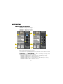
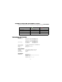
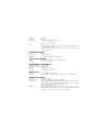
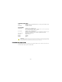
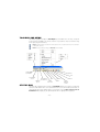
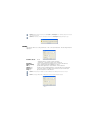
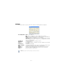
NDL8000
TrueGraph
Data Logger & Software
1UAINDL800002
User’s Manual
English
www.algodue.com
Rev. 002 - 12/04/2006
Data Logger
NDL8000 series
&
TrueGraph
Management software
USER’S MANUAL
EDITION: APRIL 2006
Limitation of Liability
The Manufacturer reserves the right to modify the devices or the device specifications identified in this manual without notice.
In the absence of written agreement to the contrary the Manufacturer assumes no liability for the Manufacturer applications assistance, customer’s system design,
or infringement of patents or copyrights of third parties by or arising from the use of devices described herein. Nor does the Manufacturer warrant or represent that
any license, either expressed or implied, is granted under any patent right, copyright, or other intellectual property right of the Manufacturer covering or relating
to any combination, machine, or process in which such device might be used.
EXCEPT TO THE EXTENT PROHIBITED BY APPLICABLE LAW, UNDER NO CIRCUMSTANCES SHALL THE MANUFACTURER BE LIABLE FOR CONSEQUENTIAL
DAMAGES SUSTAINED IN CONNECTION WITH SAID PRODUCT AND THE MANUFACTURER NEITHER ASSUMES NOR AUTHORIZES ANY REPRESENTATIVE
OR OTHER PERSON TO ASSUME FOR IT ANY OBLIGATION OR LIABILITY OTHER THAN SUCH AS IS EXPRESSLY SET FORTH HEREIN.
All trademarks, in this manual, are property of their respective owners.
The information contained in this document is believed to be accurate at the time of publication, however, the Manufacturer assumes no responsability for any
errors which may appear here and reserves the right to make changes without notice.
TABLE OF CONTENTS
NDL8000
INTRODUCTION ........................................................................................................................................................................ 1
SYMBOLS................................................................................................................................................................................... 1
DESCRIPTION ............................................................................................................................................................................ 2
FRONT PANEL DESCRIPTION ........................................................................................................................................... 2
KEYS ................................................................................................................................................................................... 3
NDL8001-VAC & NDL8003-VAC MODELS FOR VOLTAGE MEASUREMENT ................................................................... 3
NDL8001-AAC & NDL8003-AAC MODELS FOR CURRENT MEASUREMENT................................................................... 3
COMMON FUNCTIONS ...................................................................................................................................................... 3
CONNECTIONS ......................................................................................................................................................................... 4
WIRING MODES ................................................................................................................................................................. 4
RS232 SERIAL COMMUNICATION PORT .......................................................................................................................... 5
POWER SUPPLY ........................................................................................................................................................................ 5
LOW BATTERY.................................................................................................................................................................... 6
BATTERY REPLACEMENT .................................................................................................................................................. 6
USE ............................................................................................................................................................................................ 7
RECORDINGS..................................................................................................................................................................... 7
DIAGNOSTIC FUNCTION (INSTRUMENT STATUS)........................................................................................................... 8
TECHNICAL FEATURES ............................................................................................................................................................ 8
FIRMWARE UPDATING............................................................................................................................................................ 10
TrueGraph SOFTWARE
INSTALLATION ........................................................................................................................................................................ 12
TOOLBAR AND MENU............................................................................................................................................................. 13
STATUS BAR ............................................................................................................................................................................ 13
INSTRUMENT MENU ............................................................................................................................................................... 14
CONNECT ......................................................................................................................................................................... 14
SETUP ............................................................................................................................................................................... 15
MEMORY........................................................................................................................................................................... 16
DATA DOWNLOADING .................................................................................................................................................... 17
INFO .................................................................................................................................................................................. 17
DATA MENU............................................................................................................................................................................. 18
OPEN ................................................................................................................................................................................ 18
SAVE DATA ....................................................................................................................................................................... 19
CLOSE .............................................................................................................................................................................. 20
TABLE ............................................................................................................................................................................... 21
GRAPHIC .......................................................................................................................................................................... 23
SLIDE DEMAND GRAPH .................................................................................................................................................. 25
USER INFORMATION ....................................................................................................................................................... 28
MIN/MAX SEARCH............................................................................................................................................................ 29
STATISTICS....................................................................................................................................................................... 30
PRINT ................................................................................................................................................................................ 31
HELP MENU ............................................................................................................................................................................. 32
HELP ................................................................................................................................................................................. 32
LINGUAGE ........................................................................................................................................................................ 32
INFORMATION.................................................................................................................................................................. 32
SHORT CUTS ........................................................................................................................................................................... 33
INTRODUCTION
This manual provides information on the installation, configuration and use of the main instrument
functions. The manual is not intended for general use, but for qualified technicians; this term
indicates a professional and skilled technician, authorised to act in accordance with the safety
standards relating to the dangers posed by electric current. Moreover, this person must have
basic first aid training and be in possession of suitable Personal Protective Equipment.
WARNING: It is strictly forbidden for anyone who does not comply with the above-mentioned requirements to install or use
the instrument.
The instrument complies with the European Union directives in force, as well as with the technical
standards implementing these requirements. It is strictly forbidden to use the instrument for purposes other than intended ones, understood by the manual content.
The information contained in this manual has been carefully checked at the time of publication.
However, the manufacturer does not accept liability for any inaccuracy, errors, missing updates,
and furthermore reserves the right to modify the instrument and / or documentation without prior
notice.
The information herein contained shall not be shared with third parties. Any duplication of this
manual, either partial or total, not authorized in writing by the Manufacturer and obtained by
photocopying, duplicating or using any other electronic means, violates the terms of copyright
and it is punishable by law.
Any brand quoted in the publication belongs to the legitimate registered owner.
SYMBOLS
In the manual and on the instrument, some instructions are highlighted by graphic symbols to
draw the reader’s attention to the operational dangers. Hereby the list of used symbols:
DANGER: It indicates the possible presence of voltage exceeding 1 kV on the marked terminals (even for short periods).
WARNING: It indicates the possible occurrence of an event which may cause a serious accident or considerable damage
to the instrument, if suitable precautionary countermeasures are not taken.
ATTENTION: It indicates the possible occurrence of an event which may cause a light accident or damage to the instrument, if suitable precautionary countermeasures are not taken.
NOTE: It indicates an important information which must be read carefully.
-1-
DESCRIPTION
FRONT PANEL DESCRIPTION
The instrument is available in four different models:
• NDL8001-VAC single phase voltage
• NDL8003-VAC three-phase voltage
• NDL8001-AAC single phase current
• NDL8003-AAC three-phase current
Picture A
Picture B
Front panel description:
1. RS232 serial communication port connector
2. STATUS LED (green) and ALARM LED (red): these LED signals can have different meanings
(see sections Recordings and Diagnostic Function)
3. START/STOP key and CHECK/ENTER key: allow to start and stop a recording, and to
display (through LEDs) the instrument diagnostic
4. Inputs:
• NDL8001-VAC single phase voltage input (as pict. A but with only 2 sockets)
• NDL8003-VAC three-phase voltage inputs (as pict. A)
• NDL8001-AAC single phase current input (as pict. B but with only one connector)
• NDL8003-AAC three-phase current inputs (as pict. B)
-2-
KEYS
The keys are designed to be not much sensitive to avoid that they are pressed accidentally during carriage. Therefore,, put the finger to the centre of the key and push fairly hard.
WARNING: Do not use any hard or angular objects, nails included, to avoid a damage on the overlay layer of the key.
NDL8001-VAC & NDL8003-VAC MODELS FOR VOLTAGE MEASUREMENT
NDL8001-VAC is a single channel Data Logger for single phase voltage measurement.
NDL8003-VAC is a three channels Data Logger for three-phase voltage measurement with the
possibility of neutral connection.
Both models provide accurate True RMS calculation even by distorted waveform through the 12
bit AD Converter.
NDL8001-AAC & NDL8003-AAC MODELS FOR CURRENT MEASUREMENT
NDL8001-AAC is a single channel Data Logger for single phase current measurement.
NDL8003-AAC is a three channels Data Logger for three-phase current measurement.
Both models use, as current transducers, Rogowski flexible coils which can be connected without
any external adapter.
COMMON FUNCTIONS
The RS232 serial port, in combination with the provided TrueGraph software, allows the instrument configuration and the downloading of recorded data.
Data are recorded in a non-volatile Flash memory; therefore data are not lost even with low battery
or during its replacement.
The instrument is equipped with a 2MB of memory which can be programmed for ring or fill mode
recordings.
The measurement sampling rate can be set from 1 second to 24 hours.
MEMORY SIZE EXAMPLES
NDL8001-VAC: sampling rate 6 sec. with 1 recorded value=18 giorni circa
NDL8003-VAC: sampling rate 6 sec. with 7 recorded values=10 giorni circa
NDL8001-AAC: sampling rate 6 sec. with 1 recorded value=73 giorni circa
NDL8003-AAC: sampling rate 6 sec. with 4 recorded values=18 giorni circa
-3-
CONNECTIONS
WIRING MODES
Connections are made on the instrument front panel, as described in the following pictures.
NDL8003-VAC
Direct connection
Connection with voltage transformer
NDL8001-VAC
Direct connection
Connection with voltage transformer
NDL8003-AAC & NDL8001-AAC
-4-
RS232 SERIAL COMMUNICATION PORT
The RS232 serial port allows to connect the instrument to a PC. For the connection, use the DB9
shielded cable provided with the instrument.
POWER SUPPLY
The instrument is powered by a 9V battery, common 6F22 model; it is possible to use either rechargeable or alkaline battery: the alkaline type is suggested. During battery replacement date
and time settings are lost, while recorded data and recording settings are retained. As the instrument is not provided with a recharge circuit, batteries must be recharged using a stand alone
recharger.
The battery compartment contains a little switch; if activated,
it switches OFF the instrument, stopping all the current operations. When the instrument is not used for a long time, this
useful action grant longer lifetime to the battery.
The instrument is already provided with a new battery. To switch
ON the instrument, move the switch on the “ON” position as indicated in the picture (see on the instrument back label).
If the instrument is switched ON, the internal realtime clock is
in timekeeping mode even if no recording in progress. In this
condition, the battery lifetime is:
Ni-Cd 120 mAh minimum
Zn-Cl 300 mAh minimum
Alk 600 mAh minimum
250 days
625 days
1250 days
NOTE: The following table shows the battery lifetime of the model with three current inputs in the worst case: active instrument
recording, without active communication.
RECORDING
FREQUENCY
Ni-Cd 120 mAh
minimum
Zn-Cl 300 mAh
minimum
Alk 600 mAh
minimum
1 second
> 5 days
> 15 days
> 30 days
6 seconds
> 25 days
> 2,5 months
> 5 months
1 minute
> 2,5 months
> 7 months
> 1 year
NOTE: When the instrument is switched OFF or the battery is removed for more than 15 seconds, date and time settings are
lost. At the next switching ON, these settings must be programmed from the software.
-5-
LOW BATTERY
When a diagnostic procedure is carried out (see section Diagnostic Function), but both LEDs
are not flashing, check if the switch, inside the battery compartment, is in ON; otherwise replace
the battery.
NOTE: The programmed recording parameters and the recorded data are retained in memory even with low battery.
BATTERY REPLACEMENT
WARNING: Before removing battery or switching OFF the instrument (see section Power Supply), stop the recording in
progress. This operation avoids the loss of data.
WARNING: Before replacing the battery, disconnect all the cables from the instrument.
WARNING: Check the expiry date of the battery: do not use expired battery.
WARNING: Batteries must not be disposed in the household waste. The law requires that the consumer returns the waste
batteries either to public collection points in town or village or to any outlet selling batteries of the same kind (statutory instructions on battery disposal).
WARNING: Batteries which contain polluting substances are marked as follows:
Pb = lead battery
Cd = cadmium battery
Hg = mercury battery
NOTE: All batteries provided with the instrument do not contain polluting substances.
For battery replacement, follow the procedure below:
• open the battery compartment cover
• remove the low battery
• disconnect the connector
• connect the new battery
• insert the new battery
• close the cover
NOTE: When battery is replaced, or the instrument is switched ON again, check the instrument status with a diagnostic
function.
-6-
USE
NOTE: At the opening of the box, check that the instrument is not damaged due to transport. If the instrument looks damaged,
please contact the Technical Service.
The box must contains:
in case of NDL8001-VAC & NDL8003-VAC
• Data Logger
• n. 2/4 flexible leads with safety banana-jack ∅ 4mm EN61010 with different colors for phases and neutral
• n. 2/4 crocodile clips
• DB9 cable for RS232 serial connection
• instrument bag and accessories
• CD-ROM with TrueGraph software
• user’s manual
• battery
in case of NDL8001-AAC & NDL8003-AAC
• Data Logger
• n. 1/3 flexible transducer Rogowski
• DB9 cable for RS232 serial connection
• instrument bag and accessories
• CD-ROM with TrueGraph software
• user’s manual
• battery
RECORDINGS
The Data Logger is an instrument for measured data recording. To carry out a recording, follow
the procedure below:
• check the instrument is ON and no recording is currently set
• connect the instrument to PC, run TrueGraph software, check clock setup and carry out
the settings in Memory Setup window
• to start or stop a recording, keep START/STOP key pressed and simultaneously press
twice CHECK/ENTER key
The instrument replies with confirmation messages through the two LEDs, described in the following table.
INFO messages
ALARM (RED)
STATUS (GREEN)
START recording
5 times fast
STOP recording
once for 1 sec.
-
Recording not set
-
5 times fast
FULL memory
-
LOW BATTERY
-
once for 1 sec.
5 times fast
-7-
DIAGNOSTIC FUNCTION (INSTRUMENT STATUS)
At any time, the Data Logger allows to know the current instrument status. If CHECK/ENTER
key is pressed for at least 1 sec., the two LEDs provide a diagnostic message.
DIAGNOSTIC message
ALARM (RED)
STATUS (GREEN)
Recording in progress
5 times fast
-
once for 1 sec.
-
Recording not set
-
5 times fast
FULL memory
-
Ready to record
BATTERY LOW
once for 1 sec.
5 times fast
TECHNICAL FEATURES
INPUTS
N. of channels
Input voltage
single phase voltage
three phase voltage
single phase current
three phase current
0÷600 VAC L-N
0÷600 VAC L-L
NDL8001-VAC
NDL8003-VAC
NDL8001-AAC
NDL8003-AAC
NDL8001-VAC
NDL8003-VAC
Input sensitivity
Input impedance
Load
Frequency
0÷350 mV NDL8001-AAC & NDL8003-AAC
>1.3 Mohm
max 0.15 VA per phase
45÷65 Hz
MEASUREMENT
Accuracy
Sampling
Calculation
A/D converter
±0.5% lettura ±0.05% fondoscala
128 samplings/period for 2 waves
true RMS
12 bits
RECORDING
Parameters
NDL8001-VAC: VL1
NDL8003-VAC: VΣ, VL1-N, VL2-N, VL3-N, VL1-L2, VL2-L3, VL3-L1
NDL8001-AAC: IL1
NDL8003-AAC: IL1, IL2, IL3, IN
-8-
Memory
Memory size
Frequency
Mode
Flash type
2MBytes
1, 2, 3, 4, 5, 6, 10, 12, 15, 20, 30 sec.
1, 2, 5, 10, 15, 20, 30 min.
1, 6, 12, 24 ore (selectable)
• fill
• ring with partial overwrite of data already recorded, mantaining the recording rate previously set
• ring with partial overwrite of data already recorded, with recording rate
slowing at each cycle
COMMUNICATION PORT
Type
RS232
Power supply
from PC RS232 port
Baud Rate
from 2400 to 19200 bps, programmable
SIGNALS AND COMMANDS
Signals
n. 2 LED for operating status and battery status
Keypad
n. 2 multifunction keys
ENVIRONMENTAL REQUIREMENTS
Operating temperature -10°C e +60°C
Storage temperature -20°C e +75°C
Altitude
0÷2000 m on sea-level
Humidity
max 90% without condensation
POWER SUPPLY
Battery
Battery life
9V type (alkaline, Zn-Cl, Ni-Cd)
> 1 month with recording frequency at 6 seconds with Ni-Cd battery
MECHANICAL FEATURES
Material
autoextinguish plastic
Protection degree
IP50 (case), IP30 (opened battery compartment)
Connections
safety sockets ∅ 4mm EN61010 with different colors for phase and neutral VAC
clamp connectors ∅ inside diameter about 200mm, connection cable
I=2.5m, double insulation 600VRMS rated AAC
Size
about 110 x 80 x 40 mm
Marking
front label with electrical specifications, connections, user’s instructions;
back label with model, number, code, power supply specifications, input
specifications, memory size, battery switch description
-9-
STANDARD COMPLIANCE
Safety
CEI EN61010-1 and CEI EN61010-031 (overvoltage CAT III 600V, double
insulation - class 2)
CE Marking
93/68/EEC standard
ACCESSORIES
Transducers
Connections
PC connection
Transport
Battery
Software
Manual
NDL8001-AAC & NDL8003-AAC
tipo flessibile Rogowski, ∅ interno 200mm circa, cavo di connessione
I=2.5m, double insulation 600 VRMS rated
NDL8001-VAC & NDL8003-VAC
flexible leads with safety banana-jack 4mm EN61010 with different colors
for phases and neutral, n.2/4 crocodiles clips 30mm max width
DB9 cable for RS232 port
instrument bag
9V type
CD-ROM
paper
ATTENTION: As the flexible clamps have a low level signal, in order to grant the best measurement accuracy the instrument
has been calibrated with its own current transducers. Therefore, do not use transducers of other similar instruments to avoid
unaccurate measurements. The instrument and its transducers have the same serial number.
FIRMWARE UPDATING
To add new functions on the instrument, the firmware update can be carried out via serial communication port, using a specific software utility.
- 10 -
TrueGraph SOFTWARE
TrueGraph is the software provided with the instrument which allows the Data Logger management; it allows to:
• set the instrument parameters
• set recordings
• download recordings
• analyze downloaded or previously stored data
• display processed data in different modes (table, graphic..)
TrueGraph can be used only on IBM PC compatible in a Microsoft Windows® 98, METM, NTTM
4.0, 2000, XP environment.
INSTALLATION
To install TrueGraph it is necessary to check the compatibility between PC and software.
Minimal configuration:
• IBM PC compatible with Pentium processor
• O.S. Microsoft Windows® 98, METM, NTTM 4.0, 2000, XP
• 10MB of free space on the hard disk
• SVGA graphic board
• CD-ROM reader
• RS232 serial communication port
• keyboard and mouse
Suggested configuration:
• IBM PC compatible with Pentium III processor
• O.S. Microsoft Windows® 98, METM, NTTM 4.0, 2000, XP
• 100MB of free space on the hard disk
• SVGA graphic board
• CD-ROM reader
• RS232 serial communication port
• keyboard and mouse
To install TrueGraph on the hard disk, follow the procedure below:
1. switch ON the PC and wait until Microsoft Windows® environment has been loaded
2. insert the provided CD in your system’s CD reader
3. the automatic system starts the installation, otherwise select Run from the Windows Start
button
4. type X: \ SETUP and press <ENTER> (X identifies the PC CD-ROM drive letter). The
software installation will be carried out
5. at the end of the installation, a TrueGraph file group appears
6. to run the program, double-click on the TrueGraph icon
- 12 -
TOOLBAR AND MENU
Here below, a graphic description of TrueGraph keys and relative menu. The keys correspond
to the main items available in the menus, therefore, it is possible to carry out a function using
menu or pressing the relevant key.
NOTE: The displayed windows, described in this manual, depends on the connected instrument version. The manual refers
to NDL8003-VAC instrument.
NOTE: The keys are enabled according to the TrueGraph functions availability.
CONNECT THE
INSTRUMENT
EXIT
HELP
INSTRUMENT
SETUP
INSTRUMENT
INFORMATION
MEMORY
SETUP
SAVE
OPEN A
DATA FILE
GRAPHIC
TABLE
PRINT
SLIDE
DEMAND
GRAPH
STATUS BAR
The Status bar is displayed at the bottom of TrueGraph window. The left area of status bar
shows the serial number of the connected instrument, the used communication port and the set
communication speed (if no Data Logger is connected, the message Not connected to an
instrument will be displayed); the current data file name is displayed in the right area.
- 13 -
INSTRUMENT MENU
The instrument menu allows to set the instrument. The next pages describe the following menu
items:
• Connect
• Setup
• Memory
• Info
CONNECTION
NOTE: All instrument recordings are automatically stopped at the connection to TrueGraph. Therefore, stop all recordings,
before connecting to the software.
NOTE: Before connecting the instrument to a PC, wait until the instrument has reached the operating temperature.
Once TrueGraph has been started, automatically it searches for the available serial ports in the
PC; if a connected Data Logger is found, a confirmation window is displayed for the connection
of the instrument.
If the instrument is connected after TrueGraph running, it is necessary to use the Connect
function. The following window is displayed.
Baudrate
PC Port
Serial number
Search key
OK key
Cancel key
Help key
communication speed: 2400, 4800, 9600, 19200 bps
PC communication port where the instrument is connected
instrument serial number
start the instrument search considering the parameters set in this window
(serial number not considered)
confirm the settings and search the instrument considering the typed serial number
cancel the carried out settings and come back to the main window
provide assistance for this window
- 14 -
NOTE: During the instrument manual research with Search key, TrueGraph looks for baudrate, starting from the selected
value up to the lower value.
NOTE: After instrument connection, if the battery is lower than 10%, TrueGraph will display a warning message.
SETUP
This function allows to set the parameters on the connected instrument. The following window is
displayed.
Realtime Clock
Baudrate
KTV (1-9999)
All key
Update key
Cancel key
Help key
Mode:
• Manual: allow to set date and time manually
• Automatic: set PC date and time in the instrument
set the communication speed (bps) of the connected instrument
set the voltage transformer multiplier (see Note)
update all the parameters of this window, in the instrument
update only the modified parameters of this window, in the instrument
cancel the carried out settings and come back to the main window
provide assistance for this window
NOTE: The KTV parameter is available only if either the NDL8001-VAC or NDL8003-VAC model are connected.
NOTE: Connecting to NDL8001-AAC or NDL8003-AAC model, the following window is displayed.
- 15 -
MEMORY
This function allows to set the instrument recording. The following window is displayed.
Recording Mode
Parameters
Frequency
Clear key
Download key
Time to fill the..
All key
Update key
Cancel key
Help key
None: no recording set
Fill: stop the recording when all the available memory is filled
Ring: when the available memory is completely filled, recorded data are
partially overwritten, mantaining the set recording rate
Time Ext.: when the available memory is completely filled, recorded
data are partially overwritten, slowing the set recording rate (next value
rate is set automatically)
selectable parameters for recording (see Note)
recording frequency
reset instrument data; a confirmation message is displayed: to clear data
press Yes
download recorded data
recording time extimation based on to the selected parameters and the set rate
update all the parameters of this window, in the instrument
update only the modified parameters of this window, in the instrument
cancel the carried out settings and come back to the main window
provide assistance for this window
NOTE: Parameter fields may differ according to the instrument version/model.
- 16 -
DATA DOWNLOADING
After data downloading, a window is displayed for file saving; after this operation, another window
appears for the selection of the desired option; to confirm, press OK key.
Clear instrument memory and start.. retain the settings but memory is cleared
Clear instrument memory, reset.. clear data memory and settings
Keep memory contents and..
retain the recording, without changing the settings
INFO
This function allows to display information about the connected instrument. The following window
is displayed.
Instrument Model
Description
Serial Number
Build Year
Battery Status
Memory Status
OK key
instrument model name
instrument brief description
instrument serial number
instrument manufacturing year
battery status (100%=charge; 0%=discharge)
memory size
close the window
- 17 -
DATA MENU
The Data menu allows to manage, in different ways, downloaded and/or previously stored data.
The next pages describe the following menu items:
• Open
• Save data
• Close
• Table
• Graphic
• Slide Demand Graph
• User Information
• Min/Max Search
• Statistics
• Print
OPEN
This function allows to open a recorded data file previously saved on the hard disk. The following
window is displayed. Select the desired file and press Open.
- 18 -
SAVE DATA
This function allows to save data in Table or in Graphic mode. In Table mode, by this window,
data are saved in Data directory in ASCII format.
Save (multiple) Excel-compatible files option, if available, allows to divide data, saving
them in a number of Excel compatible files. This option is very useful since Excel is able to manage a data file with 65536 lines max, while TrueGraph data file can have more than 65536
lines; therefore, if this option is selected, the management of all data is granted, also in Excel
program.
In Graphic or Slide Demand Graph modes, the following window is displayed, to save data in
images directory in a selectable graphic format.
- 19 -
In Save as type field, click on the specific key to display the list with the available file format:
• Bitmap file (*.bmp)
• Graphic Interchange file (*.gif)
• JPEG file (*.jpg)
• Portable Network Graphic file (*.png)
After the graphic format selection, insert the name in the field name and press Save key.
CLOSE
This function allows to close the current data file.
- 20 -
TABLE
This function allows to display data in table mode.
Identification data
this area includes the programmable recording data: Title, Measurement Location, Additional Information
TrueGraph arranges data chronologically. To analyze only a part of data, follow the procedure
below:
1. to select, click on the first line of the desired area
2. keep SHIFT key pressed and select the last line of the list; the desired area will be highlighted
3. to display other table functions, click the right key of the mouse
4. a short menu, containing two items, will be displayed:
• Statistics open a window with minimum, average, maximum values of all data or the
selected one (see section Statistics)
• Display as graphics display all data or the selected one in Graphic mode (see
section Graphic)
NOTE: It is suggested to analyze in Table mode the recordings with more than 60 samplings. Otherwise, a lower value has
no sense and it can cause the ending of the program.
- 21 -
When the recording is stopped and then started again, TrueGraph shows this event displaying
a line without values; this is very useful for a prompt identification of a temporary interruption of
the recording.
- 22 -
GRAPHIC
This function allows to display data in graphic mode.
AutoScale key
Zoom all key
Statistics key
Arrow keys
Identification data
enable/disable the automatic function for scale values setup. When
the top and the bottom values of scale are not highlighted (disabled
autoscale), it is possible to set those of the vertical axis manually
display the entired graphic
open a window with minimum, average, maximum values for all the
available parameters of the displayed or selected graphic (see section Statistics)
allow to drag the graphic (left or right) to display the details (PAN
function)
this area includes the programmable recording data: Title, Measurement Location, Additional Information
- 23 -
When the recording is stopped and then started again, TrueGraph shows this event displaying
an interruption in the graphic, identified by a yellow zone; this is very useful for a prompt identification of a temporary interruption of the recording.
- 24 -
SLIDE DEMAND GRAPH
This function allows to display data in Slide Demand Graph mode. The values used for the graphic
are the result of an average values calculation on a programmable integration time.
In comparison with the Graphic window previously described, there is a further function carried
out pressing Set key. All the other functions are the same of the Graphic mode.
Set key
open the window for the slide demand setup
Demand period: integration time value for the demand value calculation
Slide step: slide step value (in minutes o seconds)
- 25 -
OTHER GRAPHIC FUNCTIONS
The available graphic parameters are displayed at the right of the graphic. Each parameter
color corresponds to the graphic line with the same color. To display the desired parameters
in the graphic, select next to the parameters.
To carry out operations only in a desired part of the graphic, follow the procedure below:
1. move the cursor on the desired graphic area
2. with the mouse, keep left key pressed, and drag the cursor until all the desired area is
selected
3. after releasing the key, a short menu, containing two items, will be displayed:
• Zoom in magnify the selected graphic area
• Statistics open a window with minimum, average, maximum values for all the
available parameters of the displayed or selected graphic (see section Statistics)
To carry out functions and operations on the graphic:
1. when the cursor is on the graphic, click on right key of the mouse
2. the following menu is displayed:
Zoom all
Statistics
Show
display the entired graphic
open a window with minimum, average, maximum values for all
the available parameters of the displayed graphic (see section
Statistics)
display a function list
Values axis labels-major: enable/disable main values on
the vertical axis
Values axis labels-minor: enable/disable secondary values
on the vertical axis
Time axis labels: enable/disable time values on the axis
Horizontal gridlines-major: enable/disable the main horizontal gridlines
Horizontal gridlines-minor: enable/disable the secondary
horizontal gridlines
Vertical gridlines: enable/disable vertical gridlines
Graph Title: enable/disable graphic title
- 26 -
Show cursor
Colors setup
Measurement Location: enable/disable measurement location
Measurement Information: enable/disable measurement
information
Statistics: enable/disable Statistics table next to the graphic
enable/disable the cursor in the graphic and the window with cursor data (Ctrl+T)
parameters color setup
H.Gridlines setup horizontal gridlines setup
Manual: manual setup of horizontal gridlines
Automatic: automatic setup of horizontal gridlines
- 27 -
V.axis s/e setup
vertical axis start/end setup
Manual: manual setup of absolute values
Automatic: automatic setup with percentage values
USER INFORMATION
This function allows to set the user identification data (Title, Measurement Location, Additional Information). The following window will be displayed.
The information in this window is displayed in Table or Graphic mode; moreover, this information is
shown at the next opening of the file, if it was previously saved.
- 28 -
MIN/MAX SEARCH
This function allows to display the minimum and maximum value of a single parameter. Select
Min/Max Search from Data menu, and a list of the available parameters will be displayed. To
disable this function, select None.
Once the desired parameter has been selected, the minimum and maximum value will be identified
in different way, depending on the data display mode (Table, Graphic, Slide Demand Graph).
In Table mode, it will be automatically displayed the area where the first extreme value is found
(min or max). According to the type of value (min or max), the cell change the color; a blue cell
identifies a minimum value, while a red cell identifies a maximum value. At the top of the table,
next to the Identification data, the selected parameter and the type of extreme value will be displayed (min o max).
Next extreme value key
allow to toggle between the minimum and maximum value
- 29 -
In Graphic mode, when Min/Max Search function is enabled, TrueGraph looks for the extreme values in the displayed graphic; the minimum value and the maximum values are identified
by two yellow indicators which contain value, type of value, date and time.
STATISTICS
This function allows to calculate and display minimum, average and maximum values for all the
available parameters of all data or the selected one. This window is opened when the Statistics
function is selected in Table or Graphic mode. The following window is displayed.
OK key
Print key
close the window
print the displayed values. Before printing, the Print Preview window is
displayed (see section Print)
- 30 -
PRINT
This function allows to print data in Table or Graphic mode. The following Print Preview window
will be displayed.
Page Setup key
Print key
Zoom in key
Zoom out key
Arrow keys
Close key
open a window with the print parameters to set da impostare (see
below)
print the page
magnify a detail
return, step by step, to the previous size
display the other pages
close the Print Preview window
- 31 -
PAGE SETUP WINDOW
Paper
Orientation
Margins (millimetres)
Printer key
paper size and source
print orientation
printer margins
select the printer to use
HELP MENU
Help menu provides Technical Assistance for this application. The following menu items are
displayed:
• Help
• Language
• Information
HELP
This function allows to display a window which provides Technical Assistance.
LANGUAGE
This function allows to set the language for the messages displayed by TrueGraph. Available
languages are: english, italian.
INFORMATION
This function displays an information window containing the name and the version of the software.
- 32 -
SHORT CUTS
F1
F5
F6
F7
F8
help
instrument connection
instrument setup
memory setup
instrument information
Ctrl+O
Ctrl+S
Ctrl+P
Ctrl+T
open a data file
save data
print
enable/disable the cursor and the window with cursor data
T
G
D
I
S
table mode
graphic mode
slide demand graph mode
user information
statistics
?
Alt+F4
software information
exit
- 33 -
Via Passerina, 3 / a - 28010 FONTANETO D’AGOGNA (NO) - ITALY
http: // www.algodue.com - E mail: [email protected]