1
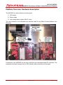
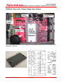
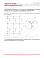
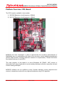
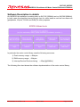
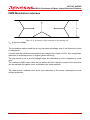
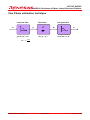
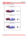
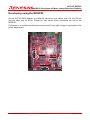
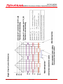
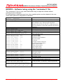
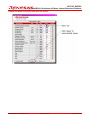
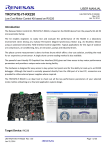
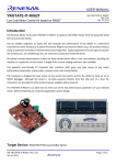
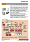
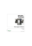
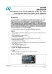
APPLICATION NOTE
SH7125, SH7085
MCRP05: Brushless AC Motor Control Reference Platform
Introduction
This document contains the description of the Motor Control Reference Platform
[MCRP05] based on the powerful 32-bit RISC MCU SH7125 or SH7085. The SH family is
offering unique set of peripherals to drive any motors and is featuring several protection
features for industrial usage.
This platform controls a sensorless 3-phase Brushless Sinusoidal Synchronous motor
inverter by using advanced Field Oriented Control algorithm (FOC).
The motor used is a Brushless motor called also Permanent Magnet motor (PMAC) or
PMSM or BLAC.
The system is in closed loop as the current detection is done via a single shunt (three
shunts is optional) which offers a very low cost solution and avoid any expensive encoder
or current sensor.
The main focus applications are compressors, air conditioning, fans, industrial drives,
washer, etc. The platform is flexible enough to develop any application using Brushless
motor (synchronous & asynchronous).
The main features are:
1) Sensorless
[No need of tachometer or encoder sensors]
2) High Speed
3) High efficiency
[Due to the vector-type motor control]
4) Low noise
alignment]
[Due to the high reachable switching frequency and to the optimal
5) Low Cost
[Due to high integration and to reduced component count]
6) High Reliability
[Due to high integration and to reduced component count]
REG05B0051-0100/Rev.1.00
March 2009
Page 1 of 37
SH7125, SH7085
MCRP05: Brushless AC Motor Control Reference Platform
Content
MCRP05: BRUSHLESS AC MOTOR CONTROL REFERENCE PLATFORM........................................... 1
INTRODUCTION .......................................................................................................................................... 1
CONTENT .................................................................................................................................................... 2
PLATFORM OVERVIEW: HARDWARE DESCRIPTION............................................................................ 3
PLATFORM OVERVIEW: POWER STAGE DESCRIPTION ...................................................................... 4
CURRENT DETECTION METHODS: .......................................................................................................... 6
PLATFORM OVERVIEW: CPU BOARD ..................................................................................................... 7
PERMANENT MAGNET BRUSHLESS MOTOR MODEL .......................................................................... 9
SENSORLESS VECTOR CONTROL ALGORITHM USING SHUNT CURRENT DETECTION............... 15
SOFTWARE DESCRIPTION IN DETAILS ................................................................................................ 16
SPACE VECTORS TRANSFORMATIONS IN DETAILS .......................................................................... 18
PWM MODULATION TECHNIQUE ........................................................................................................... 20
FLUX PHASE ESTIMATION TECHNIQUE ............................................................................................... 21
MCRP05 – PERFORMANCE FIGURES.................................................................................................... 22
DEVELOPING USING THE MCRP05........................................................................................................ 23
MCRP05 SAFETY CONSIDERATIONS .................................................................................................... 24
ENCODER & TACHOMETER INTERFACES ........................................................................................... 25
HALL SENSORS DETECTION.................................................................................................................. 27
SINGLE SHUNT CURRENT DETECTION ................................................................................................ 28
SELECTION BETWEEN SINGLE & THREE SHUNTS............................................................................. 29
MOTOR CABLES COLOURS AND DESCRIPTION................................................................................. 31
MCRP05 – SOFTWARE TUNING USING THE “CUSTOMIZE.H” FILE .................................................. 32
PC INTERFACE – PLATFORM TUNING & MONITORING ...................................................................... 33
WEBSITE AND SUPPORT ........................................................................................................................ 36
REG05B0051-0100/Rev.1.00
March 2009
Page 2 of 37
SH7125, SH7085
MCRP05: Brushless AC Motor Control Reference Platform
Platform Overview: Hardware description
The MCRP05 is mainly divided into three parts:
1) CPU board
2) Power stage
3) Low voltage demo system BLAC motor
The user interface is the standard user interface used for any Motor Control platform from
Renesas.
Furthermore, the MCRP05 can be fully controlled via a dedicated serial PC interface. The
parameters may be changed via the GUI software after connection to the target.
REG05B0051-0100/Rev.1.00
March 2009
Page 3 of 37
SH7125, SH7085
MCRP05: Brushless AC Motor Control Reference Platform
Platform Overview: Power Stage description
The Power stage is based on the Intelligent Power Module called DIP-IPM 20A/600V from
Mitsubishi: PS21065.
The
IPM is
constituted
with six IGBTs
and integrates
the
IGBT
drivers & a
reliable
protection
function:
- For upperarm
IGBTs:
drive
circuit,
high
voltage
isolated highspeed
level
shifting,
low
voltage
REG05B0051-0100/Rev.1.00
March 2009
Page 4 of 37
SH7125, SH7085
MCRP05: Brushless AC Motor Control Reference Platform
detection, short circuit protection (fault signal)
- For lower-arm IGBTs: drive circuit, low voltage detection, short circuit protection (fault
signal)
- Fault signalling: corresponding to a short circuit fault (lower-side IGBT) or low voltage
fault (lower-side IGBT). Such feature is quite appreciated for debug purposes.
- Input interface: 5V line CMOS/TTL compatible, Schmitt trigger circuit.
The IPM is a very reliable solution, low cost with a long life and ensures short dead time
for our application.
The MCRP05 power stage is powered via the external 24V power supply. No rectifier for
higher voltages is available on the board but any rectified voltage up to 400V can be
supplied via the connector X1 of the power board.
For any signals testing an isolated oscilloscope is mandatory to avoid any electrical shocks
when a high voltage is supplied to the power stage.
REG05B0051-0100/Rev.1.00
March 2009
Page 5 of 37
SH7125, SH7085
MCRP05: Brushless AC Motor Control Reference Platform
Current detection methods:
The power stage board is fully working in the following modes:
1) Three Shunts current detection
2) Single Shunt current detection
1) The three shunts configuration allow higher PWM frequency because the influence of
dead time versus PWM period is not significant for the sensorless algorithm.
2) In the three shunts configuration the maximum PWM frequency is the following:
a. Fclock = 80MHz Æ
1/35µs
Æ
FPWM max. = 28.5kHz
b. Fclock = 50MHz Æ
1/56µs
Æ
FPWM max. = 17.8kHz
3) All the previous data are calculated supposing that all the control loops are executed
each PWM period, higher frequency can be reached if control loop frequency is slower
than PWM frequency. In normal industrial application 3KHz control loop frequency is
normally used.
The MCRP05 is offering one alternative: either 3KHz or 10KHz to offer a very high
dynamics to the system.
4) The single shunt configuration forces the designer to reduce the PWM frequency.
a. The PWM frequency must be reduced if the load dynamics is higher.
b. On typical high voltage motors the max. reachable frequency is less than 15kHz.
c. The maximum PWM frequency is reversely proportional to the needed dead-time.
d. The bigger is the dead-time vs. the PWM period the bigger is the “hidden time” that
causes wrong control [wrong alignment between mechanical phase and electrical
phase] in case of high dynamic load.
e. The MCRP05 is offering the choice between 10KHz or 20KHz.
REG05B0051-0100/Rev.1.00
March 2009
Page 6 of 37
SH7125, SH7085
MCRP05: Brushless AC Motor Control Reference Platform
Platform Overview: CPU Board
The CPU board is available in two models:
1) SH7085 [Maximum clock frequency: 80MHz]
2) SH7125 [Maximum clock frequency: 40MHz]
MCRP05 has been developed in order to demonstrate the excellent performances of
SH2/SH2A cores in combination with state of the art motor control dedicated peripherals
(MTU2 PWM module including dead-time insertion & compensation). Please find below
the detailed features of each MCU.
The main purpose of this board is to drive Brushless AC [PMAC, 180°] motors in
sensorless both using single-shunt current reading technique and also using three shunts
current reading technique.
MCRP05 software can be modified to drive 3-phase induction motors (asynchronous
motors) in sensorless mode with very high performances using FOC algorithm.
REG05B0051-0100/Rev.1.00
March 2009
Page 7 of 37
SH7125, SH7085
MCRP05: Brushless AC Motor Control Reference Platform
Please find below the main MCU features:
SH7125
SH7085
Internal clock
50MHz
80MHz
MIPS
65MIPS
110MIPS
MUL timing
20ns
12.5ns
DIV
1.9µs
1.2µs
Saturation Arithmetic
Yes
Yes
Flash
64k / 128k
256k
RAM
8K
16K
External RAM
No, Single Chip
Yes BSC
3 Phase PWM unit
One
Two
PWM fault input
Yes, POE
Yes, POE
MTU2S second PWM
No
Yes
Input capture
19
PWM Resolution (bit @ > 15kHz)
>10
A/D converter resolution
10-bit
> 11 [MTU2]
> 12 [MTU2S]
10-bit
A/D channels
8
12
A/D conversion time
2µs
2µs
A/D module number
2 x S/H modules
3 x S/H modules
A/D sweep mode
Yes
Yes
UART (asynchronous)
3
3
DTC
No
Yes
Code security for On-Chip Flash
Yes
Yes
Watchdog Timer
Yes
Yes
Independent clock for WDT
Yes
Yes
CPU Core
Memory
Peripherals
Communication interfaces
REG05B0051-0100/Rev.1.00
March 2009
Page 8 of 37
SH7125, SH7085
MCRP05: Brushless AC Motor Control Reference Platform
Permanent Magnet Brushless motor model
The synchronous permanent magnets motor (sinusoidal brushless motor) is widely used in
the industry. More & more home appliance makers are now using such brushless motor,
mainly because of the intrinsic motor efficiency.
The permanent magnet motor is made with few components:
1. A stator formed by stacking sheared metal plates where internally the copper wiring
is wound, constructing the stator winding
2. A rotor in which permanent magnets are fixed
3. Two covers with ball bearings that keep together the stator and the rotor; the rotor is
free to rotate inside the stator
“a” winding
“b” winding
ia
Motor axis (shaft)
+
va
vb
“a” winding magnetic axis
ic
ib
+
vc
How current flows into “a” winding
“c” winding
Stator windings schematic
The working principle is quite simple: if we supply the motor with a three-phase system of
sinusoidal voltages, at constant frequency, in the stator windings flows sinusoidal currents,
which create a rotating magnetic field.
The permanent magnets in the rotor tend to stay aligned with the rotating field, so the rotor
rotates at synchronous speed.
The main challenge in driving this type of motor is to know the rotor position in real-time,
so mainly implementation are using a position sensor or a speed sensor.
In our implementation, the system is using either one or three shunts to detect the rotor
position in real-time.
REG05B0051-0100/Rev.1.00
March 2009
Page 9 of 37
+
SH7125, SH7085
MCRP05: Brushless AC Motor Control Reference Platform
Let’s analyse the motor from a mathematic point of view.
If we apply three voltages va(t), vb(t), vc(t) to the stator windings, the relations between
phase voltages and currents are:
dλ a
dt
dλ
vb = RS ib + b
dt
dλ
vc = RS ic + c
dt
va = RS ia +
- λi is the magnetic flux linkage with the i-th stator winding
- RS is the stator phase resistance (the resistance of one of the stator windings)
The magnetic flux linkages λi are composed by two items, one due to the stator currents,
one to the permanent magnets.
The permanent magnet creates a magnetic field that is constant in amplitude and fixed in
position in respect to the rotor.
β axis
c axis
a
α
c’
b’
a axis
c
β’
Λm
ϑ
α axis
β’
b
α’
a’
b axis
Real axes (a, b, c) and equivalent ones (α, β); a fixed amplitude vector can be completely
determined by its position respect the (α, β) system (angle ϑ)
This magnetic field can be represented by vector Λm whose position in respect to the stator
is determined by the angle ϑ between the vector direction and the stator reference frame.
The contribution of the permanent magnets in the flux linkages depends on the relative
position of the rotor and the stator represented by the mechanical-electric angle ϑ.
REG05B0051-0100/Rev.1.00
March 2009
Page 10 of 37
SH7125, SH7085
MCRP05: Brushless AC Motor Control Reference Platform
It is, in every axis, the projection of the constant flux vector Λm in the direction of the axis:
λa = Lia + Λ m cos(ϑ )
λb = Lib + Λ m cos(ϑ − 2π 3 )
λc = Lic + Λ m cos(ϑ − 4π 3 )
Supposing that the rotor is rotating at constant speed ω (that is: ϑ(t) = ωt) the flux linkages
derivatives can be calculated, and we obtain:
dia
− ωΛ m sin(ϑ )
dt
di
vb = RS ib + L b − ωΛ m sin(ϑ − 2π )
3
dt
di
vc = RS ib + L b − ωΛ m sin(ϑ − 4π )
3
dt
v a = RS i a + L
A “three phases system” may be represented by an equivalent “two phases system”. So
the by using specific transformations, our three equations system is equivalent to a two
equations system. It is basically a mathematical representation in a new reference
coordinates system.
In the two phases (α,β) fixed system the above equations become:
vα = RS iα +
vβ = RS iβ +
dλα
dt
dλβ
dt
For the magnetic field equations, we got:
λα = Liα + λαm = Liα + Λ m cos(ϑ )
λβ = Liβ + λβm = Liβ + Λ m sin(ϑ )
After performing derivation:
dλα
di
di
= L α − ωΛ m sin(ϑ ) = L α − ωλβm
dt
dt
dt
diβ
diβ
dλβ
=L
+ ωΛ m cos(ϑ ) = L
+ ωλαm
dt
dt
dt
REG05B0051-0100/Rev.1.00
March 2009
Page 11 of 37
SH7125, SH7085
MCRP05: Brushless AC Motor Control Reference Platform
Finally, we obtain for the voltages in (α,β) system:
diα
− ωλβm
dt
di
vβ = RS iβ + L β + ωλαm
dt
vα = RS iα + L
A second reference frame is used to represent the equations as the frame is turning at the
rotor speed. So the “d” axis is chosen in the direction of the magnetic vector Λm, and with
the “q” axis orthogonal to the “d” axis. The new reference system is (d,q).
The reference frame transformations from the (α,β) system to the (d,q) system depends on
the instantaneous position angle ϑ
So we obtain two inter-dependant equation in the (d,q) system:
did
− ωLiq
dt
diq
vq = RS iq + L
+ ωLid + ωΛ m
dt
vd = RS id + L
These two equations represent the mathematical motor model.
A control algorithm which wants to produce determined currents in the (d, q) system must
impose voltages given from the formulas above.
This is ensured by closed loop PI control on both axis “d” & “q” (Proportional Integral).
Since there is a mutual influence between the two axes, decoupling terms can be used.
In the block scheme, the mechanic part is included, “p” is the number of pole pairs, while
“B” represents friction, “J” the inertia, “τload“ the load torque and “τ” the motor torque.
3
2
τ = × p×Λ
REG05B0051-0100/Rev.1.00
March 2009
Page 12 of 37
SH7125, SH7085
MCRP05: Brushless AC Motor Control Reference Platform
The angular speed ω is represented in the scheme as ωe to distinguish the electrical speed
from the mechanical one.
Vd
1/(R+sL)
+
Id
+
Lωe
Vq
+1/(R+sL)
Iq
pL
(3/2)pΛ
τ
+-
τload
1/(B+sJ)
ωmec
Λωe
pΛ
Let’s now consider the equations we have seen in (α,β) system:
vα = RS iα +
vβ = RS iβ +
dλα
dt
dλβ
dt
These equations show that magnetic flux can be obtained from applied voltages &
measured currents simply by integration:
t
λα = λα 0 + ∫ (vα −RS iα )dt
0
t
λβ = λβ 0 + ∫ (vβ −RS iβ )dt
0
Furthermore:
Λ m cos(ϑ ) = λα − Liα
Λ m sin(ϑ ) = λβ − Liβ
REG05B0051-0100/Rev.1.00
March 2009
Page 13 of 37
SH7125, SH7085
MCRP05: Brushless AC Motor Control Reference Platform
As the phase inductance L is normally small, we can neglect the inductance contribution in
the equation. So we get:
λα = Λ m cos(ϑ )
λβ = Λ m sin(ϑ )
So in the (α,β) system phase we obtain from the flux components:
λ
ϑ = arctan( β λ )
α
The system speed ω can also be deduced from the derivative of the angle ϑ.
Based on this, a sensorless control algorithm was developed to give the imposed phase
voltages, to measure phase currents, to estimate the angular position ϑ and finally the
system speed:
⎛d ⎞
w =⎜ ϑ⎟
⎝ dt ⎠
REG05B0051-0100/Rev.1.00
March 2009
Page 14 of 37
The only different between the three shunts and the single shunt configurations is in the “Current Detection” block, the rest of
the algorithm remains the same.
Please, find below the FOC sensorless algorithm block diagram.
Sensorless vector control algorithm using shunt current detection
SH7125, SH7085
MCRP05: Brushless AC Motor Control Reference Platform
Sensorless vector control algorithm using shunt current detection
REG05B0051-0100/Rev.1.00
March 2009
Page 15 of 37
SH7125, SH7085
MCRP05: Brushless AC Motor Control Reference Platform
Software Description in details
On MCRP05 this software is working both on SH7125 [50MHz] and on SH7085 [80MHz],
in both cases the algorithm leaves enough time for other tasks as well as free resources
[peripherals, I/O pins, FLASH and RAM] for other purposes.
In particular the motor control library uses the following resources:
1) Flash memory usage: < 8Kbytes
2) RAM memory usage: ~1Kbytes
3) Interrupt Service Routines timing:
< 35µs [@ 80MHz]
The following flow chart shows the software implementation of the motor control library.
REG05B0051-0100/Rev.1.00
March 2009
Page 16 of 37
SH7125, SH7085
MCRP05: Brushless AC Motor Control Reference Platform
Interrupt occours at through of pwm generation (timer4 underflow)
Single-Shunt A/D conversions results reading
New phase setting
Normal A/D conversion (vbus etc.) start
"d" axe current PI produces "d" axe voltage set
"q" axe current PI produces "q" axe voltage set
While waiting for A/D end,
scaling of single shunt conversions
Voltages anti-transformations
(d, q)->(a, b)->(u, v, w)
Scaling normal A/D conversions results
No
Modulation
(u, v, w)voltages->(u, v, w)duties
Motor energized?
Yes
Single shunt A/D conversions setting
Estimators reset
Current transformations
(u, v, w)->(a, b)->(d,q)
Flux phase extimation
Speed extimation
Startup?
Yes
No
Speed PI produces Iq reference
Startup procedure
End of main interrupt
REG05B0051-0100/Rev.1.00
March 2009
Page 17 of 37
SH7125, SH7085
MCRP05: Brushless AC Motor Control Reference Platform
Space vectors transformations in details
Find below the detailed equations used for the coordinates transformations.
2
1
1
(ga − gb − gc ) = ga
3
2
2
2 3
3
1
1
gβ = (
gb −
gc ) =
(gb − gc ) =
(g a + 2gb )
3 2
2
3
3
gα =
(a, b, c) → (α, β)
g a = gα
1
3
g b = − gα +
g β = (− g a + 3g b ) / 2
2
2
1
3
g c = − gα −
g β = (− g a − 3g b ) / 2
2
2
(α, β) → (a, b, c)
g d = g α cos(ϑ ) + g β sin(ϑ )
g q = − g α sin(ϑ ) + g β cos(ϑ )
(α, β) → (d, q)
gα = g d cos(ϑ ) − g q sin(ϑ )
g β = g d sin(ϑ ) + g q cos(ϑ )
(d, q) → (α, β)
2
g d = ( g a cos(ϑ ) + g b cos(ϑ − 2π / 3) + g c cos(ϑ − 4π / 3))
3
2
g q = − ( g a sin(ϑ ) + g b sin(ϑ − 2π / 3) + g c sin(ϑ − 4π / 3))
3
(a, b, c) → (d, q)
g a = g d cos(ϑ ) − g q sin(ϑ )
g b = g d cos(ϑ − 2π / 3) − g q sin(ϑ − 2π / 3)
g c = g d cos(ϑ − 4π / 3) − g q sin(ϑ − 4π / 3)
potenzad ,q = potenzaα ,β =
(d, q) → (a, b, c)
2
potenzaa ,b ,c
3
REG05B0051-0100/Rev.1.00
March 2009
Page 18 of 37
SH7125, SH7085
MCRP05: Brushless AC Motor Control Reference Platform
u a = U cos(ωt + ϕ 0 )
ub = U cos(ωt + ϕ 0 − 2π / 3)
uα = U cos(ωt + ϕ 0 )
u c = U cos(ωt + ϕ 0 − 4π / 3) ↔
u β = U sin(ωt + ϕ 0 )
REG05B0051-0100/Rev.1.00
March 2009
u d = U cos(ϕ 0 )
↔
u q = U sin(ϕ 0 )
(ϑ=ωt)
Page 19 of 37
SH7125, SH7085
MCRP05: Brushless AC Motor Control Reference Platform
PWM Modulation technique
VDC
Figure X.X: geometrical representation of the rotating star
VDC is the bus voltage.
The modulation method used has a very important advantage: one of the three duty cycles
is always zero.
It means that the switches commutations are reduced by a factor of 30%, with a significant
reduction of switching losses, so higher system efficiency.
The star-centre is not at a fixed voltage value, but describes a curve composed by circle
arcs.
The maximum RMS output value we can obtain with this method is equal to the value that
can be reached with space vector modulation and other methods.
The other known methods don't allow such reduction of the power consumption at low
voltage amplitude.
REG05B0051-0100/Rev.1.00
March 2009
Page 20 of 37
SH7125, SH7085
MCRP05: Brushless AC Motor Control Reference Platform
Flux Phase estimation technique
Low pass filter
xn
Derivation
yn
yn= K x yn-1 + xn
with K =
d
dt
dn= yn - yn-4
Low pass filter
dn
zn
zn= K x zn-1 + dn
1023
1024
REG05B0051-0100/Rev.1.00
March 2009
Page 21 of 37
SH7125, SH7085
MCRP05: Brushless AC Motor Control Reference Platform
MCRP05 – Performance figures
SH7085 @ 80MHz
Switching Frequency: 10KHz
35%
CPU usage
Free resources
65%
SH7085 @ 80MHz
Sw itching Frequency: 16KHz
40%
CPU usage
Free resources
60%
SH7085 @ 80MHz
Sw itching Frequency: 20KHz
25%
CPU usage
Free resources
75%
REG05B0051-0100/Rev.1.00
March 2009
Page 22 of 37
SH7125, SH7085
MCRP05: Brushless AC Motor Control Reference Platform
Developing using the MCRP05
On the SH7125 MCU boards, two different connectors are visible: one if for the E8 tool
and the other one for E10A. Please be very careful when connected the tool to the
MCRP05.
Furthermore, an isolated oscilloscope must be used if any high voltage is connected to the
power stage board.
E8
Reset
E10A
Serial U/I
RS232
REG05B0051-0100/Rev.1.00
March 2009
Page 23 of 37
SH7125, SH7085
MCRP05: Brushless AC Motor Control Reference Platform
MCRP05 Safety considerations
MCRP05 is designed as a demonstration and development set. The case is delivered with
a compact external power supply providing low voltages (5V, 15V, 23V).
The DC Bus voltage is 23V to guarantee any electric shock during demonstration.
The use of no other external energy sources guarantees that no electrical shocks are
possible when using MCRP05 with E10A emulator or with a PC connected.
Any other possible use is not supported and should be avoided.
The X1 connector of the power stage is connected to the DC power Bus. It is provided only
for test purposes to connect any other specific motors and any other DC bus voltage.
Please be aware that the power bus reference (-VBUS) is directly connected to the MCU
board ground. By using the E10A emulator, it is connected directly with the PC ground.
It’s strongly recommended to use a transformer to insulate the board from the PC when it’s
connected to the RS232.
The RS232 interface is electrically insulated (opto-coupled) from the rest of the demo set,
but for safety purposes it must be considered NOT insulated.
REG05B0051-0100/Rev.1.00
March 2009
Page 24 of 37
SH7125, SH7085
MCRP05: Brushless AC Motor Control Reference Platform
Encoder & tachometer interfaces
For the development of the platform, an encoder and current transducers (LEM) were used.
That’s why it is possible to connect any five-wires encoder to the platform and adapt the
software source code to enable the function.
A quadrature encoder can be used to detect the motor speed. It can be connected to the
X4 connector, as indicated in the figure.
The pin out is:
1) Encoder Ground
2) Encoder A
3) Encoder B
4) Encoder 0 (if the encoder uses a zero signal)
5) Encoder Positive supply (+5V)
1
X 4 C O N N .
In the MCRP05 software some routines for encoder reading are already done and can be
found in “motorcontrol.c” file. They are:
•
void McrpLib_StartEnc(void): timer 1 settings (phase counting mode 1) for
encoder input reading, timer start.
•
void McrpLib_ReadEnc(void): encoder reading.
In the same file “motorcontrol.c” can be found also some macros to define encoder type.
REG05B0051-0100/Rev.1.00
March 2009
Page 25 of 37
SH7125, SH7085
MCRP05: Brushless AC Motor Control Reference Platform
- The default setting is for a 4096 pulses/revolution encoder (1024 teeth).
- The reading of the encoder pulses is performed by the hardware peripheral of the
microcontroller.
- The software routine samples the result and applies the filters and the conversions.
Please refer to the microcontroller manual for further details.
The hardware interface to connect a tachometer reading is also provided, using connector
X2.
Please have a look at the figure below: the connector X2 is a two pins connector between
the connect X1 (three pins) and X4 (five pins).
No software interface is actually provided.
REG05B0051-0100/Rev.1.00
March 2009
Page 26 of 37
SH7125, SH7085
MCRP05: Brushless AC Motor Control Reference Platform
Hall sensors detection
The connector X3 and the switches S3 can be used to select the detection of hall sensors
signals for BLDC motor control.
The software is not provided yet. Switches S3 can also be used to select HW commutation
signals from power stage, for dead time compensation. Please refer to the hardware
drawings for more details.
The S3 DIP-switch is used to select between thee options: a fully sensorless option (by
default), a sensorless using back-EMF approach where the back-EMF signals are
connected to the MCU and finally the Hall sensors approach connected directly to the
MCU.
ON
Fully sensorless
Default configuration
X 3 C ON N.
S3 S W IT C H E S
ON
Sensorless Back-EMF
signals enable
OFF 1 2 3 4 5 6 7 8
S3 Switch
CPU board
Hall sensors inputs
enable
REG05B0051-0100/Rev.1.00
OFF 1 2 3 4 5 6 7 8
S3 Switch
CPU board
March 2009
ON
OFF 1 2 3 4 5 6 7 8
S3 Switch
CPU board
Page 27 of 37
SH7125, SH7085
MCRP05: Brushless AC Motor Control Reference Platform
Single Shunt Current Detection
Single Shunt Current Detection
REG05B0051-0100/Rev.1.00
March 2009
Page 28 of 37
SH7125, SH7085
MCRP05: Brushless AC Motor Control Reference Platform
Selection between Single & three shunts
In order to change between single shunts to three shunts, there are two operations to
make:
1) On the back side of the power stage, two soldering points are use to enable of
disable the three shunts or single shunt current detection (see below the figure)
2) On the software side in the “customize.h” file, please enable of disable the
following switches:
//#define
SINGLESHUNT
#define
THREESHUNTS
Only one of the “define” should remain commented
Back side of the power stage board
Three shunts
configuration
X
Y
Z
[
Sold Z& [
Leave open X & Y
REG05B0051-0100/Rev.1.00
March 2009
Single shunt
configuration
X
Y
Z
[
Sold X & Y
Leave open Z& [
Page 29 of 37
SH7125, SH7085
MCRP05: Brushless AC Motor Control Reference Platform
PWM switching frequency and timings
The PWM switching frequency can be adjusted by the user using the macro PWM_FRE in
the file called “customize.h” to fulfil the application requirements.
Two possible frequencies are selectable:
1) 10kHz: higher noise but higher efficiency
2) 20kHz: less noise & better sin wave shape
The algorithm sampling period is fixed to 100µs (10KHz) and the main interrupt is related
with the PWM frequency.
Thanks to the interrupt skipping facility of the MTU2 peripheral, it becomes easy to adjust
the application software to 10KHz or 20KHz.
Other PWM switching frequency values can be obtained by directly modifying the macro
called SEMIPER (half PWM period in MTU2 clock cycles units), but it is not recommended
as the overall algorithm behaviour is affected.
The timing of the main program is regulated by the macro NUM_INT in “motorcontrol.c” file.
The value of NUM_INT regulates the number of interrupts in the main loop. Such macro
can be adjusted but it will affect all the timings of the routines called in main program.
REG05B0051-0100/Rev.1.00
March 2009
Page 30 of 37
SH7125, SH7085
MCRP05: Brushless AC Motor Control Reference Platform
Motor cables colours and description
•
U Phase (power)
WHITE/RED
•
V Phase (power)
WHITE /YELLOW
•
W Phase (power)
WHITE /BLACK
0
•
Hall A (U)
A (U)
•
B (V)
WHITE
(gives the sign of V-W back-EMF)
•
Hall C (W)
120
180
240
300
360
GREEN
(gives the sign of U-V back-EMF)
Hall B (V)
60
BLUE
C (W)
U-V
(gives the sign of W-U back-EMF)
•
Hall GND
BLACK
•
Hall +VCC
RED
V-W
W-U
REG05B0051-0100/Rev.1.00
March 2009
Page 31 of 37
SH7125, SH7085
MCRP05: Brushless AC Motor Control Reference Platform
MCRP05 – Software tuning using the “customize.h” file
The “customize-h” file is a very useful and flexible way to adapt the software without
entering into the code itself.
By commenting or modifying some lines, the complete system can be adapted to the user
needs and is perfect for any platform evaluation.
Select one shunt or three shunts for current detection
#define
SINGLESHUNT
//#define
THREESHUNTS
#define PWM_FREQ_CUSTOM 20000
PWM frequency modulation: between 3KHz and 20KHz
Selects sign of the current read through the shunt and the
related amplifier stage. When using the MCRP05
schematics this line must be left as it is. When the positive
input of the OpAmp is connected to GND this line must be
commented.
Enable the use of the external E²PROM
Enable display usage
Enable SCIO for external connection
Control loop time in Hz between 2500Hz up to 10KHz
Startup ramp time in ms
min speed in RPM
max speed in RPM
acceleration ramp in RPM/sec
polar pairs number
flux current
max torque current in Arms/10
stator phase resistance in Ω/10
K prop. current control
K integ. current control
K prop. speed control
K integ. speed control
#define POSCURR
#define EEPROM_USED
#define DISPLAY_USED
#define MCRP05_SCI0_CONNECTION
#define SAMPLE_FREQ_CUSTOM
10000
#define STARTUP_RAMPTIME_CUSTOM 800
#define
#define
#define
#define
#define
#define
#define
#define
#define
#define
#define
#define
RPM_MIN_CUSTOM
RPM_MAX_CUSTOM
R_ACC_CUSTOM
C_POLI_CUSTOM
ID_NOM_CUSTOM
IQ_NOM_CUSTOM
R_STA_CUSTOM
KP_CUR_CUSTOM
KI_CUR_CUSTOM
KP_VEL_CUSTOM
KI_VEL_CUSTOM
DEADTIM_CUSTOM
600
4500
1000
2
0
30
7
150
100
30
20
2.0
#define RSHUNT_CUSTOM
#define RSGAIN_CUSTOM
#define AVCC_CUSTOM
100.0
5000.0
5000.0
#define RVBUS1_CUSTOM
#define RVBUS2_CUSTOM
400000.0
4700.0
#define VIGBTV_CUSTOM
#define VDIODOV_CUSTOM
800.0
1400.0
#define
#define
#define
#define
#define
#define
FIRST_FLUX_LOWPASS_TIME_CUSTOM 10
DERIVATIVE_TIME_CUSTOM 1
LAST_FLUX_LOWPASS_TIME_CUSTOM 10
FIRST_SPEED_LOWPASS_TIME_CUSTOM 5
SECOND_SPEED_LOWPASS_TIME_CUSTOM 4
THIRD_SPEED_LOWPASS_TIME_CUSTOM 3
REG05B0051-0100/Rev.1.00
Dead-time value in µs @40MHz
Shunt value in mΩ
Circuit gain x1000
A/D Range in mV
Split resistor 1 in Ω
Split resistor 2 in Ω
VCESAT of the IGBT in mV
Free-wheel diode forward voltage in mV
Flux phase estimation is made through following steps: 1)
first low pass filter, 2) derivative, 3) last low pass filter
Filters parameters
March 2009
Page 32 of 37
SH7125, SH7085
MCRP05: Brushless AC Motor Control Reference Platform
PC Interface – Platform tuning & monitoring
A complete PC based interface is available to display the main values & measurements
like the motor speed, the motor currents, the torque, the DC Bus voltage, etc.
Please find below the screen shot of the PC interface connected via RS232 link to the
MCRP05.
By selection the label on the right hand side, the graph will automatically display the realtime values, so it becomes easy to analyse the influence of the motor load on the motor
speed.
The range of the graph can be easily modified by clicking the button “Range”:
As soon as reference speed is set, whatever the torque required the system will keep a
very accurate speed showing a fast reaction time and good system dynamics.
REG05B0051-0100/Rev.1.00
March 2009
Page 33 of 37
SH7125, SH7085
MCRP05: Brushless AC Motor Control Reference Platform
Furthermore, the software running on the platform is using system parameters that may be
modified via the PC user interface.
In the main menu, it is possible to display the platform parameters & modify them.
Please find above the default values for each parameter. Note that that some coefficients
with “0” as values are not used like “the speed loop KD”.
The stator resistance is a key parameter that needs to be adapted to each motor type.
After changing the value, please click on “Apply” and perform a board reset to start the
system with the new parameters.
If any issues are happening during the programming of the board or during the parameters
modification, a simple way is to write the magic value “33” in the first line: “Default
Parameters Setting”.
REG05B0051-0100/Rev.1.00
March 2009
Page 34 of 37
SH7125, SH7085
MCRP05: Brushless AC Motor Control Reference Platform
Please find below the screen shot with the details.
REG05B0051-0100/Rev.1.00
March 2009
Page 35 of 37
SH7125, SH7085
MCRP05: Brushless AC Motor Control Reference Platform
Website and Support
Renesas Technology Website
http://www.renesas.com/
Inquiries
http://www.renesas.com/inquiry
[email protected]
All trademarks and registered trademarks are the property of their respective owners.
REG05B0051-0100/Rev.1.00
March 2009
Page 36 of 37
SH7125, SH7085
MCRP05: Brushless AC Motor Control Reference Platform
Notes regarding these materials
1.
2.
3.
4.
5.
6.
7.
8.
9.
10.
11.
12.
13.
This document is provided for reference purposes only so that Renesas customers may select the appropriate
Renesas products for their use. Renesas neither makes warranties or representations with respect to the
accuracy or completeness of the information contained in this document nor grants any license to any intellectual
property rights or any other rights of Renesas or any third party with respect to the information in this document.
Renesas shall have no liability for damages or infringement of any intellectual property or other rights arising out
of the use of any information in this document, including, but not limited to, product data, diagrams, charts,
programs, algorithms, and application circuit examples.
You should not use the products or the technology described in this document for the purpose of military
applications such as the development of weapons of mass destruction or for the purpose of any other military
use. When exporting the products or technology described herein, you should follow the applicable export
control laws and regulations, and procedures required by such laws and regulations.
All information included in this document such as product data, diagrams, charts, programs, algorithms, and
application circuit examples, is current as of the date this document is issued. Such information, however, is
subject to change without any prior notice. Before purchasing or using any Renesas products listed in this
document, please confirm the latest product information with a Renesas sales office. Also, please pay regular
and careful attention to additional and different information to be disclosed by Renesas such as that disclosed
through our website. (http://www.renesas.com)
Renesas has used reasonable care in compiling the information included in this document, but Renesas
assumes no liability whatsoever for any damages incurred as a result of errors or omissions in the information
included in this document.
When using or otherwise relying on the information in this document, you should evaluate the information in light
of the total system before deciding about the applicability of such information to the intended application.
Renesas makes no representations, warranties or guaranties regarding the suitability of its products for any
particular application and specifically disclaims any liability arising out of the application and use of the
information in this document or Renesas products.
With the exception of products specified by Renesas as suitable for automobile applications, Renesas products
are not designed, manufactured or tested for applications or otherwise in systems the failure or malfunction of
which may cause a direct threat to human life or create a risk of human injury or which require especially high
quality and reliability such as safety systems, or equipment or systems for transportation and traffic, healthcare,
combustion control, aerospace and aeronautics, nuclear power, or undersea communication transmission. If you
are considering the use of our products for such purposes, please contact a Renesas sales office beforehand.
Renesas shall have no liability for damages arising out of the uses set forth above.
Notwithstanding the preceding paragraph, you should not use Renesas products for the purposes listed below:
(1) artificial life support devices or systems
(2) surgical implantations
(3) healthcare intervention (e.g., excision, administration of medication, etc.)
(4) any other purposes that pose a direct threat to human life
Renesas shall have no liability for damages arising out of the uses set forth in the above and purchasers who
elect to use Renesas products in any of the foregoing applications shall indemnify and hold harmless Renesas
Technology Corp., its affiliated companies and their officers, directors, and employees against any and all
damages arising out of such applications.
You should use the products described herein within the range specified by Renesas, especially with respect to
the maximum rating, operating supply voltage range, movement power voltage range, heat radiation
characteristics, installation and other product characteristics. Renesas shall have no liability for malfunctions or
damages arising out of the use of Renesas products beyond such specified ranges.
Although Renesas endeavors to improve the quality and reliability of its products, IC products have specific
characteristics such as the occurrence of failure at a certain rate and malfunctions under certain use conditions.
Please be sure to implement safety measures to guard against the possibility of physical injury, and injury or
damage caused by fire in the event of the failure of a Renesas product, such as safety design for hardware and
software including but not limited to redundancy, fire control and malfunction prevention, appropriate treatment
for aging degradation or any other applicable measures. Among others, since the evaluation of microcomputer
software alone is very difficult, please evaluate the safety of the final products or system manufactured by you.
In case Renesas products listed in this document are detached from the products to which the Renesas products
are attached or affixed, the risk of accident such as swallowing by infants and small children is very high. You
should implement safety measures so that Renesas products may not be easily detached from your products.
Renesas shall have no liability for damages arising out of such detachment.
This document may not be reproduced or duplicated, in any form, in whole or in part, without prior written
approval from Renesas.
Please contact a Renesas sales office if you have any questions regarding the information contained in this
document, Renesas semiconductor products, or if you have any other inquiries.
© 2009. Renesas Technology Corp., All rights reserved.
REG05B0051-0100/Rev.1.00
March 2009
Page 37 of 37