1
PRO SERIES
USER MANUAL
FOR THE
PS 150
SINGLE CHANNEL TELEPHONE INTERFACE
CONTENTS
1.0
2.0
3.0
4.0
5.0
6.0
7.0
8.0
9.0
GENERAL DESCRIPTION . . . . . . . . . . . . . . . . . . . . . .
UNPACKING . . . . . . . . . . . . . . . . . . . . . . . . . . . . . . . . .
INSTALLATION . . . . . . . . . . . . . . . . . . . . . . . . . . . . . . .
FRONT PANEL CONTROLS . . . . . . . . . . . . . . . . . . . . .
REAR PANEL CONNECTORS . . . . . . . . . . . . . . . . . . .
CABLING . . . . . . . . . . . . . . . . . . . . . . . . . . . . . . . . . . . .
PARTY LINE, TECHNICAL CONCEPT . . . . . . . . . . . . .
GUARANTEE . . . . . . . . . . . . . . . . . . . . . . . . . . . . . . . . .
TECHNICAL SPECIFICATIONS . . . . . . . . . . . . . . . . . .
User Manual PS 150 / Issue 1 © 1994 ASL Intercom, Utrecht, Holland.
3
3
3
4
5
6
7
7
7
2
User Manual PS 150 / Issue 1 © 1994 ASL Intercom, Utrecht, Holland.
1.0
GENERAL DESCRIPTION
The PS 150 is designed to interface the ASL intercom
system (3-wire, party line) to the telephone system
(2-wire).
For example communication can be realised between a
normal telephone and one or more ASL stations, or
between two ASL systems via a telephone-line.
The PS 150 is a sub-station and receives power from the
intercom line.
The PS 150 is a combination of two interfaces.
One for interfacing the intercom line to a separate input
and output, and one for interfacing the telephone line to a
separate input and output.
These inputs and outputs are internally (cross-) connected.
The two-stage sidetone circuit (level, hi) allows you to
obtain an input/output separation better than 30 dB from
20Hz to 20KHz.
The built in testtone generator helps you to adjust or check
the sidetone level at any time.
2.0
UNPACKING
The shipping carton contains the parts listed below
* The PS 150
* Set of telephone cables
* User manual
If any are missing, contact your dealer.
ASL has taken great care to ensure this product reaches
you in flawless condition.
After unpacking the unit please inspect for any physical
damage to the unit, and retain the shipping carton and
relevant packing materials for use should the unit need
returning.
If any damage has occurred, please notify your dealer so
that a written claim can be initiated. Please also refer to the
guarantee section of this manual.
3.0
MECHANICAL INSTALLATION
The PS 150 will interface between ASL partyline (3-wire
intercom) and 2-wire telephone systems.
To connect the PS 150 with ASL partyline system, use
professional flexible microphone cable with 2 wires and 1
shield only. Connect the partyline system cable into the
intercom line connector on the rear.
To connect the PS 150 with the 2-wire telephone system,
use the telephone cable to the FCC type connector on the
rear.
There are no separate power connections to install since
the necessary DC voltages are derived from the ASL
partyline.
The PS 150 is fully protected against mis-wiring (reverse
power) or short circuit in the interconnecting cables.
User Manual PS 150 / Issue 1 © 1994 ASL Intercom, Utrecht, Holland.
If your telephone system does not use the FCC type
connectors we have applied on the PS 150 you can use
these extra cables for interconnecting.
Connection procedure :
1. Lift the covers of the telephone line connector and the
telephone plug, which your system applies.
2. Use their connection screws for attaching the four
leads coming from each cable following these colour
assignments:
yellow
EB
green
b
red
a
black
ground
3. Put the covers back in place.
3
4.0
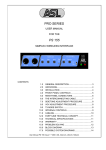
FRONT PANEL CONTROLS
The PS 150 is a combination of two interfaces.
One for interfacing the intercomline to a separate input and
output, and one for interfacing the telephone line to a
separate input and output.
These inputs and outputs are internally cross connected.
Both interfaces have their own sidetone trimmers.
The two sidetone trimmers at the left side of the front panel
control the internal input/output separation of the intercom
line interface.
The sidetone trimmer in the right of the front panel controls
the internal input/output separation of the telephone line
interface.
For prevention of internal feedback or a 'hollow sound' in
both systems all sidetone trimmers must be adjusted carefully.
1
SIDETONE LEVEL trimmer (INTERCOM LINE)
This trimmer controls the internal input/output
separation of the intercom line interface.
It also compensates the resistance of the
interconnecting cables.
For sidetone adjustment procedure see 4.4.
2
SIDETONE HI trimmer
This trimmer controls the internal input/output
separation in the high-frequency range.
It compensates the capacity of the interconnecting
cables.
3
SIDETONE TEST knob
This hidden pushbutton switch activates a testtone
generator which adds a 200Hz tone to the internal
input signal of the intercom line interface.
It allows you to adjust or check the sidetone trimmer
settings of the intercom line interface.
Note: Make sure you are not disturbing any
communication because the test-tone is placed on the
intercomline which implies that all stations on that
channel can hear the test tone.
4
4
SIDETONE LEVEL trimmer (TELEPHONE LINE)
This trimmer controls the internal input/output
separation of the telephone line interface.
The telephone line sidetone rejection may be rather poor
compared to the intercomline sidetone rejection because
of the complex impedance of the telephone line.
Because the PS 150 combines two interfaces, a decrease
of sidetone rejection in all intercom stations connected to
the same channel as the PS 150 might occur.
If speaker stations are connected, internal feedback may
occur.
If this problem arises, it can be solved by keeping the send
and receive levels of the PS 150 low and by turning the
speaker attenuator trimmers of the howling speaker
station(s) anti clockwise.
SIDETONE ADJUSTMENT PROCEDURE
- plug a headset in the test headset connector.
- set receive level to minimum.
set send level to maximum.
- set intercom line sidetone trimmers in start position :
level : turn fully clockwise.
hi
: turn fully anti-clockwise.
- activate the testtone generator.
- decrease testtone level by turning the level trimmer
anti-clockwise.
adjust for minimum level.
- decrease the remaining high-frequencies by turning the
hi trimmer clockwise.
- repeat the last three steps until you are sure you have
obtained the best possible settings.
- set telephone line sidetone trimmer in start position:
turn level trimmer fully clockwise.
- connect an ASL sub-station (beltpack, speaker station)
to the intercom channel and adjust its sidetone for
minimal level.
- connect the PS 150 to the telephone line and make
connection with the front panel connect switch.
- Turn up receive level slowly while speaking into the
headset mike. The volume of your voice will increase.
- Turn telephone line sidetone level trimmer anticlockwise and adjust for minimum level.
User Manual PS 150 / Issue 1 © 1994 ASL Intercom, Utrecht, Holland.
4.0
5
6
FRONT PANEL CONTROLS
TEST HEADSET connector
This connector allows you to listen to the intercom line
during the sidetone adjustment procedure (see 4.4 ), or
continuously.
You can plug in a headset or headphones.
Pin assignment :
1. not connected
2. not connected
3. phones +
4. phones (GND)
CONNECT switch
This switch connects the telephone line to either the
telephone or to the telephone interface.
If you switch the telephone line to the PS 150, the hold
indicator illuminates.
If you have switched the telephone line from the
telephone to the PS 150, you may place the telephone
handset back on the hook, because the PS 150 will
hold the connection.
5.0
7
HOLD indicator led
This led illuminates if you have switched the telephone
line to the PS 150.
It indicates that the telephone line is occupied (by the
PS 150).
8
RECEIVE volume control knob
This knob controls the listen level of the telephone line
signal as it is received by the intercomline.
9
SEND volume control knob
This knob controls the listen level of the intercom line
signal as it is send to the telephone line.
10 POWER INDICATOR
This LED illuminates if line power is supplied by the
power supply or master station of the ASL intercom
system in which the PS 150 is used.
REAR PANEL CONTROLS
At the rear panel you will find the connectors for inter
connecting the PS 150 within the ASL intercom system
and within the telephone system.
The telephone line connection is transformer balanced.
12 INTERCOM IN connector
This XLR-3 is for connecting the intercomline.
Pin assignments :
1. 0V / ground shield
2. + 30V power wire
3. audio wire
13 INTERCOM LINK connector
This output is for extending the intercom line to other
sub-stations.
It is linked to the intercom line input connector and has
the same pin assignments.
User Manual PS 150 / Issue 1 © 1994 ASL Intercom, Utrecht, Holland.
14 TELEPHONE LINE connector
This connector is for connecting the telephone line.
Pin assignments :
1 not connected
2 EB
3 b
4 a
5 ground
6 not connected
The pin 3 and 4 of the telephone line connector are
switched to pins 3 and 4 of the telephone connector
when the PS 150 is off-line (HOLD led is off), and
switched to the interface when the PS 150 is on-line
(HOLD led is lit).
15 TELEPHONE connector
This connector is for connecting a telephone, a
telephone bell or any other telephone apparatus.
Pin assignments : see 14.
The pins 2 and 5 of the telephone connector are
always interconnected with pin 2 and 5 of the line
connector.
5
7.0
CABLING
For the PRO Series Intercom system the interconnecting
cables are of the shielded two-conductor microphone
cable type and the intercom line connectors are of the
XLR-3 type. Audio and Call signals are on XLR pin 3, DC
power is on XLR pin 2. XLR pin 1 is connected to the
shield of the cable which functions as the common return
for audio and power.
¼
Since the audio signal is transferred in an unbalanced
way, certain rules have to be obeyed when installing the
cables of an intercom network. This is to avoid earth loops
and to minimize power loss and the possible effect of
electromagnetic fields.
These rules are:
Use high quality (multipair) cable.
For interconnecting user stations, power supplies and
accessories in an ASL Intercom network, use high
quality shielded two-conductor (minimum 2x 0.30 mm2)
microphone cable only.
In case of a multi channel intercom network, use high
quality microphone 'multipair' cable only, each pair
consisting of two conductors (minimum 2x 0.15 mm2)
with separate shield. Multipair cable should also have
an overall shield.
Use flexible cables.
Use flexible single and multipair microphone cable
instead of cable with solid cores, especially when the
cable is subjected to bending during operation or
installation.
Separate cable screen to XLR pin 1.
The screen of each separate microphone cable and/or
the screen of each single pair in a multipair cable,
should be connected to pin 1 of each XLR-3 connector.
Do not connect this cable screen to the metal housing
of the connector or to metal wall boxes (outlets).
See page 10 for Earthing Concept.
Cable trunks, connection boxes and overall
multipair cable screen to clean earth.
Metal cable trunks, metal connection boxes and overall
multipair cable screen should be interconnected and,
at one point (the 'central earthing point') in the intercom
network only, be connected to a clean safety earth.
See page 10 for Earthing Concept.
Keep metal connection boxes and cable trunks
isolated from other metal parts.
Metal housings for intercom cables and connectors
should be mounted in such a way that they are isolated
from other metal cable and connector housings and
from any other metal construction parts.
¼ See Party Line, Technical Concept
6
Keep cables parallel as much as possible
When two (multi channel) units in a network are
connected by more than one cable, make sure that
these cables are parallel to each other over the whole
distance between those units. When using multipair
cable, parallelism is ensured in the best possible way.
Avoid closed loops.
Always avoid that cables are making a loop. So-called
'ring intercom' should not physically be cabled as a
ring. All cable routes should have a 'star' configuration,
with the central earthing point (usually close to the
power supply position) as the centre of the star.
Keep cables away from electromagnetic sources.
Keep intercom cables away from high energy cables,
e.g. 110/220/380V mains power or dimmer controlled
feeds for spotlights.
Intercom cables should cross high energy cables at an
angle of 90( only.
Intercom cables should never be in the same trunking
as energy cables.
Place power supplies in a central position.
In order to avoid unacceptable power losses, place the
power supplies as close as possible to where most
power consumption occurs or, in other words, most
user stations are placed.
Connect ASL power supply to a 'clean' mains
outlet.
The ASL power supply may be connected to the mains
power outlet to which other audio equipment is
connected. Avoid using mains outlets which also power
dimmer controlled lighting systems.
In case of more complex installations, don't hesitate to
contact us. Please send us a block diagram of the
planned network with a list of all user stations and their
positions, and we are happy to advise you on cabling
lay-out.
User Manual PS 150 / Issue 1 © 1994 ASL Intercom, Utrecht, Holland.
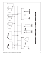
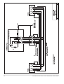
8.0
PARTY LINE, TECHNICAL CONCEPT
ASL's PRO Series offers a complete two way ('full duplex')
communications system.
Users of the system are connected via a 'party line'.
Master stations (with built-in power supply), beltpacks,
speaker stations and power supplies are interconnected
via standard microphone cable. One wire is used as an
audio line, one as a power line and the screen of the cable
functions as earth/return.
Current drive is used for signal transfer. Each station
utilises a current amplifier to amplify the microphone signal
and place it on the common audio line where, due to the
constant line impedance (situated in the power supply
between XLR pin 3 and 1), a signal voltage is developed
which can be further amplified and sent to headphones or
loudspeakers.
This principle has three advantages:
- the use of a single audio line allows several stations to
talk and listen simultaneously.
- due to the high bridging impedance offered by each
station, the number of stations 'on line' has no
influence on the level of the communications signal.
- power and audio to the intercom stations use the same
cable.
The Call signal is also sent as a current on the audio line.
It develops a DC potential over the line impedance which
will be sensed by each station and interpreted as a Call
signal.
10.0 TECHNICAL SPECIFICATIONS PS 150
INTERCOM LINE DRIVER
Max. output current
output impedance
3mA rms
> 150 kOhm
INTERCOM LINE SIDETONE
rejection
cable compensation
> 34 dB (20 Hz - 20 kHz)
0 - 1000 meters
TELEPHONE LINE DRIVER
output impedance
max. output
freq.response
600 Ohms
+14 to -34 dBm
150 Hz - 6 kHhz (-3 dB)
TELEPHONE LINE SIDETONE
rejection
> 10 dB (300 Hz - 3 kHz)
TEST HEADSET
impedance
GENERAL SPECIFICATIONS
supply voltage
supply current
audio line level
signal-to-noise
station bridging impedance
4 - 2000 Ohms
+30 VDC (12 V to 32 V)
35 mA quiescent
-18 dBm (max. 0 dBm)
80 dB
> 150 kOhm
dimension
weight
483 x 44 x 124 mm
2800 grams
Note: 0 dBu = 775 mV into open circuit.
ASL reserve the right to alter specifications without further
notice.
9.0 GUARANTEE
This unit is warranted by ASL Intercom to the original enduser purchaser against defects in workmanship and
materials in it's manufacture for a period of one year from
the date of shipment to the end-user.
Faults arising from misuse, unauthorised modifications or
accidents are not covered by this warranty. If the unit is
faulty, it should be sent in it's original packing to the
supplier or your local ASL dealer, with shipping prepaid. A
note must be included stating the faults found and a copy
of the original suppliers invoice.
THIS PRODUCT WAS DESIGNED, DEVELOPED AND
MANUFACTURED BY :
AMPCO SOUND LAB BV
MAARSSEN (UTRECHT) HOLLAND
User Manual PS 150 / Issue 1 © 1994 ASL Intercom, Utrecht, Holland.
7
8
User Manual PS 150 / Issue 1 © 1994 ASL Intercom, Utrecht, Holland.
User Manual PS 150 / Issue 1 © 1994 ASL Intercom, Utrecht, Holland.
9
10
User Manual PS 150 / Issue 1 © 1994 ASL Intercom, Utrecht, Holland.
User Manual PS 150 / Issue 1 © 1994 ASL Intercom, Utrecht, Holland.
11