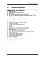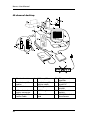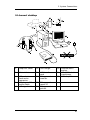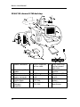
1
Quick Guide
MAN002
Quick Guide
MAN002
Taugagreining hf
Armuli 10
108 Reykjavík, Iceland
Tel: +354 580 7500
Fax: +354 580 7501
www.nervus.is
[email protected]
The Nervus range of Multimedia EEG systems has been designed and
manufactured by Taugagreining hf, an Icelandic company that has
always had an enviable reputation for innovation and quality of its
products.
Taugagreining hf has been certified by SEMKO as an
approved medical devices manufacturer as meeting the
requirements of the Medical Devices Directive
(93/42/EEC)
Taugagreining hf quality management system has been
certified by SEMKO-DEKRA to comply with ISO
9001:2000.
The Nervus range of EEG systems has been independently tested and
successfully approved to the following medical safety standards:
EN 60601-1, EN 60601-1-2, IEC 601-1, IEC 601-1-2, UL 2601-1, CAN/CSAC22.2 No. 601.1-M90, JIS T 1001/JIS T 1002 or JIS T 0601-1.
0413
The Nervus range of EEG systems is CE Marked in
accordance with the European Council Directive
93/42/EEC concerning medical devices.
Caution: in the USA federal law restricts this device to sale by,
or on the order of, a physician
Copyright
All rights reserved. This manual contains proprietary information which
is protected by copyright and may not be copied in whole or in part
except with the prior written permission of Taugagreining hf. The
copyright and the foregoing restrictions on the copyright use extend to
all media in which this information may be preserved.
This copy of the User Manual shall be used only in accordance with the
conditions of sale of Taugagreining hf or its distributors.
Taugagreining hf makes no representations or warranties of any kind
whatsoever with respect to this document. Taugagreining hf disclaims
all liabilities for loss or damage arising out of the possession, sale or use
of this document.
Nervus® is a registered trademark of Taugagreining hf.
Medelec® is a registered trademark of Oxford Instruments Medical.
TECA® is a registered trademark of Oxford Instruments Medical.
Microsoft® Windows®, Windows NT®, Windows XP® and Office® are
registered trademarks of Microsoft Corporation.
Intel Pentium® is a registered trademark of INTEL Corporation.
All other trademarks and product names are the property of their
relevant owners.
Taugagreining hf
Ármúli 10
108 Reykjavik
Iceland
Tel: +354 580 7500
Fax: +354 580 7501
www.nervus.is
iv
Contents
1
General Introduction
1.1 This Manual
1.2 Disclaimers and warranties
1.3 General handling precautions
1.4 Installation
1.5 The Nervus EEG system
1.6 Product variants
1.7 Maintenance
1.8 Electrical interference suppression
1
1
2
4
8
12
16
22
24
2
System connections
2.1 Connecting the equipment
2.2 Switching on and switching off
2.3 Connections diagrams
27
27
37
39
3
Quick Tour of Nervus
3.1 Nervus Study Room
3.2 The Nervus Recorder
3.3 The Nervus Reader
3.4 Pruning
53
53
55
58
60
v
vi
1 General Introduction
1 General Introduction
1.1
This Manual
Intended readers
The Nervus Multimedia EEG System facilitates the capture and review of
electroneurophysiological data. We have written this manual for those
experienced in this field – administrative staff, nurses, technicians and
physicians who will be using this application. As the Nervus System is
designed for the Microsoft® Windows® operating system, you will need
to be familiar with its basic features. Refer to the documentation
supplied with Microsoft® Windows®.
Basic organisation
This Quick Guide contains the first three chapters of the Nervus User
Manual and provides an overview of the equipment required for
operating the Nervus system, general handling and safety precautions,
and an outline of the system’s key features.
Other manuals
For more information, see also:
Nervus User Manual
Nervus Service Manual
Nervus System Administrator’s Guide
1
Nervus User Manual
1.2
Disclaimers and warranties
The information in this section is subject to change without notice.
Except as stated below, Taugagreining hf (TG) makes no warranty of any
kind with regard to this equipment, including, but not limited to, the
implied warranties of merchantability and fitness for a particular
purpose. TG shall not be liable for errors contained herein
or for incidental or consequential damages in connection with the
furnishing, performance or use of this equipment.
TG shall warrant its products against all defects in material and workmanship for one year from the date of delivery.
Misuse, accident, modification (including but not limited to the fitting
to the PC of cards and disk drives not approved by TG and the loading
of any software not approved by TG), unsuitable physical or operating
environment, improper maintenance or damage caused by a product for
which TG is not responsible will void the warranty.
TG does not warrant uninterrupted or error-free operation of its
products.
TG or its authorised agents will repair or replace any products which
prove to be defective during the warranty period, provided that these
products are used as prescribed in the operating instructions in the
user’s and service manuals.
No other party is authorised to make any warranty to assume liability
for TG’s products. TG will not recognise any other warranty, either
implied or in writing. In addition, services performed by someone other
than TG or its authorised agents or any technical modification or
changes of products without TG’s prior written consent may be cause for
invalidating this warranty.
2
1 General Introduction
Defective products or parts must be returned to TG or its authorised
agents, along with an explanation of the failure. Shipping costs must be
prepaid.
TG manufactures hardware and software to be used on or with standard
PC-compatible computers and operating software. TG, however, assumes
no responsibility for the use or reliability of its software or hardware
with equipment that is not furnished by third-party manufacturers
accepted by TG at the date of purchase.
All warranties for third-party products used within the Nervus EEG
System are the responsibility of the relevant manufacturer. Please refer
to the relevant documentation on each product for further details.
This document contains proprietary information that is protected by
copyright. All rights are reserved. No part of this document may be
photocopied, reproduced in any other form or translated into another
language without the prior written consent of TG.
© Taugagreining hf 2003
3
Nervus User Manual
1.3
General handling precautions
Staff qualifications and system components
The Nervus EEG system is intended for use only by qualified medical
personnel, doctors, specialists and technicians.
The Nervus system is a combination of software and hardware modules
manufactured by Taugagreining hf, and standard PC computer
equipment manufactured by third parties. The following specification
and safety standards apply to the system as a whole and individual
components manufactured by Taugagreining hf. For detailed
descriptions of third-party products, please refer to the relevant
documentation from manufacturers.
The system is based on a standard PC (tower or notebook) running the
Windows XP operating system. For faster processing and added ease,
standard PC equipment can be added, such as a printer, video cards etc.
Only PC cards and drives approved by Taugagreining hf may be fitted
into the PC. (Applies to Notebooks too).
Each part of the software, such as the Nervus Recorder for acquisition
and the Nervus Reader for reviewing, can be purchased individually for
each station.
For on-line storage, a hard disk can be added. Archiving requires
standard long-term storage media such as DVD+WR, optical drives, etc.
Important: any hardware connected to the system MUST be approved
by Taugagreining hf to ensure that it meets the medical safety
standards.
A recording station is equipped with a Nervus amplifier unit and
audio/video capture kit.
4
1 General Introduction
An ambulatory tape recorder, such as the Medelec MR95 recorder, can
be used to record ambulatory EEG signals which can be imported to the
Nervus EEG system via the Nervus HTP unit.
For networking, we recommend a dedicated Nervus PC running
Windows XP. The system can be adapted to most kinds of LAN, highspeed networks, ISDN, etc.
Safety standards
The system is designed to comply with the following medical safety
standards:
IEC601-1
International standard for medical electrical
equipment, general requirements for safety.
EN60601-1
European standard for medical electrical
equipment, general requirements for safety.
UL2601-1
USA standard for medical electrical equipment,
general requirements for safety.
CAN/CSA 22.2
Canadian standard for medical electrical
NO.601.1
equipment, general requirements for safety.
EN60601-1-1
European standard for medical electrical
equipment, collateral standard safety requirement
for medical electrical systems.
EN60601-1-2
European standard for medical electrical
equipment, collateral standard - Electromagnetic
compatibility.
EN60601-2-26
European standard for medical electrical
equipment – particular requirements for the
safety of electroencephalographs.
5
Nervus User Manual
Type of protection against electrical shock
Class 1
Degree of protection against electrical shock
Type BF
Degree of protection against harmful ingress
of water
Ordinary (no
protection)
Mode of operation
Continuous
Degree of safety of application in the presence
of a flammable anaesthetic mixture with air or
with oxygen or nitrous oxide
Not suitable
Cautions and warnings
It is the responsibility of the user to ensure that conformance to EN
60601-1 Type BF patient isolation requirements is maintained when
patient-connected equipment or accessories not supplied by
Taugagreining hf or its authorised agent are used with Taugagreining
hf equipment.
Full compliance of Nervus systems cannot be ensured unless all components (leads etc.) are provided by Taugagreining hf or it authorised
agent.
Any non-medical equipment connected to medical equipment to form a
medical electrical system must comply with an appropriate safety
standard, for example IEC60950, EN60950, UL1950, CAN/CSA22.2 No 950.
Items not specified as part of a Nervus system must not be connected to
a Nervus system.
The operator must not touch any parts of non-medical electrical
equipment (monitor, PC, printer, etc) supplied as part of the Nervus
system that may be exposed after removal of covers, connectors, etc
which do not require the use of a tool and the patient simultaneously.
For example, do not touch the pins of the serial port connector on the
PC and the patient simultaneously.
The brakes fitted to the trolley castors should be applied whenever the
system is left unattended.
6
1 General Introduction
Leakage current
This instrument is designed to comply with the European standard for
medical electronic equipment EN60601-1, which lays down the permissible levels of leakage current from individual products. A potential
hazard exists in the summation of leakage currents caused by
connecting multiple pieces of equipment together. Because this
instrument can be used in conjunction with standard electronic devices,
the total leakage current should be tested at regular intervals.
Responsibility of manufacturer
The manufacturer and distributor consider themselves responsible for
the equipment’s safety, reliability and performance only if:
l the Nervus system is run on standard PC equipment from third-party
providers recommended by the manufacturer.
l assembly operations, extensions, readjustments, modifications, or
repairs are carried out by persons authorised by the manufacturer;
l the electrical installation of the relevant room complies with the
appropriate requirements;
l the equipment is used in accordance with the instructions for use.
Note: the manufacturer has a policy of continual product improvement;
hence the equipment specifications are subject to change without
notice.
Disposal of equipment
When the equipment comes to the end of its operating life, it should be
disposed of in accordance with local waste disposal regulations. Advice
on this can usually be obtained from the local waste regulation
authority which is typically found within the local government office.
7
Nervus User Manual
1.4
Installation
Warnings
The following section must be read and understood before the equipment is switched ON.
The function or safety of the equipment could be impaired if it has been
subjected to unfavorable conditions in storage or in transit. If, at any
time, function or safety is thought to be impaired, the instrument
should be taken out of operation and secured against unintended use.
Advice to the installer
To enable the user to achieve optimal use, the installer should ensure
that:
l all cables are routed neatly and secured using the cable management
facilities provided;
l the system is connected to a suitable wall socket outlet with a proven
protective earth connection;
l on systems using the single pole trolley, the heights of the
keyboard/notebook shelf, the LCD monitor (tower PC systems) and
the amplifier and photic stimulator arm mounting blocks allow the
user to operate the equipment comfortably;
l the system is handed over to the user in such a condition that the
user may simply switch it on and then use it for its intended purpose.
8
1 General Introduction
Checks for completeness and integrity
Remove the equipment from the packaging case(s) and use the parts list
to check that all ordered items have been received.
Assembly instructions for third-party products may be found in their
packing cases. It is recommended that these instructions be filed with
Nervus technical reference materials.
Check for signs of damage which may have occurred during transit or
storage. If any damage is found, do not use the instrument; contact your
distributor.
Environmental parameters for operation
The equipment is designed to operate within the following ranges:
Temperature
+5°C to +35°C (+41°F to +95°F)
Relative humidity
20% to 80% RH (non-condensing)
Atmospheric pressure range
700-1060 hPa
During transport and storage, the following ranges are tolerated:
Temperature
–20°C to +65°C (–4°F to 149°F)
Relative humidity
10% to 85% RH (non-condensing)
Atmospheric pressure range
500-1060 hPa
l
l
l
l
Do not obstruct the cooling slots.
Position the equipment so that air flows freely from the
cooling slots.
Do not use the equipment in the presence of flammable,
anaesthetic gases.
All parts of the Nervus systems supplied by Taugagreining hf
may be placed within the patient environment.
9
Nervus User Manual
Power supply connections
Nervus systems are suitable for connection to a single phase public
mains supply network. The wall socket outlet(s) to which a Nervus
system is connected must provide a protective earth connection.
Power requirements for the complete system
For systems with ISO1000 transformer:
100-120V/200-240V~ (user adjustable in mains inlet module); 1050VA for
110-120V/200-240V~ input (950VA for 100V~ input); 50/60Hz
For notebook systems:
100V–240V; 70VA; 50/60Hz for medical power supply
115V/230V; 50VA; 50/60Hz for photic stimulator
For the power requirements of the notebook PC and printer, refer to the
user manuals supplied by the manufacturers.
Mains power connections
Instruments supplied in the USA and Canada have a power cord,
connector and a hospital-grade AC mains power plug. Note that in the
USA grounding reliability can only be achieved when the equipment is
connected to an equivalent receptacle marked Hospital Only or Hospital
Grade.
Instruments supplied to other countries have a power cord and
connector, but may not have a mains power plug.
The wires of the mains power cable are color-coded:
color
brown
blue
green/yellow
10
connection
live
neutral
protective earth
1 General Introduction
When a mains plug is fitted, ensure that the correct connections are
made.
The protective earth wire (green/yellow) must be connected to the
protective earth conductor.
For instruments supplied in the UK, the USA and Canada, the protective
earth connection is automatic when an appropriate and correctly wired
socket is used.
When the mains plug is designed to hold a fuse, a 7A rated fuse should
be used for the lead supplying the ISO1000; a 3A fuse should be used for
the ‘Y’ lead supplying the medical power supply PSU001 and the power
supply for the notebook PC.
The power cord and connector supplied with the instrument or a lead
and connector of equivalent standard should be used with the
instrument. Do not use adapter plugs or extension leads.
Only appropriately trained and qualified personnel should adjust,
maintain or repair an instrument when it is connected to the mains
electricity supply. If the cover must be removed, the instrument should
be disconnected from the mains electricity supply.
Note: please refer to appropriate technical manuals for detailed
information on third-party products.
11
Nervus User Manual
1.5
The Nervus EEG system
The Nervus Multimedia EEG system records and processes EEG and
polygraphy signals using a standard PC running Windows XP. The
following section covers key features of the Nervus system and the software components.
Key features
l
l
l
l
l
l
l
l
l
l
l
l
l
l
l
Use of the Windows XP operating system to record and process
digital EEG data;
Seamless integration with standard software such as Microsoft Office.
Acquisition of up to 128 EEG channels and other biological signals
and storage to a file;
Simultaneous acquisition and display of data, including digital video;
Insertion of user-defined and automatically inserted event markers
during recording, and the ability to browse the recording by events;
Custom montages (with complete control of paper speed, sensitivity,
signal derivation and filter settings);
Review of previous parts of the recording while still recording;
Page-by-page browsing through a recording or continuous playback
(forward or backward);
Trend Overview and the ability to browse the recording by selecting
a point on the overview;
Recording Protocol: a group of format and view settings, with instant
return to saved configurations;
Photic stimulation control from the recorder. The user can create
their own Photic sequences and execute them from the recorder.
Duration events specifying the frequency are inserted while flashing;
Hyperventilation and Reaction Time tools;
Continuous Impedance Testing while recording with automatic event
insertion when a poor electrode connection is detected;
Low cut, high cut and notch filtering;
Calculation of Fourier transformation.
Optional features
l Acquisition of digital video to a file and synchronization to the EEG;
12
1 General Introduction
l
Alerts – Notification by email or a custom launched program when
specified events occur.
Software
The Nervus software co-ordinates all the hardware functions, translates
the data into a comprehensible form, performs some automatic analysis
and provides an interface enabling you to operate the system. Nervus
consists of a number of software modules:
Nervus Study Room
Nervus’s starting point, this program provides access to all other parts of
the system, such as recording, reviewing or archiving an EEG recording,
opening a patient folder or editing a patient entry in the Nervus
database.
Nervus Recorder
This program is used for the acquisition of EEG. The program allows you
to acquire, mark and record comments on electro-physiological data
and to record synchronous digital video.
Nervus Reader
This application enables you to review and analyse EEG files, supporting
derivation, filtering, and topographical maps.
13
Nervus User Manual
Nervus accessories
A wide variety of accessories is available for Nervus systems including
electrode kits. Please contact your local distributor for details.
Nervus concepts and terminology
Nervus is a multimedia EEG system based on standard, IBM-compatible
PC computer equipment. The Nervus software operates within the
Microsoft Windows environment; thus users who are familiar with
Windows will feel at home when working with Nervus. Floating
toolbars, menus, mouse clicks etc., follow standard Windows guidelines,
and in this manual we assume that you are familiar with these devices
and operations. If not, please refer to your Windows documentation for
more information.
Multimedia EEG
The Nervus Multimedia EEG system uses synchronous digital video with
the corresponding physiological information.
Storing EEG data in a digital format has many advantages over the
conventional methods. Data can be reviewed and reformatted, thus
enhancing the clinical utility of each recording. Tests can easily be
accessed and reformatted by anyone connected to the central database.
Reports can include visual information obtained directly from the
source, including EEG traces, topographical maps and video recordings
of the patient. Even live links can be inserted giving direct access to data
for further analyses.
14
1 General Introduction
Standard Interface
Because of the standard Windows interface to the system, you are
always on familiar ground, regardless of the application you are using.
You do not have to learn multiple commands and functions. Also, this
arrangement offers a unique way of interfacing the EEG tests and data
with standard reporting applications such as MS Word for Windows.
Anti-virus software
There are a number of file types associated with the Nervus system that
must be excluded when scanning disks with anti virus software. The
method for specifying file types for exclusion varies according to the
anti virus software package you are using. Please refer to the
documentation accompanying the anti virus software for instructions on
how to do this.
The following file types must be excluded:
*.e
*.avi
*.eeg
*.edf
*.bsa
*.95
15
Nervus User Manual
1.6
Product variants
The Nervus Multimedia EEG system is available in a variety of product
variants.
l 40 Channel Desktop
l 24 Channel Desktop
l 32/64/128 Channel LTM Desktop
l 32 Channel USB Notebook
l 40 Channel Notebook
l 24 Channel Notebook
The Nervus 40 Channel Desktop uses a tower PC and the M40
amplifier which handles up to 40 EEG and polygraphy channels. It
requires the installation of the USBIFB/01 interface card in the tower PC.
The M40 amplifier supports electrode impedance checking.
The Nervus 24 Channel Desktop uses a tower PC and the M24
amplifier which handles up to 24 EEG and polygraphy channels. It
requires the installation of the USBIFB/01 interface card in the tower PC.
The M24 amplifier supports electrode impedance checking.
The Nervus 32/64/128 Channel LTM Desktop uses a tower PC and the
C32 or C64 compact amplifier which handles 64 channels, or 2 amplifiers
can be connected to handle 128 channels. This system requires the
USBIFB/01 interface card to be installed in the tower PC.
The Nervus 32 Channel USB Notebook uses a notebook PC and the
U32 USB amplifier which handles up to 32 channels and connects
directly to the USB port of the computer.
The Nervus 40 Channel Notebook uses a notebook PC and the M40
amplifier. This system requires the Ibox interface box to connect the
amplifier to the notebook PC.
The Nervus 24 Channel Notebook uses a notebook PC and the M24
amplifier. This system requires the Ibox interface box to connect the
amplifier to the notebook PC.
All Nervus amplifiers are fitted with a green LED to indicate when power
is applied to them.
16
1 General Introduction
The table on the following pages shows the standard and optional
components of each variant.
17
Nervus User Manual
Nervus System Configurations
32 channel USB Notebook
40 channel Notebook
24 channnel Notebook
Desktop PC
X
X
X
-
-
-
Notebook PC
-
-
-
X
X
X
Monitor
X
X
X
-
-
-
M40 Amplifier
X
-
-
-
X
-
C32 Amplifier
-
-
O
-
-
-
C64 Amplifier
-
-
O
-
-
-
U32 Amplifier
-
-
-
X
-
-
M24 Amplifier
-
X
-
-
-
X
IBox
-
-
-
-
X
X
Nervus Photic
O
O
O
O
O
O
ISO1000
X
X
X
-
-
-
ISB060W
-
-
-
Oi
Oi
Oi
Medical Power
Supply PSU001
-
-
-
X
X
X
32/64/128 channel LTM
Desktop
24 channel Desktop
O = Optional
40 channel Desktop
X = Standard
Hardware
Required if printer or other externally powered peripherals are to
be connected to the system
i
18
1 General Introduction
Accessories
Single Pole
O
O
O
O
O
O
Knurr Trolley
O
O
O
-
-
-
Minicart
-
-
-
O
O
O
Carry Case
-
-
-
X
X
X
Study Room
X
O
X
X
X
O
Recorder
X
X
X
X
X
X
Reader
X
X
X
X
X
X
Video
O
O
O
O
O
O
Spike & Seizure
O
O
X
O
O
O
Trend Analysis
O
O
X
O
O
O
Selective Video
O
O
X
O
O
O
Alerts
O
O
X
O
O
O
Maps
O
O
O
O
O
O
Software
A range of accessories is available. Please contact the manufacturer or
your local distributor for details.
19
Nervus User Manual
Transporting the system
Follow the procedures for switching OFF (see above) before transporting
the system.
Note: it is important to remove all disks from floppy and optical drives.
If this is not done, the drives may be damaged.
Special instructions for use
General
Switch ON the instrument (see chapter 2) before connecting patient
electrodes.
Disconnect all patient electrodes before switching OFF (see chapter 2).
Conductive parts of the electrodes, including the neutral electrode,
should not come into contact with other conductive parts including
earth.
Switch OFF the mains electricity supply and pull out the mains electricity
supply plug before disconnecting any items of equipment.
Defibrillators
IMPORTANT:
Before a defibrillator is used on the patient, disconnect the
amplifier from the Nervus system as described below:
U32 systems
M40 systems
M24 systems
C32, C64
20
Disconnect the USB cable, the dc power cable and
the photic stimulator cable from the U32 amplifier.
Disconnect the amplifier/photic cable from the M40
amplifier.
Disconnect the amplifier/photic cable from the M24
amplifier.
Disconnect the quick release connectors joining the
compact amplifier cable to the compact amplifier
single or double cable.
1 General Introduction
Using electrosurgical systems: risk of burns
During electrosurgical procedures, high levels of radio frequency power
are used and burns may occur at sites other than those intended, in
particular at the sites of monitoring electrodes.
If you intend to use electrosurgical equipment at the same time as the
Nervus, please take the following precautions:
l
l
l
Use isolated-type diathermy equipment which meets the
requirements of EN60601-2-2.
Use diathermy equipment which continuously monitors the
impedance of the connection to the dispersive electrode and warns
when the impedance becomes unacceptably high
Follow the manufacturer’s instructions for the attachment of the
dispersive electrode:
Do not permit the active diathermy electrode to become grounded
when it is energised. This can cause severe burns at the site of
monitoring electrodes due to electrical current flowing from the
dispersive electrode to ground via the active diathermy electrode.
Use electrodes with large monitoring areas where possible. Do not use
electrodes with small monitoring areas, for example needle electrodes.
These electrodes concentrate the radio frequency energy more than
large area recording electrodes and make the recording sites more
susceptible to burns.
When small area electrodes have to be used, add a 10kΩ resistor in
series with each recording electrode to reduce the risk of burns. Do not
put a resistor in series with the neutral electrode because this will
degrade the quality of the recording - use a large area neutral
electrode.
21
Nervus User Manual
1.7
Maintenance
Warning: there are no user-serviceable parts inside the instrument. Only appropriately trained and qualified personnel should
adjust, maintain or repair the instrument when it is connected
to the electricity supply. The instrument must be disconnected
from the electricity supply first, before any cover is removed.
The Nervus EEG System contains many solid-state electronic components
which need no maintenance and no parts requiring periodic
replacement. Furthermore, most hardware components of the Nervus
system are standard PC equipment. They should be maintained
according to the relevant manufacturer’s directions.
The notebook PC must only be powered by the model of power supply
originally supplied with the system by Taugagreining hf. Note that the
use of other models of power supply from the manufacturer of the PC
or from other manufacturers, whilst they may power the PC correctly,
may not comply with the leakage current requirements defined in the
medical electrical systems standard EN60601-1-1.
Therefore in the event of failure the power supply for the notebook PC
must only be replaced by one of the same make and model.
After-sales service support
The manufacturer and distributors of Nervus EEG systems provide
comprehensive after-sales service and support. Service contracts are
available. For details, please contact the manufacturer or the local
distributor.
A service manual is available for purchase containing all the information
necessary to enable appropriately qualified technical personnel to carry
out repair and calibration of those parts of the equipment that are
repairable.
22
1 General Introduction
Fuses
Before removing a fuse, switch off the instrument and pull out the
mains plug. Use a screwdriver to ease out the twin fuseholder. The fuses
are extracted with the fuse holder and are simply pulled out.
Nervus Photic F1/F2
ISO1000 Isolation Transformer F3/F4:
2 x T500 mA L 250V
200-240V – T6.3A H 250V
100-120V – T10A H 250V
If fuses fail repeatedly, contact the manufacturer or the local distributor.
For information on any user-accessible fuses in the PC, monitor and
printer, please refer to the relevant third-party manufacturer
documentation.
Regular testing of equipment and accessories
Checks may be made using the inbuilt calibration and impedance check
functions to confirm that the equipment and its accessories are operating correctly.
Cleaning
The user is advised to carry out cleaning as specified below, as and when
required:
l All the outer surfaces of the individual pieces of equipment of the
Nervus system may be cleaned using a cloth moistened with water
and detergent. Do not allow any liquid to enter the case of any
instrument.
l Each item may also be cleaned using a low-pressure air-line, or a
vacuum cleaner with an appropriate attachment.
l Do not use propanone (acetone) on any of the instruments.
l No part of the system may be autoclaved or sterilised by any means.
l For advice on methods and frequency of cleaning the PC, monitor
and printer consult the documentation supplied with them.
23
Nervus User Manual
1.8
Electrical interference suppression
These notes are intended as a guide to identifying and suppressing
electrical interference that may affect apparatus involving the detection
and analysis of signals of a few microvolts in the frequency range DC to
20kHz, such as for Electroencephalographs (EEG).
Classification of interference sources
1 50Hz/60Hz magnetic field from power transformers, induction
motors, etc
The only practical protection from this type of interference is the
avoidance of loops in the pick-up circuits of the EEG, since the
magnitude of the interfering voltages is directly proportional to the
area enclosed by any such loop.
2 Magnetic field from staff location systems using inductive
loops
This type of interference is of an intermittent character and may be
serious where the inductive loop runs alongside the wall of the
examination room and where the transmitted frequencies fall within the
pass band of the EEG (DC to 20kHz).
Most modern staff location systems now use frequencies above 20kHz
and should therefore cause minimum interference unless the loop is very
close to the EEG.
24
1 General Introduction
3 50Hz/60Hz electrostatic field from unshielded conductors,
lamps, etc.
This type of interference is possibly the simplest to locate and correct.
Any conductor of supply frequency not covered by an earthed metal
screen is a potential source of interference. Obvious sources are flexible
cables to desk lamps and X-ray viewing boxes, unshielded flourescent
tubes and filament lamps.
It is important that all encasing metalwork of electrical equipment be
securely bonded electrically to the local circuit earth.
4 HF interference from short-wave diathermy, radio, television
and sound broadcasting
This class of interference is the most difficult to track down to its source
and by far the most difficult to eliminate.
Short-wave diathermy is easily the most frequent source of HF
interference, particularly in or near a physical medicine department or
operating theatre.
The interference may reach the EEG via a number of paths falling into two
main categories: (1) Conducted and (2) Radiated.
Conducted HF interference is the type found on the mains supply. This
kind of interference is eliminated by efficient mains filtering on
equipment.
Radiated interference is emitted from poorly screened electrical
equipment or other sources such as cell phones, radio transmitters and
hospital paging systems. In severe cases, a screened enclosure is
essential.
25
Nervus User Manual
Sources of artefact
l
l
l
l
l
l
l
l
l
l
l
l
l
l
l
l
l
l
l
l
26
Dirty electrodes
Broken electrode lead wire including ground electrode wire
Electrode lead wire movement
Poor ground electrode location
Incorrect electrode connection to apparatus
Ungrounded wheelchair or table
Ungrounded observers
Microphony
Audio feedback
Pick-up from CRT screen
Power cables near patient not unplugged at wall socket
Poor apparatus ground
Fluorescent lights
Electronic dimmers
Intermittent power line load
Excessive low or high power line voltage
Diathermy
Radio and TV
Multiple grounds in screened room
Cell Phones
2 System Connections
2 System connections
2.1
Connecting the equipment
IMPORTANT:
For connections to the mains supply do not use any additional multiple
portable socket outlets, adapter plugs, or extension leads. In particular
the use of a multiple portable socket outlets runs the risks of a) the
summation of earth leakage currents which may result in the allowable
limits for medical electrical equipment and systems being exceeded, and
b) the protective earthing of the system relying on the single earth
connection to the multiple portable socket outlet.
Connect all the individual items of equipment before switching ON.
Connect only peripheral equipment supplied or approved by the
manufacturer of the Nervus system.
Connecting the mains (Desktop systems)
Checks before switching on the system
l Check that the ISO1000 mains isolation transformer input voltage is
set to match output voltage for your local mains supply.
l Check that the input voltages of the photic stimulator, the PC tower,
the monitor and the optional printer are all set to match the output
voltage of the ISO1000. Refer to the rating labels and user manuals
of these equipments to check if adjustment is necessary and for
information on how to carry out any required adjustments.
27
Nervus User Manual
Notes and warnings
Note that the photic stimulator may be powered either directly from a
separate wall socket outlet (do not use a multiple portable socket outlet)
or from an outlet on the ISO1000 Mains Isolating Transformer, whichever is
more convenient.
The non-medical equipment supplied as part of the Nervus Desktop
systems – the tower PC, the monitor and the printer - must only be
powered from the outlets of the ISO1000 mains isolation transformer. If
non-medical equipment supplied as part of the Nervus Desktop systems
were to be connected directly to a wall socket outlet then there may be
a risk of allowable leakage currents being exceeded.
Note that the outlets of the ISO1000 mains isolation transformer must
only be used to power equipment approved by Taugagreining hf. No
other equipment may be powered from these outlets as there may be a
risk of exceeding the power rating of the ISO1000 mains isolation
transformer.
The maximum permitted load for the ISO1000 mains isolation
transformer is 1000VA for 110-120V/200-240V~ ( 900VA for 100V~ ).
Check that the ISO1000 mains isolation transformer is not placed on the
floor. A position is provided for it on the bottom shelf of the trolley.
Connection
Connect the mains supply to the mains input connector of the ISO1000
mains isolation transformer using the lead supplied. Then connect the
PC tower, the monitor and the printer to the isolated mains outlets of
the mains isolation transformer using the IEC plug to IEC socket leads
supplied with the system.
28
2 System Connections
Connecting the mains (Notebook systems)
Note: if you are using a printer with the notebook PC, then a mains
isolation transformer is required. If you are using the notebook PC
supplied by Taugagreining hf, and do not have a printer connected,
then you do not need a mains isolation transformer.
Connect the medical power supply PSU001 and the power supply
provided by the manufacturer of the notebook PC to the mains supply
using the special ’Y’-mains cable supplied with the system.
The notebook PC must only be powered by the model of power supply
originally supplied with the system by Taugagreining hf. Note that the
use of other models of power supply from the manufacturer of the PC
or from other manufacturers, whilst they may power the PC correctly,
may not comply with the leakage current requirements defined in the
medical electrical systems standard EN60601-1-1.
Note that the Photic Stimulator and the Taugagreining hf approved
printer must be powered directly from separate wall socket
outlets otherwise allowable leakage currents may be exceeded. Do not
use a multiple portable socket outlet.
Note that the printer(s) recommended by Taugagreining hf have been
selected to comply with the earth leakage current requirements of
standard EN 60601-1-1, safety requirements for medical electrical
systems. The use of a printer other than one recommended by
Taugagreining hf may result in allowable leakage currents being
exceeded.
29
Nervus User Manual
USBIFB/01 interface card (Desktop PC systems)
Connect the 300mm USB A-B cable supplied between the USB port of
the PC and the USB port of the interface card. Connect the splitter cable
to the 15 pin high density D-type socket. A 26-pin high density D-type
socket is available for optional analogue in.
Note: make sure you are connecting the USB cable to the USB port on
the PC, and not to the Network connector.
Nervus IBox and Medical Power Supply PSU001
Connect the USB A-B cable supplied between the USB connector on the
end panel of the IBox and one of the USB connectors on the notebook
PC - note that a different type of connector is used at each end of the
USB cable.
Connect the dc power cable supplied, fitted with miniature 4pin circular
connectors, between the socket on the junction box attached to the
medical power supply PSU001 and the dc input plug on the end panel of
the Ibox. These connectors simply push together and lock with an
audible click. To disconnect pull (do not twist) the connectors apart.
Warning: in order to maintain patient and user safety, the
Nervus IBox must only be powered from the medical power
supply PSU001 .
30
2 System Connections
M40 amplifier
(40 channel systems)
Two cables are supplied to connect the M40 amplifier to the Nervus 40
channel desktop or notebook system - a splitter cable and an
amplifier/photic cable. Both these cables are fitted with 15pin high
density D-type plugs and sockets.
For the notebook system: connect the plug of the splitter cable to
the 15pin socket on the end panel of the Ibox interface unit.
For the desktop system: connect the plug of the splitter cable to the
15pin socket on the USBIFB/01 interface card fitted in the tower PC.
For both systems the plug of the amplifier/photic cable is connected to
either of the two sockets of the splitter cable. The socket of the
amplifier/photic cable is connected to the plug on the end panel of the
Nervus M40 amplifier. (The second socket of the splitter cable is used to
connect the photic stimulator.)
Tighten the jackscrews on all connectors so fitted.
31
Nervus User Manual
C32 and C64 compact amplifier
(32, 64 or 128 channel systems)
Note: the 32 channel Nervus system uses one C32 amplifier; the 64
channel Nervus system uses one C64 amplifier; the 128 channel Nervus
system uses two C64 amplifiers.
Three cables are required to connect the C32, C64 or C128 compact
amplifier to a 32, 64 or 128 channel system - a splitter cable, a compact
amplifier cable, and either a compact amplifier single cable for the 32
and 64 channel system or a compact amplifier double cable for the 128
channel system.
Connect the plug of the splitter cable to the 15pin socket on the
USBIFB/01 interface card fitted in the tower PC.
Connect the 15pin high density D-type plug of the compact amplifier
cable to either of the two sockets of the splitter cable. Connect the
quick release connector at the other end of the compact amplifier cable
to the mating connector on either the compact amplifier single cable for
the 32 and 64 channel system or the compact amplifier double cable for
the 128 channel system.
Connect the 36pin SCSI connector(s) on the compact amplifier single
cable or the compact amplifier double cable to the mating connector(s)
on the C32 or C64 amplifier(s).
Tighten the jackscrews on all connectors so fitted.
32
2 System Connections
U32 amplifier
(32 channel notebook system)
Connect the USB A-B cable supplied between the USB connector on the
end panel of the U32 amplifier and one of the USB connectors on the
notebook PC - note that a different type of connector is used at each
end of the USB cable.
Connect the dc power cable supplied, fitted with miniature 4pin circular
connectors, between the socket on the junction box attached to the
medical power supply PSU001 and the dc input plug on the end panel of
the Nervus 32 amplifier. These connectors simply push together and lock
with an audible click. To disconnect pull (do not twist) the connectors
apart.
WARNING: in order to maintain patient and user safety, the U32
amplifier must only be powered from the medical power supply
PSU001 .
33
Nervus User Manual
M24 amplifier
(24 channel systems)
Two cables are supplied to connect the M24 amplifier to the Nervus 24
channel desktop or notebook system - a splitter cable and an
amplifier/photic cable. Both these cables are fitted with 15pin high
density D-type plugs and sockets.
For the notebook system: connect the plug of the splitter cable to
the 15pin socket on the end panel of the Ibox interface unit.
For the desktop system: connect the plug of the splitter cable to the
15pin socket on the USBIFB/01 interface card fitted in the tower PC.
For both systems the plug of the amplifier/photic cable is connected to
either of the two sockets of the splitter cable. The socket of the
amplifier/photic cable is connected to the plug on the end panel of the
Nervus M24 amplifier. (The second socket of the splitter cable is used to
connect the photic stimulator.)
Tighten the jackscrews on all connectors so fitted.
34
2 System Connections
Photic stimulator
A second amplifier/photic cable is supplied for connection of the photic
stimulator.
For the desktop systems
Connect the plug of the amplifier/photic cable to the second 15pin
socket of the splitter cable connected to the USBIFB/01 interface card
when the amplifier was connected.
Connect the socket of the amplifier/photic cable to the 15pin plug on
the rear panel of the photic stimulator.
Tighten the jackscrews on all connectors so fitted.
For the notebook system
Connect the plug of the amplifier/photic cable to the 15pin socket on
the end panel of the U32 amplifier for 32 channel notebook system or
the IBox for 24 and 40 channel notebook system.
Connect the socket of the amplifier/photic cable to the 15pin plug on
the rear panel of the photic stimulator.
Tighten the jackscrews on all connectors so fitted.
35
Nervus User Manual
Other standard PC equipment
Please refer to relevant technical guides for the PC, monitor and printer
for the positions of the relevant signal connectors. Suitable signal cables
are provided with the system for connecting these equipments. High
quality screened cables must be used when connecting to the interface
connectors of Nervus to ensure compliance with EMC regulations. Braid
screened or double screened (braid plus foil) cables are the preferred
types. The cable screen should make a 360° connection to the screening
shells of the connectors on each end of the cable.
Note that only printers approved by Taugagreining hf may be used with
Nervus EEG systems configured without a mains isolation transformer.
This is to ensure that these systems comply with the leakage current
requirements defined in the medical electrical systems standard
EN60601-1-1.
Cables
l
l
l
l
Position the equipment so that cables are not stretched and cannot
be pulled at or tripped over.
Always disconnect cables by pulling the plug, not the cables.
Wires within a cable may be damaged if the cable is stretched or
improperly disconnected; this damage may cause a failure in the
supply of power or acquisition of data.
It is recommended that cables and connectors are frequently visually
inspected for signs of wear (for example, cracks or breaks). If
necessary, do not use the cable but have it removed for service.
Dongle (copy protection key)
To run the software, the dongle must be plugged into a USB port of
your computer.
36
2 System Connections
2.2
Switching on and switching off
Switching ON
Notes:
As a safety precaution, switch ON before connecting patient electrodes.
Do not disconnect any item of equipment when mains electricity is
connected. (This does not apply to equipment utilising the USB
Universal Serial Bus).
1 Connect all the peripheral items of equipment before switching ON.
Connect only peripheral equipment supplied or recommended by
Taugagreining hf.
2 Identify the connector on each of the electrical leads on individual
items of equipment and push them firmly into position on the rear
panel of the PC.
3 Before switching ON the PC make sure no floppy disk is in the
external disk drive.
4 Connect the mains electricity supply and switch ON at the mains
power plug. The mains power ON/OFF switch on the PC is a rocker or
push button switch on the front of the panel. The indicator light on
the front of the panel is ON when the switch is ON.
5 Press the power on button to start the PC. The PC is now ON and starts
loading the appropriate Windows operating system (Windows XP).
Passwords
You must enter a user name and password before you can run Nervus
software or access any data. If you do not know what your user name
and password are, consult your System Administrator.
37
Nervus User Manual
Switching OFF
IMPORTANT: disconnect all patient electrodes before switching OFF.
1 Remove any floppy disk from the external drive and any optical disks
before switching OFF.
2 Shut down the system using the Windows shutdown procedure.
3 Switch OFF at the mains power plug.
38
2 System Connections
2.3
Connections diagrams
Combined key for all diagrams
1
2
3
4
5
6
7
8
9
10
11
12
14
16
17
18
19
20
21
22
23
24
25
26
27
28
29
30
31
32
33
35
36
37
Photic stimulator
Photic and M40 amplifier signal cable
Mains inlet
IEC socket to local mains connector (3 core 16AWG)
IEC plug to IEC socket cable – output of ISO 1000 to PC tower, monitor,
printer etc.
M40 amplifier
U32 amplifier
C32 or C64 compact amplifier
dc power to IBox or U32 amplifier
IBox interface
USB signal cable
Splitter cable for photic and amplifier signals
Medical power supply
Taugagreining hf approved notebook PC
Mouse
Keyboard
USB signal cable ~ USB interface card to PC USB port
Nervus software hardware licence key (USB Dongle)
USB interface card
Long cable for C32 / C64 compact amplifier
Short cable for C32 / C64 compact amplifier
Short cable with link cable for second C32 / C64 compact amplifier
Monitor signal cable
Taugagreining hf approved monitor
Taugagreining hf approved tower PC
Taugagreining hf approved printer
Signal cable to printer
Isolated mains outlets
Isolation transformer (ISO1000 or ISB060W)
Separate fixed mains socket outlets
Wall of room
M24 amplifier
Junction Box
DC Power to Junction box
39
Nervus User Manual
40 channel desktop
1
Photic stimulator
6
M40 amplifier
26
2
Photic / amplifier
cables
Mains inlet
12
27
19
Photic / amplifier
splitter cable
USB signal cable
IEC socket to local
mains connector
IEC plug to IEC
socket cable
20
USB Dongle
30
21
USB interface
card
31
3
4
5
40
28
TG approved
monitor
TG approved
tower PC
TG approved
printer
Isolated mains
outlets
ISO 1000 isolation
transformer
2 System Connections
24 channel desktop
2
Amplifier cables
20
USB Dongle
30
3
Mains inlet
21
31
4
IEC socket to
local mains
connector
IEC plug to IEC
socket cable
USB signal cable
26
USB interface
card
TG approved
monitor
5
19
27
28
35
Isolated mains
outlets
ISO 1000 isolation
transformer
M24 Amplifier
TG approved
tower PC
TG approved
printer
41
Nervus User Manual
32/64/128 channel LTM desktop
1
Photic stimulator
12
Photic / amplifier
splitter cable
24
2
Photic / amplifier
cables
Mains inlet
IEC socket to local
mains connector
IEC plug to IEC
socket cable
C32 or C64
compact
amplifier
19
USB signal cable
26
20
21
USB Dongle
USB interface
card
Long cable for
C32 / C64
Short cable for
C32 / C64
27
28
3
4
5
8
42
22
23
30
31
Short cable with
link for second
C32 / C64
TG approved
monitor
TG approved PC
TG approved
printer
Isolated mains
outlets
ISO 1000 isolation
transformer
2 System Connections
32 channel USB notebook
1
Photic stimulator
9
dc power to U32
35
2
Photic / amplifier
cables
Mains inlet
11
USB signal cable
36
14
37
16
Medical power
supply
Notebook PC
20
USB Dongle
3
4
7
IEC socket to local
mains connector
U32 amplifier
DC power to
Notebook PC
Junction Box
DC power to
Junction Box
43
Nervus User Manual
40 channel notebook
1
2
3
4
6
44
Photic stimulator
Photic / amplifier
cables
Mains inlet
9
10
dc power to IBox
IBox interface
16
20
Notebook PC
USB Dongle
11
USB signal cable
35
IEC socket to local
mains connector
M40 amplifier
12
Photic / amplifier
splitter cable
Medical power
supply
36
DC power to
Notebook PC
Junction Box
14
37
DC power to
Junction Box
2 System Connections
24 channel notebook
1
2
3
4
6
Photic stimulator
Photic / amplifier
cables
Mains inlet
IEC socket to local
mains connector
M24 amplifier
9
10
dc power to IBox
IBox interface
16
20
Notebook PC
USB Dongle
11
USB signal cable
35
12
Photic / amplifier
splitter cable
Medical power
supply
36
DC power to
Notebook PC
Junction Box
14
37
DC power to
Junction Box
45
Nervus User Manual
Adding a printer to notebook systems
1
Photic stimulator
5
2
Photic / amplifier
cables
Mains inlet
14
IEC socket to local
mains connector
29
3
4
46
28
IEC plug to IEC
socket cable
Medical power
supply
TG approved
printer
Signal cable to
printer
30
31
37
Isolated mains
outlets
Isolation
transformer
DC power to
Junction Box
2 System Connections
Symbols and their definitions
v
Z
w
x
N
f
e
A
O
P
Q
S
U
Z
i
K
Direct current (DC)
Alternating current (AC)
Off (main power supply)
On (main power supply)
Mains Isolation Transformer
Danger – high voltage
Type BF patient applied part
Refer to accompanying documents
Caution: to reduce the risk of electric shock do not
remove cover. Refer servicing to qualified service
personnel.
Before connecting refer to user manual.
Danger: risk of explosion if used in the presence of
flammable anaesthetics.
No user serviceable parts inside.
Before connecting ensure that mains voltages and fuse
ratings are correct
The Nervus IBox must only be powered from the Nervus
power supply - PSU001.
The Nervus 32 amplifier must only be powered from
the Nervus power supply - PSU001.
Do not use in the presence of flammable
anaesthetics.
47
Nervus User Manual
Connection symbols
I
X
Input
Output
o
Input/Output
)
Event marker
SpO2
Nonin XPOD oximeter
(
Headcap connector
R1
Input for a respiration transducer fitted with
3.5mm jack plug.
R2
Input for a second respiration transducer fitted
with 3.5mm jack plug.
P
w
b
Input for a pulse transducer fitted with 3.5mm jack
plug.
Universal serial bus
Equipotential earth
For explanation of other symbols on the PC refer to the user manual for
the PC.
External pin connections
High quality screened cables must be used when connecting to the
interface connectors of Nervus to ensure compliance with EMC
regulations. Braid screened or double screened (braid plus foil) cables are
the preferred types. The cable screen should make a 360° connection to
the screening shells of the connectors on each end of the cable.
48
2 System Connections
Patient E-Cap 25 way D type socket
(location: M40, M24, U32 amplifiers)
Amplifi
er
Pin No.
1
2
3
4
5
6
7
8
9
10
11
12
13
14
15
16
17
18
19
20
21
22
23
24
25
Patient E-Cap
25 way D type socket
Service
Left-Right Configuration
Fp1
F3
C3
P3
O1
F7
T3
T5
NEUTRAL
Fz
A1
PG1
REF
Fp2
F4
C4
P4
O2
F8
T4
T6
Cz
Pz
A2
PG2
Right-Left Configuration
Fp2
F4
C4
P4
O2
F8
T4
T6
NEUTRAL
Fz
A2
PG2
REF
Fp1
F3
C3
P3
O1
F7
T3
T5
Cz
Pz
A1
PG1
49
Nervus User Manual
26-pin high density D-type connector pin-out
(location: USBIFB/01 interface card, Ibox or U32 amplifier)
Pin
1
2
3
4
5
6
7
8
Signal Name
AI1 (IP)
P3.3 (IP)
P3.1 (InvOP)
9
- (Issue 1)
U+5V- (Issue
2)
10
11
12
13
14
15
16
17
18
AI2 (IP)
AI4 (IP)
P1.0 (OP)
19
20
21
22
23
24
25
26
AI3 (IP)
P3.0 (InvIP)
Shell
GND
50
Signal Description
Analog I/P Channel 1, ± 2.5V fsd.
HDR2/22
HDR2/23
HDR2/19
HDR2/15
HDR2/11
HDR2/2 and buffered digital I/P (P3.3)
HDR2/5 (Issue 1 & 2) Issue 2 only - open-collector
(pull-up to +5V), inverted version of P3.1 (can be
used as Serial O/P). Must be pulled down to -12V
for RS232 purposes.
HDR2/1 (Issue 1 & 2) Issue 2 only - 8x930Ax +5V
power. Note: in bus-powered mode, this is USBpower so current drawn is < 500mA total.
Only ever apply external +5V power to this
pin if the USBIFB/01 is in self-powered mode.
Analog I/P Channel 2, ± 2.5V fsd.
Analog I/P Channel 4, ± 2.5V fsd.
HDR2/24
HDR2/21
HDR2/17
HDR2/13
HDR2/8&9. 0V.
HDR2/7
HDR2/3 and open-drain, buffered version of P1.0,
current-limited by series 100Ω resistor (Issue 1 & 2)
Issue 2 only - 4K7Ω pull-up to D+5V
Analog I/P Channel 3, ± 2.5V fsd.
HDR2/18
HDR2/16
HDR2/14
HDR2/12
HDR2/10
HDR2/6
HDR2/4 (Issue 1 & 2) Issue 2 only - buffered,
inverted version connected to P3.0 (can be used as
Serial I/P).
Ground
2 System Connections
9 pin mini D-type connector pin-out
(location: C32, C64)
Pin
1
2
3
4
5
6
7
8
9
Signal name
AI1
AI3
GND
+5v
Dout
AI2
AI4
GND
Event
Signal description
Analog I/P Channel 1, ± 2.5V fsd.
Analog I/P Channel 1, ± 2.5V fsd.
Ground
Ground
Analog I/P Channel 1, ± 2.5V fsd.
Analog I/P Channel 1, ± 2.5V fsd.
Ground
Event signal, pull to ground to activate
5 pin mini circular connector pin-out (one digital input per 16
channels)
(location: C32, C64)
Pin
1
2
3
4
5
Signal name
D1
D2
D3
D4
GND
Signal description
Digital input
Digital input
Digital input
Digital input
Ground
51
Nervus User Manual
52
3 Quick Tour of Nervus
3 Quick Tour of Nervus
This Quick Tour outlines a typical workflow for handling EEG recordings
and provides sufficient information to get the user started. It does not
cover all the features available. Further and more detailed information
can be found in the following chapters on the Study Room, Recorder
and Reader.
3.1
Nervus Study Room
The Nervus Study Room is designed to be your starting point for
recording, reading and archiving EEG files. With its workflow-designed
tabs, it assists you with administrative details involving patient
registration, while also providing ready access to the Nervus Recorder and
the Nervus Reader.
Patient registration
The Nervus Study Room makes patient registration quick and sure. Its
functions help you find existing patients’ records, register new patients
quickly and automatically and see to it that patients are linked with
their EEG recordings and other pertinent documents in the Nervus
database.
Searching for an existing patient
Click the New Test button at the top of the Nervus
Study Room workspace to open the New Test Wizard:
53
Nervus User Manual
In the New Test Wizard, select the Existing Patient radio button (this
option is selected by default). To search for a patient, type the first few
letters of the patient’s last name. The string “Jon” would return tests for
patients whose last names begin with that string: Jones, Jonsson, Jonas,
etc. You can narrow the search by typing more characters. Click on the
Search button to start the search. Click the patient entry in the list, then
Next, to move to the Test Info page.
Or, if the name appears on the list in the Study Room, simply doubleclick the name to skip the search step.
Registering a new patient
When you select the New Patient radio button in the New Test Wizard
and click Next, Nervus opens the Enter New Patient dialog.
Fill out this information and click Next to open the Test Info dialog. Fill
out the information in the Test Info dialog and click Finish. This will
place the test on the first tab (the Record Tab) in the Nervus Study
Room. Patient information can be filled in after the EEG recording has
been completed but the Test ID field must be completed.
54
3 Quick Tour of Nervus
3.2
The Nervus Recorder
After the electrodes have been attached to the
patient, select a test from the list on the Record Tab
in the Nervus Study Room. Click the Record
command
button on the right hand side of the Study Room to open the test in the
Nervus Recorder.
Impedance test
Open the Impedance Test dialog by clicking the Impedance
Test Toolbar button or choosing this command from the
Acquisition Menu.
This dialog displays the result of the impedance check with color codes
as well as a numerical value (measured in K-Ohms) for all the channels.
The impedance of each channel is measured and compared against the
threshold value as selected in the K-Ohm selection list. With colorcoding, the impedance check can be performed at one glance.
55
Nervus User Manual
The colors have the following meanings:
Green
Impedance is lower than the value selected.
Red
Impedance is higher than the value selected.
Grey
Channel is not selected in the present amplifier setup.
Note: the highest number that can be displayed for a channel is 65.5
K-Ohms. If this number is present, it means that the value is 65.5 or
higher.
Start recording
From the Acquisition Menu choose Record, or click the Record
button on the Toolbar. The EEG traces will be visible in the
Live EEG Pane of the Nervus Recorder as they are recorded.
Recording parameters
Changes to timebase and sensitivity
can be made at any
point during a
recording session
from the drop
down lists on the
Format panel, or
from the Format
Menu.
56
3 Quick Tour of Nervus
Event markers
Custom event markers can be inserted on the fly into the
Live EEG pane, or can be manually inserted into the
Review pane.
Event markers are inserted into the Live EEG pane by
clicking once on the event marker on the live event
palette. Duration events (such as seizure) are marked by
clicking once on the marker at the beginning of the
event and again at the end point.
To insert event markers into the Review pane, click once
on the event marker on the review event palette and
once at the insertion point on the trace display. To insert
a duration event, click the event marker, then the
beginning insertion point, then scroll to the end point
and click again on the trace display.
Stop recording
Press the Record button to finish the recording. This will
discontinue the recording to disk without interrupting the
trace display.
57
Nervus User Manual
Close the test
Close the test by clicking the close button in the upper right window of
the Recorder. The EEG data will automatically be registered in the database.
The test can then be moved to the Review Tab of the Nervus Study
Room by selecting the name from the list on the Record Tab and
clicking the Move > button on the right-hand side of the work area.
Moves a test to the next tab in the Study Room
3.3
The Nervus Reader
This section briefly describes the main features of the Nervus Reader.
Open a recording
Click to open the Nervus Reader
Select a test from the list on the Review Tab of the Nervus Study Room.
Click the Review button.
Browsing through a recording
Click to page automatically backward or forward
through a recording.
The slider bar controls the automatic paging speed.
You can browse through a recording in several ways. Use the Page Up
and Page Down keys to manually page through the recording, or click
on the right or left side of the trace display with the arrow cursor.
Changing parameters
The recording is displayed in the As Recorded format. This means that all
montage and parameter changes made during the recording will be
58
3 Quick Tour of Nervus
seen. This is similar to how a paper EEG recording would be reviewed.
However as you browse through the recording, you can change any
parameters you wish. To get back to the test as it was recorded, just click
on the As Recorded button on the Toolbar or select As Recorded from
the montage selector on the Format panel. (To display the Format panel,
if it is not displayed, choose Format Menu > View > Panel > Show)
Parameters can be changed by selecting values from the list boxes on
the Format panel, by using the sensitivity and paper speed buttons on
the toolbar, or by selecting items on the Format Menu.
Parameter controls on the toolbar
Event markers
Mark events by clicking once on the Event button on the Event palette,
then clicking again on the trace display at the point you want the event
marked. To insert a Duration event (such as seizure), select the event
and click once on the trace display at the starting point. Then scroll until
you reach the end point and click again on the trace display.
Use the event list on the Panel to display all events placed in the
recording. Click on an event to display the associated EEG. Right-click
over the event to delete it.
59
Nervus User Manual
Reporting
In the Study Room, click on View Report.
Patient and Test information will automatically be entered into the report
which uses a Word template. This template can be edited if necessary.
There are no limitations to the length of the report. Examples of
waveforms can be copied and pasted into the report by using the Copy
command under the Edit Menu in the Nervus Reader. Move to the
report and use the Paste command from the Edit Menu in Word.
3.4
Pruning
When you have viewed the original recording, it can be pruned to
reduce the length of the recording for archiving. This is best done by
using the Duration events to mark sections of interest. The original
recording in its entirety can also be saved if necessary.
The pruning function can be used in the Nervus Reader or from the
main Study Room screen.
From the Reader
1 Create a Prune Template in the Prune Settings part of the Protocol
Settings dialog. Select the events you want to keep and how many
seconds before and after should be kept. Save the Prune Template to
the Protocol.
2 Press the Prune button. This toggle button shows the file as it looks
pruned but changes have not been saved. The original look can be
recalled by pushing the Prune button again.
3 Use Save/Save As to save the changes you have made.
60
3 Quick Tour of Nervus
From the Study Room
Select a test to prune and choose Test Menu > Prune to open the Prune
Settings dialog. Complete step one above. When you click OK, you will
be asked if you want to keep the original recording in addition to the
pruned version.
61
Nervus User Manual
62