1
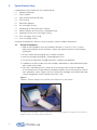
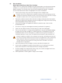
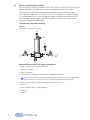
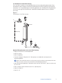
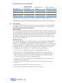
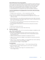
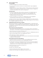
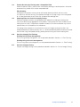
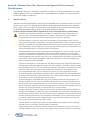
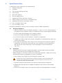
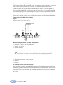
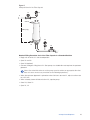
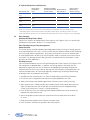
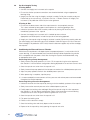
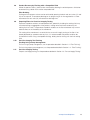
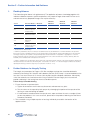
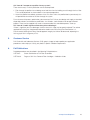
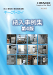
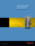
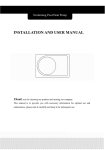
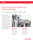
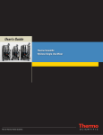
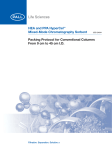
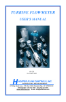
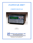
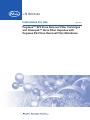
Instructions For Use
USD 2833
Pegasus™ SV4 Virus Removal Filter Cartridges
and Kleenpak™ Nova Filter Capsules with
Pegasus SV4 Virus Removal Filter Membrane
Contents
Introduction.......................................................................................................................3
Section A – Pegasus SV4 Virus Removal Filter Cartridges for use with
Pall Advanta Housings .....................................................................................................3
1. Specifications ...................................................................................................................3
2. Typical Process Steps ......................................................................................................4
2.1 Receipt of Equipment ..................................................................................................4
2.2 Filter Installation ............................................................................................................5
2.3 Filter Assembly Wetting and Filling ................................................................................6
2.4 Filter Flushing................................................................................................................8
2.5 Sterilization (Optional)....................................................................................................9
2.6 Pre-Use Integrity Testing ............................................................................................10
2.7 Conditioning the Filter and Process Filtration ..............................................................10
2.8 Product Recovery by Flushing with a Compatible Fluid ..............................................11
2.9 Preparing Filters for Post-Use Integrity Testing ............................................................11
2.10 Post-Use Integrity Test Flushing ................................................................................11
2.11 Post-Use Integrity Testing ........................................................................................11
Section B – Kleenpak Nova Filter Capsules with Pegasus SV4 Virus Removal
Filter Membrane .............................................................................................................12
1. Specifications .................................................................................................................12
2. Typical Process Steps ....................................................................................................13
2.1 Receipt of Equipment ................................................................................................13
2.2 Installation ..................................................................................................................13
2.3 Filter Assembly Wetting and Filling ..............................................................................14
2.4 Filter Flushing..............................................................................................................16
2.5 Sterilization (Optional)..................................................................................................17
2.6 Pre-Use Integrity Testing ............................................................................................18
2.7 Conditioning the Filter and Process Filtration ..............................................................18
2.8 Product Recovery by Flushing with a Compatible Fluid ..............................................19
2.9 Preparing Filters for Post-Use Integrity Testing ............................................................19
2.10 Post-Use Integrity Test Flushing ................................................................................19
2.11 Post-Use Integrity Testing ........................................................................................19
Section C – Further Information and Guidance ............................................................20
1. Flushing Volumes ...........................................................................................................20
2. Further Guidance for Integrity Testing ..........................................................................20
3. Filter Return Procedure..................................................................................................21
4. Frequently Asked Questions..........................................................................................21
5. Customer Service ...........................................................................................................23
6. Pall Publications .............................................................................................................23
2
Introduction
The following procedures must be followed for the installation of Pall® pharmaceutical-grade Pegasus
SV4 virus removal filter cartridges for use with Pall Advanta housings, and Kleenpak Nova filter capsules
with Pegasus SV4 Virus Removal Filter Membrane.
Pegasus SV4 filters are direct flow filters that remove viruses essentially by size exclusion. Due to the
small pore size required to remove viruses, these filters exhibit lower liquid flow characteristics when
compared to filters and capsules utilizing sterilizing-grade membranes. These flow rates may influence
several aspects of use including wetting and subsequent operation.
Pall also provides fully automated integrated virus filter systems that provide the highest level of process
safety and efficiency. These systems offer precise and consistent automated process steps for improved
process efficiency and reduced labor costs.
The instructions contained in the product documentation contain valuable information gained
by extensive experience and should be read thoroughly. It is important that all instructions are
carefully followed, and where appropriate, they should be incorporated into the end user’s
standard operating procedures. Where these procedures do not suit your needs, please contact
Pall or your local distributor before finalizing your system or process.
Use of the product in a manner other than in accordance with Pall’s current recommendations
may lead to injury or loss. Pall cannot accept liability for such injury or loss.
Section A – Pegasus SV4 Virus Removal Filter Cartridges for use with
Pall Advanta Housings
The following information is only intended as a guide. It contains a set of recommendations for a basic
mode of operation and is not intended to discuss all possible process variables. For more information
or technical support, see Section C.
1.
Specifications
Operation outside the specifications and with fluids incompatible with construction materials may cause
personal injury and result in damage to the equipment. Incompatible fluids are fluids which chemically
attack, soften, swell, stress attack or adversely affect the materials of construction. Please check the
datasheet and product label or contact Pall for further guidance if required.
European Directive 94/9/EC (ATEX) ‘Equipment For Use In Potentially Explosive Atmospheres’
Pall filter cartridges comply with the ATEX directive when installed in a compliant Pall filter
housing or assembly, but are not themselves required to be labelled with the ATEX marking.
Under the terms of the directive, filter cartridges are not considered to be equipment which is
capable of autonomous function, but may be thought of as components which are essential
to the operation of the equipment. As such, the conformity of the filter cartridges has been
assessed as an integral part of the overall assembly.
www.pall.com/biopharm
3
2.
Typical Process Steps
A typical process flow includes but may not be limited to:
2.1
Receipt of Equipment
2.2
Filter Installation
2.3
Filter Assembly Wetting and Filling
2.4
Filter Flushing
2.5
Sterilization (optional)
2.6
Pre-use Integrity Testing
2.7
Conditioning the Filter and Process Filtration
2.8
Product Recovery by Flushing with a Compatible Fluid
2.9
Preparing Filters for Post-Use Integrity Testing
2.10 Post-use Integrity Test Flushing
2.11 Post-use Integrity Testing
Ultimately, the procedures used must satisfy any process-specific validation requirements.
2.1
Receipt of Equipment
1. Store the filter cartridge in clean, dry conditions between 0 °C and 30 °C (86 °F) without
exposure to irradiation sources like direct sunlight, and wherever practical in the packaging
as delivered
2. DO NOT remove from packaging until just before installation
3. Check that the bag or packaging is undamaged prior to use
4. Ensure that the type of filter cartridge selected is suitable for the application
5. In addition to the part number, each filter cartridge is identified by a unique identification batch
and a unique serial number
6. Every filter is identified by a part number with lot and unique serial number also provided
as a two-dimensional (2D) bar code* for complete traceability of manufacturing history and for
user’s traceability system. Pegasus SV4 virus removal filter cartridges are manufactured under
a Quality Management System certified to ISO 9001:2008
Figure 1
Palltronic® Flowstar integrity test instrument and Palltronic bar code reader*
*The Palltronic Barcode Reader is ideal for use with Palltronic Flowstar filter integrity test instruments and can read and
interpret a variety of one-and two-dimensional barcodes.
4
2.2
Filter Installation
Single Open-ended Plug-in Style Filter Cartridges
Pegasus SV4 virus removal filter cartridges are high-quality products manufactured to exacting
standards. It is essential to take care when handling and installing them into filter housings.
Before installation,it is essential to verify that the filter cartridge type selected is suitable for
the fluid to be filtered and to follow the appropriate instructions listed below.
1.
Open the plastic bag, taking care not to damage the filter cartridge inside
Caution: Avoid use of sharp blades or pointed instruments that could damage the filter
cartridge and potentially damage the filter. Do not open bag by forcing the filter cartridge
through the sealed end as this can generate particulate contaminants
2.
To prevent accidental contamination of the filter cartridge, wherever practical wear gloves
and retain the open plastic bag around the filter cartridge when fitting into the filter housing.
Remove bag before closing the filter housing
3.
Certain filter cartridges are supplied with ‘bomb fin’ protective caps, these must be
removed before use
4.
Ensure that O-ring(s) are undamaged and correctly positioned in the groove(s)
5.
Check that the sealing surface on the filter housing is clean and undamaged
6.
To assist ease of fitting, it is strongly recommended that O-rings are lubricated by dipping
the open end of the filter cartridge in a suitable liquid which is compatible with the fluid
to be filtered. Water with the same quality as used for final rinsing of the installation is a
satisfactory lubricant in many cases. For advice on other lubricants, please contact Pall
Caution: Installation of double O-ring cartridges into housings: low boiling-point lubricants
(e.g. ethyl or isopropyl alcohol) must not be used if the installed filter is to be subsequently
steam sterilized or exposed to temperatures above the boiling point of the lubricant.
The high vapor pressures between the O-rings under these conditions can result in
damage to the O-ring adaptor
7.
Grip the outside of the filter cartridge as closely as possible to the open end
8.
Insert the filter cartridge with a gentle twisting motion to assist wetting of the surfaces.
Gently ease into place. Do not attempt to force the cartridge into position
9.
For filter cartridges with a bayonet lock fitting, finally twist the filter cartridge clockwise to
engage the retaining lugs within the filter head
10.
Where applicable, fit retaining plate or springs over cartridges
www.pall.com/biopharm
5
2.3
Filter Assembly Wetting and Filling
The first contact of the filter with process fluids, wetting agents, or flushing fluids is critical and
needs to be carefully controlled to ensure even and complete wetting at later stages.
Pall recommends that filling be implemented from bottom to top on a filter being held in a
vertical position, bubble-free, in a time not faster than 5 minutes for a 10 inch filter cartridge.
The standard wetting fluid is water. For large or complex assemblies please contact Pall for
recommended filling flow regimes. Typical filter installation schemes that will allow correct
wetting and filling are described below.
I. Pall Advanta T-Style Filter Housing
Figure 2
Pall Advanta T-Style Filter Housing
P1
Vent V3
P2
V1
V4
In
Out
Drain
V2
Nominal Filling Procedure for T-Style Configuration
• Begin with all valves in the closed position
• Open V1, V2 and V3
• Open V4 (optional)
• Start pump at a suitable flow rate to prime the upstream pipework
(Note: Care should be taken when setting the pump speed to achieve an appropriate
flow that does not cause unnecessary overshoot to the following operations)
• When fluid exits from V2, adjust the pump flow rate to 0.25 L/min
• Close V2
• When fluid exits from V3, stop the pump
• Close V3
• Open V4
6
II. Pall Advanta In-Line Filter Housing
For in-line filters installed in the standard orientation with the outlet pointing downwards, filling
from bottom to top will require the fluid to be admitted into the housing through the lower drain
connection. This is required during the initial filling operation only. Subsequent re-filling operations
can use the housing inlet connection but should be controlled to prevent excessive aeration
of the fluid.
Figure 3
Pall Advanta In-Line Filter Housing
P1
V1
In
Vent V3
(Filling only)
P2
Drain
V2
V4
Out
Nominal Filling Procedure for In-Line Filter Housing
• Begin with all valves in the closed position
• Open V2 and V3
• Open V4 (optional)
• Connect the bypass filling line to V2. Start pump at a suitable flow rate to prime the
upstream pipework
(Note: Care should be taken to set the pump speed to achieve an appropriate flow that
does not cause unnecessary overshoot to the following operations)
• When the upstream pipe work is primed or when fluid starts to enter V2, adjust to a flow rate
to 0.25 L/min
• When a steady stream of fluid exits from V3, stop the pump
• Close V3, Close V2
• Open V1, V4
www.pall.com/biopharm
7
III. Typical Filling Times and Flow Rates
Maximum Flow Rate
During Critical Filling
Period1 (L/min)
Minimum Filling Time
(minutes)
Approx. Critical Filling
Volume (drain to vent)2 (L)
254 mm
(10 in.)
0.25
5
1.30
508 mm
(20 in.)
0.25
10
2.58
762 mm
(30 in.)
0.25
15
3.85
Filter Cartridge Size
1 The flow rate necessary to provide an appropriate filling rate is dependant upon the installation geometry and may
need to account for volumes other than those that are filling as the fluid level is rising over the filter surface
2 Critical filling volume: Volume of fluid required to fill the filter and filter housing, excluding the volume not in direct
contact with the filter. Typically this is the volume between fluid flowing from V2 and V3 in Figures 2 and 3 during filling
2.4
Filter Flushing
The standard flushing fluid is water. Typical Flush Volumes for Pegasus SV4 virus removal filter
cartridges for use with Pall Advanta housings can be found in Section C: ‘Flushing Volumes’.
Filter Flushing Using a Pump Arrangement
Pump Selection
The chosen pump should be capable of providing approximately 3.5 bar g (50.8 psig) pressure
at the required process flow rate. It is also essential that flow and pressure do not pulsate during
the flushing and processing operations. Such pressure pulsations can have an adverse effect on
wetting effectiveness by forcing air into the filtration media. In extreme circumstances these
fluctuations may damage the filters being flushed. Pall recommends the Quattroflow™ series
of pumps for these applications.
Flushing Pressure
Pressure recommendations for the flushing of Pegasus SV4 filter cartridges are detailed below.
In general, any wetting regime is enhanced with the application of higher pressure with the
maximum acceptable pressure being limited by the maximum pressure claims for the filter or filter
housing. Both inlet pressure and back-pressure increase the effectiveness of the flushing regime
by compressing, dissolving and eliminating residual gas from the membrane construction.
1. Condition the filter as per Section 2.3: ‘Filter Assembly Wetting and Filling’
2. Ensure that all air is purged from the housing using the appropriate vent valve
3. Slowly increase the pump speed to generate an inlet pressure of 2.0 bar g (29 psig)
4. When the pressure is stable, partially close the downstream valve to apply back-pressure.
Adjust the back-pressure until the inlet pressure and back-pressure are approximately
3.5 bar g (50.8 psig) and 1.5 bar g (21.8 psig) respectively
5. Flush the filter for 10 minutes, adjusting pump speed and back-pressure to maintain the
required inlet and outlet pressure
6. After flushing open the back-pressure valve and wait for the outlet pressure to decay
to ~0 bar
7. Reduce the pump speed until the inlet pressure reads 0 bar
8. Drain the excess fluid from the upstream side of the filter housing
8
Filter Flushing Using a Pressure Arrangement
There are issues that must be considered when fluid is transferred using a pressurized vessel.
These include the dissolution of gas into the flushing and process fluids during the extended
pressurization of the reservoir during flushing. During the transfer of these fluids, pressure
changes can cause the dissolved gas to form micro-bubbles within the filtration media.
This may lead to localized partial non-wetting and subsequent integrity test failures.
It is recommended that this is evaluated at full scale as part of the process qualification.
To minimize the dissolution of gas, Pall recommends that the reservoir is pressurized for the
shortest possible period and is sized appropriately to minimize the fluid surface area available
for gas transfer.
1. Condition the filter as per Section 2.3: ‘Filter Assembly Wetting and Filling’
2. Ensure that all air is purged from the housing using the appropriate vent valve
3. Slowly increase the pressure on the wetting fluid reservoir to generate an inlet pressure of
1.5 bar g (21.8 psig)
4. When the fluid exits the system, partially close the back-pressure valve. Adjust the reservoir
pressure and backpressure valve to obtain approximately 3.5 bar g (50.8 psig) inlet pressure
and 1.5 bar g (21.8 psig) back-pressure
5. Flush the filter for 10 minutes adjusting the reservoir pressure and back-pressure valve
to maintain the inlet and outlet pressure
6. After flushing open the back-pressure valve and wait for the outlet pressure to decay
to ~0 bar
7. Reduce the reservoir pressure to 0 bar
8. Drain the excess fluid from the upstream side of the housing
2.5
Sterilization (Optional)
Unless specifically labelled, Pegasus SV4 virus removal filter cartridges are supplied non-sterile.
Steam in Place and Autoclaving
• Please refer to the appropriate Pall product information literature for products that can
be steam-sterilized in place or autoclaved and the maximum recommended cumulative
autoclave exposure time
• Autoclave sterilization procedures are detailed in Pall publication USTR 805
• Pegasus SV4 virus removal filter cartridges must be wetted with water prior to autoclaving
or steaming-in-place
• Pegasus SV4 virus removal filter cartridges must not be allowed to dry out after autoclaving
or steam-in-place to maintain water wet integrity testability
• Do not autoclave the cartridges in the bag supplied
Post-Sterilization
1. Condition the filter as described in Section 2.3: ‘Filter Assembly Wetting and Filling’
2. Flush the filter with 0.1 micron filtered (or equivalent) sterile DI water as described in
Section 2.4: ‘Filter Flushing’
3. Perform post-sterilization aseptic Integrity Test as described in Section 2.6:
‘Pre-use Integrity Testing’
www.pall.com/biopharm
9
2.6
Pre-Use Integrity Testing
If Testing Offline:
1. Connect the integrity test instrument to the filter housing
2. Ensure that all other upstream connections are closed or blanked using an appropriate
blanking fitting
3. Integrity test the filter using the integrity test data issued by Pall for the assembly under test.
Please refer to the user manual, ‘Instructions For Use – Palltronic Flowstar IV Integrity Test
Instrument’ (Pall publication USD 2594) for further guidance
If Testing In Situ:
1. Ensure that the downstream side of the filter housing remains at atmospheric pressure.
This is best achieved by being open to atmosphere via a sterilizing-grade gas filter
2. Isolate the upstream side of the assembly under test by closing the necessary valves
immediately upstream of the filter housing
3. Connect the integrity test instrument to this isolated upstream volume. Appropriate
connection points include the filter housing, or connecting pipework
4. Integrity test the filter using the integrity test data issued by Pall for the assembly under test
For more integrity test information consult the Validation Guide for Pegasus SV4 Virus Removal
Filter Cartridges (Pall publication USTR 2839).
2.7
Conditioning the Filter and Process Filtration
While the exact requirements will depend upon the proposed process, in conjunction with full
system draining, it is recommended that the residual wetting fluid is displaced using a buffer that
is compatible with the process fluid. After flushing the filter housing should be drained using an
appropriate drain valve.
Processing Using a Pump Arrangement
1. Slowly increase the pump speed to 0.25 L/min. Fill the housing using the valve sequences
from Section 2.3 for the relevant configuration allowing displaced air to vent from the vent valve
2. Close the housing vent valve when the housing is full
3. Slowly increase the pump speed until the inlet pressure reaches the validated process pressure
4. Adjust the pump speed to maintain the validated process pressure
5. When processing is complete, stop the pump
6. It is recommended that measurements of time, pressure and volume processed are recorded
throughout the filtration operation
Processing Using a Pressure Arrangement
1. Isolate the reservoir from the filters by closing a valve immediately upstream of the filters
2. Slowly increase the reservoir pressure to the validated process pressure
3. Partially open the isolating valve and begin filling of the housing using the valve sequences
from Section 2.3 for the relevant configuration. Adjust the reservoir pressure and isolating
valve position to ensure a filling flow rate of no greater than 0.25 L/min
4. Close the housing vent valve when the housing is full
5. Fully open the isolating valve
6. Process until the reservoir is empty
7. Close the isolating valve and slowly depressurize the reservoir
8. Depressurize the housing by slowly opening the housing vent valve
10
2.8
Product Recovery by Flushing with a Compatible Fluid
Where the process allows, yields can be maximized by allowing the residual process fluid to be
recovered using a buffer flush or other compatible fluid.
Filter Draining
Drainage of the upstream volume can be achieved by opening the drain and vent valves
(V2 and V3) on the filter housing. To accelerate drainage an air purge using an air line regulated
to <0.5 bar attached to the vent valve (V3) will reduce the drainage time.
2.9
Preparing Filters for Post-Use Integrity Testing
Exposure of product residues to incompatible fluids, potentially including the wetting fluid,
may cause denaturing or aggregation of the product, making removal of these residues by the
wetting flush less likely. The presence of product residues on the filter membrane may have an
adverse effect on the wettability of the membrane.
Full wetting of the membrane is essential for the successful integrity testing of the filter. If not
already displaced by a product recovery flush, it is recommended that product residues be flushed
from the filter using a compatible fluid (e.g. buffer) prior to flushing with the final wetting fluid.
2.10
Post-Use Integrity Test Flushing
Flushing Using a Pump Arrangement
To flush using a pump arrangement, use the procedure detailed in Section 2.4: ‘Filter Flushing’.
Flushing Using a Pressure Arrangement
To flush using a pressure arrangement, use the procedure detailed in Section 2.4: ‘Filter Flushing’.
2.11
Post-Use Integrity Testing
For post-use integrity testing, use the procedures detailed in Section 2.6: ‘Pre-use Integrity Testing’.
www.pall.com/biopharm
11
Section B – Kleenpak Nova Filter Capsules with Pegasus SV4 Virus Removal
Filter Membrane
The following information is intended as a guide only. It contains a set of recommendations for a basic
mode of operation and is not intended to discuss all possible process variables. For more information
or technical support, see Section C.
1.
Specifications
Operation outside the specifications and with fluids incompatible with construction materials may cause
personal injury and result in damage to the equipment. Incompatible fluids are fluids which chemically
attack, soften, swell, stress attack or adversely affect the materials of construction. Please refer check
the datasheet and product label or contact Pall for further guidance if required.
European Directive 94/9/EC (ATEX) ‘Equipment for Use in Potentially Explosive Atmospheres’
Installation and maintenance should be undertaken by a competent person. National and local
codes of practice, environmental regulations and Health & Safety directives must be adhered
to and take precedence over any stated or implied practices within this document.
For fluids having low conductivity, there exists the possibility of the generation of static electricity
during use with all polymeric components. This could potentially lead to a static electricity discharge
resulting in the ignition of a potentially explosive atmosphere where such an atmosphere is present.
These Pall products are not suitable for use with such low conductivity fluids in an environment that
includes flammable liquids or a potentially explosive atmosphere.
Where flammable or reactive fluids are being processed through a Pall capsule assembly, the user
should ensure that spillages during filling, venting, depressurizing, draining and capsule change
operations are minimized, contained or directed to a safe area. In particular, the user should ensure
that flammable fluids are not exposed to surfaces at a temperature that may ignite the fluid, and that
reactive fluids cannot contact incompatible materials that may lead to reactions generating heat,
flame or that are otherwise undesirable.
Pall capsule assemblies do not generate heat, but during the processing of high temperature fluids,
including steam sterilization operations and process upset conditions, it will take on the temperature
of the fluid being processed. The user should ensure that this temperature is acceptable for the area
in which the filter is to be operated, or that suitable protective measures are employed. When
processing flammable fluids, the user should ensure that any air is fully purged from within the
assembly during filling and subsequent operation to prevent the formation of a potentially flammable
or explosive vapor/air mixture inside the equipment. This can be achieved through careful venting of
the assembly or system as detailed in the user instructions.
To prevent damage or degradation which may result in leakage of fluids from this equipment it is
imperative that the end user check the suitability of all materials of construction (including seals on
the connections where appropriate) with the process fluid and conditions. The user should ensure
that the assembly is regularly inspected for damage and leaks, which should be promptly corrected,
and that seals (where appropriate) are renewed after every capsule change.
Leakage of flammable or reactive fluids from this assembly, arising through incorrect installation or
damage to the equipment (including any seals), may generate a source of ignition if flammable fluids
are exposed to a heated surface, or if reactive fluids contact incompatible materials that may lead to
reactions generating heat, flame or that are otherwise undesirable. The user should ensure that the
assembly is regularly inspected for damage and leaks, which should be promptly corrected, and
that any seals are renewed after every filter change.
The user should ensure that these products are protected from foreseeable mechanical damage
that might cause such leakage, including impact and abrasion.
Regular cleaning with an anti-static material is required to avoid the build up of dust on the filter
assembly. Should you have any queries – then please contact your local Pall office or distributor.
12
2.
Typical Process Steps
A typical process flow includes but may not be limited to:
2.1
Receipt of Equipment
2.2
Installation
2.3
Filter Assembly Wetting and Filling
2.4
Filter Flushing
2.5
Sterilization (optional)
2.6
Pre-use Integrity Testing
2.7
Conditioning the Filter and Process Filtration
2.8
Product Recovery by Flushing with a Compatible Fluid
2.9
Preparing Filters for Post-Use Integrity Testing
2.10 Post-use Integrity Test Flushing
2.11 Post-use Integrity Testing
Ultimately, the procedures used must satisfy any process-specific validation requirements.
2.1
Receipt of Equipment
1. Store the capsule in clean, dry conditions between 0 °C and 30 °C (86 °F) without exposure
to irradiation sources like direct sunlight, and wherever practical in the packaging as delivered
2. DO NOT remove from packaging until just before installation
3. Check that the bag or packaging is undamaged prior to use
4. Ensure that the type of capsule selected is suitable for the application
5. In addition to the part number, each capsule is identified by a unique identification batch and
a unique serial number
6. Every capsule is identified by a part number with lot and unique serial number for complete
traceability of manufacturing history and for the user’s traceability system. Kleenpak Nova
filter capsules are manufactured under a Quality Management System certified to ISO
9001:2008.
2.2
Installation
Kleenpak Nova filter capsules are high-quality products manufactured to exacting standards.
It is essential to take care when handling and installing them.
Before installation, it is essential to verify that the capsule type selected is suitable for the fluid to
be filtered and to follow the appropriate instructions listed below.
1. Open the plastic bag, taking care not to damage the capsule inside
Caution: Avoid use of sharp blades or pointed instruments that could damage the
capsule. Do not open bag by forcing the capsule through the sealed end as this
can generate particulate contaminants
2. To prevent accidental contamination of the capsule, wherever practical wear gloves
3. Kleenpak Nova filter capsules are supplied with protective caps, these must be removed
before use
4. Check that the sealing surfaces on the capsule are clean and undamaged prior to installation
www.pall.com/biopharm
13
2.3
Filter Assembly Wetting and Filling
The first contact of the filter with process fluids, wetting agents, or flushing fluids is critical and
needs to be carefully controlled to ensure even and complete wetting at later stages.
Pall recommends that filling be implemented from bottom to top on a filter being held in a
vertical position, bubble-free, in a time not faster than 5 minutes for a 10 inch filter cartridge.
The standard wetting fluid is water. For large, or complex assemblies please contact Pall for
recommended filling flow regimes.
Typical filter installation schemes that will allow correct wetting and filling are described below.
I. Kleenpak Nova T-Style Filter Capsule
Figure 4
Kleenpak Nova T-Style Filter Capsule
Vent V3
P1
P2
V1
V4
In
Out
Drain
V2
Nominal Filling Procedure for T-Style Configuration
• Begin with all valves in the closed position
• Open V1, V2 and V3
• Open V4 (optional)
• Start pump at a suitable flowrate to prime the upstream pipework
(Note: Care should be taken when setting the pump speed to achieve an appropriate
flow that does not cause unnecessary overshoot to the following operations.)
• When fluid exits from V2, adjust the pump flow rate to 0.25 L/min
• Close V2
• When fluid exits from V3, stop the pump
• Close V3
• Open V4
II. Kleenpak Nova In-Line Filter Capsule
For in-line filters installed in the standard orientation with the outlet pointing downwards, filling
from bottom to top will require the fluid to be admitted into the capsule through the lower drain
connection. This is required during the initial filling operation only. Subsequent re-filling operations
can use the capsule inlet connection but should be controlled to prevent excessive aeration
of the fluid.
14
Figure 5
Kleenpak Nova In-Line Filter Capsule
P1
V1
In
Vent V3
(Filling only)
P2
Drain
V2
V4
Out
Nominal Filling Procedure for In-Line Filter Capsule in a Standard Position
• Begin with all valves is in the closed position
• Open V2 and V3
• Open V4 (optional)
• Connect the bypass filling line to V2. Start pump at a suitable flow rate to prime the upstream
pipework
(Note: Care should be taken to set the pump speed to achieve an appropriate flow that
does not cause unnecessary overshoot to the following operations.)
• When the upstream pipe work is primed or when fluid starts to enter V2, adjust to a flow rate
to 0.25 L/min
• When a steady stream of fluid exits from V3, stop the pump
• Close V3, Close V2
• Open V1, V4
www.pall.com/biopharm
15
III. Typical Filling Times and Flowrates
Filter Capsule
Part Number
Code
Maximum Flow Rate
During Critical Filling Minimum Filling
Period1 (L/min)
Time (minutes)
Approx. Critical
Filling Volume
(drain to vent)2 (L)
25 mm
(1 in.)
NP1L
0.25
2
0.45
254 mm
(10 in.)
NT6
NP6L
0.25
5
1.30
508 mm
(20 in.)
NT7
NP7L
0.25
10
2.58
762 mm
(30 in.)
NT8
NP8L
0.25
15
3.85
Filter Capsule Size
1 The flow rate necessary to provide an appropriate filling rate is dependant upon the installation geometry and may
need to account for volumes other than those that are filling as the fluid level is rising over the filter surface
2 Critical filling volume: Volume of fluid required to fill the filter and filter capsule, excluding the volume not in direct
contact with the filter. Typically this is the volume between fluid flowing from V2 and V3 in Figures 4 and 5 during filling.
2.4
Filter Flushing
Standard Flushing Fluid is Water
Typical Flush Volumes for Kleenpak Nova Filter Capsules with Pegasus SV4 virus removal filter
membrane can be found in Section C: ‘Flushing Volumes’.
Filter Flushing Using a Pump Arrangement
Pump Selection
The chosen pump should be capable of providing approximately 3.5 bar g (50.8 psig) pressure
at the required process flow rate. It is also essential that flow and pressure do not pulsate during
the flushing and processing operations. Such pressure pulsations can have an adverse effect
on wetting effectiveness by forcing air into the filtration media. In extreme circumstances these
fluctuations may damage the filters being flushed. Pall recommends the Quattroflow™ series
of pumps for these applications.
Flushing Pressure
Pressure recommendations for the flushing of Kleenpak Nova Filter Capsules with Pegasus SV4
filter membrane are detailed below. In general, any wetting regime is enhanced with the
application of higher pressure with the maximum acceptable pressure being limited by the
maximum pressure claims for the filter or filter capsule. Both inlet pressure and back-pressure
increase the effectiveness of the flushing regime by compressing, dissolving and eliminating
residual gas from the membrane construction.
1. Condition the filter as per Section 2.3: ‘Filter Assembly Wetting And Filling Procedures’
2. Ensure that all air is purged from the capsule using the appropriate vent valve
3. Slowly increase the pump speed to generate an inlet pressure of 2.0 bar g (29 psig)
4. When the pressure is stable, partially close the downstream valve to apply back-pressure.
Adjust the back-pressure until the inlet pressure and back-pressure are approximately
3.5 bar g (50.8 psig) and 1.5 bar g (21.8 psig) respectively
5. Flush the filter for 10 minutes, adjusting pump speed and back-pressure to maintain the
required inlet and outlet pressure
6. After flushing open the back-pressure valve and wait for the outlet pressure to decay
to ~0 bar
7. Reduce the pump speed until the inlet pressure reads 0 bar
8. Drain the excess fluid from the upstream side of the capsule
16
Filter Flushing Using a Pressure Arrangement
There are issues that must be considered when fluid is transferred using a pressurized vessel.
These include the dissolution of gas into the flushing and process fluids during the extended
pressurization of the reservoir during flushing. During the transfer of these fluids, pressure
changes can cause the dissolved gas to form micro-bubbles within the filtration media. This may
lead to localized partial non-wetting and subsequent integrity test failures. It is recommended
that this is evaluated at full scale as part of the process qualification.
To minimize the dissolution of gas, Pall recommends that the reservoir is pressurized for the
shortest possible period and is sized appropriately to minimize the fluid surface area available
for gas transfer.
1. Condition the filter as per Section 2.3: ‘Filter Assembly Wetting And Filling’
2. Ensure that all air is purged from the capsule using the appropriate vent valve
3. Slowly increase the pressure on the wetting fluid reservoir to generate an inlet pressure of
1.5 bar g (21.8 psig)
4. When the fluid exits the system, partially close the back-pressure valve. Adjust the reservoir
pressure and backpressure valve to obtain approximately 3.5 bar g (50.8 psig) inlet pressure
and 1.5 bar g (21.8 psig) back-pressure
5. Flush the filter for 10 minutes adjusting the reservoir pressure and back-pressure valve to
maintain the inlet and outlet pressure
6. After flushing open the back-pressure valve and wait for the outlet pressure to decay
to ~0 bar
7. Reduce the reservoir pressure to 0 bar
8. Drain the excess fluid from the upstream side of the capsule
2.5
Sterilization (Optional)
Unless specifically labelled, Kleenpak Nova Filter Capsules with Pegasus SV4 Virus Removal
Filter Membrane are supplied non-sterile.
Kleenpak Nova Filter Capsules with Pegasus SV4 Virus Removal Filter Membrane
MUST NOT be Steam Sterilized
Sterilization by Autoclaving
• Please refer to the appropriate Pall product information literature for products that can
be autoclaved and the maximum recommended cumulative autoclave exposure time
• Autoclave sterilization procedures are detailed in Pall publication USTR 805
• Pegasus SV4 filter cartridges must be wetted with water prior to autoclaving
• Pegasus SV4 filter cartridges must not be allowed to dry out after autoclaving
in order to maintain water wet integrity testability
• Do not autoclave capsules in the bag supplied
Post Sterilization
1. Condition the filter as described in Section 2.3: ‘Filter Assembly Wetting And Filling’
2. Flush the filter with 0.1 micron filtered (or equivalent) sterile DI water as described in
Section 2.4: ‘Filter Flushing’
3. Perform post-sterilization aseptic Integrity Test as described in Section 2.6:
‘Pre-use Integrity Testing’
www.pall.com/biopharm
17
2.6
Pre-Use Integrity Testing
If Testing Offline:
1. Connect the integrity test instrument to the capsule
2. Ensure that all other upstream connections are closed or blanked using an appropriate
blanking fitting
3. Integrity test the filter using the integrity test data issued by Pall for the assembly under test.
Please refer to the user manual, ‘Instructions For Use – Palltronic Flowstar IV Integrity Test
Instrument’ (Pall publication USD2594) for further guidance
If Testing In Situ:
1. Ensure that the downstream side of the capsule remains at atmospheric pressure.
This is best achieved by being open to atmosphere via a sterilizing grade gas filter
2. Isolate the upstream side of the assembly under test by closing the necessary valves
immediately upstream of the capsule
3. Connect the integrity test instrument to this isolated upstream volume.
Appropriate connection points include the capsule or connecting pipework
4. Integrity test the capsule using the integrity test data issued by Pall for the assembly under test
For more integrity test information consult the Validation Guide for Pegasus SV4 Virus Removal
Filter Cartridges (Pall publication USTR 2839). Note this document applies only to filter cartridges,
not capsules.
2.7
Conditioning the Filter and Process Filtration
While the exact requirements will depend upon the proposed process, in conjunction with full
system draining, it is recommended that the residual wetting fluid be displaced using a buffer
that is compatible with the process fluid. After flushing the capsule should be drained using
an appropriate drain valve.
Processing Using a Pump Arrangement
1. Slowly increase the pump speed to 0.25 L/min. Fill the capsule using the valve sequences
from Section 2.3 for the relevant configuration allowing displaced air to vent from the vent valve
2. Close the capsule vent valve when the capsule is full
3. Slowly increase the pump speed until the inlet pressure reaches the validated process pressure
4. Adjust the pump speed to maintain the validated process pressure
5. When processing is complete, stop the pump
6. It is recommended that measurements of time, pressure and volume processed are recorded
throughout the filtration operation
Processing Using a Pressure Arrangement
1. Isolate the reservoir from the capsule by closing a valve immediately upstream of the capsule
2. Slowly increase the reservoir pressure to the validated process pressure
3. Partially open the isolating valve and begin filling of the capsule using the valve sequences
from Section 2.3 for the relevant configuration. Adjust the reservoir pressure and isolating
valve position to ensure a filling flow rate of no greater than 0.25 L/min
4. Close the capsule vent valve when the capsule is full
5. Fully open the isolating valve
6. Process until the reservoir is empty
7. Close the isolating valve and slowly depressurize the reservoir
8. Depressurize the capsule by slowly opening the capsule vent valve
18
2.8
Product Recovery by Flushing with a Compatible Fluid
Where the process allows, yields can be maximized by allowing the residual process fluid to be
recovered using a buffer flush or other compatible fluid.
Filter Draining
Drainage of the upstream volume can be achieved by opening the drain and vent valves (V2 and
V3) on the capsule. To accelerate drainage an air purge using an air line regulated to <0.5 bar
attached to the vent valve (V3) will reduce the drainage time.
2.9
Preparing Filters for Post-Use Integrity Testing
Exposure of product residues to incompatible fluids, potentially including the wetting fluid, may
cause denaturing or aggregation of the product, making removal of these residues by the
wetting flush less likely. The presence of product residues on the filter membrane may have an
adverse effect on the wettability of the membrane.
Full wetting of the membrane is essential for the successful integrity testing of the filter. If not
already displaced by a product recovery flush, it is recommended that product residues be
flushed from the filter using a compatible fluid (e.g. buffer) prior to flushing with the final wetting
fluid.
2.10
Post-Use Integrity Test Flushing
Flushing Using a Pump Arrangement
To flush using a pump arrangement, use the procedure detailed in Section 2.4: ‘Filter Flushing’.
To flush using a pressure arrangement, use the procedure detailed in Section 2.4: ‘Filter Flushing’.
2.11
Post-Use Integrity Testing
For post-use integrity testing, use the procedures detailed in: Section 2.6: ‘Pre-use Integrity Testing’.
www.pall.com/biopharm
19
Section C – Further Information And Guidance
1.
Flushing Volumes
The information given above is for guidance only. The application of process knowledge together with
individual validation or process specific requirements may require changes to be made. Pall can assist
and comment on any proposed changes that may be necessary.
Filter Part Number
NP1USV4
AB1USV4
NP6USV4
AB2USV4
NP7USV4
AB3USV4
NP8USV4
Typical Filter Area
0.25 m²
2.25 m²
4.5 m²
6.75 m²
Sections A & B
2.4
Typical water flush
volume for pre-use
integrity testing¹
1L
10 L
20 L
30 L
Sections A & B
2.7
Typical pre-use
buffer flush volume2
0.1 L
1L
2L
3L
Sections A & B
2.9
Typical post-use
buffer flush
volume2,3
0.1 L
1L
2L
3L
Sections A & B
2.10
Typical water flush
1L
volume for post-use
integrity testing³
10 L
20 L
30 L
Section
¹ See Section 2.4: ‘Filter Flushing’
² If dilution is problematic, the pre-use and post-use buffer flushes may be eliminated. It is however advisable to incorporate a
flush at these stages to minimize product losses through absorption of fluid retention. Flushing with buffer prior to the water flush
for integrity testing may be required to avoid potential product residue interactions. Precipitation or aggregation as a result of
product interactions with the water may cause localised alterations to the surface characteristics and may adversely affect the
wettability of the membrane with water (Sections A or B 2.7).
³ If there is significant post-use blockage, the flow rate at this stage may be greatly reduced. The volume required for flushing may
therefore be reduced to avoid excessive flushing time. See Sections A or B 2.9 – 2.11. Should integrity test failures be observed,
repeating the flushing cycle at this stage may assist (Sections A or B 2.9 – 2.11).
2.
Further Guidance for Integrity Testing
The integrity test parameters for Pegasus SV4 filter cartridges and capsules should be obtained in
advance by contacting Pall’s Scientific and Laboratory Services (SLS) Group. It is recommended that the
test time is set to a minimum of 15 minutes (900 seconds) to allow complete stabilization. Alternatively,
use of the automatic test time feature when using a Palltronic Flowstar integrity test instrument will
provide a reduction in the testing time when test conditions permit.
Failure Analysis/Troubleshooting
1. Ensure there are no upstream leaks:
a. Tighten all connections and if necessary disconnect and reconnect any joints
b. Test the valves on the capsule by leak spray or by submerging that portion of the capsule or filter
housing in water and looking for bubbles
c. If hardware leaks are observed on the capsule vents, open and close the vents a number of times
to solve the problem, if this is not successful, please return the products following the Filter Return
Procedure (see below)
2. Test assemblies using multiple capsules or housings individually to establish the location of the
apparent failure
20
3. Ensure environmental temperature is stable and the filter is not exposed to drafts or radiant heat.
If stability problems are encountered, shield the filter under test and the connecting tubing.
This can be accomplished by:
a. insulating the test tubing with additional sleeving
b. covering the filter and tubing with a suitable cover, or
c. placing the entire assembly in a closed-off fume cupboard or isolator
4. If stability problems still occur, the filter assembly may be immersed in water (at room temperature)
and tested, but it is essential that water is not allowed to enter the outlet of the filter capsule
5. Retesting
a. If points 1– 3 have been checked, and apparent integrity test failures are observed, repeat the
flushing cycle. PDA Technical Report No. 41, Virus Filtration states:
“6.4 Failure Analysis/Troubleshooting – If a virus filter fails an integrity test it could be damaged,
but there may be other causes for the failure. Any investigation of filter failure or retesting should
be described in a standard operating procedure. Part of the investigation should distinguish
between filter damage and possible test problems or artifacts.” To confirm corrective action,
in the case of Forward/Diffusion, Pressure Hold/Decay and Leak Tests, re-wet the filter according
to the specifications and repeat the test. If the filter integrity test fails again, the Forward/Diffusion,
Pressure Hold/Decay or Leak Tests may be performed in a lower-surface-tension reference fluid
(where specified by the filter manufacturer) to assess filter wettability changes independent of
filter integrity.
3.
Filter Return Procedure
In the event of having to return a filter for further evaluation, please contact your local sales
representative.
1. Please ensure that a completed Material Safety Data Sheet accompanies any returned filter.
2. Please supply as much information as possible regarding the filter use and any tests performed.
4.
Frequently Asked Questions
Q1: Can I flush and process using a pressure vessel or do I need a pump?
Both methods are acceptable although there are practical considerations. Any pump should be chosen
to supply a controllable and constant pressure. Where processing is performed under defined flow
conditions, it is essential that the pressure is monitored at all times and the maximum pressure
specifications or validated flow rates are not exceeded. Blockage of the filters during filtration will lead
to an increase in the differential pressure at the set flow rate therefore pressure needs to be constantly
monitored and the pump adjusted to prevent over pressurization of the system.
Filtration using a pressurized vessel can drive the fluid through the filter under a constant pressure of
up to 4.5 bard (65 psid). Using this arrangement supervision can be kept to a minimum, and where
blockage does occur the flow rate will simply decline. It is recommended that the process flow rate
be monitored using this technique.
Pressurization of fluid over prolonged periods can increase the amount of dissolved gas in the process
fluid. Natural pressure changes across the filtration media may cause the fluid to degas, potentially
forming trapped air bubbles within the filtration media. These bubbles may adversely affect the
observed flow rate and wetting of the filters.
Pall recommends the Quattroflow series of pump for medium to large-scale processes. These include
1 inch Kleenpak Nova filter capsules and larger.
www.pall.com/biopharm
21
Q2: How do you recommend flushing the filter prior to integrity testing?
Ways to set up the flushing system are shown in Figures 2 to 5 with flushing procedures contained in
Sections A and B 2.3 and 2.4. In each instance, a pressure of 3.5 bar (50.8 psi) should be generated
upstream, with the downstream valve partially closed to provide a back-pressure of 1.5 bar (21.8 psi)
throughout the duration of the flushing. It is highly recommended that the flow rate be monitored and
recorded during filling and flushing to document adherence to the filling and flushing recommendations
and any procedures derived from this guide.
Q3: Does my process require any prefiltration?
One of the key advantages of Pegasus SV4 filters is that they can tolerate a higher level of filter plugging
species, and their constant pressure/flux capabilities can handle more complex or concentrated feeds.
Therefore Pegasus SV4 filters require less extensive, less complex prefiltration minimising the risk of
premature fouling and flux decay as compared to other virus filters.
Each process and its associated contaminant profile are different and where high levels of contaminants
are present, further protection of Pegasus SV4 filters may be required. If flow decays are high, an
additional pre-filter (see table 3) should be considered. Where flux decay is <20%, the process is unlikely
to benefit from an additional pre-filter. Where flux decay is >50%, a pre-filter is likely to make the process
more economical.
For the process fluid it is recommended that a filterability assessment be performed on a representative
fluid to establish the likely throughput and degree of blockage of the intended filtration system.
Prefiltration may significantly increase the life of the intended virus filter or reduce the process time by
minimizing the reduction in flow rate associated with filter blockage.
Prefiltration is also highly recommended if there is any storage of the process feed prior to the virus
filtration. Even if 0.2 μm or 0.1 μm filtration prior to storage was performed, there is potential for (re-)
aggregation to occur, which may have a detrimental effect on the life of the virus filter.
Some typical prefilter recommendations can be seen below.
Table 3
Prefilter Recommendations
Second Pre-filter
(optional*)
Market
Process Fluid
First Pre-filter
General Market
Typical combination
for many fluids
Fluorodyne II DJL
Fluorodyne EX EDT
Not required
Pegasus SV4
Ultipor VF DV20
Biotech Market
Low fouling fluids
such as monoclonal
antibodies after
purification by
chromatography
Supor® ECV
Supor EKV
Supor EBV
Ultipor® N66 NF
Not required
Pegasus SV4
Ultipor VF DV20
Plasma Market
Typical combination for
plasma Fractionation
Supor ECV
Supor EKV
Supor EBV
Ultipor N66 NF
Fluorodyne EX EDF
®
Ultipor VF DVD
Pegasus ULV6
Ultipor VF DV50
* for fine particles or aggregates < 0.1 µm a second prefilter might make the process more economical
22
Final Filter
Pegasus SV4
Ultipor VF DV20
Q4: How do I incorporate a prefilter into my system?
There are two ways in which prefiltration can be accomplished.
1. Filter through the prefilter into a holding vessel and then from the holding vessel through the virus filter.
This can be performed as shown above in two separate operations
2. Attach the prefilter immediately upstream of the virus filter. Unless the prefilter blocks prematurely, this
will provide little restriction to the flow through the system
For assistance with process optimization, please contact Pall. Pall can also design and supply customized
disposable solutions to facilitate the prefiltration, virus filtration, sterile filtration and storage of filtered
product. These can be supplied at all scales to accommodate fast and reliable process scale-up.
Q5: How do I handle significant flow decay due to blockage?
If there is significant post-use blockage, the flow rate at this stage may be greatly reduced. The volume
required for flushing may therefore be reduced to avoid excessive flushing time. See Section 2.3:
Filter Assembly Wetting and Filling. Should apparent integrity test failures be observed, repeating the
flushing cycle at this stage may assist.
5.
Customer Service
Pall’s Scientific and Laboratory Services (SLS) group is happy to help expedite your application
procedures and to help you satisfy your process-specific validation requirements.
6.
Pall Publications
Detailed procedures are described in the following Pall publications:
USTR805:
Steam Sterilization of Pall Filter Assemblies
USTR2839:
Pegasus SV4 Virus Removal Filter Cartridges – Validation Guide
www.pall.com/biopharm
23
Visit us on the Web at www.pall.com/biopharm
E-mail us at [email protected]
Corporate Headquarters
Port Washington, NY, USA
+1 800 717 7255 toll free (USA)
+1 516 484 5400 phone
[email protected] e-mail
European Headquarters
Fribourg, Switzerland
+41 (0)26 350 53 00 phone
[email protected] e-mail
Asia-Pacific Headquarters
Singapore
+65 6389 6500 phone
[email protected] e-mail
International Offices
Pall Corporation has offices and plants throughout the world in locations such as: Argentina, Australia, Austria, Belgium,
Brazil, Canada, China, France, Germany, India, Indonesia, Ireland, Italy, Japan, Korea, Malaysia, Mexico,
the Netherlands, New Zealand, Norway, Poland, Puerto Rico, Russia, Singapore, South Africa, Spain, Sweden,
Switzerland, Taiwan, Thailand, the United Kingdom, the United States, and Venezuela. Distributors in all major
industrial areas of the world. To locate the Pall office or distributor nearest you, visit www.pall.com/contact.
The information provided in this literature was reviewed for accuracy at the time of publication. Product data may
be subject to change without notice. For current information consult your local Pall distributor or contact Pall directly.
© 2013, Pall Corporation. Pall,
, Pegasus, Kleenpak, Pall Advanta, Palltronic, Fluorodyne, Ultipor and Supor
are trademarks of Pall Corporation. ® indicates a trademark registered in the USA and TM indicates an unregistered
trademark. Quattroflow is a trademark of Pump Solutions Group. Filtration.Separation.Solution is a service mark
of Pall Corporation.
1/13, PDF, GN12.5041, FP01391
USD 2833