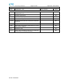
1
Ref. Certif. No. KR-KETI1926 IEC SYSTEM FOR MUTUAL RECOGNITION OF TEST CERTIFICATES FOR ELECTRICAL EQUIPMENT (IECEE) CB SCHEME SYSTEME CEI D’ACCEPTATION MUTUELLE DE CERTIFICATS D’ESSAIS DES EQUIPEMENTS ELECTRIQUES (IECEE) METHODE OC CB TEST CERTIFICATE Product Produit Name and address of the applicant Nom et adresse du demandeur Name and address of the manufacturer Nom et adresse du fabricant Name and address of the factory Nom et adresse de l’usine Note: When more than one factory, please report on page 2 Note: Lorsque il y plus d'une usine, veuillez utiliser la 2ème page CERTIFICAT D’ESSAI OC Video Recorder SHENZHEN ANKO TECH CO., LTD. NO. A1514, YUANZHENG INDUSTRIAL PARK, WUHE DADAO BEI, BANTIAN, LONGGANG ZONE, SHENZHEN CITY, CHINA SHENZHEN ANKO TECH CO., LTD. NO. A1514, YUANZHENG INDUSTRIAL PARK, WUHE DADAO BEI, BANTIAN, LONGGANG ZONE, SHENZHEN CITY, CHINA SHENZHEN ANKO TECH CO., LTD. NO. A1514, YUANZHENG INDUSTRIAL PARK, WUHE DADAO BEI, BANTIAN, LONGGANG ZONE, SHENZHEN CITY, CHINA Additional Information on page 2 Ratings and principal characteristics Valeurs nominales et caractéristiques principales DC 12V, 5A for 5816 (See page 2 For details) Trademark (if any) Marque de fabrique (si elle existe) ANKO Type of Manufacturer's Testing Laboratories used Type de programme du laboratoire d'essais constructeur Model / Type Ref. Ref. De type Additional information (if necessary may also be reported on page 2) Les informations complémentaires (si nécessaire,, peuvent être indiqués sur la 2ème page A sample of the product was tested and found to be in conformity with IEC Un échantillon de ce produit a été essayé et a été considéré conforme à laCEI As shown in the Test Report Ref. No. which forms part of this Certificate Comme indiqué dans le Rapport d’essais numéro de référence qui constitue partie de ce Certificat 5616, 5808, 5404, 5832, 5816, 6204, 6209, 6216, 6225, 6232 Additional Information on page 2 IEC 60065:2001 (Seventh Edition) + A1:2005 + A2:2010 W14-65-007 This CB Test Certificate is issued by the National Certification Body Ce Certificat d’essai OC est établi par l’OrganismeNational de Certification Korea Testing Certification (KTC) 24, 1gil, Sebang-Cheon, Gunpo-City, Gyeonggi-Do, 435-862, KOREA, REPUBLIC OF Date: 2014. 01. 27 Issued 2009-03 Signature:Seung-In Yang 1/2 Ref. Certif. No. KR-KETI1926 Ratings : Model 5616 5808 5404 5832 5816 6204 6209 6216 6225 6232 Rating DC 12V, 4A DC 12V, 3A DC 12V, 3A DC 12V, 6A DC 12V, 5A DC 12V, 3A DC 12V, 4A DC 12V, 5A DC 12V, 5A DC 12V, 6A Video input channel 16 8 4 32 16 4 9 16 25 32 Additional information (if necessary) Information complémentaire (si nécessaire) Korea Testing Certification (KTC) 24, 1gil, Sebang-Cheon, Gunpo-City, Gyeonggi-Do, 435-862, KOREA, REPUBLIC OF Date: 2014 01.27 Issued 2009-03 Signature:Seung-In Yang 2/2 Test Report issued under the responsibility of: Korea Testing Certification TEST REPORT IEC 60065 Audio, video and similar electronic apparatus - Safety requirements Report Number. .............................. : W14-65-007 Date of issue ................................... : 2014-01-25 Total number of pages ................... : 28 pages Applicant’s name ............................ : SHENZHEN ANKO TECH CO., LTD. Address ........................................... : NO. A1514, YUANZHENG INDUSTRIAL PARK, WUHE DADAO BEI, BANTIAN, LONGGANG ZONE, SHENZHEN CITY, CHINA Test specification: Standard .......................................... : IEC 60065:2001 (Seventh Edition) + A1:2005 + A2:2010 Test procedure ............................... : CB Scheme Non-standard test method ............ : N/A Test Report Form No. .................... : IEC60065K Test Report Form(s) Originator .... : Intertek Semko AB Master TRF ...................................... : Dated 2010-10 Copyright © 2010 Worldwide System for Conformity Testing and Certification of Electrotechnical Equipment and Components (IECEE), Geneva, Switzerland. All rights reserved. This publication may be reproduced in whole or in part for non-commercial purposes as long as the IECEE is acknowledged as copyright owner and source of the material. IECEE takes no responsibility for and will not assume liability for damages resulting from the reader's interpretation of the reproduced material due to its placement and context. If this Test Report Form is used by non-IECEE members, the IECEE/IEC logo and the reference to the CB Scheme procedure shall be removed. This report is not valid as a CB Test Report unless signed by an approved CB Testing Laboratory and appended to a CB Test Certificate issued by an NCB in accordance with IECEE 02. Test item description ..................... : Video Recorder Trade Mark ...................................... : ANKO Manufacturer................................... : SHENZHEN ANKO TECH CO., LTD. Model/Type reference .................... : 5616, 5808, 5404, 5832, 5816, 6204, 6209, 6216, 6225, 6232 Ratings ............................................ : DC 12V, 5A for 5816 (See page 6 For details) Korea Testing Certification Page 2 of 28 Report No.: W14-65-007 Testing procedure and testing location: CB Testing Laboratory: Korea Testing Certification Testing location/ address ........................ : 24, 1gil, Sebang-Cheon, Gunpo-City, Gyeonggi-Do, 435862, KOREA, REPUBLIC OF Associated CB Laboratory: Testing location/ address ........................ : Tested by (name + signature) ....... : Y.J.KIM Approved by (name + signature) .. : B.Y.CHOI Testing procedure: TMP Testing location/ address ........................ : Tested by (name + signature) ....... : Approved by (name + signature) .. : Testing procedure: WMT Testing location/ address ........................ : Tested by (name + signature) ....... : Witnessed by (name + signature) . : Approved by (name + signature) .. : Testing procedure: SMT Testing location/ address ........................ : Tested by (name + signature) ....... : Approved by (name + signature) .. : Supervised by (name + signature) : Testing procedure: RMT Testing location/ address ........................ : Tested by (name + signature) ....... : Approved by (name + signature) .. : Supervised by (name + signature) : TRF No. IEC60065K Korea Testing Certification Page 3 of 28 Report No.: W14-65-007 List of Attachments (including a total number of pages in each attachment): 1. Attachment 1: Photograph (4 pages) Summary of testing: Tests performed (name of test and test clause): Testing location: Cl. 4.2 Input test Korea Testing Certification Cl. 7.1 Temperature Test 24, 1gil, Sebang-Cheon, Gunpo-City, Gyeonggi-Do, 435-862, KOREA, REPUBLIC OF Cl. 4.2, 4.3, 11.1, 11.2 Abnormal Test Cl. 17.1 Torque test Summary of compliance with National Differences List of countries addressed: Group differences, special national deviations of all CENELEC countries, AR, AU, CA, JP, KR, MY and US. Explanation of CENELEC countries: Austria (AT), Belgium (BE), Bulgaria (BG), Croatia (HR), Cyprus (CY), Czech Republic (CZ), Denmark (DK), Estonia (EE), Finland (FI), France (FR), Germany (DE), Greece (GR), Hungary (HU), Iceland (IS), Ireland (IE), Italy (IT), Latvia (LV), Lithuania (LT), Luxembourg (LU), Malta (MT), Netherlands (NL), Norway (NO), Poland (PL), Portugal (PT), Romania (RO), Spain (ES), Slovakia (SK), Slovenia (SI), Sweden (SE), Switzerland (CH) and United Kingdom (GB). Explanation of used codes for National Differences: Argentina (AR), Australia (AU), Canada (CA), Japan (JP), Korea (KR), Malaysia (MY) and United States of America (US). All country differences listed in the CB Bulletin are covered by the Common Modifications, Special National Conditions, National Deviations, and National Requirements noted above except for the following countries which are documented in Country Differences. Attachments attached to this report: refer to appendix 1 for details. Compliance with the National requirements of “(countries)” as given in CB Bulletin “(112A)” dated December 2006 and IECEE website dated January 2011 were also confirmed. The product fulfils the requirements of IEC 60065:2001 + A1:2005 + A2:2010 and EN 60065:2002+A1:2006+A11:2008+A2:2010+A12:2011 TRF No. IEC60065K Korea Testing Certification Page 4 of 28 Report No.: W14-65-007 Copy of marking plate The artwork below may be only a draft. The use of certification marks on a product must be authorized by the respective NCBs that own these marks. Video Recorder Model: ANKO Rating: DC 12V, 5A SHENZHEN ANKO TECH CO., LTD. TRF No. IEC60065K Korea Testing Certification Page 5 of 28 Report No.: W14-65-007 Test item particulars………………………………….: Video Recorder Classification of installation and use......................: Transportable apparatus Supply Connection……………………………………: Not direct connceted to a mains supply Possible test case verdicts: - test case does not apply to the test object............ : N/A (Not Applicable) - test object does meet the requirement .................. : P (Pass) - test object does not meet the requirement ........... : F (Fail) Testing: Date of receipt of test item ......................................... : 2013-12-16 Date (s) of performance of tests................................ : 2013-12-16 to 2014-01-23 General remarks: The test results presented in this report relate only to the object tested. This report shall not be reproduced, except in full, without the written approval of the Issuing testing laboratory. "(see Enclosure #)" refers to additional information appended to the report. "(see appended table)" refers to a table appended to the report. Throughout this report a comma / point is used as the decimal separator. Manufacturer’s Declaration per sub-clause 6.2.5 of IECEE 02: The application for obtaining a CB Test Certificate includes more than one factory location and a declaration from the Manufacturer stating that the sample(s) submitted for evaluation is (are) representative of the products from each factory has been provided ...................................................... : Yes Not applicable When differences exist; they shall be identified in the General product information section. Name and address of factory (ies) .......................... : SHENZHEN ANKO TECH CO., LTD. NO. A1514, YUANZHENG INDUSTRIAL PARK, WUHE DADAO BEI, BANTIAN, LONGGANG ZONE, SHENZHEN CITY, CHINA General product information: 1. The product is a Video Recorder. 2. The enclosures fixed together by screws and mechanical fixing. 3. The equipment is portable equipment with Class III construction. 4. Clearance was evaluated for altitude up to 2000m above sea level. 5. The maximum operating temperature is 35℃. 4. All the models have the same constructions and operate general principle. Except the model number and video input channel. Due to the similarity between models, the model 5816 was selected for full tests. TRF No. IEC60065K Korea Testing Certification Page 6 of 28 Details: Model 5616 5808 5404 5832 5816 6204 6209 6216 6225 6232 TRF No. IEC60065K Rating DC 12V, 4A DC 12V, 3A DC 12V, 3A DC 12V, 6A DC 12V, 5A DC 12V, 3A DC 12V, 4A DC 12V, 5A DC 12V, 5A DC 12V, 6A Video input channel 16 8 4 32 16 4 9 16 25 32 Report No.: W14-65-007 Korea Testing Certification Page 7 of 28 Report No.: W14-65-007 IEC 60065 Clause Requirement – Test 3 General requirements Safety class of the apparatus ................................. : 4 General test conditions 4.1.4 Ventilation instructions require the use of the test box 5 Marking and instructions 5.1 5.2 5.3 Result - Remark Verdict -- Class III, suoolied by SELV circuit N/A -Yes P -- Comprehensible and easily discernible Compliance checked P Permanent durability against water and petroleum spirit After rubbing test by water and petroleum spirit, the marking still legible; it is not easily possible to remove the marking plate and show no curling P a) Identification, maker ............................................ : SHENZHEN ANKO TECH CO., LTD. P b) Model number or type reference .......................... : See rated label on page 4. P c) Class II symbol if applicable ................................ : Class III d) Nature of supply.................................................... : DC P e) Rated supply voltage ........................................... : 12V P N/A f) Mains frequency if safety dependant .................... : N/A g) Rated current or power consumption for apparatus supplied by supply apparatus for general use ......... : P Measured current or power consumption ................ : (see appended table 7.1) P Deviation % (max 10%) ........................................... : (see appended table 7.1) P h) Rated current or power consumption for apparat-us intended for connection to an a.c. mains supply ...... : N/A Measured current or power consumption ................ : N/A Measured current or power consumption for Television set ............................................................................. : N/A Deviation % (max 10%) ........................................... : N/A a) Earth terminal N/A b) Hazardous live terminals No hazardous live terminal was accessible N/A c) Markings on supply output terminals No such terminals N/A a) Use of triangle with exclamation mark N/A b) marking on loudspeaker grille, IEC 60417-5036 N/A TRF No. IEC60065K Korea Testing Certification Page 8 of 28 Report No.: W14-65-007 IEC 60065 Clause Requirement – Test Result - Remark 5.4 Instructions for use English user manual specified instruction for use and maintenance 5.4.1 a) Mains powered equipment not exposed to dripping or splashing. Warning concerning objects filled with liq uid, etc. b) Hazardous live terminals, instructions for wiring No hazardous live terminal N/A c) Instructions for replacing lithium battery No lithium battery within the EUT N/A N/A e) Instructions for multimedia system connection P f) Special stability warning for attachment of the apparatus to the floor/wall N/A g) Warning: battery exposure to heat No such construction N/A h) Warning: protective film on CRT face No such device within the EUT N/A a-b) Disconnect device: plug/coupler or all-pole mains switch location, accessibility and markings The EUT is supplied by external approved adapter N/A c) Instructions for permanently connected equipment The EUT is not such apparatus N/A Marking, signal lamps or similar for completely disconnection from the mains No such marking within the EUT N/A 6 Hazardous radiation 6.1 Ionizing radiation < 36 pA/kg (0,5 mR/h) -No ionizing radiation Ionizing radiation under fault condition 6.2 P N/A d) Class I earth connection warning 5.4.2 Verdict N/A N/A Laser radiation, emission limits to IEC 60825-1 ..... : No laser radiation N/A Emission limits under fault conditions .................... : See above N/A 7 Heating under normal operating conditions 7.1 Temperature rises not exceeding specified values, no operation of fuse links (see appended table) P 7.1.1 Temperature rise of accessible parts (see appended table) P 7.1.2 Temperature rise of parts providing electrical insulation (see appended table) P 7.1.3 Temperature rise of parts acting as a support or as a mechanical barrier N/A 7.1.4 Temperature rise of windings N/A 7.1.5 Parts not subject to a limit under 7.1.1 to 7.1.4 TRF No. IEC60065K -- (see appended table) P Korea Testing Certification Page 9 of 28 Report No.: W14-65-007 IEC 60065 Clause Requirement – Test Result - Remark 7.2 Softening temperature of insulating material supporting parts conductively connected to the mains o carrying a current > 0,2 A at least 150 C The apparatus is supplied from extermal power adapter with DC 12V. 8 Constructional requirements with regard to the protection against electric shock 8.1 Conductive parts covered by lacquer, paper, untreated Class III appliance textile oxide films and beads etc. considered to be bare N/A 8.2 No shock hazard when changing voltage setting device, fuse-links or handling drawers etc. No such components are replaced by hand N/A 8.3 Insulation of hazardous live parts not provided by hygroscopic material No hygroscopic material used N/A 8.4 No risk of electric shock following the removal of a cover which can be removed by hand The EUT is complied with the requirements N/A 8.5 Class I equipment Class III N/A 8.6 Verdict N/A -- Basic insulation between hazardous live parts and earthed accessible parts N/A Resistors bridging basic insulation complying with 14.1 a) N/A Capacitors bridging basic insulation complying with 14.2.1 a) N/A Protective earthing terminal N/A Class II equipment and Class II constructions within Class I equipment Only SELV circuit within the EUT N/A Double or reinforced insulation between hazardous live parts and accessible parts N/A Components bridging reinforced or double insulation complying with 14.1 a) or 14.3 N/A Basic insulation bridged by components complying with 14.3.4.3 N/A Basic and supplementary insulation each being bridged by a capacitor complying with 14.2.1 a) N/A Double or reinforced insulation being bridged with 2 capacitors in series complying with 14.2.1 a) N/A Double or reinforced insulation being bridged with a single capacitor complying with 14.2.1 b) N/A 8.7 This clause is void 8.8 Basic or supplementary insulation > 0,4 mm (mm) : N/A Reinforced insulation > 0,4 mm (mm) .................... : N/A Think sheet insulation (excluding non-separable thin sheet insulation. See 8.22) N/A TRF No. IEC60065K -- Korea Testing Certification Page 10 of 28 Report No.: W14-65-007 IEC 60065 Clause 8.9 8.10 8.11 Requirement – Test Result - Remark Verdict Basic or supplementary insulation, at least two layers, each meeting 10.3 N/A Basic or supplementary insulation, three layers any two of which meet 10.3 N/A Reinforced insulation, two layers each of which meet 10.3 N/A Reinforced insulation, three layers any two which meet 10.3 N/A Adequate insulation between internal hazardous live conductors and accessible parts N/A Adequate insulation between internal hazardous live parts and conductors connected to accessible parts N/A Double insulation between conductors connected to the mains and accessible parts. N/A Double insulation between internal hazardous live parts and conductors connected to accessible parts. N/A Detaching of wires N/A No undue reduction of creepages or clearance distances if wires become detached N/A Vibration test carried out ......................................... : N/A 8.12 This clause is void -- 8.13 Adequate fastening of windows, lenses, lamp covers etc. (pull test 20 N for 10 s) N/A 8.14 Adequate fastening of covers (push/pull test 50 N for 10 s) N/A 8.15 No risk of damage to the insulation of internal wiring due to hot parts or sharp edges N/A 8.16 Only special supply equipment can be used N/A 8.17 Insulated winding wire without additional interleaved insulation N/A 8.18 Endurance test as required by 8.17 See above N/A 8.19 Disconnection from the mains The EUT is supplied by an external adapter N/A 8.19.1 Disconnect device N/A All-pole switch or circuit breaker with >3mm contact separation N/A 8.19.2 Mains switch ON indication Mark “I” for switch on and “O” for switch off P 8.20 Switch not fitted in the mains cord No mains switch is fitted in the mains cord P 8.21 Bridging components comply with clause 14 No such component used to bridge TRF No. IEC60065K N/A Korea Testing Certification Page 11 of 28 Report No.: W14-65-007 IEC 60065 Clause Requirement – Test Result - Remark Verdict 8.22 Non-separable thin sheet material No such material N/A 9 lectric shock hazard under normal operating conditions 9.1 Testing on the outside 9.1.1 For voltages >1000 V ac or >1500 V dc complies with clause 13.3.1 for basic insulation 9.1.1.1 a) Open circuit voltages N/A b) Touch current measured from terminal devices using the network in annex D ................................. : N/A c) Discharge not exceeding 45 μC N/A d) Energy of discharge not exceeding 350 mJ N/A -N/A Supplied by SELV circuit N/A 9.1.1.2 Test with test finger and test probe No hazardous live parts are accessible N/A 9.1.2 No hazardous live shafts of knobs, handles or levers No such devices N/A 9.1.3 Ventilation holes and other holes tested by means of 4 mm x 100 mm test pin N/A 9.1.4 Terminal devices tested with 1 mm x 20 mm test pin (10 N); test probe D of IEC 61032 N/A Terminal devices tested with 1 mm x 100 mm straight wire (1 N); test probe D of IEC 61032 N/A 9.1.5 Pre-set controls tested with 2.5 mm x 100 mm test pin No pre-set control (10 N); test probe C of IEC 61032 N/A 9.1.6 No shock hazard due to stored charge on withdrawal of the mains plug; voltage (V) after 2 s ................... : N/A If C is not greater than 0,1 μF no test needed N/A 9.1.7 Resistance to external forces After the tests as below, the EUT shown no damage and hazardous live parts are not accessible P a) Test probe 11 of IEC 61032 for 10 s (50 N) P b) Test hook of fig. 4 for 10 s (20 N) P c) 30 mm diameter test tool for 5 s (100 or 250 N) : N/A The cover of apparatus is fixed by screws. No cover can be removed by hand 9.2 No hazard after removing a cover by hand 10 Insulation requirements 10.1 Insulation resistance (MΩ) at least 2 MΩ min. after surge test for basic and 4 MΩ min. for reinforced insulation ................................................................. : N/A 10.2 Humidity treatment 48 h or 120 h ........................... : N/A TRF No. IEC60065K N/A -- Korea Testing Certification Page 12 of 28 Report No.: W14-65-007 IEC 60065 Clause Requirement – Test Result - Remark Verdict 10.3 Insulation resistance and dielectric strength between mains terminals N/A Insulation Resistance and dielectric strength across BASIC or SUPPLEMENTARY insulation (Class I) N/A Insulation resistance and dielectric strength across REINFORCED insulation (Class II) N/A 11 Fault conditions -- 11.1 No shock hazard under fault condition P 11.2 Heating under fault condition See below Flames extinguish within 10 seconds No such condition occurred N/A No hazard from softening solder No softening solder and becoming fluid N/A Soldered terminations not used as protective mechanism No such termination N/A 11.2.1 Measurement of temperature rises (see appended table) P 11.2.2 Temperature rise of accessible parts (see appended table) P 11.2.3 Temperature rise of parts, other than windings and printed boards, providing electrical insulation (see appended table) P 11.2.4 Temperature rise of parts acting as a support or mechanical barrier N/A 11.2.5 Temperature rise of windings N/A 11.2.6 Temperature rise of printed boards shall not exceed the limits of table 3 by max. 100 K for max. 5 min 11.2.7 (see appended table) P P Printed circuit boards (PCB) classified as V-0 according to 60695-11-10 or Clause G.1 may exceed the limit in table 3 in case a) and b): N/A a) Temperature rise of printed circuit boards exceeding the limits of table 3 by not more than 100 K for an area not greater than 2 cm² N/A b) Temperature rise of printed circuit boards exceeding the limits of table 3 up to 300 K for an area not greater than 2 cm² for a maximum of 5 min N/A Meets all the special conditions if conductors on printed circuit boards are interrupted N/A Class I protective earthing maintained N/A Temperature rise of parts not subject to the limits of 11.2.1 to 11.2.6 shall not exceed the limits in table 3, item e), “Fault condition” TRF No. IEC60065K (see appended table) P Korea Testing Certification Page 13 of 28 Report No.: W14-65-007 IEC 60065 Clause Requirement – Test Result - Remark Verdict 12 Mechanical strength 12.1.1 Bump test where mass >7 kg N/A 12.1.2 Vibration test N/A 12.1.3 Impact hammer test N/A Steel ball test N/A 12.1.4 Drop test for portable apparatus where mass < 7 kg N/A 12.1.5 Thermoplastic enclosures stress relief test N/A 12.2 Fixing of knobs, push buttons, keys and levers N/A 12.3 Remote controls with hazardous live parts N/A 12.4 Drawers (pull test 50 N, 10 s) No drawer is provided N/A 12.5 Antenna coaxial sockets providing isolation The antenna coaxial socket is not used for isolation N/A 12.6 Telescoping or rod antennas construction No such device N/A 12.6.1 Telescoping or rod antennas securement 13 Clearances and creepage distances 13.1 Clearances in accordance with 13.3 -- N/A -Supplied by SELV circuit N/A Creepage distances in accordance with 13.4 N/A 13.2 Determination of operating voltage N/A 13.3 Clearances N/A 13.3.1 General N/A 13.3.2 Circuits conductively connected to the mains comply with table 8 and, where applicable, table 9 N/A 13.3.3 Circuits not conductively connected to the mains comply with table 10 N/A 13.3.4 Measurement of transient voltages N/A 13.4 Creepage distances N/A Creepage distances greater than table 11 minimum values N/A 13.5 Printed boards N/A 13.5.1 Clearances and creepage distances between conductors on printed circuit boards, one of which may be conductively connected to the mains, as in fig. 10 N/A 13.5.2 Type B coated printed circuit boards complying with IEC 60664-3 (basic insulation only) N/A 13.6 Conductive parts along uncemented joints clearances and creepage distances comply with 13.3 and 13.4 N/A TRF No. IEC60065K Korea Testing Certification Page 14 of 28 Report No.: W14-65-007 IEC 60065 Clause Requirement – Test Result - Remark Verdict Conductive parts along reliably cemented joints comply with 8.8 N/A Temperature cycle test and dielectric strength test N/A 500V test for transformers, magnetic coupler and similar devices, if insulation is relied upon for safety N/A 13.7 Enclosed, enveloped or hermetically sealed parts: not conductively connected to the mains: clearances and creepage distances as in table 12 N/A 13.8 Parts filled with insulating compound, meeting the requirements of 8.8 N/A 14 Components 14.1 Resistors N/A a) Resistors between hazardous live parts and accessible metal parts N/A b) Resistors other than between hazardous live parts and accessible parts N/A Resistors separately approved ............................... : N/A Capacitors and RC units N/A 14.2 -- Capacitors separately approved N/A nd N/A nd 14.2.1 Y capacitors tested to IEC 60384-14, 2 edition ... : 14.2.2 X capacitors tested to IEC 60384-14, 2 edition ... : N/A 14.2.3 Capacitors operating at mains frequency but not connected to the mains: tests for X2 ...................... : N/A 14.2.5 Capacitors with volume exceeding 1750 mm³, where short-circuit current exceeds 0,2 A: compliance with IEC60384-1, 4.38 category B or better ................... : N/A Capacitors with volume exceeding 1750 mm³, mounted closer to a potential ignition source than table 5 permits: compliance with IEC 60 384-1, 4.38 category B or better ................................................. : N/A Shielded by a barrier acc. to 20.1.4/ table 21 or metal .................................................................................. : N/A Inductors and windings N/A 14.3 Comply with IEC 61558-1, IEC 61558-2 (as relevant) and clause 20.1.4 14.3.1 14.3.2 Tested with appliance Transformers and inductors marked with manufacturer's name and type ............................... : N/A N/A Transformers and inductors separately approved . : Tested with appliance N/A General See sub-clause 14.3.3, 14.3.4.1 and 14.3.5.1 N/A TRF No. IEC60065K Korea Testing Certification Page 15 of 28 Report No.: W14-65-007 IEC 60065 Clause Requirement – Test Result - Remark Verdict Insulation material complies with clause 20.1.4 N/A 14.3.3 Constructional requirements N/A 14.3.3.1 Clearances and creepage distances comply with clause 13 N/A 14.3.3.2 Transformers meet the constructional requirements N/A 14.3.4 Separation between windings N/A 14.3.4.1 Class II transformers have adequate separation between hazardous live parts and accessible parts (double or reinforced insulation) N/A Coil formers and partition walls > 0,4 mm N/A 14.3.4.2 Class I transformers, with basic insulation and protective screening only if all 7 conditions of 14.3.4.2 are met N/A 14.3.4.3 Separating transformers with at least basic insulation N/A 14.3.5 Insulation between HAZAROUS LIVE parts and ACCESSIBLE parts N/A 14.3.5.1 Class II transformers have adequate insulation between hazardous live parts and accessible parts (double or reinforced insulation) N/A Coil formers and partition walls > 0,4 mm N/A Class I transformers have adequate insulation between hazardous live parts and accessible conductive parts or those conductive parts or protective screens connected to a protective earth terminal N/A Winding wires connected to protective earth have adequate current-carrying capacity N/A High voltage components N/A 14.3.5.2 14.4 High-voltage components and assemblies: U > 4 kV (peak) separately approved No such high-voltage components Component meets category V-1 of IEC 60707 N/A N/A 14.4.1 High voltage transformers and multipliers tested as part of the submission 14.4.2 High voltage assemblies and other parts tested as part of the submission N/A 14.5 Protective devices N/A Protective devices used within their ratings No such components Used fuse External clearances and creepage distances meet requirement of clause 13 for the voltage across the device when opened 14.5.1.1 a) Thermal cut-outs separately approved b) Thermal cut-outs tested as part of the submission TRF No. IEC60065K N/A N/A N/A No thermal cut-out N/A N/A Korea Testing Certification Page 16 of 28 Report No.: W14-65-007 IEC 60065 Clause Requirement – Test Result - Remark Verdict 14.5.1.2 a) Thermal links separately approved No thermal links N/A b) Thermal links tested as part of the submission N/A 14.5.1.3 Thermal devices re-settable by soldering N/A 14.5.2.1 Fuse-links in the mains circuit according to IEC 60127 N/A 14.5.2.2 Correct marking of fuse-links adjacent to holder .... : N/A 14.5.2.3 Not possible to connect fuses in parallel ................ : N/A 14.5.2.4 Not possible to touch hazardous live parts when replacing fuse-links without the use of a tool .......... : N/A 14.5.3 PTC thermistors comply with IEC 60730-1:2007 N/A PTC-S devices (15 W) category V-1 or better N/A 14.5.4 Circuit protectors have adequate breaking capacity and their position is correctly marked No such component within the EUT 14.6 Switches Approved, see appended table 14.6.1 a) Separate testing to IEC 61058-1 including: N/A P N/A - 10 000 operations - Normal pollution suitability - Make and break speed independent of speed of actuation V-0 compliance with annex G, G.1.1 14.6.1 b) Tested in the apparatus: N/A Switch controlling > 0.2A with open contact voltage > 35 V (peak)/24 V dc complying with 14.6.3, 14.6.4 and V-0 in annex G, G.1.1 N/A Switch controlling > 0.2A with open contact voltage < 35 V (peak)/24 V dc complying with 14.6.3 and V-0 in annex G, G.1.1 N/A Switch controlling < 0.2A with open contact voltage > 35 V (peak)/24 V dc complying with 14.6.4 and V-0 in annex G, G.1.1 N/A 14.6.2 Switch tested to 14.6.1 b) constructed to IEC 61058-1 subclause 13.1 and has making/breaking action independent of speed of actuation N/A 14.6.3 Switch tested to 14.6.1 b) compliant with IEC 61058-1 subclause 16.2.2 d) and m) not attaining excessive temperatures in use N/A 14.6.4 Switch tested to 14.6.1 b) has adequate dielectric strength N/A 14.6.5 Mains switch controlling mains socket outlets additional tests to IEC 60058-1 N/A Socket outlet current marking correct N/A TRF No. IEC60065K Korea Testing Certification Page 17 of 28 Report No.: W14-65-007 IEC 60065 Clause Requirement – Test Result - Remark 14.7 Safety interlocks No safety interlocks Safety interlocks to 2.8 of IEC 60950 14.8 Voltage setting devices and the like Verdict N/A N/A No such devices Voltage setting device not likely to be changed accidentally N/A N/A 14.9 Motors No motor 14.9.1 Endurance test on motors N/A Motor start test N/A Dielectric strength test N/A 14.9.2 Not adversely affected by oil or grease etc. N/A 14.9.3 Protection against moving parts 14.9.4 Motors with phase-shifting capacitors, three-phase motors and series motors meet clause. B.8, B.9 and B.10 of IEC 60950, Annex B N/A 14.10 Batteries N/A 14.10.1 Batteries mounted with no risk of accumulation of flammable gases N/A 14.10.2 No possibility of recharging non-rechargeable batteries No battery charging circuit within the remote controller N/A 14.10.3 Recharging currents and times within manufacturers limits N/A No moving parts No rechargeable battery is provided N/A N/A Lithium batteries discharge and reverse currents within No lithium battery is the manufacturers limits provided N/A 14.10.4 Battery mould stress relief No such battery N/A 14.10.5 Battery drop test No such battery N/A 14.11 Optocouplers N/A a) Comply with 13.6 (jointed insulation) and N.2.1 N/A b) Comply with IEC 60747-5-5:2007 N/A Alternative to a) and b) optocoupler comply with 13.8 14.12 Surge suppression varistors N/A Comply with IEC 61051-2 N/A Not connected between mains and accessible parts except for earthed parts of permanently connected apparatus N/A Complies with the current pulse, fire hazard and thermal stress requirements of 14.12 N/A TRF No. IEC60065K Korea Testing Certification Page 18 of 28 Report No.: W14-65-007 IEC 60065 Clause Requirement – Test 15 Terminals 15.1.1 Mains plug, appliance inlet, interconnection couplers and mains socket-outlet meet the appropriate standard 15.1.2 Result - Remark Verdict -N/A Overloading of plugs or appliance inlets prevented if the apparatus has mains socket outlets No mains socket outlet N/A Overloading of internal wiring prevented if the apparatus has mains socket outlets No mains socket outlet N/A Connectors for antenna, earth, audio, video or data: No risk of insertion in mains socket-outlets P No such outlet N/A No risk of insertion into audio or video: outlets marked with the symbol of 5.2 N/A 15.1.3 Output terminals of a.c. adaptors or similar devices not No such device compatible with household mains socket-outlets N/A 15.2 Provision for protective earthing N/A Accessible conductive parts of Class I equipment reliably connected to earth terminal, within equipment N/A Protective earth conductors correctly coloured N/A Equipment with non-detachable mains cord provided with separate protective earth terminal near mains input N/A Protective earth terminal resistant to corrosion N/A Earth resistance test: < 0,1 Ω at 25 A .................... : N/A 15.3 Terminals for external flexible cords and for permanent connection to the mains supply N/A 15.3.1 Adequate terminals for connection of permanent wiring 15.3.2 Reliable connection of non-detachable cords: N/A Not soldered to conductors of a printed circuit board N/A Adequate clearances and creepage distances between connections should a wire break away N/A Wire secured by additional means to the conductor N/A 15.3.3 Screws and nuts clamping conductors have adequate threads: ISO 261, ISO 262 or similar N/A 15.3.4 Soldered conductors wrapped around terminal prior to soldering or held in place by additional means N/A Clamping of conductor and insulation if not soldered or held by screws N/A Terminals allow connection of appropriate crosssectional area of conductors, for the rated current of the equipment N/A 15.3.5 TRF No. IEC60065K The EUT is not a permanently connected apparatus N/A Korea Testing Certification Page 19 of 28 Report No.: W14-65-007 IEC 60065 Clause Requirement – Test 15.3.6 Terminals to 15.3.3 have sizes required by table 16 N/A 15.3.7 Terminals clamp conductors between metal and have adequate pressure N/A Terminals designed to avoid conductor slipping out when tightened or loosened N/A Terminals adequately fixed to avoid loosening when the clamping is tightened or loosened and stress on internal wiring is avoided N/A 15.3.8 Terminals carrying a current more than 0,2 A: contact pressure not transmitted by insulating material except ceramic N/A 15.3.9 Termination of non-detachable cords: wires terminated near to each other N/A Terminals located and shielded: test with 8 mm strand N/A 15.4 Devices forming a part of the mains plug N/A 15.4.1 No undue strain on mains socket-outlets N/A 15.4.2 Device complies with standard for dimensions of mains plugs N/A 15.4.3 Device has adequate mechanical strength (tests a,b,c) N/A 16 External flexible cords 16.1 Mains cords sheathed type, complying with IEC 60227 The EUT is supplied by an for PVC or IEC 60245 for synthetic rubber cords ... : adapter N/A Non-detachable cords for Class I have green/yellow core for protective earth N/A 16.2 Mains cords conductors have adequate crosssectional area for rated current consumption of the equipment N/A 16.3 a) Flexible cords not complying with 16.1, used for interconnections between separate units of equipment used in combination and carrying hazardous live voltages, have adequate dielectric strength N/A b) Flexible cords not complying with 16.1, withstand bending and mechanical stress (3.2 of IEC 60227-2) N/A 16.4 Flexible cords used for connection between equipment have adequate cross-sectional areas to avoid temperature rise under normal and fault conditions N/A 16.5 Adequate strain relief on external flexible cords N/A Not possible to push cord back into equipment N/A Strain relief device unlikely to damage flexible cord N/A For mains cords of Class I equipment, hazardous live conductors become taut before earth conductor N/A TRF No. IEC60065K Result - Remark Verdict -- Korea Testing Certification Page 20 of 28 Report No.: W14-65-007 IEC 60065 Clause Requirement – Test Result - Remark Verdict 16.6 Apertures for external flexible cord: no risk of damage to the cord during assembly or movement in use N/A 16.7 Transportable musical instruments and amplifiers fitted with detachable cord set with appliance inlet to IEC 60320-1 N/A Transportable musical instruments and amplifiers fitted with detachable cord sets or with means of stowage to protect the cord N/A 17 Electrical connections and mechanical fixings -- 17.1 Torque test to table 20: P - screws into metal: 5 times P - screws into non-metallic material: 10 times N/A 17.2 Correct introduction into female threads in non-metallic material N/A 17.3 Cover fixing screws: captive N/A Non-captive fixing screws: no hazard when replaced by a screw whose length is 10 times its diameter N/A 17.4 No loosening of conductive parts carrying a current > 0,2 A No such parts N/A 17.5 Contact pressure not transmitted through plastic other No such parts than ceramic for connections carrying a current > 0,2 A N/A 17.6 Stranded conductors of flexible supply cords carrying a current > 0,2 A with screw terminals not consolidated by solder N/A 17.7 Cover fixing devices other than screws have adequate No such device strength and their positioning is unambiguous N/A 17.8 Fixing devices for detachable legs or stands provided N/A 17.9 Internal pluggable connections, affecting safety, unlikely to become disconnected N/A 18 Mechanical strength of picture tubes and protection against the effects of implosion 18.1 Picture tube separately approved to IEC 61965: No picture tube -N/A Picture tube separately approved to 18.2 ................ N/A 18.2 Non-intrinsically protected tubes tested to 18.2 N/A 19 Stability and mechanical hazards Mass of the equipment exceeding 7 kg .................. : TRF No. IEC60065K -N/A Korea Testing Certification Page 21 of 28 Report No.: W14-65-007 IEC 60065 Clause Requirement – Test Result - Remark Apparatus intended to be fastened in place – suitable instructions Verdict N/A o 19.1 Test on a plane, inclined at 10 to the horizontal N/A 19.2 100 N force applied vertically downwards N/A 19.3 100 N force, or 13% of weight, applied horizontally to point of least stability. N/A 19.4 Edges or corners not hazardous 19.5 Glass surfaces (exc.laminated) with an area exceeding 0,1 m² or maximum dimension > 450 mm, pass the test of 19.5.1 19.6 Wall or ceiling mountings adequate 20 Resistance to fire -- 20.1 Electrical components and mechanical parts P The outer surface of the EUT is smoothed, no sharp edges and corners P N/A Not intended for wall or ceiling mountings a) Exemption for components contained in an enclosure of material V-0 to IEC 60695-11-10 with openings not exceeding 1 mm in width N/A N/A b) Exemption for small components as defined in 20.1 Components are mounted on PCB of V-0 P 20.1.1 Electrical components meet the requirements of Clause 14 or 20.1.4 The plastic enclosures complied with sub-clause 20.1.4 P 20.1.2 Insulation of internal wiring working at voltages > 4 Kv or leaving an internal fire enclosure, or located within the areas mentioned in Table 21, not contributing to the spread of fire No voltage more than 4 kV N/A 20.1.3 Material of printed circuit boards on which the available The PCB has the power exceeds 15 W at a voltage between 50 V and flammability rating of V-0 400 V (peak) a.c. or d.c. meets V-1 or better to IEC 60695-11-10, unless used in a fire enclosure 20.1.4 P Material of printed circuit boards on which the available No >400V (peak) a.c. or d.c. power exceeds 15 W at a voltage >400 V (peak) a.c. or d.c. meets V-0 to IEC 60695-11-10. N/A Components and parts not covered by 20.1.1, 20.1.2 and 20.1.3 (other than fire enclosures) mounted nearer to a potential ignition source than the distances in Table 21 comply with the relevant flammability category in Table 21 N/A Components and parts as above but shielded from a potential ignition source, with the barrier area in accordance with Table 21 and fig. 13 TRF No. IEC60065K No such barrier N/A Korea Testing Certification Page 22 of 28 Report No.: W14-65-007 IEC 60065 Clause Requirement – Test Result - Remark Apparatus with voltages >4kV under normal operating conditions and distances to the enclosure exceed those specified Table 21, flammability classification HB40 or better is required for the enclosure. No voltage more than 4 kV Verdict N/A 20.2 Fire enclosure N/A 20.2.1 Potential ignition sources with open circuit voltage > 4 kV (peak) a.c. or d.c. contained in a fire enclosure to V-1 N/A 20.2.2 Internal fire enclosures with openings not exceeding 1 mm in width and with openings for wires completely filled N/A 20.2.3 Requirements of 20.2.1 and 20.2.2 met by an internal fire enclosure N/A TRF No. IEC60065K Korea Testing Certification Page 23 of 28 Report No.: W14-65-007 IEC 60065 Clause Requirement – Test A Annex A, Additional requirements for apparatus with protection against splashing water A.5 Marking and instructions N/A A.5.1 j) Marked with IPX4 (IEC 60529), 5.4.1 a) does not apply N/A A.10 Insulation requirements N/A A.10.2 Splash and humidity treatment N/A A.10.2.1 Enclosure provides protection against splashing water N/A A.10.2.2 Humidity treatment carried out for 7 days N/A B Annex B, Apparatus to be connected to the TELECOMMUNICATION NETWORKS Complies with IEC 62151 clause 1 Result - Remark No connected to the telecommunication networks Verdict -- -N/A Complies with IEC 62151 clause 2 N/A Complies with IEC 62151 clause 3 but with 3.5.4 modified to 2.4.10 of this standard N/A Complies with IEC 62151 clause 4 but with 4.1.2, 4.1.3 and 4.2.1.2 modified in accordance with annex B of this standard N/A Complies with IEC 62151 cause 5 but with 5.3.1 modified in accordance with annex B of this standard N/A Complies with IEC 62151 clause 6 N/A Complies with IEC 62151 clause 7 N/A Complies with IEC 62151 annex A, B and C N/A L ANNEX L, Additional requirements for electronic flash apparatus for photographic purposes L. 5 Marking and instructions N/A L. 5.4 Instructions for battery chargers and Supply apparatus indicating type or model number of flash apparatus with which it is to be used N/A Instructions for flash apparatus indicating type or model number of battery chargers or Supply apparatus with which it is to be used N/A L. 7 Heating under normal operating conditions N/A L7.1.5 & Lithium batteries meet permissible temp rise in Table 3, unless comply with 6.2.2.1 or 6.2.2.2 of IEC 600864 N/A Electric shock hazard under normal operating conditions N/A L11.2.7 L. 9 TRF No. IEC60065K Korea Testing Certification Page 24 of 28 Report No.: W14-65-007 IEC 60065 Clause Requirement – Test L. 9.1.1 Terminals to connection to synchroniser not HAZARDOUS LIVE N/A L.10 Insulation requirements N/A L. 10.3.2 High frequency puls ignition N/A L. 12 Mechanical strength N/A L. 12.1.3 Windows for flash tubes are excluded from steel ball impact test N/A L. 14 Components N/A L14.6.6 Mains switch characteristics appropriate to its function under normal conditions N/A L. 20 Resistance to fire N/A L. 20.1 c) Trigger coil for discharge purpose is not considered to be a POTENTIAL IGNITION SOURCE N/A TRF No. IEC60065K Result - Remark Verdict Korea Testing Certification Page 25 of 28 Report No.: W14-65-007 IEC 60065 Clause Requirement – Test Result - Remark 7.1 TABLE: temperature rise measurements Verdict P Power consumption in the OFF/Stand-by -- — Position of the functional switch (W) ...................... : -- — Operating conditions Video Recorder powered by external adapter. Un (V) In (A) Pn (W) DC 12V 0.52 -- Pout (W) USB terminal load 500mA. Loudspeaker impedance (Ω) .................................. : -- — Several loudspeaker systems -- -- Marking of loudspeaker terminals -- -- Monitored point: dT (K) Limit dT (K) Power cord 1.0 45 AC adapter surface 7.2 60 AC adapter output wire 2.6 45 DC inlet 9.2 50 Switch 7.1 50 Internal DC wire for switch 11.4 45 J50 body 12.4 60 C538 body 17.6 70 PCB near heatsink 26.0 95 USB terminal 11.8 50 Metal enclosure 1.8 40 Plastic enclosure 0.4 50 Note: *See table 14 for temperature limit value, manufacturer’s recommended ambient (Tmra) of 35°C. Winding temperature rise measurements N/A o — o — Ambient temperature t1 ( C) ................................... : 35 Ambient temperature t2 ( C) ................................... : 35 Temperature rise dT of winding: -- TRF No. IEC60065K R1 (Ω) R2 (Ω) dT (K) Limit dT (K) Insulation class -- -- -- -- -- Korea Testing Certification Page 26 of 28 Report No.: W14-65-007 IEC 60065 Clause Requirement – Test Result - Remark 7.2 TABLE: softening temperature of thermoplastics Temperature T of part N/A T - normal cono ditions ( C) T - fault condio tions ( C) T softening o ( C) -- -- -- -10.3 Verdict TABLE: insulation resistance measurements N/A R (MΩ) Required R (MΩ) -- -- -- -- -- -- Insulation resistance R between: Note: 1) BI: Basic insulation; SI: Supplementary insulation; DI: Double insulation; RI: Reinforced insulation. 2) The test performed between L/N of power supply unit and the terminal of tuner. 3) The cores of transformers are considered as free body. 10.3 TABLE: electric strength measurements N/A Test voltage applied between: Test voltage (V) Breakdown -- -- -Note: 1) BI: Basic insulation; SI: Supplementary insulation; DI: Double insulation; RI: Reinforced insulation. 2) The test performed between L/N of power supply unit and the terminal of tuner. 3) The cores of transformers are considered as free body. 11.2 TABLE: summary of fault condition tests P Voltage (V) 0,9 or 1,1 times rated voltage .............. : DC 12V — Frequency (Hz) ........................................................ : -o o Ambient temperature ( C) ....................................... : 35 C No. 1 Component USB terminal Fault short circuit — dT (K) / Component Other results (include description and test duration) -- Mains input current is 0.53A . Unit works normally. No damage. No hazards. 2 U46 pin2-6 short circuit -- After short circuit, unit operated normally. No damage, no hazards. 3 DN1 short circuit -- After short circuit, unit operated normally. No damage, no hazards. 4 C538 short circuit -- After short circuit, unit operated normally. No damage, no hazards. 5 Ventilation hole TRF No. IEC60065K block -- No damage, no hazards. Korea Testing Certification Page 27 of 28 Report No.: W14-65-007 IEC 60065 Clause Requirement – Test Result - Remark Monitored point: dT (K) Power cord 1.8 AC adapter surface 7.6 AC adapter output wire 0.6 DC inlet 8.8 Switch 6.7 Internal DC wire for switch 11.2 J50 body 12.3 C538 body 17.5 PCB near heatsink 25.9 USB terminal 11.9 Metal enclosure 8.1 Plastic enclosure 1.5 6 USB terminal Verdict overload -- USB overload: 1.2→2.0→2.6→3.1(A); Input current: 1.098→1.515→1.836→0.547(A); No damage, no hazards. Monitored point: dT (K) AC adapter surface 14.3 DC inlet 18.0 Switch 11.2 PCB near heatsink 29.8 USB terminal 18.8 Metal enclosure 10.1 Plastic enclosure Winding temperature rise measurements 0.5 o — o — Ambient temperature t1 ( C) ................................... : 35 Ambient temperature t2 ( C) ................................... : 35 13 TABLES: clearances and creepage distances Rated supply voltage: 100-240 Pollution degree: N/A 2 Material Group: 2 N force on internal parts applied: N/A 30 N force on outside of conductive enclosure applied: N/A Location Operating Voltage V rms V peak Clearance (mm) Min Actual IIIa/b Creepage (mm) Min Actual -- -- Circuits conductively connected to the mains (use Tables 8, 9 and 11): see note below. -Notes: TRF No. IEC60065K -- -- -- -- Korea Testing Certification Page 28 of 28 Report No.: W14-65-007 IEC 60065 Clause Requirement – Test 14 TABLE: list of critical components and materials Component Manufacturer/ Result - Remark Type/model P Value / rating Standard trademark Approval/ Reference 3G0.75mm 2 UL 758 Power cord Ningbo Qiaopu Electric Co., Ltd. H05VV-F SWITCHING ADAPTER SHENZHEN FUJIA APPLIANCE CO LTD FJ-SW1205000 Input: 100IEC 60065 240V~, 50/60Hz, 1.5A MAX. Output: , 12V 5000mA Switch SHENZHEN R13-2 GOODPAL ELECTRONICS CO LTD Internal wire ZHUANG SHAN conect to switch CHUAN ELECTRICAL PRODUCTS (KUNSHAN) CO LTD Verdict 6A, 250VAC; 10A. 125VAC 2468 or 1185 or VW-1, 80°C, 2464 300V, 18AWG UL E232289 KTC HU1053911008 IEC/EN 61058-1 VDE UL 61058-1 40008573 UL E241010 UL 758 UL E333601 VW-1, 80ºC, 2468 or 1185 or 300V, min. 2464 22AWG UL 758 UL Alternative Various Internal wire SHENZHEN JINRUIHUA WIRE & CABLE CO LTD 1007 VW-1, 80°C, 300V, 18AWG UL 758 UL Internal wire for signal 3C TAEYANG CO LTD 60624 VW-1, 60V, 80℃ UL 758 UL Conector SHENZHEN SHINNING ELECTRONIC CO LTD ECBT2 250V,7A UL 1977 UL E241307 PCB VARIOUS VARIOUS V-0, 130°C, UL 796 UL Min. thickness: 1.6mm UL 94 600V, 125°C, VW-1, min. thickness: 0.4mm UL 510 Heat shrinkable tube SHENZHEN WOER RSFR-H HEATSHRINKABLE MATERIAL CO LTD 1 ) an asterisk indicates a mark which assures the agreed level of surveillance Remarks TRF No. IEC60065K UL Page 1 of 16 Korea Testing Certification Report No.: W14-65-007 Attachment 1 - European group differences and national differences (EN 60065:2002+A1:2006+A11:2008+A2:2010+A12:2011) IEC60065K - ATTACHMENT Clause Requirement + Test Result - Remark Verdict ATTACHMENT TO TEST REPORT IEC 60065 EUROPEAN GROUP DIFFERENCES AND NATIONAL DIFFERENCES Audio, video and similar electronic apparatus – Safety requirements Differences according to ............... : EN 60065:2002 + A1:2006 + A11:2008 + A2:2010 + A12:2011 Attachment Form No. ..................... : EU_GD_IEC60065K_II Attachment Originator ................... : Intertek Semko AB Master Attachment ......................... : Date (2011-08) Copyright © 2010 IEC System for Conformity Testing and Certification of Electrical Equipment (IECEE), Geneva, Switzerland. All rights reserved. IEC 60065, GROUP DIFFERENCES (CENELEC common modifications (EN)) Clause Requirement + Test Contents Add the following annexes: Annex ZA (normative) Other international publications quoted in this standard with the references of the relevant European publications (See the CB Bulletin) Annex ZB (nominative) Special national conditions Annex ZC (informative) A-deviations Definition Add after the definition 2.2.12 the following new definition: 2.2.Z1 (A11:2008) PORTABLE SOUND SYSTEM small battery powered audio equipment: • whose prime purpose is to listen to recorded or broadcasted sound; and • that uses headphones or earphones that can be worn in or on or around the ears; and Result - Remark Verdict N/A N/A • that allows the user to walk around NOTE Examples are mini-disc or CD players, MP3 audio players or similar equipment. 2.2 In EN 60065:2002/A11:2008 (A12:2011) Delete the definition 2.2.Z1 N/A Page 2 of 16 Korea Testing Certification Report No.: W14-65-007 Attachment 1 - European group differences and national differences (EN 60065:2002+A1:2006+A11:2008+A2:2010+A12:2011) IEC60065K - ATTACHMENT Clause Requirement + Test 3.1 Add the following indent at the end of the list Result - Remark Verdict N/A - Exposure to excessive sound pressures from headphones or earphones NOTE A new method of measurement is described in EN 50332-1, Sound system equipment: Headphones and earphones associated with portable audio equipment – Maximum sound pressure level measurement methodology and limit considerations – Part 1: General method for ”one package equipment”, and in EN 50332-2, Sound system equipment: Headphones and earphones associated with portable audio equipment – Maximum sound pressure level measurement methodology and limit considerations – Part 2: Guidelines to associate sets with headphones coming from different manufacturers. In EN 60065:2002 3.1 (A12:2011) Delete the addition of indent regarding sound pressure excessive N/A 3.Z1 After 3.2 add a new clause 3.Z1: N/A (A2:2010) To protect against excessive current, short-circuits and earth faults in MAINS, protective devices shall be included either as integral parts of the equipment or as parts of the building installation, subject to the following, a), b) and c): a) except as detailed in b) and c), protective devices necessary to comply with the requirements of 11 shall be included as parts of the equipment; b) for components in series or parallel with the mains input to the equipment such as the supply cord, appliance coupler, r.f.i. filter and switch, shortcircuit and earth fault protection may be provided by protective devices in the building installation; c) it is permitted for equipment supplied via an industrial mains plug or for PERMANENTLY CONNECTED APPARATUS, to rely on dedicated over current and short-circuit protection in the building installation, provided that the means of protection, e.g. fuses or circuit breakers, is fully specified in the installation instructions. If reliance is placed on protection in the building installation, the installation instructions shall so state, except that for not via an industrial mains plug or for PERMANENTLY CONNECTED APPARATUS the building installation shall be regarded 4.1.1 Replace the text of the note by: NOTE For ROUTINE TEST reference is made to EN 50514. -- Korea Testing Certification Page 3 of 16 Report No.: W14-65-007 Attachment 1 - European group differences and national differences (EN 60065:2002+A1:2006+A11:2008+A2:2010+A12:2011) IEC60065K - ATTACHMENT Clause Requirement + Test Result - Remark Verdict Modify indent za) as follows: 5.4.1 za) za) For a PORTABLE SOUND SYSTEM, a warning (A11:2008) that excessive sound pressure from earphones and headphones can cause hearing loss. N/A 5.4.1 In EN 60065:2002/A1:2006 and EN (A12:2011) 60065;2002/A11:2008 Delete the modification in indent za) Add the following clause and annex to the excisting standard and amendments N/A Zx Protection against excessive sound pressure from personal music players N/A Korea Testing Certification Page 4 of 16 Report No.: W14-65-007 Attachment 1 - European group differences and national differences (EN 60065:2002+A1:2006+A11:2008+A2:2010+A12:2011) IEC60065K - ATTACHMENT Clause Requirement + Test Zx.1 General This sub-clause specifies requirements for protection against excessive sound pressure from personal music players that are closely coupled to the ear. It also specifies requirements for earphones and headphones intended for use with personal music players. A personal music player is a portable equipment for personal use, that: is designed to allow the user to listen to recorded or broadcast sound or video; and primarily uses headphones or earphones that can be worn in or on or around the ears; and allows the user to walk around while in use. NOTE 1 Examples are hand-held or body-worn portable CD players, MP3 audio players, mobile phones with MP3 type features, PDA’s or similar equipment. A personal music player and earphones or headphones intended to be used with personal music players shall comply with the requirements of this sub-clause. The requirements in this sub-clause are valid for music or video mode only. The requirements do not apply: while the personal music player is connected to an external amplifier; or while the headphones or earphones are not used. NOTE 2 An external amplifier is an amplifier which is not part of the personal music player or the listening device, but which is intended to play the music as a standalone music player. The requirements do not apply to: hearing aid equipment and professional equipment; NOTE 3 Professional equipment is equipment sold through special sales channels. All products sold through normal electronics stores are considered not to be professional equipment. analogue personal music players (personal music players without any kind of digital processing of the sound signal) that are brought to the market before the end of 2015. NOTE 4 This exemption has been allowed because this technology is falling out of use and it is expected that within a few years it will no longer exist. This exemption will not be extended to other technologies. For equipment which is clearly designed or intended for use by young children, the limits of EN 71-1 apply. Result - Remark Verdict N/A Korea Testing Certification Page 5 of 16 Report No.: W14-65-007 Attachment 1 - European group differences and national differences (EN 60065:2002+A1:2006+A11:2008+A2:2010+A12:2011) IEC60065K - ATTACHMENT Clause Requirement + Test Cont. Zx.2 Equipment requirements No safety provision is required for equipment that complies with the following: equipment provided as a package (personal music player with its listening device), where the acoustic output LAeq,T is ≤ 85 dBA measured while playing the fixed “programme simulation noise” as described in EN 50332-1; and a personal music player provided with an analogue electrical output socket for a listening device, where the electrical output is ≤ 27 mV measured as described in EN 50332-2, while playing the fixed “programme simulation noise” as described in EN 50332-1. NOTE 1 Wherever the term acoustic output is used in this clause, the 30 s A-weighted equivalent sound pressure level LAeq,T is meant. See also Zx.5 and Annex Zx. All other equipment shall: a) protect the user from unintentional acoustic outputs exceeding those mentioned above; and b) have a standard acoustic output level not exceeding those mentioned above, and automatically return to an output level not exceeding those mentioned above when the power is switched off; and c) provide a means to actively inform the user of the ncreased sound pressure when the equipment is operated with an acoustic output exceeding those mentioned above. Any means used shall be acknowledged by the user before activating a mode of operation which allows for an acoustic output exceeding those mentioned above. The acknowledgement does not need to be repeated more than once every 20 h of cumulative listening time; and NOTE 2 Examples of means include visual or audible signals. Action from the user is always required. NOTE 3 The 20 h listening time is the accumulative listening time, independent how often and how long the personal music player has been switched off. d) have a warning as specified in Zx.3; and e) not exceed the following: 1) equipment provided as a package (player with Its listening device), the acoustic output shall be ≤ 100 dBA measured while playing the fixed “programme simulation noise” described in EN 50332-1; and 2) a personal music player provided with an analogue electrical output socket for a listening device, the electrical output shall be ≤ 150 mV measured as described in EN 50332-2, while playing the fixed “programme simulation noise” described in EN 50332-1. Result - Remark Verdict N/A Korea Testing Certification Page 6 of 16 Report No.: W14-65-007 Attachment 1 - European group differences and national differences (EN 60065:2002+A1:2006+A11:2008+A2:2010+A12:2011) IEC60065K - ATTACHMENT Clause Cont. Requirement + Test For music where the average sound pressure (long term LAeq,T) measured over the duration of the song is lower than the average produced by the programme simulation noise, the warning does not need to be given as long as the average sound pressure of the song is below the basic limit of 85 dBA. In this case T becomes the duration of the song. Result - Remark Verdict N/A NOTE 4 Classical music typically has an average sound pressure (long term LAeq,T) which is much lower than the average programme simulation noise. Therefore, if the player is capable to analyse the song and compare it with the programme simulation noise, the warning does not need to be given as long as the average sound pressure of the song is below the basic limit of 85 dBA. For example, if the player is set with the programme simulation noise to 85 dBA, but the average music level of the song is only 65 dBA, there is no need to give a warning or ask an acknowledgement as long as the average sound level of the song is not above the basic limit of 85 dBA. Zx.3 Warning The warning shall be placed on the equipment, or on the packaging, or in the instruction manual and shall consist of the following: the symbol of Figure 1 with a minimum height of 5 mm; and the following wording, or similar: “To prevent possible hearing damage, do not listen at high volume levels for long periods.” Figure 1 – Warning label (IEC 60417-6044) Alternatively, the entire warning may be given through the equipment display during use, when the user is asked to acknowledge activation of the higher level. N/A Korea Testing Certification Page 7 of 16 Report No.: W14-65-007 Attachment 1 - European group differences and national differences (EN 60065:2002+A1:2006+A11:2008+A2:2010+A12:2011) IEC60065K - ATTACHMENT Clause Requirement + Test Result - Remark Verdict Cont. Zx.4 Requirements for listening devices (headphones and earphones) N/A Zx.4.1 Wired listening devices with analogue input With 94 dBA sound pressure output LAeq,T, the input voltage of the fixed “programme simulation noise” described in EN 50332-2 shall be ≥ 75 mV. N/A This requirement is applicable in any mode where the headphones can operate (active or passive), including any available setting (for example built-in volume level control). NOTE The values of 94 dBA – 75 mV correspond with 85dBA – 27 mV and 100 dBA – 150 mV. Zx.4.2 Wired listening devices with digital input N/A With any playing device playing the fixed “programme simulation noise” described in EN 50332-1 (and respecting the digital interface standards, where a digital interface standard exists that specifies the equivalent acoustic level), the acoustic output LAeq,T of the listening device shall be ≤ 100 dBA. This requirement is applicable in any mode where the headphones can operate, including any available setting (for example built-in volume level control, additional sound feature like equalization, etc.). NOTE An example of a wired listening device with digital input is a USB headphone. . Zx.4.3 Wireless listening devices In wireless mode: with any playing and transmitting device playing the fixed programme simulation noise described in EN 50332-1; and respecting the wireless transmission standards, where an air interface standard exists that specifies the equivalent acoustic level; and with volume and sound settings in the listening device (for example built-in volume level control, additional sound feature like equalization, etc.) set to the combination of positions that maximize the measured acoustic output for the abovementioned programme simulation noise, the acoustic output LAeq,T of the listening device shall be ≤ 100 dBA. NOTE An example of a wireless listening device is a Bluetooth headphone. N/A Korea Testing Certification Page 8 of 16 Report No.: W14-65-007 Attachment 1 - European group differences and national differences (EN 60065:2002+A1:2006+A11:2008+A2:2010+A12:2011) IEC60065K - ATTACHMENT Clause Requirement + Test Zx.5 Measurement methods Measurements shall be made in accordance with EN 50332-1 or EN 50332-2 as applicable. Unless stated otherwise, the time interval T shall be 30 s. NOTE Test method for wireless equipment provided without listening device should be defined. Result - Remark Verdict N/A Korea Testing Certification Page 9 of 16 Report No.: W14-65-007 Attachment 1 - European group differences and national differences (EN 60065:2002+A1:2006+A11:2008+A2:2010+A12:2011) IEC60065K - ATTACHMENT Clause Requirement + Test Replace the entire subclause in EN 60065:2002 and EN 60065:2002/A1:2006 by: (A11:2008) Ionizing radiation Apparatus including a potential source of ionizing radiation shall be so constructed that personal protection against ionizing radiation is provided under normal operating conditions and under fault conditions. Compliance is checked by measurement under the following conditions: In addition to the normal operating conditions, all controls adjustable from the outside BY HAND, by any object such as a tool or a coin, and those internal adjustments or pre-sets which are not locked in a reliable manner, are adjusted so as to give maximum radiation whilst maintaining an intelligible picture for 1 h, at the end of which the measurement is made. NOTE 1 Soldered joints and paint lockings are examples of adequate locking. The dose-rate is determined by means of a radiation monitor with an effective area of 10 cm², at any point 10 cm from the outer surface of the apparatus. Moreover, the measurement shall be made under fault conditions causing an increase of the highvoltage, provided an intelligible picture is maintained for 1 h, at the end of which the measurement is made. The dose-rate shall not exceed 1μSv/h (0,1 mR/h) taking account of the background level. NOTE 2 These values appear in Directive 96/29/Euratom of 13th May 1996. A picture is considered to be intelligible if the following conditions are met: - a scanning amplitude of at least 70 % of the usable screen width; - a minimum luminance of 50 cd/m² with locked blank raster provided by a test generator; - a horizontal resolution corresponding to at least 1,5 MHz in the centre, with a similar vertical degradation; - not more than one flashover per 5 min. 6.1 Result - Remark Verdict N/A Korea Testing Certification Page 10 of 16 Report No.: W14-65-007 Attachment 1 - European group differences and national differences (EN 60065:2002+A1:2006+A11:2008+A2:2010+A12:2011) IEC60065K - ATTACHMENT Clause Requirement + Test Result - Remark Add the following new clause after Clause 20: Z1 (A11:2008) Z1 Resistance to candle flame ignition A television set shall be so designed that the likelihood of ignition and the spread of fire caused by a candle flame is reduced. NOTE 1 An apparatus with a viewing screen is not regarded to be a television set if it is declared not to be so by the manufacturer. This requirement does not apply to the display screen of rear projection TV’s. NOTE 2 This exemption has been allowed because this technology is falling out of use and it is expected that within a few years it will no longer exist. This exemption will not be extended to other technologies. NOTE 3 The frame around the screen is not exempted from the requirements. Wood and WOOD-BASED MATERIAL with a thickness of at least 6 mm is considered to fulfil the V-1 requirement when applying CLC/TS 62441. Compliance is checked according to CLC/TS 62441. NOTE 4 The term vertical, as used in the first dash of clause 5.2 of CLC/TS 62441, does not mean a perfectly vertical position. It should be interpreted as any surface that can be touched by the flame of a candle of 150 mm height and 20mm diameter while the candle is still touching the supporting surface. A typical candle used in the home is assumed to be 20 mm diameter. NOTE 5 It is expected that CLC/TS 62441 will in the future be replaced by a standard, at which time that standard will become applicable, subject to a vote by National Committees at the time. General 13.3.1 14 15.1.1 15.2 16.1 16.2 20 Annex B Annex G Annex J.2 Annex N Delete note 4. Delete note 4 and note 5. Delete notes 1 and 2. Delete note 2. Delete note 1. Delete the note. Delete note 2. Replace note 1 by: In the CENELEC countries listed in IEC 62151, special national conditions apply. Delete the note. Delete the notes of Table J.1. Add after the introduction: For ROUTINE TEST reference is made to EN 50333. (Replaced by EN 50514) Verdict N/A P Page 11 of 16 Korea Testing Certification Report No.: W14-65-007 Attachment 1 - European group differences and national differences (EN 60065:2002+A1:2006+A11:2008+A2:2010+A12:2011) IEC60065K - ATTACHMENT Clause Requirement + Test Result - Remark General (A2:2010) In IEC 60065:2001/A2 Delete all the “country” notes according to the following list: 5.3 Note 5.4.1 Note 20 Note For special national conditions, see Annex ZB. Verdict P Bibliography Additional EN standards. P ZA Normative references to international publications with their corresponding European publications P ZB ANNEX ZB TO EN 60065, SPECIAL NATIONAL CONDITIONS (EN) P 2.6.1 DK: The following is added: N/A Certain types of CLASS I apparatus, see 15.1.1, may be provided with a plug not establishing earthing continuity when inserted in Danish socketoutlets Justification: Heavy Current Regulations, Section 107. 3.Z1 (A2:2010) Denmark Add to the end of the subclause Due to many existing installations where the socket-outlets can be protected with fuses with higher rating than the rating of the socket-outlets the protection for pluggable equipment type A shall be an integral part of the equipment. Justification: In Denmark an existing 13 A socket outlet can be protected by a 20 A fuse. N/A Korea Testing Certification Page 12 of 16 Report No.: W14-65-007 Attachment 1 - European group differences and national differences (EN 60065:2002+A1:2006+A11:2008+A2:2010+A12:2011) IEC60065K - ATTACHMENT Clause Requirement + Test 5.3 (A2:2010) Finland, Norway and Sweden To the end of the subclause the following is added: CLASS I apparatus which is intended for connection to the building installation wiring via a plug or an appliance coupler, or both and in addition is intended for connection to other apparatus or a network shall, if safety relies on connection to protective earth or if surge suppressors are connected between the network TERMINALS and ACCESSIBLE parts, have a marking stating that the apparatus must be connected to an earthed MAINS socket-outlet. The marking text in the applicable countries shall be as follows: In Finland: "Laite on liitettävä suojakoskettimilla varustettuun pistorasiaan" In Norway: “Apparatet må tilkoples jordet stikkontakt” In Sweden: “Apparaten skall anslutas till jordat uttag” Finland, Norway and Sweden 5.4 (A11:2008) To the end of 5.4 the following is added: CLASS I apparatus which is intended for connection to the building installation wiring via a plug or an appliance coupler, or both and in addition is intended for connection to other apparatus or a network shall, if safety relies on connection to protective earth or if surge suppressors are connected between the network TERMINALS and ACCESSIBLE parts, have a marking stating that the apparatus must be connected to an MAINS socket-outlet with protective earth. The marking text in the applicable countries shall be as follows: In Finland: “Laite on liitettävä suojamaadoituskoskettimilla varustettuun pistorasiaan” In Norway: “Apparatet må tilkoples jordet stikkontakt” In Sweden: "Apparaten skall anslutas till jordat uttag" Result - Remark Verdict N/A N/A Korea Testing Certification Page 13 of 16 Report No.: W14-65-007 Attachment 1 - European group differences and national differences (EN 60065:2002+A1:2006+A11:2008+A2:2010+A12:2011) IEC60065K - ATTACHMENT Clause Requirement + Test Norway and Sweden 5.4.1 (A11:2008) To the end of 5.4.1 (after the compliance statement) the following is added: The screen of the cable distribution system is normally not earthed at the entrance of the building and there is normally no equipotential bonding system within the building. Therefore the protective earthing of the building installation need to be isolated from the screen of a cable distribution system. It is however accepted to provide the insulation external to the equipment by an adapter or an interconnection cable with galvanic isolator, which may be provided by e.g. a retailer. The user manual shall then have the following or similar information in Norwegian and Swedish language respectively, depending on in what country the equipment is intended to be used in: “Equipment connected to the protective earthing of the building installation through the mains connection or through other equipment with a connection to protective earthing – and to a cable distribution system using coaxial cable, may in some circumstances create a fire hazard. Connection to a cable distribution system has therefore to be provided through a device providing electrical isolation below a certain frequency range (galvanic isolator, see EN 60728-11)” NOTE In Norway, due to regulation for installations of cable distribution systems, and in Sweden, a galvanic isolator shall provide electrical insulation below 5 MHz. The insulation shall withstand a dielectric strength of 1,5 kV r.m.s., 50 Hz or 60 Hz, for 1 min. Translation to Norwegian (the Swedish text will also be accepted in Norway): “Utstyr som er koplet til beskyttelsesjord via nettplugg og/eller via annet jordtilkoplet utstyr – og er tilkoplet et kabel-TV nett, kan forårsake brannfare. For å unngå dette skal det ved tilkopling av utstyret til kabel-TV nettet installeres en galvanisk isolator mellom utstyret og kabel-TV nettet.” Translation to Swedish: ”Utrustning som är kopplad till skyddsjord via jordat vägguttag och/eller via annan utrustning och samtidigt är kopplad till kabel-TV nät kan i vissa fall medföra risk för brand. Főr att undvika detta skall vid anslutning av utrustningen till kabel-TV nät galvanisk isolator finnas mellan utrustningen och kabel-TV nätet.” Result - Remark Verdict N/A Korea Testing Certification Page 14 of 16 Report No.: W14-65-007 Attachment 1 - European group differences and national differences (EN 60065:2002+A1:2006+A11:2008+A2:2010+A12:2011) IEC60065K - ATTACHMENT Clause Requirement + Test 13.3.1 NO: To the second paragraph the following is added: In Norway, due to the IT power distribution system used, the a.c. MAINS supply voltage is considered to be equal to the line-to-line voltage, and will remain 230 V in case of a single earth fault. Justification: Based on a use in Norway of an IT power distribution system where the neutral is not provided. Result - Remark Verdict N/A Denmark 15.1.1 (A11:2008) The text of the Danish SNC in EN 60065:2002 has been modified as follows: To the first paragraph the following is added: In Denmark, supply cords of single-phase appliances having a rated current not exceeding 13 A shall be provided with a plug according to the Heavy Current Regulations Section 107-2-D1. Appliances of CLASS I provided with socket-outlets with earth contact or which are intended to be used in locations where protection against indirect contact is required according to the wiring rules shall be provided with a plug in accordance with the Heavy Current Regulations, Section 107-2-D1 standard sheet DK 2-1a. To the second paragraph the following is added: Socket outlets intended for providing power to CLASS II apparatus with a rated current of 2,5 A shall be in accordance with the Heavy Current Regulation, Section 107-2-D1 standard sheet DKA 1-4a. Other current ratings socket outlets shall be in compliance with the Heavy Current Regulation, Section 107-2-D1 standard sheet DKA 1-3a or DKA 1-3b. To the third paragraph the following is added: Mains socket-outlets with earthing contact shall be in compliance with the Heavy Current Regulation, Section 107-2-D1 standard sheet DK 1-3a, DK 1-5a or DK 1-7a. Justification: Heavy Current Regulations, Section 107-2-D1 N/A 15.1.1 N/A IE: Apparatus which is fitted with a flexible cable or cord shall be provided with a 13 A plug in accordance with Statutory Instrument 525:97, “13 A Plugs and Conversion Adapters for Domestic Use Regulations:1997. Justification: SI 525: 1997 Korea Testing Certification Page 15 of 16 Report No.: W14-65-007 Attachment 1 - European group differences and national differences (EN 60065:2002+A1:2006+A11:2008+A2:2010+A12:2011) IEC60065K - ATTACHMENT Clause Requirement + Test 15.1.1 NO: Mains socket-outlets mounted on CLASS II apparatus shall comply with the specifications given in CEE Publ. 7 as far as a applicable, with the following amendments: § 8 Dimensions a 2.5 A 250 V two-pole socket-outlets for electronic apparatus shall comply with the enclosed Standard Sheet I. Result - Remark Verdict N/A § 24 Mechanical strength A 2,5 A 250 V socket-outlets for CLASS II electronic apparatus are tested as specified in 12.1.3 of EN 60065. Also the protecting rim shall be tested Justification: Act of 24 May 1929 relating to supervision of electrical installation (TEA 1929/FEL 1998). 15.1.1 UK: Apparatus which is fitted with a flexible cable or cord and is designed to be connected to a mains socket conforming to BS 1363 by means of that flexible cable or cord and plug shall be fitted with a ”standard plug” in accordance with Statutory Instrument 1768: 1994: The Plugs and Sockets etc. (Safety) Regulations 1994, unless exempted by those Regulations. NOTE ”Standard plug” is defined in SI 1768:1994 and essentially means an approved plug conforming to BS 1363 or an approved conversion plug. Justification: SI 1768: 1994 N/A Korea Testing Certification Page 16 of 16 Report No.: W14-65-007 Attachment 1 - European group differences and national differences (EN 60065:2002+A1:2006+A11:2008+A2:2010+A12:2011) IEC60065K - ATTACHMENT Clause Requirement + Test Result - Remark Verdict J.2 NO: After Table J.1 the following is added: In Norway, due to the IT power distribution system used, the a.c. MAINS supply voltage is considered to be equal to the line-to-line voltage, and will remain 230 V in case of a single earth fault. Justification: Based on a use in Norway of an IT power distribution system where the neutral is not provided. ZC ANNEX ZC TO EN 60065, A-DEVIATIONS (EN) P 5.1 IT: Additional markings on the outside of the TV receiver in Italian language N/A IT:User instructions in Italian language including a conformity declaration N/A IT: Certification number on the back cover N/A 6.1 DE: The following requirement applies: For the operation of any cathode ray tube intended for the display of visual images operating at an acceleration voltage exceeding 40 kV, authorization is required, or application of type approval (Bauartzulassung) and marking. Justification: German ministerial decree against ionizing radiation (Röntgenverordnung), in force since 2002-07-01, implementing the European Directive 96/29/EURATOM. NOTE Contact address: Physikalisch-Technische Bundesanstalt, Bundesallee 100, D-38116 Braunschweig, Tel.: Int+49-531-592-6320, Internet: http://www.ptb.de N/A 14 SE: Switches containing mercury such as thermostats, relays and level controllers are not allowed. Justification: Ordinance (1990:944) on Prohibition in Connection with handling. Importation and exportation of Chemical Products (Certain Cases) N/A N/A Korea Testing Certification Page 1 of 56 Report No.: W14-65-007 Attachment 2 - National Differences Argentina – National Differences to IEC 60065:2001+A1:2005 (Test results according to last modification date 2007-05-29 in CB Bulletin) Clause Requirement + Test - - Ratings shall cover 220 Vac - 50 Hz - Class 0 and Class 0I appliances are not allowed - Safety instructions and manuals shall be written in Spanish language (Resolution 92/98) - Country of origin shall be shown on the marking plate or, if not possible, in the primary packaging (Resolution 92/98) - Address of the importer in Argentina shall be shown on the product or on the primary packaging (Resolution 92/98) - Class I appliances provided with plugs shall be provided with the label specified in sheet "Class I" (Disposition 731/87) - Class II appliances provided with plugs shall be provided with the label specified in sheet "Class II" (Disposition 731/87) - Plugs shall be in conformity with IRAM 2063 Standard for Class II appliances and IRAM 2073 Standard for Class I appliances (Resolution 524/98) - Adaptors/Transformers provided with integrated plugs shall be provided with blades which shall meet the geometry of IRAM 2063 standard for Class II appliances or IRAM 2073 standard for Class I appliances (Resolution 524/98) - Appliances certified under System Nº 4 (Type Certification scheme) shall be marked with the symbol specified in sheet "St Mark" (Resolution 197/04) - Appliances certified under System Nº5 (Mark of Conformity Certification scheme) shall be marked with the symbols specified in sheet "S Mark" (Resolution 799/99) Result - Remark Verdict P Korea Testing Certification Page 2 of 56 Report No.: W14-65-007 Attachment 2 - National Differences Australia – National Differences to IEC 60065:2001+A1:2005 (Test results according to last modification date 2010-04-26 in CB Bulletin) Clause Requirement + Test 7.15 In Table 3 under item c) add an h) in both columns against ‘thermoplastic materials’ and add the following new footnote: h As an alternative to the method described in footnote f) the following variation may be used where there is any doubt about the suitability of the material: The ball-pressure test described in AS/NZS 60695.10.2 may be carried out. To assess compliance under normal operating conditions, the test shall be made in a heating cabinet at a temperature of 40°C ±2°C plus the maximum temperature rise determined under normal operating conditions but, it shall be at least - Result - Remark Verdict N/A for external parts…75°C ±2°C for materials supporting parts conductively connected to the mains……….125°C ±2°C 7.2 After the second paragraph, add the following: The alternative method described in footnote h) of Table 3 may be used. N/A 15.1.1 After the second paragraph, add the following: Plugs for the connection of apparatus to mainspowered socket-outlets shall comply with AS/NZS 3112 or AS/NZS 3123. Apparatus with a plug portion, suitable for insertion into a 10 A 3-pin flat-pin socket-outlet complying with AS/NZS 3112, shall comply with the requirements of AS/NZS 3112 for equipment with integral pins for insertion into socket-outlets. P 15.3.5 In Table 15, in the second and third rows of the first column replace ‘6’ with ‘7.5’. N/A 16.2 In Table 18, in the second and third rows of the first column replace ‘6’ with ‘7.5’. P 16.3 In item (b), add the following: A flexible cord complying with AS/NZS 3191 need not undergo this test. N/A 19.201 Add the following after Clause 19.6: 19.201 Additional stability requirements for television receivers Television receivers and display devices that may be used for television purposes, with a mass of 7kg or more, shall have additional stability requirements. Compliance is checked by inspection and by the tests of 19.201.2.2 and 19.201.3 as applicable. Apparatus designed for only fixing to a wall, ceiling N/A Korea Testing Certification Page 3 of 56 Report No.: W14-65-007 Attachment 2 - National Differences Australia – National Differences to IEC 60065:2001+A1:2005 (Test results according to last modification date 2010-04-26 in CB Bulletin) Clause Requirement + Test or equipment rack are not required to be subjected to these additional requirements if the marking of 5.4.1 f) is provided on or with the apparatus. 19.201.1 Warning notice Television receivers and display devices that may be used for television purposes, shall be provided with information in the instructions for installation for use, containing the following information or similar: IMPORTANT INFORMATION If a television is not positioned in a sufficiently stable location, it can be potentially hazardous due to falling. Many injuries, particularly to children, can be avoided by taking simple precautions such as: • Using cabinets or stands recommended by the manufacturer of the television. • Only using furniture that can safely support the television. • Ensuring the television is not overhanging the edge of the supporting furniture. • Not placing the television on tall furniture (for example, cupboards or bookcases) without anchoring both the furniture and the television to a suitable support. • Not standing the televisions on cloth or other materials placed between the television and supporting furniture. • Educating children about the dangers of climbing on furniture to reach the television or its controls. Such information should also be provided as a label on the apparatus. NOTE: The committee is considering a request from Regulatory Authorities that providing the information as a label on the apparatus should be mandatory. 19.201.2 Restraining device 19.201.2.1 Television receivers should be provided with a restraining device such as a fixing point to facilitate restraining the television from toppling forward. NOTE: The committee is considering a request from Regulatory Authorities that providing a Result - Remark Verdict N/A Korea Testing Certification Page 4 of 56 Report No.: W14-65-007 Attachment 2 - National Differences Australia – National Differences to IEC 60065:2001+A1:2005 (Test results according to last modification date 2010-04-26 in CB Bulletin) Clause Requirement + Test Result - Remark restraining device on the apparatus should be mandatory. 19.201.2.2 Where a restraining device is provided in accordance with 19.201.2.1 information shall be provided in the instructions for installation or use, to ensure correct and safe installation. Such information should also be provided as a label on the television receiver. Any such restraining device shall be capable of withstanding a pull of 100 N in all directions without damage. 19.201.3 Glass slide test Television receivers and display devices that may be used for television purposes, with a mass of 18 kg or more, are placed on a clean, dry, glass covered horizontal surface such that only the supporting feet are in contact with the glass. The glass-covered surface is then tilted in the most unfavourable direction through an angle of 10°. During the tests, the equipment shall not slide. Verdict 20 Add the following after NOTE 2: For alternative test refer to Clause 20.201. 20.1.4 In Table 21, in the third and fourth columns change both ‘HB75’ and ‘No requirement’ to ‘V-1’. P 20.2.3 After this Clause, add the following variation: 20.201 Resistance to fire—Alternative tests 20.201.1 General Parts of non-metallic material shall be resistant to ignition and the spread of fire. This requirement does not apply to decorative trims, knobs and other parts unlikely to be ignited or to propagate flames originating from inside the apparatus, or the following: a) Components that are contained in an enclosure having a flammability category of V-0 according to AS/NZS 60695.11.10 and having openings only for the connecting wires filling the openings completely, and for ventilation not exceeding 1 mm in width regardless of length. b) The following parts which would contribute negligible fuel to a fire: small mechanical parts, the mass of which does not exceed 4 g, such as mounting parts, gears, cams, belts and bearings; small electrical components, such as capacitors with a volume not exceeding 1 750 mm3, integrated circuits, transistors and optocoupler N/A N/A Korea Testing Certification Page 5 of 56 Report No.: W14-65-007 Attachment 2 - National Differences Australia – National Differences to IEC 60065:2001+A1:2005 (Test results according to last modification date 2010-04-26 in CB Bulletin) Clause Requirement + Test Result - Remark packages, if these components are mounted on material of flammability category V-1 or better according to AS/NZS 60695.11.10. NOTE – In considering how to minimize propagation of fire and what ‘small parts’ are, account should be taken of the cumulative effect of small parts adjacent to each other for the possible effect of propagating fire from one part to another. Compliance shall be checked by the tests of 20.201.2.1, 20.201.2.2. and 20.201.2.3 For the base material of printed boards, compliance shall be checked by the test of 20.201.2.4. The tests shall be carried out on parts of nonmetallic material which have been removed from the apparatus. When the glow-wire test is carried out, they are placed in the same orientation as they would be in normal use. These tests are not carried out on internal wiring. 20.201.2 Tests 20.201.2.1 Testing of non-metallic parts Part of non-metallic material shall be subject to the glow-wire test of AS/NZS 60695.2.11 which shall be carried out at 550°C. Parts for which the glow-wire test cannot be carried out, such as those made of soft or foamy material, shall meet the requirements specified in ISO 9772 for category FH-3 material. The glow-wire test shall not be carried out on parts of material classified at least FH-3 according to ISO 9772 provided that the sample tested was not thicker than the relevant part. 20.201.2.2 Testing of insulated parts Part of insulating material supporting potential ignition sources shall be subject to the glow-wire test of AS/NZS 64695.2.11 which shall be carried out at 750°C. The test shall be also carried out on other parts of insulating material which are within a distance of 3 mm of the connection NOTE – Contacts in components such as switch contacts are considered to be connections. For parts which withstand the glow-wire test but produce a flame, other parts above the connection within the envelope of a vertical cylinder having a diameter of 20 mm and a height of 50 mm shall be subjected to the needle-flame test. However, parts shielded by a barrier which meets the needle-flame test need not be tested. The needle-flame test shall be made in accordance with AS/NZS 4695.2.2 with the following modifications: Verdict Korea Testing Certification Page 6 of 56 Report No.: W14-65-007 Attachment 2 - National Differences Australia – National Differences to IEC 60065:2001+A1:2005 (Test results according to last modification date 2010-04-26 in CB Bulletin) Clause Requirement + Test Clause of AS/NZS 4695.2 .2 Change 5 Severities Replace with: The duration of application of the test flame shall be 30 s ±1 s. 8 Test procedure 8.2 Replace the first sentence with: The specimen shall be arranged so that the flame can be applied to a vertical or horizontal edge as shown in the examples of figure 1. 8.4 The first paragraph does not apply. Addition: If possible, the flame shall be applied at least 10 mm from a corner. 8.5 Replace with: The test shall be made on one specimen. If the specimen does not withstand the test, the test may be repeated on two further specimens, both of which shall then withstand the test 10 Evaluation of test results Replace with: The duration of burning (tb) shall not exceed 30 s. However, for printed circuit boards, it shall not exceed 15 s. The needle-flame test shall not be carried out on parts of material classified as V-0 or V-1 according to AS/NZS 60695.11.10 provided that the sample tested was not thicker than the relevant part. 20.201.2.3 Testing by needle-flame test If parts, other than enclosures, do not withstand the glow wire tests of 20.201.2.2, by failure to extinguish within 30 s after the removal of the glowwire tip, the needle-flame test detailed in 20.201.2.2 shall be made on all parts of nonmetallic material which are within a distance of 50 mm or which are likely to be impinged upon by Result - Remark Verdict Korea Testing Certification Page 7 of 56 Report No.: W14-65-007 Attachment 2 - National Differences Australia – National Differences to IEC 60065:2001+A1:2005 (Test results according to last modification date 2010-04-26 in CB Bulletin) Clause Requirement + Test Result - Remark flame during the tests of 20.201.2.2. Parts shielded by a separate barrier which meets the needle-flame test shall not be tested. NOTE 1 – If the enclosure does not withstand the glow-wire test the appliance is considered to have failed to meet the requirements of Clause 21.201 without the need for consequential testing. NOTE 2 – If other parts do not withstand the glowwire test due to ignition of the tissue paper and if this indicates that burning or glowing particles can fall onto an external surface underneath the apparatus, the apparatus is considered to have failed to meet the requirements of Clause 21.201 without the need for consequential testing NOTE 3 – Parts likely to be impinged upon by the flame are considered to be those within the envelope of a vertical cylinder having a radius of 10 mm and a height equal to the height of the flame, positioned above the point of the material supporting, in contact with, or in close proximity to, connections. 20.201.2.4 Testing of printed boards The base material of printed boards shall be subject to the needle-flame test of Clause 21.201.2.3. The flame shall be applied to the edge of the board where the heatsink effect is lowest when the board is positioned as in normal use. The flame shall not be applied to an edge consisting of broken perforations, unless the edge is less than 3 mm from a potential ignition source. The test is not carried out if the— printed board does not carry any potential ignition source; base material of printed boards, on which the available power at a connection exceeds 15 VA operating at a voltage exceeding 50 V and equal or less than 400 V (peak) a.c. or d.c. under normal operating conditions, is of flammability category V-1 or better according to AS/NZS 60695.11.10, or the printed boards are protected by an enclosure meeting the flammability category V-0 according to AS/NZS 60695.11.10, or made of metal, having openings only for connecting wires which fill the openings completely; or base material of printed boards, on which the available power at a connection exceeds 15 VA operating at a voltage exceeding 400 V (peak) a.c. or d.c. under normal operating conditions, and base material of printed boards supporting spark Verdict Korea Testing Certification Page 8 of 56 Report No.: W14-65-007 Attachment 2 - National Differences Australia – National Differences to IEC 60065:2001+A1:2005 (Test results according to last modification date 2010-04-26 in CB Bulletin) Clause Requirement + Test Result - Remark gaps which provides protection against overvoltages, is of flammability category V0 according to AS/NZS 60695.11.10 or the printed boards are contained in a metal enclosure, having openings only for connecting wires which fill the openings completely. Compliance shall be determined using the smallest thickness of the material. NOTE – Available power is the maximum power which can be drawn from the supplying circuit through a resistive load whose value is chosen to maximize the power for more than 2 min when the circuit supplied is disconnected. 21.201.3 For open circuit voltages greater than 4 kV Potential ignition sources with open circuit voltages exceeding 4 kV (peak) a.c. or d.c. under normal operating conditions shall be contained in a fire enclosure which shall comply with flammability category V-1 or better according to AS/NZS 60695.11.10. Annex B After the heading add: For Australia only, this Annex is replaced by the requirements of the Telecommunications Labelling Notice issued under the Telecommunications Act. NOTE – The Telecommunications Act is administered by the Australian Communications Authority. Verdict N/A Korea Testing Certification Page 9 of 56 Report No.: W14-65-007 Attachment 2 - National Differences Canada – National Differences to IEC 60065:2001+A1:2005 (Test results according to last modification date 2008-05-01 in CB Bulletin) Clause Requirement + Test 1.1.1 Add the following paragraph and note: Result - Remark Verdict P This Standard applies to the safety of such equipment designed to be installed and used in accordance with the rules of the Canadian Electrical Code (CEC), Part I. Note 4A: Manufacturers designing products for use in Canada may find a helpful summary of the equipment-related requirement of the CEC, Part I, in CSA SPE-2000. 1.2 Normative references P Where reference is made to CSA Publications, such reference shall be considered to refer to the latest edition and all amendments published to that edition. This Standard refers to the following Standards, and the years shown indicate the latest editions available at the time of printing. ANSI/IEEE Standard C62.1-1984, Surge Arresters for AlternatingCurrent Power Circuits CSA Standards C22.1-02, Canadian Electrical Code, Part 1 CAN/CSA-C22.2 No. 0-M91 (R2001), General Requirements - Canadian Electrical Code, Part II C22.2 No. 0.4-M1982 (R1999), Bonding and Grounding of Electrical Equipment (Protective Grounding) C22.2 No. 0.15-01, Adhesive Labels CAN/CSA-C22.2 No. 1-98, Audio, Video and Similar Electronic Equipment CAN/CSA-C22.2 No. 21-95 (R1999), Cord Sets and Power Supply Cords C22.2 No. 39-M1987 (R1999), Fuseholder Assemblies C22.2 No. 42-99, General Use Receptacles, Attachment Plugs, and Similar Wiring Devices CAN/CSA-C22.2 No. 49-98, Flexible Cords and Cables CAN/CSA-C22.2 No. 94-M91 (R2001), Special Purpose Enclosures C22.2 No. 127-99, Equipment and Lead Wires C22.2 No. 209-M1985 (R1999), Thermal Cut-Offs CAN/CSA-C22.2 No. 210.2-M90 (R2001), Appliance Wiring Material Products CAN/CSA-C22.2 No. 223-M91 (1999), Power Supplies with Extra-Low-Voltage Class 2 Outputs 1.2 (Cont'd) CAN/CSA-C22.2 No. 228-92 (1999), Cathode Ray Tubes CAN/CSA-C22.2 No. 248.14-00, Low Voltage N/A Korea Testing Certification Page 10 of 56 Report No.: W14-65-007 Attachment 2 - National Differences Canada – National Differences to IEC 60065:2001+A1:2005 (Test results according to last modification date 2008-05-01 in CB Bulletin) Clause Requirement + Test Fuses - Part 14 Result - Remark Verdict Spe-2000-94, Guide for Electrical Equipment for Installation and Use in Canada IEC Standards 60038:2002, IEC standard voltages 60083:1975, Plug and socket-outlets for domestic and similar general use. 60173:1964, Colours of the cores of flexible cables and cords. 60320 (all parts), Appliance couplers for household and similar general purposes. 60707:1981, Methods of test for the determination of the flammability of solid electrical insulating materials. 60884 (all parts), Plugs and socket-outlets for household and similar purposes. 60906-1:1986, IEC System of plugs and socketoutlets for household and similar purposes - Part 1: Plugs and socket-outlets 16A 250V ac. 60906-2:1997, IEC System of plugs and socketoutlets for household and similar purposes - Part 2: Plugs and socket-outlets 15A 125V ac. 60906-3:1994, IEC System of plugs and socketoutlets for household and similar purposes - Part 3: SELV plugs and socket-outlets 16A 6V, 12V, 24V, 48V ac and dc. 3.2A Add the following clause: N/A A component power supply complying with CAN/CSA-C22.2 No. 60950 is considered to comply with this construction and fault conditions of this Standard after taking into account any relevant conditions of acceptability. 4.2.1 Add the following after the fifth paragraph: P For apparatus intended for use at nominal 120V ac, the apparatus shall comply with this standard at supply voltages between 108V and 125V. For apparatus intended for use at nominal 240V ac the apparatus shall comply with this standard at supply voltages between 216V and 250V. 4.2.10 Add the following after the second paragraph: N/A As an alternative, a supply apparatus for general use complying with CSA/CSA-C22.2 No. 223 or CAN/CSA-C22.2 No. 60950 shall be acceptable. 5 Markings and instructions – adhesive nameplates Add the following paragraph: Adhesive nameplates on commercial products shall P Korea Testing Certification Page 11 of 56 Report No.: W14-65-007 Attachment 2 - National Differences Canada – National Differences to IEC 60065:2001+A1:2005 (Test results according to last modification date 2008-05-01 in CB Bulletin) Clause Requirement + Test comply with CSA C22.2 No 0.15. 5.1 Add the following item: Result - Remark Verdict P j) Date of manufacture: a date or code identifying the period of manufacture shall be marked on the apparatus; 5.3A Add the following clause: N/A Where a loudspeaker grille, removable from the outside, is relied on as part of the enclosure (see Clause 9.2), the following marking or equivalent shall be visible on the enclosure after removal of the grille: "Caution - To prevent electric shock hazard, replace grille." Alternatively, the symbol in Clause 5.2 b) shall be visible after removal of the grille, and the caution wording above shall appear in the user instructions, accompanied by the symbol. Compliance is checked by inspection. 8.9 Add the following title to this clause: P Mains Wiring Add the following paragraph: Wiring in circuits with voltages higher than 42V peak shall comply with CSA C22.2 No 127 or CAN/CSA C22.2 No. 210.2. 9.1.1A Class I Apparatus Leakage Add the following Clause: N/A For cord-connected Class I apparatus, the leakage current through the safety earthing conductor expressed as voltages U1 and U2 shall not exceed U1 = 105V (peak) and U2 = 1.05V (peak) (1.5mA). Apparatus having a leakage current between 0.75 mA and 1.5 mA shall be provided with a caution label on the mains cord with the following, or equivalent: "CAUTION - TO REDUCE THE RISK OF ELECTRIC SHOCK, GROUNDING OF THE CENTRE PIN OF THIS PLUG MUST BE MAINTAINED". 9.1.1.2 Determination of accessible parts – loudspeaker enclosure parts Add the following after the fourth paragraph: Moving parts of loudspeaker systems, such as dust caps or cones of drivers or passive radiators are not regarded as preventing accessibility. N/A Korea Testing Certification Page 12 of 56 Report No.: W14-65-007 Attachment 2 - National Differences Canada – National Differences to IEC 60065:2001+A1:2005 (Test results according to last modification date 2008-05-01 in CB Bulletin) Clause Requirement + Test Result - Remark Verdict NOTE 1A: See also Clause 13.3.1 9.2 Removal of protective covers – loudspeaker grilles Add the following after the second paragraph: N/A This requirement applies also to internal parts of loudspeaker systems that become accessible by removal of a loudspeaker grille from the outside either by hand or with the use of a tool, coin, or other object. In such cases, the apparatus shall be marked according to Clause 5.3A. Replace the third paragraph with the following: Compliance is checked by inspections and by application of the tests of Clause 9.1.1, except that the measurements are made 2s after removal of the cover or grille. 10.2A Enclosure type designation and use – outdoor enclosure N/A Add the following clause: If equipment is installed in environments where the enclosure is required to prevent ingress of water or dust, the enclosure shall be classified as a type recognized by the Canadian Electrical Code, Part I, and shall comply with the requirements of CSA/CSA-C22.2 No. 94. 11.2 Heating – flammable gases N/A Add the following clause: Flammable gases shall not be emitted from a component for more than 10 secs. 12.3A Television Impacts N/A 12.3A.1 Television Impact Test: For television sets and similar apparatus using a cathode ray tube larger than 160mm diagonally, the top, sides, front and rear of the enclosure, including the safety screen where provided, shall be capable of withstanding a single impact of 7J in accordance with Clause 12.3A.2 without developing any opening larger than 2 130mm in the enclosure of the cathode ray tube unless the minor dimension of any opening is not more than 7mm. N/A When applied to a safety screen, the impact shall neither result in damage to its mounting to the extent it is mechanically unsuitable for reuse nor shall tempered glass, if used, be cracked. When applied to the face of a directly viewed Korea Testing Certification Page 13 of 56 Report No.: W14-65-007 Attachment 2 - National Differences Canada – National Differences to IEC 60065:2001+A1:2005 (Test results according to last modification date 2008-05-01 in CB Bulletin) Clause Requirement + Test cathode ray tube, the impact shall not develop any opening in the face of the tube. Scaling and cracking of the glass is permissible. A cathode ray tube that has been shown to comply with CAN/CSA-C22.2 No 228 or CAN/CSA-E61965 shall be considered acceptable with no further tests. 12.3A.2 Television Impact Object: Result - Remark Verdict N/A The impact specified in Clause 12.3A.1 shall be caused by allowing a solid, smooth, steel sphere 51mm in diameter and weighing approximately 0.5kg to strike the enclosure with the specified impact in a direction perpendicular to the enclosure surface. If deemed necessary, the enclosure shall be tested with the proper cathode ray tube mounted. 13.3 Clearances N/A 13.3.1 General – loudspeaker voice coil N/A Add the following after the third paragraph: CLEARANCES between a loudspeaker voice coil and adjacent conductive parts shall be disregarded. 14.2 Capacitors and RC-units P 14.2.1 (Y-Capacitors) Add the following paragraph: P As an alternative an isolating capacitor complying with applicable requirements of CSA C22.2 No 1, shall be acceptable for bridging BASIC or SUPPLEMENTARY INSULATION. 14.2.2 (X-Capacitors) Add the following paragraph: P As an alternative an across-line capacitor complying with applicable requirements of CSA C22.2 No 1, shall be acceptable. 14.5.1.2 Thermal releases Add the following paragraph: N/A As an alternative a THERMAL LINK complying with CSA C22.2 No 209 shall be acceptable. 14.5.2 Fuse-links and fuse holders P 14.5.2.1 Add the following paragraph: P As an alternative, a fuse-link complying with CSA C22.2 No 248.14 shall be acceptable. 14.5.2.4 Add the following paragraph: As an alternative a Fuseholder Assembly complying with CSA C22.2 No 39 shall be acceptable. P Korea Testing Certification Page 14 of 56 Report No.: W14-65-007 Attachment 2 - National Differences Canada – National Differences to IEC 60065:2001+A1:2005 (Test results according to last modification date 2008-05-01 in CB Bulletin) Clause Requirement + Test Result - Remark Verdict 14.6 Switches P 14.6.1 to 14.6.5 Add the following to each of the Clauses: P 14.11 Optocouplers Add the following paragraph: As an alternative, a TV-Rated Switch complying with CSA C22.2 No 1-98, Cl 9 shall be acceptable. P As an alternative, an optocoupler complying with CSA C22.2 No. 1 shall be acceptable. 14.12 Surge suppression varistors Add the following paragraph: P As an alternative, a varistor complying with CSA C22.2 No. 1 shall be acceptable. 14.12A Gas discharge tubes Add New Clause 14.12A: N/A Gas discharge tubes complying with the following tests may be connected to bridge BASIC or REINFORCED INSULATION. Ten samples of gas discharge tubes isolating the ac supply from exposed parts shall be subjected to the varistor pulse tests of Clause 14.12. Following the pulses, the device shall be allowed to return to room temperature. The dielectric breakdown voltage of the gas tube shall not decrease by more than 50% and the gas discharge tube shall comply with the electric strength test of Clause 10.3, with the test voltage reduced to twice the mains voltage. 15.1 Plugs and sockets N/A 15.1.1 (Convenience Receptacle Type) Add the Following Clause: N/A A receptacle provided for general purpose mains output shall comply with the requirements of CSA Standard C22.2 No 42 (dimensional requirements are also specified in IEC 60906-2). The attachment plug cap shall be polarized type when the apparatus is provided with a manually operated, MAINS connected single pole switch for apparatus on-off operation, a socket screwshell lampholder, or a 15 or 20 A socket outlet. 15.1.2 (Audio Terminals) Add the following paragraph: N/A Banana plugs shall be acceptable. 15.1.3 Adapter output connectors Replace the first paragraph with the following: Terminals and connectors used in output circuits of supply apparatus, whose output is not a standard nominal mains voltage according to IEC 60038, N/A Korea Testing Certification Page 15 of 56 Report No.: W14-65-007 Attachment 2 - National Differences Canada – National Differences to IEC 60065:2001+A1:2005 (Test results according to last modification date 2008-05-01 in CB Bulletin) Clause Requirement + Test Result - Remark Table 1, shall not be compatible with those specified for household and similar general purposes, for example those described in IEC 60083[1], IEC 60320, IEC 60884, IEC 60906 (parts 1, 2, and 3), and CSA C22.2 No 42. 15.2 Provisions for protective earthing - Bond Impedance Replace the third paragraph with the following: Verdict N/A Earthing connections shall comply with the test requirements of CSA C22.2 No 0.4. 15.3 Terminals for external flexible cords and permanent connections to the mains supply N/A 15.3.1A (Permanent Wiring) Add the following clauses: N/A Equipment intended for permanent connection to the mains shall have provisions for connection to the wiring system in accordance with the Canadian Electrical Code, Part I. 15.4.2 The terminal parts and all other provisions for permanent connection to fixed wiring shall comply with CSA Standard CAN/CSA-C22.2 No 0. N/A (Mains Plugs – Type) Add the following paragraphs: N/A Mains plugs of non-permanently installed equipment shall comply with: a) CSA C22.2 No 21 for moulded-on type attachment plugs; and b) CSA C22.2 No 42 for disassembly type attachment plugs (dimensional requirements are also specified in IEC 60906-2). Class II equipment provided with a general purpose mains outlet, or lampholder, shall be provided with a polarized-type plug. N/A If the plug is a polarized type, single pole switches or over current protectors shall not be connected in the identified conductor. N/A 16 External flexible cords N/A 16.1 Replace this clause with the following: N/A Flexible cord used for mains supply shall comply with the requirements of CSA C22.2 No 49. The cord type shall be in accordance with Table 4 of CSA C22.2 No 1. The attachment plug shall be rated not less than 125% of the apparatus rated current. Cord sets shall comply with the requirements of CSA C22.2 No 21. Non-detachable flexible cables and cords of Class I Korea Testing Certification Page 16 of 56 Report No.: W14-65-007 Attachment 2 - National Differences Canada – National Differences to IEC 60065:2001+A1:2005 (Test results according to last modification date 2008-05-01 in CB Bulletin) Clause Requirement + Test apparatus shall be provided with a green/yellow core connected to the protective earthing terminal of the apparatus and, if a plug is provided, to the protective earthing contact of the plug. Result - Remark Verdict Compliance is checked by inspection. Note: The colour of cores of flexible mains cords is contained in IEC 60173[4]. 17.9A Adhesive securement and conductive coatings N/A 17.9A.1 Add the following clause: N/A Adhesive securement The following parts, the displacement of which may result in a fire or shock hazard, shall not be secured solely by adhesive, unless the adhesive system complies with the resistance to external forces test of Clause 9.1.7, the bump test of Clause 12.1.1, and the impact test of Clause 12.1.3, after conditioning in accordance with Clause 17.9A.2: a) internal metal parts/conductive coatings; b) barriers; and c) required enclosure parts. Note: Cathode ray tubes are excluded from this test. 17.9A.2 Adhesive and conductive coating securement conditioning N/A 17.9A.2.1 General: N/A Where required by Clause 17.9A.1, one sample of the apparatus or enclosure section shall be conditioned in accordance with the requirements of Clause 17.9A.2.2. Equivalent ageing test data supplied by the manufacturer will be considered in lieu of ageing. 17.9A.2.2 Ageing Day 1: Place in oven at 100 ± 1ºC for 1 week, or 82 ± 1ºC for 8 weeks at the manufacturer’s option. Day 8 or Day 57: 1. Remove from oven and leave at room temperature for 1 h. 2. Place in freezer at –35ºC for 2 h. 3. Remove from freezer and allow to reach room temperature overnight. Day 9 or Day 58: 1. Place in a compartment at 96% relative humidity for 3 h. 2. Remove and leave at room temperature and humidity for 1 h. 3. Place in over at a temperature selected in the first cycle for 3 h. 4. Remove and allow to come to room temperature overnight. N/A Korea Testing Certification Page 17 of 56 Report No.: W14-65-007 Attachment 2 - National Differences Canada – National Differences to IEC 60065:2001+A1:2005 (Test results according to last modification date 2008-05-01 in CB Bulletin) Clause Requirement + Test Result - Remark Verdict Day 10 or Day 59: 1. Place in freezer at –35ºC for 2 h. 2. Remove and leave at room temperature for 1 h., 3. Place in humidity chamber at 96% relative humidity for 3 h. 4. Remove and allow to come to room temperature overnight. Day 11 or Day 60: 1. Place in oven at the temperature selected in the first cycle for 3 h. 2. Remove for 1 h. 3. Place in freezer at –35ºC for 2 h. 4. Remove and allow to come to room temperature overnight. Day 12 or Day 61: 1. Place in humidity chamber at 96% relative humidity for 3 h. 2. Remove and perform mechanical tests as required by Clause 17.9A.1 as applicable. 18 Mechanical strength of picture tubes and protection against the effects of implosion N/A 18.1A (Cathode Ray Tubes) Add the following clause: N/A A picture tube with a maximum face dimensions exceeding 75mm either shall be intrinsically protected with respect to effects of implosion and to mechanical impact, in accordance with CAN/CSA C22.2 No 228 or CAN/CSA E61965, or the enclosure of the apparatus shall provide adequate protection against the effects of an implosion of the tube (see Clause 12). 19 Stability and Mechanical Hazards Add the following after the second paragraph: N/A The test of 19.3 is only required for: a) Apparatus with a mass of 25 kg or more; or b) Apparatus, excluding loudspeaker systems, with a height of 1m or more; or c) Apparatus, including loudspeaker systems, in combination with a supplied or recommended cart of stand with a total height of 1m or more. Add the following paragraph: Apparatus not tested because it is intended to be fastened in place shall be provided with the following warning, marked on the apparatus or on a durable label attached to the mains cord: “WARNING: This apparatus must be securely attached to the floor /wall per installation instructions. Tipping, shaking, or rocking the N/A Korea Testing Certification Page 18 of 56 Report No.: W14-65-007 Attachment 2 - National Differences Canada – National Differences to IEC 60065:2001+A1:2005 (Test results according to last modification date 2008-05-01 in CB Bulletin) Clause Requirement + Test machine may cause injury / death” Result - Remark Verdict 20 Fire enclosure N/A 20.2.1A (Projector Lamp Enclosure) Add the following clause: N/A Enclosures of apparatus containing high voltage or projection lamps shall have a minimum flammability rating of category FV1 according to IEC 60707 at the minimum thickness used. Annex B Apparatus to be connected to the telecommunications networks Replace this annex with the following: Apparatus intended for direct connection to a TELECOMMUNICATION NETWORK shall comply with: a) Clause 19 of CSA C22.2 No 1; or b) CAN/CSA C22.2 No. 60950. N/A Korea Testing Certification Page 19 of 56 Report No.: W14-65-007 Attachment 2 - National Differences China – National Differences to IEC 60065:2005 (Test results according to last modification date 2012-06-06 in CB Bulletin) Clause Requirement + Test 1.1.3 Amended the first paragraph: This standard applies to apparatus intended to be used basically at altitudes not exceeding 5 000 m, dry climate at warm temperate zone or tropical climates. The fourth paragraph replaced by following: For apparatus intended to be used in vehicles, ships or aircraft, or at altitudes exceeding 5 000m, additional requirements may be necessary. 5 At the end of the first paragraph ,added following: For apparatus intended to be used at altitude not exceeding 2000m, a warning label containing the following or a similar appropriate wording or a symbol as in annex R(see following) shall fixed to the equipment at readily visible place. "Only used at altitude not exceeding 2000m." Result - Remark Verdict P N/A P If only symbol used, the explanation of the symbol shall be contained in the instruction manual. For apparatus intended to be used in not-tropical climate regions, a warning label containing the following or a similar appropriate wording or a symbol as in annex R shall fixed to the equipment at readily visible place. "Only used in not-tropical climate regions." If only symbol used, the explanation of the symbol shall be contained in the instruction manual. The statements above shall be given in a language acceptable to the regions where the apparatus is intended to be used. 5.1 e) After the last paragraph, added: N/A …….For single rated voltage, “220 V” or threephase “380V” shall be marked only. For a rating range, 220 V or three-phase 380V shall be covered. For multiple rated voltages, one of them shall be 220 V or three-phase 380V and which default setting from manufacture shall be 220 V or three-phase 380V as well. 5.1 f) After the first sentence, Added: P Korea Testing Certification Page 20 of 56 Report No.: W14-65-007 Attachment 2 - National Differences China – National Differences to IEC 60065:2005 (Test results according to last modification date 2012-06-06 in CB Bulletin) Clause Requirement + Test Result - Remark Verdict ……for Rated MAINS frequency or frequency range shall be 50Hz or covered 50Hz. 5.4 Replaced the second sentence of the first paragraph: P This information shall be given in normative Chinese. 5.4.1i) Added new paragraph i),after the h) paragraph: i) For apparatus incorporating antenna coaxial sockets witch is non-separated with CATV network, a warning wording or a similar shall be given in the instructions manual: “The CATV network connecting to this apparatus shall separate from protective earth, otherwise it may cause fire or other hazard.” N/A 7 ,Table3 Note a) of table 3 replaced: This standard applies to apparatus intended to be used in tropical climates, permissible temperature rises are 10 K less than those specified in the table. For apparatus intended to be used in non-tropical climates the limits in Table 3 are satisfactory. N/A 7.1 Added Note 3: For apparatus intended to be operated at altitudes between 2 000m and 5 000m, temperature measuring conditions and maximum temperature limits are under consideration. N/A 9.1.1.1 Delete the note 3 and renumber the existing note 4 as 3. N/A 9.1.1.1 After the paragraph of d), added a paragraph: For apparatus intended to be used in tropical climates, the limits should be halved than the values given in a) and b) above. N/A 10 Added a paragraph after the second paragraph : The Insulation resistance between CATV antenna coaxial sockets and protective earth of apparatus shall comply with BASIC INSULATION. If it’s possible that CLASS II apparatus with CATV antenna coaxial sockets connect with protective earth of another CLASS I apparatus by other terminals, the insulation resistance between them shall comply with BASIC INSULATION as well. Added Note: if antenna cable separated from the protective earth before connection to the apparatus, there is no requirements of Insulation resistance between them but 5.4.1i) requirements shall be meet. N/A 10.1 Delete “on CLASS II apparatus” in the first paragraph. N/A 10.2 Replaced the fifth to seventh paragraphs by the N/A Korea Testing Certification Page 21 of 56 Report No.: W14-65-007 Attachment 2 - National Differences China – National Differences to IEC 60065:2005 (Test results according to last modification date 2012-06-06 in CB Bulletin) Clause Requirement + Test Result - Remark following: The humidity treatment is carried out in a chamber containing air with a relative humidity of 93%±3 %. Verdict For apparatus, temperature of 40℃±2℃ and a relative humidity of 93%±3% shall be subjected. Apparatus intended to be used in non-tropical climates are subjected to a relative humidity of 93% ±3%. The temperature in the chamber, at all places where samples located, shall be maintained within 2℃of any convenient value between 20℃ and 30℃, as long as no condensation occur. Added Note 4: For apparatus intended to be operated at altitudes between 2 000m and 5 000m , the requirements for treatment of the insulating material are under consideration. N/A 11.1 Delete note 2. N/A 11.1 After the ninth paragraph added a paragraph: For apparatus intended to be used in tropical climates, halve the values given above. N/A 12.5 Amended the first paragraph : Antenna coaxial sockets to be mounted on the apparatus shall subject to mechanical stress caused in use, and the sockets incorporate with parts or components which isolated HAZARDOUS LIVE parts from ACCESSIBLE parts or protective earth from other terminals. N/A 13.3.2 After the first paragraph, added a paragraph: The requirements apply to apparatus intended to be used at altitude not exceeding 2 000 m . For apparatus intended to be operated at altitudes between 2 000m and 5 000m , Minimum CLEARANCE limits shall multiply with multiplication factor 1.48 in table A.2 of GB/T 16935.1. For apparatus intended to be operated at altitude more than 5 000m , Minimum CLEARANCES limit shall multiply with relevant multiplication factor in table A.2 of GB/T 16935.1. N/A Table 8、 Table 9、 Table1 0 Bellow the headings of Table 8 Table 9 and Table 10 ,added : 13.3.3 P “(Applicable for altitude up to 2000m)” . Amended Table 9 Note 2: For operating voltage values exceeding of table 8, extrapolation is permitted. P After the first paragraph, added a paragraph: The requirements in table 10 apply to apparatus intended to be used at altitude not exceeding 2 000 m. For apparatus intended to be operated at N/A Korea Testing Certification Page 22 of 56 Report No.: W14-65-007 Attachment 2 - National Differences China – National Differences to IEC 60065:2005 (Test results according to last modification date 2012-06-06 in CB Bulletin) Clause Requirement + Test Result - Remark altitudes between 2 000m and 5 000m , Minimum CLEARANCE limits shall multiply with multiplication factor 1.48 in table A.2 of GB/T 16935.1. For apparatus intended to be operated at altitude more than 5 000m , Minimum CLEARANCES limit shall multiply with corresponding multiplication factor in table A.2 of GB/T 16935.1. Verdict 15.1.1 After the first paragraph, added a paragraph: Plugs connected to the MAINS in apparatus shall comply with GB 1002 or GB 1003. 18 Delete the first paragraph except the first sentence. N/A 18.1 Replaced contents of two dashes in the fourth paragraph: N/A P ——for intrinsically protected tubes, including those having integral protective screens, compliance is checked according to GB27701. ——for tubes non-intrinsically protected checked by 18.2. 18.2 Delete clause 18.2 and renumber the existing clause 18.3 as 18.2. N/A Annex J.6 After the first paragraph, added a paragraph: For apparatus intended to be operated at altitudes between 2 000m and 5 000m, the Minimum CLEARANCES in table J.2 shall multiply with multiplication factor 1.48 in table A.2 of GB/T 16935.1. For apparatus intended to be operated at altitude more than 5 000m, Minimum CLEARANCES shall multiply with corresponding multiplication factor in table A.2 of GB/T 16935.1. N/A Delete note 3 of table J.6. N/A Added annex R: (normativ Instructions for the new safety warning labels. e) Annex R R.1 Altitude warning label Meaning of the label: Evaluation for apparatus only based on altitude not exceeding 2000m, therefor it’s the only operating condition applied for the equipment .There may be some potential safety hazard if the equipment is used at altitude above 2000m . R.2 Climate warning label N/A Korea Testing Certification Page 23 of 56 Report No.: W14-65-007 Attachment 2 - National Differences China – National Differences to IEC 60065:2005 (Test results according to last modification date 2012-06-06 in CB Bulletin) Clause Requirement + Test Result - Remark Verdict Meaning of the label: Evaluation for apparatus only based on temperate climate condition, therefor it’s the only operating condition applied for the equipment .There may be some potential safety hazard if the equipment is used in tropical climate region. Annex S (informativ e) Added annex S: Illustration relative to safety explanation in normative Chinese、Tibetan、Mongolian、 Zhuang Language and Uighur. N/A Korea Testing Certification Page 24 of 56 Report No.: W14-65-007 Attachment 2 - National Differences Denmark – National Differences to IEC 60065:2001+A1:2005+A2:2010 (Test results according to last modification date 2011-03-14 in CB Bulletin) Clause Requirement + Test 3.Z1 Denmark A new Danish national deviation has been introduced by EN 60065/A2:2010: Add to the end of the subclause Due to many existing installations where the socket-outlets can be protected with fuses with higher rating than the rating of the socket-outlets the protection for pluggable equipment type A shall be an integral part of the equipment. Justification: In Denmark an existing 13 A socket outlet can be protected by a 20 A fuse. Result - Remark Verdict N/A Korea Testing Certification Page 25 of 56 Report No.: W14-65-007 Attachment 2 - National Differences Finland – National Differences to IEC 60065:2001+A1:2005+A2:2010 (Test results according to last modification date 2010-12-20 in CB Bulletin) Clause Requirement + Test 5.3 Amendment A2 (2010) 5.3 To the end of the subclause the following is added: CLASS I apparatus which is intended for connection to the building installation wiring via a plug or an appliance coupler, or both and in addition is intended for connection to other apparatus or a network shall, if safety relies on connection to protective earth or if surge suppressors are connected between the network TERMINALS and ACCESSIBLE parts, have a marking stating that the apparatus must be connected to an earthed MAINS socket-outlet. The marking text in the applicable countries shall be as follows: In Finland: "Laite on liitettävä suojakoskettimilla varustettuun pistorasiaan" “Apparaten skall anslutas till jordat uttag” Result - Remark Verdict N/A Korea Testing Certification Page 26 of 56 Report No.: W14-65-007 Attachment 2 - National Differences Germany – National Differences to IEC 60065:2001+A1:2005 (Test results according to last modification date 2007-05-29 in CB Bulletin) Clause Requirement + Test 5 The following markings are required: a) In case of intrinsically ionizing radiation safe cathode-ray tubes with accelerating voltages between 20 Kv and 30 Kv: - On the cathode-ray tube itself the wording: Eigensicheere Kathodenstrahlröhre nach Anlage III Röntgen-verordnung. - Inside the apparatus: the maximum allowed accelerating voltage in Kv, and the maximum allowed beam current in Ma. - On the outer of the apparatus: a notice in German language that produced Xrays are sufficiently shielded by the intrinsically safe cathode-ray tube. Result - Remark Verdict N/A b) In case of approval of the whole TV receiver with an accelerating voltage exceeding 20 Kv: - On the outer of the apparatus: the licence number …/…/…/Rö, and the following text: Die in diesem Gerät entstehende Röntgenstrahlung ist ausreichend abgeschirmt. Beschleunigungsspannung: max: … Kv. - Supplied with the apparatus: a copy of “Zulassungsschein”, together with the notices required there. c) In case of TV receivers with accelerating voltages not exceeding 20 Kv: Die in diesem Gerät entstehende Röntgenstrahlung ist ausreichend abgeschirmt. Beschleunigungsspannung: max: … Kv. Justification: German ministerial decree against ionizing radiation (Röntgenverordnung), dated 1987-0108. NOTE The German nimisterial decree (Röntgenverordnung) is under revision. Annex ZC Delete the A-deviation for Clause 5 for Germany and add the following new A-deviation: Clause National deviation Germany 6.1 The following requirement applies: For the operation of any cathode ray tube intended for the display of visual images operating at an acceleration voltage exceeding 40 kV, authorization is required, or application of type approval (Bauartzulassung) and N/A Korea Testing Certification Page 27 of 56 Report No.: W14-65-007 Attachment 2 - National Differences Germany – National Differences to IEC 60065:2001+A1:2005 (Test results according to last modification date 2007-05-29 in CB Bulletin) Clause Requirement + Test marking. Justification: German ministerial decree against ionizing radiation (Röntgenverordnung), in force since 2002-07-01, implementing the European Directive 96/29/EURATOM. NOTE Contact address: Physikalisch-Technische Bundesanstalt, Bundesallee 100, D-38116 Braunschweig, Tel.: Int+49-531-592-6320, Internet: http://www.ptb.de Result - Remark Verdict Korea Testing Certification Page 28 of 56 Report No.: W14-65-007 Attachment 2 - National Differences Japan – National Differences to IEC 60065:2001+A1:2005+A2:2010 (Test results according to last modification date 2012-04-12 in CB Bulletin) Clause Requirement + Test Result - Remark Verdict 1.1.3 Addition: Add the following as a NOTE after the first sentence. NOTE 1 In Japan, the requirements for regions with moderate apply. N/A 2.4.9 Replacement: In NOTE 1, replace “see 4.2.2 of IEC 62151” by “see 4.2.2 of IEC 62151 [27]”. N/A 2.6.2A Addition: Add this sub clause. CLASS 0I EQUIPMENT: Equipment which has, as for protection against electric shock, - at least using BASIC INSULATION, and - providing a means of connecting to the protective earthing conductor in the building wiring those conductive parts that are otherwise capable of assuming HAZARDOUS VOLTAGES if the BASIC INSULATION fails, and - using a supply cord without earthing conductor or a plug without earthing pin. Apparatus provided with a cord set having a twopin type plug with a lead wire for earthing or having three pin - tow pin adaptor is also regarded as Class 0I. NOTE Class 0I equipment may have a part constructed with Double Insulation or Reinforced Insulation. N/A 3.2 Addition: Add the “Class 0I equipment” in the first sentence of this sub-clause. N/A 3.2 Addition: Add the following after the first sentence of this subclause. NOTE Equipment often transported and used should not be Class I equipment nor Class 0I equipment. N/A 4.2.8 Deletion: Delete this clause. N/A 4.3.4, b) Replacement: Replace IEC 60730-1 by JIS C 9730-1 (corresponding to IEC 60730-1). N/A 4.3.12 Deletion: Delete this clause. N/A 4.3.13 Replacement: N/A Korea Testing Certification Page 29 of 56 Report No.: W14-65-007 Attachment 2 - National Differences Japan – National Differences to IEC 60065:2001+A1:2005+A2:2010 (Test results according to last modification date 2012-04-12 in CB Bulletin) Clause Requirement + Test Replace “250 V a.c.” by “the maximum of the variable range”. 5.4.2A Addition: For CLASS 0I EQUIPMENT, the following instruction shall be indicated where readily visible on the mains plug or the product: “WARNING: Provide an earthing connection” Example in Japanese: Result - Remark Verdict N/A Moreover, for CLASS 0I EQUIPMENT, the following instruction shall be indicated where readily visible on the product or written in the operating instructions: “WARNING: Provide an earthing connection before the mains plug is connected to the mains. And, when disconnecting the earthing connection, be sure to disconnect after pulling out the mains plug from the mains.” Example in Japanese: 6.2 Replacement: N/A In NOTE 1, replace IEC 61040 [10] by JIS C 6181:1995 [10]. 7.1.5 Addition: Add the words, “without dimensions restrictions” after the figure, “65 K” in the first sentence of Condition “b” in Table 3 as follows. For parts not likely to be touched during intended use, temperature rises up to 65 K without dimensions restrictions are allowed under normal operating conditions. N/A Addition: nd Add the following paragraph as 2 paragraph of Condition “d “in Table 3. For materials which are not listed in Table 3, temperature rises in the normal operating conditions are considered satisfactory if these materials comply with item 3 of detailed regulations, 1.(1),b, Appendix 4 in the Ministerial Ordinance on stipulating technical requirements for the Electrical Appliance and Material. Permissible N/A Korea Testing Certification Page 30 of 56 Report No.: W14-65-007 Attachment 2 - National Differences Japan – National Differences to IEC 60065:2001+A1:2005+A2:2010 (Test results according to last modification date 2012-04-12 in CB Bulletin) Clause Requirement + Test Result - Remark temperature rise of “Supply cords and wiring insulation” is applicable only to the materials used in supply cords complying with JIS C 3662 (corresponding to IEC 60227) or JIS C 3663 (corresponding to IEC 60245). Materials used in other wiring shall comply with item 3 of detailed regulations, 1.(1).b, Appendix 4 in the Ministerial Ordinance on stipulating technical requirements for the Electrical Appliance and Material. Addition: Verdict N/A In the first paragraph of Condition “f” of Table 3, add ”JIS K 7206:1999 or” before the reference, ISO 306. Addition: N/A In Condition “f,” 1) of Table 3, add ”JIS K 7206:1999 or” before the reference, ISO 306. 7.2 Addition: In NOTE 2, add ”or JIS standard (identical to or modified IEC)” after the word, IEC standard. N/A 8.5 Addition: N/A In the first paragraph, add “and Class 0I Equipment” after the words, Class I Equipment. 8.5 Addition: In the six paragraph (before NOTE 3), add the following to the end of the first sentence. N/A CLASS 0I EQUIPMENT shall be provided with a protective earthing terminal at any point outside the apparatus where easily visible or a protective external earth wire from mains plug. 8.11 Addition: N/A In NOTE 2, c), add “or JIS C 2107, JIS C 2336, JIS C 2338” after the reference, IEC 60454. 9.1.1.1 Addition: In the last paragraph, add the following sentence after the first sentence. For CLASS 0I EQUIPMENT, the r.m.s. TOUCHCURRENT to earth shall not be more than 1.0 mA. N/A 10 Replacement: N/A In NOTE, replace “IEC 60664-1 and IEC 60664-4 [9]” by “JIS C 0664:2003 and IEC/TR3 60664-4 [8]” 10.1 Addition: Add “CLASS 0I EQUIPMENT and” to the head of the first paragraph. N/A 10.3.2 Addition: N/A In Table 5, add the following values to the sub-table of NOTE. Korea Testing Certification Page 31 of 56 Report No.: W14-65-007 Attachment 2 - National Differences Japan – National Differences to IEC 60065:2001+A1:2005+A2:2010 (Test results according to last modification date 2012-04-12 in CB Bulletin) Clause 11.2.1 Requirement + Test Result - Remark Verdict Test voltage (peak) Operating Voltage U (peak) Curve A Curve B 142 V 1 414 V 2 828 V Addition: N/A Add the following after the original NOTE. NOTE 2 Fuses except for the ones according to IEC 60127 shall be tested in consideration of the characteristic. 11.2.3 Addition: Add “and CLASS 0I” after the words, CLASS I. N/A 13.4 Replacement: In NOTE 2 of Table 11, replace “IEC 60664-1” by “JIS C 0664:2003” (corresponding to IEC 60664-1). N/A 14.3.3.2 Addition: N/A In the second sentence of the first paragraph, add “or JIS C 2107, JIS C 2336 and JIS C 2338” after the reference, IEC 60454. 14.5.1.1 Addition: N/A In item a), add “JIS C 9730 series or” before the reference, IEC 60730 series. 14.5.1.2 Replacement: N/A In the first sentence of item a), replace “IEC 60691” by “IEC 60691, JIS C 6691:2003 or Appendix 3 of the Ministerial Ordinance on stipulating technical requirements for the Electrical Appliance and Material”. Replacement: N/A After the second sentence of item a), replace “IEC 60691” by “JIS C 6691:2003 or IEC 60691”. 14.5.2.1 Replacement: Replace the first and the second sentence as follows: Fuse-links, DIRECTLY CONNECTED TO THE MAINS, used in order to prevent the apparatus from becoming unsafe within the sense of this standard shall comply with - the relevant part of IEC 60127 or JIS C 6575, unless they have a rated current outside the range specified in that standard. In the latter case, they shall comply with the relevant part of IEC 60127 or JIS C 6575 as far as applicable, or - Appendix 3 of the Ministerial Ordinance on stipulating technical requirements for the Electrical Appliance and Material (limited to Fuses with the rated current of 1 A or more). N/A Korea Testing Certification Page 32 of 56 Report No.: W14-65-007 Attachment 2 - National Differences Japan – National Differences to IEC 60065:2001+A1:2005+A2:2010 (Test results according to last modification date 2012-04-12 in CB Bulletin) Clause Requirement + Test Result - Remark Verdict 14.5.2.2 Addition: Add the following sentence before the last paragraph. For fuses according to Appendix 3 of the Ministerial Ordinance on stipulating technical requirements for the Electrical Appliance and Material, all that needs to be marked is the rated current. N/A 14.5.3 Replacement: N/A Replace “IEC 60730-1” by “JIS C 9730-1” (corresponding to IEC 60730-1). 14.5.4 Replacement: N/A Replace IEC 60127 by “IEC 60127 or JIS C 6575”. 14.6.1 Addition: Add the following paragraph after NOTE. The following manually operated mechanical switches shall meet the requirements specified in item a) or b) below. - the controlling current exceeds 0.2 A r.m.s a.c. or d.c. - the voltage across the open switch contacts exceeds 35 Vpeak ac or 24 Vdc. N/A 14.6.1 Replacement: N/A In item a), replace “IEC 61058-1” by “IEC 61058-1 or JIS C 4526-1:1999”. 14.6.2 Replacement: N/A Replace “IEC 61058-1” by “IEC 61058-1 or JIS C 4526-1:1999”. 14.6.3 Replacement: N/A Replace “IEC 61058-1” by “ IEC 61058-1 or JIS C 4526-1:1999”. 14.6.5 Replacement: N/A Replace “IEC 61058-1” by “ IEC 61058-1 or JIS C 4526-1:1999”. 14.7 Replacement: N/A Replace “IEC 60950” by “JIS C 6950:2006”. 15.1.1 Replacement: Replace the first and second paragraph by the following. Plugs and appliance couplers for the connection of the apparatus to the MAINS and socket-outlets and interconnection couplers for providing MAINS power to other apparatus shall comply with the relevant JIS standards for plugs, socket-outlets, appliance couplers or interconnection couplers. If there is no appropriate JIS standard, they shall comply with the relevant IEC standards. N/A Korea Testing Certification Page 33 of 56 Report No.: W14-65-007 Attachment 2 - National Differences Japan – National Differences to IEC 60065:2001+A1:2005+A2:2010 (Test results according to last modification date 2012-04-12 in CB Bulletin) Clause Requirement + Test Result - Remark Appliance connectors, interconnection outlets and interconnection plug-connectors compiled with Appendix 3 of the Ministerial Ordinance on stipulating technical requirements for the Electrical Appliance and Material are accepted. In that case, if due to the shape the contact parts are connectable to those specified in standard sheets of IEC 60320-1, they shall comply with dimensions and ratings specified in the relevant standard sheets of IEC 60320-1. Examples of relevant specifications and standards: - Plugs / Socket-outlets: Appendix 4 of Article 1 of the Ministerial Ordinance on stipulating technical requirements for the Electrical Appliance. Article 2 (corresponding to IEC 60884) of the Ordinance. - Appliance couplers: Appendix 4 of Article 1 of the Ministerial Ordinance on stipulating technical requirements for the Electrical Appliance. Article 2 (corresponding to IEC 60320-1) of the Ordinance. - Appliance inlets: IEC 60320-1 - Appliance outlets: Appendix 4 of Article 1 of the Ministerial Ordinance on stipulating technical requirements for the Electrical Appliance. IEC 60320-2-2. - Plug connectors: Appendix 4 of Article 1 of the Ministerial Ordinance on stipulating technical requirements for the Electrical Appliance. Delete NOTE 1 and NOTE 2. Verdict 15.1.1 Replacement: Replace the paragraph after NOTE 2 by the following. MAINS socket-outlets and interconnection couplers mounted on CLASS 0I and CLASS II apparatus shall not permit connection of CLASS I apparatus. N/A 15.1.1 Replacement: Replace the paragraph before NOTE 3 by the following. MAINS socket-outlets and interconnection couplers mounted on CLASS I apparatus shall be provided with protective earthing contacts which are reliably connected to the PROTECTIVE EARTHING TERMINAL or contact of the apparatus. If not, it shall not permit connection of CLASS I apparatus. N/A Replacement: Replace NOTE 4 by the following. NOTE 4 Socket-outlets not allowing the connection of CLASS I apparatus can be designed, for instance, similar to IEC 60906-1, standard sheets 3-1 or 3-2, or according to IEC 60320-2-2, standard N/A Korea Testing Certification Page 34 of 56 Report No.: W14-65-007 Attachment 2 - National Differences Japan – National Differences to IEC 60065:2001+A1:2005+A2:2010 (Test results according to last modification date 2012-04-12 in CB Bulletin) Clause Requirement + Test sheets D or H. Result - Remark Verdict 15.1.2 Deletion: Delete the following sentence in NOTE. An example of a connector not meeting the requirements of this sub clause is the so-called "banana" plug. N/A 15.1.3 Replacement: Replace the references, “IEC 60083 [1], IEC 60320, IEC 60884, IEC 60906” by “JIS C 8282 (corresponding to IEC 60884), JIS C 8303, IEC 60320 and IEC 60906”. N/A 15.2 Addition: N/A Add “and CLASS 0I EQUIPMENT” after the words, “CLASS I EQUIPMENT” 15.3.1 Addition: Add the following paragraphs after the first paragraph. The external earth wire of plug with an external earth wire shall not be earthed by a clip. Rated voltage of plug with an protective external earth wire shall be less 150 Vac. N/A Deletion: Delete the following paragraph. In SUPPLY APPARATUS of CLASS I with nonHAZARDOUS LIVE output voltage, output circuits shall not be connected to the protective earthing conductor. N/A Replacement: In the first paragraph, replace “IEC 60998-2-2” by “IEC 60998-2-2 or JIS C 2814-2-2:2001”. N/A Replacement: N/A In the first paragraph, replace “IEC 60999” by “IEC 60999-1”. Replacement: N/A In the third paragraph, replace “IEC 60335-1” by “JIS C 9335-1:2003 (corresponding to IEC 603351)”. 15.3.3 Replacement: N/A Replace “ISO 261 or ISO 262” by “JIS B 02052:2001 or JIS B 0205-3:2001”. 15.3.5 Replacement: N/A In the second paragraph, replace “IEC 60950” by “JIS C 6950:2006”. 15.3.5 Replacement: Replace Table 15 by the following. N/A Korea Testing Certification Page 35 of 56 Report No.: W14-65-007 Attachment 2 - National Differences Japan – National Differences to IEC 60065:2001+A1:2005+A2:2010 (Test results according to last modification date 2012-04-12 in CB Bulletin) Clause Requirement + Test Result - Remark RATED CURRENT CONSUMPTION of the apparatus a Nominal cross-sectional area A mm2 Up to and including 6 Verdict 0.75 to 1 Over 6 up to and including 10 1 to 1.5 Over 10 up to and including 16 1.5 to 2.5 a The RATED CURRENT CONSUMPTION includes currents which can be drawn from socket-outlets providing MAINS power for other apparatus. 15.3.9 Addition: Add the following to the last of the first paragraph. This does not apply to CLASS 0I EQUIPMENT with a protective earthing terminal separately. N/A 15.4.1 Replacement: N/A In NOTE 1, replace “IEC 60884-1” by “JIS C 8282 (corresponding to IEC 60884-1)”. Replacement: N/A In NOTE 2, replace “IEC 60083 [1]” by “JIS C 8303”. 15.4.2 Replacement: N/A In NOTE, replace “IEC 60083 [1]” by “JIS C 8303:1993 [1]”. 15.4.3 Addition: Add the following NOTE to Table 17. NOTE If mains plug is parallel blade, a pull force as given in “Over 10 A up to and including 16 A, 130/250 V” of Table 17 is applied. N/A 16.1 Addition: Add the following to the last of first paragraph. Or mains cords shall be of the sheathed type complying with Appendix 1 of Article 1 of the Ministerial Ordinance on stipulating technical requirements for the Electrical Appliance. Deletion: Delete NOTE 1. Replacement: Replace the second paragraph by the following. Compliance is checked by testing MAINS supply flexible cords in accordance with JIS C 3662 (corresponding to IEC60227) or JIS C 3663 (corresponding to IEC 60245), or Appendix 1 of Article 1 of the Ministerial Ordinance on stipulating technical requirements for the Electrical Appliance. N/A Replacement: N/A Korea Testing Certification Page 36 of 56 Report No.: W14-65-007 Attachment 2 - National Differences Japan – National Differences to IEC 60065:2001+A1:2005+A2:2010 (Test results according to last modification date 2012-04-12 in CB Bulletin) Clause Requirement + Test Result - Remark Verdict In this sub-clause, replace “IEC 60227” by “JIS C 3662 (corresponding to IEC 60227)”. In this sub-clause, replace “IEC 60245” by “JIS C 3663 (corresponding to IEC 60245)”. 16.2 Addition: Add the following paragraph after the third paragraph. An external earth wire of Class 0I equipment shall be green/yellow, and the length of external earth wire of plug with an external earth wire shall be equal or more than 10 cm from the plug. N/A Replacement: Replace the first paragraph by the following. Power supply cord conductors complied with JIS C 3662 (corresponding to IEC 60227) or JIS C 3663 (corresponding to IEC 60245) shall have a nominal cross-sectional area not less than those shown in table 18. If power supply cord conductors comply with other standards, it shall comply with relevant wiring requirements. N/A Replacement: N/A Replace Table 18 by the following. RATED CURRENT CONSUMPTION of the apparatus a A up to and including 6 Over 6 up to and including 10 Over 10 up to and including 16 Nominal cross-sectional area mm2 0,75 1 1,5 a The RATED CURRENT CONSUMPTION includes currents which can be drawn from the socket-outlets providing MAINS power for other apparatus. 16.3 Replacement: N/A In item a), replace “IEC 60885-1” by “JIS C 36611:1998”. Replacement: N/A In item b), replace “IEC 60227-2” by “JIS C 3662-2 (corresponding to IEC 60227-2)”. 16.5 Addition: N/A Add “or CLASS 0I EQUIPMENT used a plug with an external earth wire” after the words, CLASS I EQUIPMENT. 20.1.2 Replacement: N/A In NOTE, replace ISO 1043-1 [19] by JIS K 68991:2000 [19]” Annex B Replacement: N/A Replace normative by Informative. Annex G Replacement: Replace IEC 60707 by JIS C 0066:2001 N/A Korea Testing Certification Page 37 of 56 Report No.: W14-65-007 Attachment 2 - National Differences Japan – National Differences to IEC 60065:2001+A1:2005+A2:2010 (Test results according to last modification date 2012-04-12 in CB Bulletin) Clause Requirement + Test Replace IEC 60695-2-2 by JIS C 60695-2-2:2000. Replace IEC 60695-11-10 by JIS Z 2391:1999. Annex N Addition: Result - Remark Verdict N/A Add “- protective earthing lead wire, protective earthing contact of appliance inlet or external protective earthing terminal in case of Class 0I apparatus.” after the second dash of N.1.3. Replacement: N/A Replace the first sentence and two dashes of N.2.2, as follows: The continuity of the protective earthing conecction between - the ACCESSIBLE conductive parts, including TERMINALS regarded as ACCESSIBLE (see 8.4), which should be connected to the PROTECTIVE EARTHING TERMINAL, and - the protective earthing contact of socket-outlets respectively, if provided to deliver power to other apparatus should be checked between - the protective earthing contact of the MAINS plug or appliance inlet, or the PROTECTIVE EARTHING TERMINAL in case of a PERMANENTLY CONNECTED APPARATUS, for CLASS I apparatus, and - the protective earthing lead wire, the protective earthing contact of appliance inlet, or external protective earthing terminal, for CLASS 0I apparatus. 14.6.1 Replacement: In item a), replace IEC 61058-1 by “IEC 61058-1 or JIS C 4526-1:2005”. P 14.6.2 Replacement: In item a), replace IEC 61058-1 by “IEC 61058-1 or JIS C 4526-1:2005”. P 14.6.3 Replacement: In item a), replace IEC 61058-1 by “IEC 61058-1 or JIS C 4526-1:2005”. P 14.6.5 Replacement: In item a), replace IEC 61058-1 by “IEC 61058-1 or JIS C 4526-1:2005”. P 20.1 Replacement: In Note 3, replace each IEC 60065 and IEC 60707 by “JIS C 6065” and “JIS C 0066:2001 (IEC 60707). P Korea – National Differences to IEC 60065:2001+A1:2005+A2:2010 Korea Testing Certification Page 38 of 56 Report No.: W14-65-007 Attachment 2 - National Differences (Test results according to last modification) date 2012-05-31 in CB Bulletin Clause Requirement + Test 5.101 Result - Remark Verdict N/A Other Marking: Wording or an information regulated in IEC Publication 417 giving high voltage warning to layman shall be marked, if an apparatus contains a part more than 600 volts. 15.1.1 Plugs for the connection of the apparatus to the supply mains and socket outlets for providing mains power to other apparatus shall comply with the Korean requirement (KSC8300 and 8305) 31. Radio frequency interference The apparatus shall comply with the relevant CISPR requirements (EMC=EMI+EMS) N/A P Korea Testing Certification Page 39 of 56 Report No.: W14-65-007 Attachment 2 - National Differences Malaysia – National Differences to IEC 60065:2001+A1:2005 (Test results according to last modification) date 2007-05-09 in CB Bulletin Clause Requirement + Test - Energy Commission circular no.1 year 2003 (no.1/2003) States that a Certificate of Approval is required for manufacturing, selling, Advertising, displaying or importing into Malaysia, electrical/electronic products Listed in Annex A. - The supply voltage in Malaysia is 240 Vac, at 50Hz. - Class 0 and 01 appliances are not allowed - 13A fused plug-tops shall comply to Malaysian standard (MS 589:Part1:1997), if applicable. - 2-pin plug tops shall comply to Malaysian standard (MS 1578:2003) if applicable Result - Remark Verdict N/A Korea Testing Certification Page 40 of 56 Report No.: W14-65-007 Attachment 2 - National Differences Norway – National Differences to IEC 60065:2001+A1:2005 (Test results according to last modification) date 2007-05-29 in CB Bulletin Clause Requirement + Test Result - Remark Verdict 13.3.1 To the second paragraph the following is added: In Norway, due to the IT power distribution system used, the a.c. MAINS supply voltage is considered to be equal to the line-to-line voltage, and will remain 230 V in case of a single earth fault. Justification: Based on a use in Norway of an IT power distribution system where the neutral is not provided. N/A 15.1.1 Mains socket-outlets mounted on CLASS II apparatus shall comply with the specifications given in CEE Publ. 7 as fas as a Applicable, with the following amendments: § 8 Dimensions a 2,5 A 250 V two-pole socket-outlets for electronic apparatus shall comply with the enclosed Standard Sheet I. N/A Korea Testing Certification Page 41 of 56 Report No.: W14-65-007 Attachment 2 - National Differences Sweden – National Differences to IEC 60065:2001+A1:2005+A2:2010 (Test results according to last modification) date 2011-04-19 in CB Bulletin Clause Requirement + Test Annex B Replace NOTE 1 by In the CENELEC countries listed in IEC 62151, special national conditions apply. Add the following: All subclauses given below are subclauses of IEC 62151:2000 (ref. Corrigendum 1 and 2 to IEC 62151). Subclause 4.1.1 (Corrigendum 2): Add after the first paragraph: NOTE - In Sweden, CLASS I equipment which is intended for connection to the building installation via a non-industrial plug or a non-industrial appliance coupler, or both and in addition is intended for connection to other equipment or a network shall, if safety relies on connection to protective earth or if surge suppressors are connected between the network terminals and ACCESSIBLE parts, have a marking stating that the equipment must be connected to an earthed mains socket -outlet. The marking text shall be as follows: "Apparaten skall anslutas till jordat uttag” Subclause 5.3.1 (Corrigendum 1): Add after the first test specifications paragraph: NOTE 1 In Finland, Norway and Sweden, there are additional requirements for the insulation. Renumber the existing note as note 2. For additional requirements for the insulation in Sweden in the NOTE 1 the following text is added between the first and second paragraph (this text is identical to the text in EN 60950-1:2001): If this insulation is solid, including insulation forming part of a component, it shall at least consist of either - two layers of thin sheet material, each of which shall pass the electric strength test below, or - one layer having a distance through insulation of at least 0,4 mm, which shall pass the electric strength test below. If this insulation forms part of a semiconductor component (e.g. an optocoupler), there is no distance through insulation requirement for the insulation consisting of an insulating compound completely filling the casing, so that CLEARANCES and CREEPAGE DISTANCES do not exist, if the component passes the electric strength test in the accordance with the compliance clause below and in addition: - passes the test and inspection criteria of 13.6 with an electric strength test of 10.3 using the test Result - Remark Verdict N/A Korea Testing Certification Page 42 of 56 Report No.: W14-65-007 Attachment 2 - National Differences Sweden – National Differences to IEC 60065:2001+A1:2005+A2:2010 (Test results according to last modification) date 2011-04-19 in CB Bulletin Clause Requirement + Test Result - Remark voltage of 1,5 kV multiplied by 1,6, and - is subject to routine testing for electric strength during manufacturing, using a test voltage of 1,5 kV (for performance of the test see N.2.1). It is permitted to bridge this insulation with a capacitor complying with IEC 60384-14:1993, subclass Y2. A capacitor classified Y3 according to IEC 6038414:1993, may bridge this insulation under the following conditions: - the insulation requirements are satisfied by having a capacitor classified Y3 as defined by IEC 6038414, which in addition to the Y3 testing, is tested with an Impulse test of 2.5kV defined in IEC 62151, subclause 6.2.1; - the additional testing shall be performed on all the test specimens as described in IEC 60384-14; - the Impulse test of 2.5kV is to be performed before the Endurance Test in IEC 60384-14 in the sequence of tests as described in IEC 60384-14. Subclause 5.3.2 (Corrigendum 1): Add after the fourth dash: NOTE - In Sweden, exclusions are applicable for equipment which is intended for connection to the building installation wiring using screw terminals or other reliable means, and for equipment which is intended for connection to the building installation wiring via an industrial plug and socket -outlet or an appliance coupler, or both, complying with IEC 60309 or with a comparable national standard. Amendment A2 (2010) 5.3 To the end of the subclause the following is added: CLASS I apparatus which is intended for connection to the building installation wiring via a plug or an appliance coupler, or both and in addition is intended for connection to other apparatus or a network shall, if safety relies on connection to protective earth or if surge suppressors are connected between the network TERMINALS and ACCESSIBLE parts, have a marking stating that the apparatus must be connected to an earthed MAINS socket-outlet. Verdict Korea Testing Certification Page 43 of 56 Report No.: W14-65-007 Attachment 2 - National Differences Sweden – National Differences to IEC 60065:2001+A1:2005+A2:2010 (Test results according to last modification) date 2011-04-19 in CB Bulletin Clause Requirement + Test The marking text in the applicable countries shall be as follows: In Finland: "Laite on liitettävä suojakoskettimilla varustettuun pistorasiaan" In Norway: “Apparatet må tilkoples jordet stikkontakt” In Sweden: “Apparaten skall anslutas till jordat uttag” Norway and Sweden 5.4.1 Secretary Note: Modification at the end of 5.4.1 (after the compliance statement) already part of A11 (This note will be deleted from the final text) Result - Remark Verdict Korea Testing Certification Page 44 of 56 Report No.: W14-65-007 Attachment 2 - National Differences Switzerland – National Differences to IEC 60065:2001+A1:2005 (Test results according to last modification date 2009-12-15 in CB Bulletin) Clause Requirement + Test 21. Ordinance on environmentally hazardous substances SR 814.081, Annex 1.7, Mercury - Annex 1.7 of SR 814.81 applies for mercury. Switches containing mercury such as thermostats, relays and level controllers are not allowed. Ordinance on chemical hazardous risk reduction SR 814.81, Annex 2.15 Batteries Annex 2.15 of SR 814.81 applies for batteries containing cadmium and mercury. Note: Ordinance relating to environmentally hazardous substances, SR 814.013 of 1986-06-09 is not longer in force and superseded by SR 814.81 of 2009-02-01 (ChemRRV). 24. Supply cords of portable electrical appliances having a rated current not exceeding 10 A shall be provided with a plug complying with IEC 60884-1(3.ed.) + am1, SEV 1011 and one of the following dimension sheets: - SEV 6533-2:2009 Plug type 11, L + N, 250V 10A - SEV 6534-2:2009 Plug type 12, L + N + PE, 250V 10A - SEV 6532-2:2009 Plug type 15, 3L + N + PE, 250/400V 10A Supply cords of portable electrical appliances having a rated current not exceeding 16 A shall be provided with a plug complying with IEC 60884-1(3.ed.) + am1, SEV 1011 and one of the following dimension sheets: - SEV 5933-2:2009 Plug type 21 L + N, 250 V, 16A - SEV 5934-2:2009 Plug type 23 L + N + PE, 250 V, 16A - SEV 5932-2:2009 Plug type 25 3L + N + PE, 250/400V 16A NOTE 16 A plugs are not often used in Swiss domestic installation system. See TRF template regulatory requirements Switzerland on IECEE Website R.R. TRF templates. Result - Remark Verdict N/A Korea Testing Certification Page 45 of 56 Report No.: W14-65-007 Attachment 2 - National Differences United Kingdom – National Differences to IEC 60065:2001+A1:2005 (Test results according to last modification date 2007-05-29 in CB Bulletin) Clause Requirement + Test 15.1.1 Apparatus which is fitted with a flexible cable or cord and is designed to be connected to a mains socket conforming to BS 1363 by means of that flexible cable or cord and plug shall be fitted with a ”standard plug” in accordance with Statutory Instrument 1768: 1994: The Plugs and Sockets etc. (Safety) Regulations 1994, unless exempted by those Regulations. NOTE ”Standard plug” is defined in SI 1768:1994 and essentially means an approved plug conforming to BS 1363 or an approved conversion plug. Justification: SI 1768: 1994 Result - Remark Verdict N/A Korea Testing Certification Page 46 of 56 Report No.: W14-65-007 Attachment 2 - National Differences USA – National Differences to IEC 60065:2001+A1:2005 Clause Requirement + Test Result - Remark Verdict 1.1.1 Delete reference to Annex L: Electronic flash apparatus for photographic purposes and replace with reference to UL 122. P Mains connected apparatus intended for field installation complies with the National Electrical Code, ANSI, NFPA 70. P 1.1.3 Requirements of apparatus intended for outdoor use comply with applicable clause of Annex A P 1.1.5 Some equipment covered by these requirements may also be required to comply with applicable requirements in other appropriate standards .........: P 4.2.1 The rated supply voltage for single phase apparatus is assumed to be 120V or 120/240V P 4.2.4 a) Minimum audio output is not less than 0.5 W per channel unless the maximum audio output is less than 0.5 W per channel N/A 4.2.4.1 An apparatus with multiple modes of operation, multiple signal input sources, or both, is operated according to the manufacturer's instructions to produce the maximum power input N/A 4.2.11 Table 2 - External supply sources are assumed to be capable of delivering 30 A, unless otherwise specified (UL 60065 no-load voltage and internal resistance values) N/A 4.3.4 As an alternative, PTC thermistors may also comply with UL 1434. N/A 5 As an alternative, a reagent grade hexane with a minimum 85% as n-hexane may be used. N/A Test for conductive labels secured in place by adhesive N/A 5.1 Component power supplies and adapters complying with UL 1310, UL 1950, or UL 60950 are considered to fulfill items "a" through "i" of this clause. N/A 5.1f Rated mains frequency marking on apparatus N/A 5.1g Rated current or power marking on apparatus supplied by supply apparatus for general use P 5.1j Date of Manufacture marking P 5.1k Factory origin identification marking P 5.1l Combination of two graphical symbols and supplementary marking and/or single graphical symbol marking P 5.1m Equipment rack marking for audio/video systems N/A 5.1n Class I apparatus having touch current levels greater than 0.75 MIU and equal to or less than 3.5 MIU must be marked with a high touch current N/A Korea Testing Certification Page 47 of 56 Report No.: W14-65-007 Attachment 2 - National Differences USA – National Differences to IEC 60065:2001+A1:2005 Clause Requirement + Test marking. Result - Remark Verdict 5.1o Marking on apparatus having grille/ventilation areas of the top surface that are permitted to have higher temperature rises according to Note b of Table 3 N/A 5.2c Output terminals are marked with voltage, frequency and current or power; output terminals installed or interconnected in the field must be marked with the class of wiring N/A 5.2d Speaker terminals are marked "Class 1 Wiring", "Class 2 Wiring" or "Class 3 Wiring". N/A 5.2d Operation manual explains risks and proper connecting and insulating techniques when connecting a speaker N/A 5.3 An explanation and illustration of safety related graphical symbols used on the apparatus are included in the user instructions preceding any operating instructions P 5.4 Important safety instructions are packed with each apparatus P 5.4.1 Outdoor use marking for apparatus having no protection against exposure to water P 5.4.1e Deleted P 5.4.1h Reference to IEC 61695 is replaced by UL 61965 P 5.4.3 When user operation and installation instructions contains instructions for use by skilled persons, the instructions are separate in format and preceded by a precautionary warning statement P 6.1 Compliance is checked in accordance with the requirements in the U.S. Code of Federal Regulations, Title 21, Chapter 1, Subchapter J, Sections 1010.2, 1010.3, and 1020.10 by measuring the radiation produced by the apparatus employing a production chassis N/A 6.2 References to IEC 60825-1 are deleted P Apparatus is classified and labeled according to the Code of Federal Regulations, Title 21, Chapter 1, Subchapter J, Sections 1010.2, 1010.3, 1040.10 and 1040.11. P 6.2.2 Deleted P 7 Table 3: Delete reference to conditions h and i under Table item e for lithium batteries N/A Table 3: Temperature limits for various classes of insulation systems according to UL 60065 N/A Table 3, Note a: Materials rated in accordance with UL 746B may be used within their rated temperature N/A Table 3, Note b: For grille/ventilation areas in the N/A Korea Testing Certification Page 48 of 56 Report No.: W14-65-007 Attachment 2 - National Differences USA – National Differences to IEC 60065:2001+A1:2005 Clause Requirement + Test top surface directly above internal heatsinks, a temperature rise up to 65 K is allowed Result - Remark Verdict 7.2 Applies to thermoplastic materials only. A material temperature rating can be accepted in lieu of the softening temperature. N/A The softening test need not be performed on materials used in UL Listed or Recognized components N/A 8.1 Metal parts are corrosion resistant P 8.9.1 Sleeving, tape, tubing, and wire insulation comply with UL 224, UL 510, or UL 1441 P 8.10 Component power supplies and their internal insulation complying with UL 1310, UL 1950 Third Edition, or UL 60950 are considered to fulfill the clause N/A 8.17 As an option, winding wire insulation complies with the requirements in UL Subject 2353 N/A 8.19.1 An all-pole switch or circuit breaker is not required to have contact separation of 3 mm N/A 8.23 Printed wiring boards involved with the risk of electric shock comply with the requirements in UL 796. P 9.1.1.1 For Class I constructions the r.m.s. touch current to earth is not more than 3.5 MIU N/A 9.1.1.1a For audio signals of professional and commercial apparatus, 120 V r.m.s. N/A For audio signals other than professional and commercial apparatus, 71 V r.m.s. N/A 9.1.1.1b Touch current carried out in accordance with UL 101 with the measuring instrument described in Annex D does not exceed 0.5 MIU. Delete Note 2. N/A 9.1.1.2 UL articulated finger (figure 14) used instead of the test probe B (IEC 61032) N/A Reference to test probes 18 and 19 of IEC 61032 are deleted N/A 10 Table 5, Note 1: With respect to mains voltages in the range of 105-130 V (r.m.s.), the test voltages are considered to be 1414 V peak for basic and supplementary insulation and 2828 V peak for reinforced insulation N/A 11 Component power supplies and their power transformers complying with UL 1310, UL 1950 3rd Ed., or UL 60950 are considered to fulfill the clause N/A 11.1 The permissible touch current for terminal contacts increased to twice the value given in 9.1.1.1. P 11.2.1 Additional fuse testing is not required if the temperature is limited by fuses N/A Korea Testing Certification Page 49 of 56 Report No.: W14-65-007 Attachment 2 - National Differences USA – National Differences to IEC 60065:2001+A1:2005 Clause Requirement + Test Result - Remark Verdict N/A 12 Component power supply adaptors and their enclosures complying with UL 1310, UL 1950 3rd Ed., or UL 60950 are deemed to fulfill the clause 12.1.3 Impact test uses the 50 mm steel sphere only P Table 6 - Impact test criteria detailing impact location, impact energy and additional pass/fail results applied according to UL 60065 P 12.1.4 As an alternative, any number from one to three samples are permitted to be used in any combination that results in a total of three drops N/A 12.1.6 Handle strength test. When polymeric materials are involved, testing is to be conducted before and after the sub-clause 12.1.5 stress relief test. N/A 12.8 Test for enclosures, barriers, components and leads that rely on adhesive N/A 13 Component power supplies and their power rd transformers complying with UL 1310, UL 1950 3 Ed., or UL 60950 are deemed to fulfill the clause N/A 13.4 The material group is verified according to UL 746A N/A Reference to the IEC 60112 PTI test is deleted 13.5.1 Reference to IEC 60249-2 is replaced by UL 796 N/A N/A 13.5.2 Coated printed wiring boards comply with UL 746C N/A 14 Annex Y and additional component requirements applied according to UL 60065 N/A 14.1 Component power supplies and their resistors complying with UL 1310, UL 1950 Third Edition, or UL 60950 are considered to fulfill the clause N/A 14.2 Component power supplies and their capacitors complying with UL 1310, UL 1950 Third Edition, or UL 60950 are considered to fulfill the clause. N/A 14.2.1 As an alternative, a component such as a capacitor, a combination capacitor and resistor, or a suppressor may comply with UL 1414. N/A 14.2.2 As an alternative, a capacitor, a combination capacitor and resistor, or a varistor, or a suppressor may comply with UL 1414. N/A 14.2.4 Components subjected to the requirements in 14.2.1 and 14.2.2 also comply with UL 1414 enclosure requirements N/A 14.3 Component power supplies and their inductors and rd windings complying with UL 1310, UL 1950 3 Ed., or UL 60950 are considered to fulfill the clause N/A 14.4 High voltage materials are rated V-2 minimum N/A 14.4.1 High voltage arcing test replaces the High voltage transformers and multipliers test N/A 14.4.2 Deleted N/A Korea Testing Certification Page 50 of 56 Report No.: W14-65-007 Attachment 2 - National Differences USA – National Differences to IEC 60065:2001+A1:2005 Clause Requirement + Test 14.4.3 High voltage component part flame test 14.4.4 High voltage isolating component test N/A 14.5.1.1 Thermal cut-outs comply with UL 873, UL 8730-2-9 or UL 60730-2-9 N/A 14.5.1.2 Thermal links comply with UL 60691 N/A 14.5.1.3 Deleted N/A 14.5.2.1 Fuse links comply with UL 248-14 N/A 14.5.2.2 Reference to IEC 60127 is deleted N/A Pre-arcing time/current characteristic and breaking capacity marking requirements are deleted N/A 14.5.3 As an alternative, a PTC thermistor may comply with requirements of UL 1434 N/A 14.5.4 Reference to fuse-links is deleted N/A Other protective devices directly connected to the mains have adequate breaking capacity and comply with UL 873, UL 1416, UL 1417 or UL 2111 N/A Switches and relays comply with UL 1054, UL 61058-1 or UL 508 N/A Mains switch or relay are rated for the total rated current consumption of the apparatus N/A Rating of a mains switch or relay in audio apparatus intended for commercial use N/A 14.6.2 - .4 Deleted 14.6.5 A switch or relay that controls a mains socket-outlet have a rating equal to the rated current consumption of the apparatus plus the current rating of the socket-outlet N/A N/A 14.6.6 Mains switches comply with (a), (b) or (c) N/A Mains relay contacts comply with (a), (b) or (d) N/A A switch that controls a mains receptacle complies with (b) and a relay that controls a mains receptacle complies with (b) or (d) N/A 14.6.6a Switch or relay contacts have current rating equal to or greater than 1.414 times the inrush current of the apparatus N/A 14.6.6b Switch or relay is TV rated N/A 14.6.6c Switch is located on the back of apparatus and is not operable from a remote control N/A 14.6.6d Relay subjected to the Relay Endurance Test N/A 14.6.6.1 Peak inrush current test N/A 14.6.6.2 Relay endurance test N/A 14.6.7 Double pole switch controlling a.c. and d.c. circuits N/A 14.6.1 Result - Remark Verdict N/A Korea Testing Certification Page 51 of 56 Report No.: W14-65-007 Attachment 2 - National Differences USA – National Differences to IEC 60065:2001+A1:2005 Clause Requirement + Test 14.7 The jointed test finger (Fig 14) is used to determine accessibility and operation of the interlock 14.10.1 Internal rechargeable and non-rechargeable batteries that are replaceable by the user or skilled persons additionally comply with 14.10.2 – 14.10.5. N/A Test requirements from UL 2054 added for special battery packs that are removable by the user from the apparatus (Short circuit, Abnormal charging, Forced-discharge, and 250-N steady force tests may be carried separately from the apparatus) N/A Note: Consumer grade, non-rechargeable carbonzinc or alkaline batteries are not subjected to the tests specified in Clauses 14.10.2 – 14.10.5. N/A 14.10.5 Alternatively, one sample subjected to three drops N/A 14.10.6 Location of overcurrent protective device ..............: N/A Alternatively, the overcurrent protective device in the apparatus battery-supply circuit is not required if the apparatus is to be connected to a vehicle power outlet via UL 2089 vehicle battery adapter N/A Component power supplies and their optocouplers complying with UL 1310, UL 1950 Third Edition, or UL 60950 are considered to fulfill the clause. N/A Optocouplers comply with UL 1577 N/A Optocouplers bridging reinforced insulation comply with requirements for double protection as specified in UL 1577 N/A External clearances and creepage distances of optocouplers comply with 13.1 N/A Reference to IEC 61051-2 replaced by UL 1449 N/A Reference to IEC 60707 replaced by UL 94 N/A All references to IEC 60151 are deleted N/A Attachment plug current rating (no less than 125% of the current drawn under normal operating conditions) and voltage rating ................................ : N/A Configuration and electrical rating of an attachment plug for apparatus for use on more than one supply voltage by means of a voltage selector .................. : N/A Polarized attachment plug N/A Wire gauge of conductors and internal wiring connecting mains socket-outlets N/A Means of output connections on an audio amplifier having an open-circuit audio output voltage not limited to 120 V that is permanently connected to the mains N/A Quick Connect Terminals: N/A a) Male tabs firmly mounted in place; N/A 14.11 14.12 15.1.1 15.1.3.1 Result - Remark Verdict N/A Korea Testing Certification Page 52 of 56 Report No.: W14-65-007 Attachment 2 - National Differences USA – National Differences to IEC 60065:2001+A1:2005 Clause Requirement + Test b) Mating female connectors provided with the apparatus; Result - Remark Verdict N/A c) Strain Relief Test of Clause 16.5; N/A d) Installation instructions provided for assembly of terminal to a conductor and strain relief N/A e) Terminals are appropriate for use with the size and type of wire specified N/A 15.1.3.2 Audio amplifiers having an audio output not limited to 120 V that are connected to the mains by a flexible cord N/A 15.2 Cross-sectional area of the earthing conductor in a supply cord or in an interconnecting cable N/A Earthing conductors may have green or green/yellow insulation N/A Reference to IEC 60950 is replaced by Article 310 of the National Electrical Code, ANSI/NFPA 70 N/A Table 15 - "AWG" replace mm2 values N/A 15.4 Component power supply adaptors complying with UL 1310, UL 1950 Third Edition, or UL 60950 fulfill the clause N/A 16.1 Reference in the first paragraph to “sheathed” flexible cords is deleted N/A References to IEC 60227 and IEC 60245 deleted N/A Ampacity and VW-1 marking of mains supply flexible cords .......................................................... : N/A Table 17A - Cords for apparatus N/A Power supply cord earthing conductor size ........... : N/A Reference to IEC 60950, Table 3B is replaced by Article 400 of the National Electrical Code N/A Table 18 - Upper current limit in column 1 increased from 16 to 30 A and "AWG" wire sizes N/A 16.3 c) Flexible cords not complying with 16.1, used as connection between the apparatus and other apparatus are marked VW-1 N/A 16.5 When polymeric materials are involved, strain and twist testing is to be conducted before and after the sub-clause 12.1.5 stress relief test. N/A 17.8 Expanded to include all cart/stand parts supplied by the manufacturer, such as casters and brackets. Suitable assembly instructions are required. N/A Relevant fixing means are not required when installation is to be done by a skilled person N/A 17.10 Termination of aluminum conductors used as internal wiring N/A 17.11 An accessory was investigated to determine that: N/A 15.3.5 16.2 Korea Testing Certification Page 53 of 56 Report No.: W14-65-007 Attachment 2 - National Differences USA – National Differences to IEC 60065:2001+A1:2005 Clause Requirement + Test Result - Remark a). The accessory, and the combination of the accessory and the apparatus presents no hazard in the sense of this standard, and b). The accessory is provided with installation instructions. 17.11.1 Installation of an accessory by a skilled person: a) The mechanical positioning is accomplished by means of tools normally available or by means of special tools provided as part of the installation kit, N/A b) The electrical connections are made by using existing terminals and connections in the apparatus or the building wiring N/A Non-intrinsically protected picture tubes comply with 18.1, 18.2.2 and 18.3. Intrinsically protected picture tubes with a maximum face dimension exceeding 7.5 cm comply with UL 61965. N/A A bulb of a picture tube having a face diameter of 7.5 cm or more are mounted in an enclosure N/A Enclosure opening dimensions N/A 18.1 All tubes are mounted such that the enclosure of the apparatus protects the tube against the effects of implosion. N/A 18.2 Clauses 18.2, 18.2.1 and 18.2.3 are deleted N/A 19 The tests in 19.1, 19.2 and 19.3 do not cause the apparatus to overturn. N/A The test in 19.2.1 does not cause the apparatus to slide N/A When polymeric materials are involved, testing is to be conducted before and after the sub-clause 12.1.5 stress relief test. N/A 19.1 References to an apparatus in combination with a supplied cart or recommended stand are deleted N/A 19.2 References to an apparatus in combination with a supplied cart or recommended stand are deleted N/A 19.2.1 Slide test N/A 19.3 Horizontal force stability test using Table 20A values from UL 60065 N/A 19.5 Reference to the impact hammer in the first compliance paragraph is deleted N/A 19.6 Equipment rack mounting test N/A 20.1a Deleted 20.1b Exception for parts such as protection TV lenses, loudspeaker parts, external accessories, and fibrous materials 18 20.1.2 Verdict P P Reference to IEC 60707 replaced by UL 94 P Sleeving, extruded tubing and insulation on wiring P Korea Testing Certification Page 54 of 56 Report No.: W14-65-007 Attachment 2 - National Differences USA – National Differences to IEC 60065:2001+A1:2005 Clause Requirement + Test are rated VW-1: a) wiring located in a circuit that is considered a potential ignition source, or Result - Remark Verdict b) wiring not located in a circuit that is a potential ignition source but is in contact with wiring located in a circuit that is a potential ignition source P 20.1.2 Tape in contact with parts of circuits that are potential ignition sources is flame retardant P 20.1.3 Printed wiring boards, on which the available power as the connection exceeds 15 W or the operating voltage exceeds 50 V a.c. or d.c under normal operating conditions, are of flammability category V-1 or better P Reference to IEC 60707 replaced by UL 94 P Exception for printed boards housed in metal enclosures is deleted P Option to use Clause G.1 of Annex G is deleted P Components and parts comply with the relevant flammability category according to UL 94 as specified in table 21 P Component power supplies complying with UL1310, UL1950 3rd Ed., or UL60950 fulfill the clause P Table 21 - Flammability categories for components and parts P Fire enclosure required: 1) circuits and components where the available power exceeds 15 W, 2) inductors and windings conductively connected to the mains, and 3) high-voltage products. P The fire enclosure complies with the flammability requirements of Table 22 per UL 94 and 746C P Reference to IEC 60707 or clause G.1 of annex G replaced by UL 94 or UL 746C P Table 22 - Flammability categories for fire enclosures P 20.1.4 20.2.1 Internal fire enclosures openings and material requirements N/A Compliance is checked by inspection and measurement and using the articulated finger probe, figure 18. N/A 20.2.3 Outer enclosures have a minimum flammability rating of HB when an internal fire enclosure is provided N/A A Apparatus intended for outdoor use or for wet locations N/A 20.2.2 Korea Testing Certification Page 55 of 56 Report No.: W14-65-007 Attachment 2 - National Differences USA – National Differences to IEC 60065:2001+A1:2005 Clause Requirement + Test a) provided with a means to be transportable Result - Remark Verdict N/A b) has a mass less than 35 kg N/A c) can be battery operated, or N/A d) associated literature states or implies such use N/A An apparatus as described in a), b), or c) above that is marked as specified in 5.4.1 a) is not intended for outdoor use or wet location use N/A Apparatus permanently installed outdoors is considered to be for permanent outdoor use N/A A.5 Clauses A.5, A.5.1 and A.5.4.1 are deleted A.9.1.1 Touch current test after the water spray test described in A.11.1.1 N/A N/A A.10 Clauses A.10, A.10.2 and A.10.2.1-2 are deleted N/A A.11.1.1 Apparatus subjected to the water spray test specified in UL 1598 N/A A.16.1 Flexible cords are suitable for outdoor use N/A A.20.2.1 Enclosures for an apparatus intended for permanent outdoor location comply with requirements for Type 3 enclosures in UL 50 N/A B IEC 62151 Clause 4 applies except for 4.1.2, 4.1.3, 4.2.1.1 and 4.2.1.2 N/A The requirements of 4.2.1.1 are replaced by the requirements or 2.3.1 of UL 60950, Third Edition N/A Voltages on the TNV-0 circuits, TNV-1 circuits and accessible conductive parts in the event of a single insulation fault N/A Apparatus intended to be connected to telecommunication networks and having ringing voltages applied to the apparatus is subjected to touch current limits in accordance with clause 5.1.8.1.1 of UL 60950 N/A Telecommunication network that uses outside cable complies with the requirements for protection against overvoltage from power line crosses per 6.4 of UL 60950 N/A UL 60950 Acoustic tests for apparatus containing an earphone held against the ear N/A Apparatus provided with appropriate markings and instructions as described in Annex NAA of UL 60950 N/A Reference to IEC 60990 replaced by UL 101 N/A D Add touch current value in MIU where MIU = U2 x 2 (r.m.s. value) P G Annex G deleted N/A L Annex L deleted N/A Korea Testing Certification Page 56 of 56 Report No.: W14-65-007 Attachment 2 - National Differences USA – National Differences to IEC 60065:2001+A1:2005 Clause Requirement + Test Result - Remark Verdict N/A Q Safety requirements for video apparatus for use in health care facilities R Safety requirements for undercabinet apparatus N/A S Safety requirements for in-wall mounted apparatus N/A T Safety requirements for apparatus with projection lamps N/A U Safety requirements for permanently connected apparatus N/A V Safety requirements for carts, stands, and similar apparatus for use with specific apparatus covered by this standard N/A W Construction details for a 0.02-ohm shunt for use in the peak inrush-current measurement N/A X Manufacturing and production-line tests and verification P Y Standards for components P Korea Testing Certification Page 1 of 4 APPENDIX No.1 Photograph (Front view 1) APPENDIX No.1 Photograph (Front view 2) Report No.: W14-65-007 Korea Testing Certification Page 2 of 4 APPENDIX No.1 APPENDIX No.1 Photograph (rear side view) Photograph (rear side view ) Report No.: W14-65-007 Korea Testing Certification Page 3 of 4 APPENDIX No.1 Photograph (inside view 1) APPENDIX No.1 Photograph (inside view 2) Report No.: W14-65-007 Korea Testing Certification Page 4 of 4 APPENDIX No.1 APPENDIX No.1 Photograph (inside view 3) Photograph (inside view 4) Report No.: W14-65-007