1
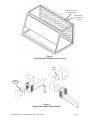
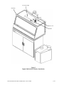
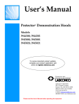
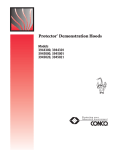
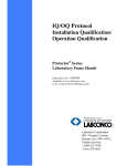
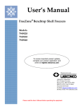
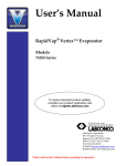
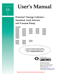
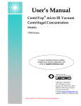
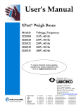
LABCONCO CORPORATION 8811 Prospect Ave, Kansas City, MO 64132
(816) 333-8811, Fax (816) 363-0130, (800) 821-5525
Guardian™ Digital Kit No 3908800, 02 or 3908801, 03
Guardian Digital 1000 Operation
The Guardian Digital Airflow Monitor consists of the airflow sensor, the Alarm Unit and the 15
VDC power supply. For 115V operation the alarm unit is powered by plugging the power
supply into the factory-prepared digital airflow monitor socket. For 230V operation, the Alarm
Unit is powered by plugging the power supply into a building outlet. The alarm has “Enter”,
“+”, and “-” buttons to program the monitor. There is also a green LED “SAFE”, yellow LED
“CAUTION”, and red LED “LOW” with audible alarm for airflow conditions. The audible
alarm can be permanently muted if desired. The Guardian Digital 1000 Airflow Monitor
displays a face velocity value, provides an RS232 communications port to a PC or building
computer system, can be configured for external input connections such as night setback or
external alarm and provides up to three output relays that can be configured. For complete
detailed information, please refer to the separate Labconco 1000 Alarm User’s Manual provided
with the enclosure.
Installation Procedure
1.
The enclosure comes prepared to except the Guardian™ Digital airflow monitor system.
2.
First remove the large 1.19" dia. gray hole plug. See Figure 1. See Figure 2 only to
reference internal assembly of the airflow monitor. Locate the elbow, locknut, and washer
and install it in the 1.19" dia. hole per Figure 1 and Figure 2. The enclosure baffle pivots
down to install the elbow, washer and locknut.
3.
Cut the 1" hose supplied with the kit to 10.5" approximate length and install it between the
airflow sensor and the elbow.
4.
Secure the Guardian Digital alarm to the enclosure with double stick tape as shown in
Figure 3. The airway passage between the alarm module and the enclosure is now
complete.
5.
Locate the metal hose cover and install with double stick tape per Figure 3. (Omit this step
on the Protector Work Stations.)
6.
Locate the power supply transformer. One end should already be connected to the twopin connector labeled 15 VDC on the back of the alarm module and through the strain
relief bushing. If disconnected, then reconnect to power the airflow monitor. Plug the
115V power supply into a standard 115V duplex receptacle, the back of the accessory
FilterMate portable exhauster or the back of the accessory light. For 230V, plug into a
standard receptacle with your specific outlet plug. (It is recommended that the airflow
monitor be connected directly to the FilterMate switched auxiliary outlet so the
airflow monitor is powered at the same time.)
7.
Installation is now complete.
Labconco Instruction Sheet 3909400, Rev. F, ECO F288
1 of 7
Remove Large 1.19"
Dia. Hole Plug
Install Elbow,
Locknut and
Washer
Figure 1
Hole Plug and Mounting Screws Location
Airflow
Sensor
Display
Digital 1000
Monitor
Figure 2
Digital 1000 Airflow Monitor Details
Labconco Instruction Sheet 3909400, Rev. F, ECO F288
2 of 7
Accessory Light
Enclosure
Hose Cover
Monitor
Figure 3
Digital 1000 Airflow Monitor Installation
Labconco Instruction Sheet 3909400, Rev. F, ECO F288
3 of 7
Digital 1000 Calibration
1. Calibrate the airflow monitor according to the instruction manual that comes with the kit.
To successfully calibrate, it will be necessary to change the face velocity by adjusting the
airflow exhaust volume. The exhaust volume can be adjusted with the speed control on
the FilterMate or by using an adjustable damper on the exhaust blower. Typical
calibration conditions are set at face velocity air sample differences of at least 20 feet per
minute. The airflow monitor is factory set to be calibrated with a difference of at least 50
fpm and can be changed by changing the “lower/higher air sample difference”. The
following suggested in flow face velocity speeds are recommended to successfully
calibrate. Typical low air alarms are set 10-20 fpm below operational speeds. Follow
Step 2 below and review the Labconco 1000 Alarm User’s Manual that comes with the
airflow monitor.
Low Air Alarm
Set Point
40 - 50 fpm
60 - 70 fpm
80 – 90 fpm
Enclosure Operating
In flow Speed
60 fpm
80 fpm
100 fpm
Low Calibration
Set Point
40 - 60 fpm
50 - 90 fpm
50 – 110 fpm
High Calibration
Set Point
100 – 120 fpm
100 – 150 fpm
100 – 170 fpm
2. Go to setup and then CAL CONFIG MENU and change the “lower/higher air sample
difference” to 20 fpm. This will allow you to successfully calibrate with values of a
minimum of 20 fpm difference.
3. While in CAL CONFIG MENU, change the “sensor difference” from 10% to 3%.
4. While in CAL CONFIG MENU, adjust the red low air alarm to the desired setting such
as 55 fpm. Then adjust the yellow “CAUTION or WARNING” to 59 fpm. Then adjust
the “CAUTION or WARNING” air reset to 3 fpm. This sets the alarm condition.
5. To complete the CAL CONFIGURATION, be sure to enter “DONE”.
6. To start the calibration mode, use the Labconco 1000 Manual and enter
“CALIBRATION” mode on the display from the SETUP menu.
7. Follow the instructions on the display and alter the low exhaust volume with the speed
control on the FilterMate or exhaust damper. Measure the average face velocity and
enter the low value on the display. Be careful not to block the opening. The low exhaust
volume calibration will take about 5 seconds.
8. Now alter the high exhaust volume with the speed control on the FilterMate or exhaust
damper. Measure the average face velocity and enter the high value on the display. The
high value must be at least 20 fpm greater than the low value. The high exhaust volume
calibration will take about 5 seconds.
9. Be sure to enter “DONE” after successfully completing the low and high calibration set
points.
10. Once calibration is completed, go to “RUN” and hit “ENTER”. The value should read
close to the high calibration set point.
11. To lower the face velocity to the operating point, simply alter the exhaust volume with
the speed control on the FilterMate or exhaust damper. Then recheck the face velocity
with an anemometer to confirm the display on the digital airflow monitor.
Labconco Instruction Sheet 3909400, Rev. F, ECO F288
4 of 7
Digital 1000 Alternate Calibration Procedure - Constant Volume Conditions
1.
To successfully calibrate, it will be necessary to change the face velocity by opening and
closing the enclosure’s sash. The airflow monitor is factory set to be calibrated with a
difference of at least 50 fpm and can be changed by adjusting the “lower/higher air
sample difference”. The in flow face velocity speeds provided in the chart below are
suggested to successfully calibrate the Digital 1000.
2.
Before proceeding with calibration, it will first be necessary to configure the airflow
monitor. Go to the setup and then CAL CONFIG MENU and adjust the “lower/higher air
sample difference” to 10 fpm. This will allow you to successfully calibrate with
minimum difference values of 10 fpm.
3.
While in CAL CONFIG MENU, change the “sensor difference” from 10% to 3%.
4.
While in CAL CONFIG MENU, adjust the red low alarm to the desired setting (See the
chart below for range and suggested settings). Then adjust the yellow “CAUTION or
WARNING” to the desired setting (See the chart below for range and suggested settings).
Then adjust the “CAUTION or WARNING” air reset to 3 fpm. This sets the alarm
condition.
CAUTION WARNING
“YELLOW LED” Setting
Range
user defined
(fpm)
Suggested
Set Point
(fpm)
43 – 53
63 – 73
83 - 93
51
67
83
LOW ALARM
“RED LED”
Setting
* Suggested
Range
user defined
Set Point
(fpm)
(fpm)
40 – 50
60 – 70
80 - 90
48
64
80
Low Calibration
Set Point
Sash Open
(fpm)
8” Sash
10” Sash
Height
Height
27
23
37
30
47
37
High Calibration
Set Point
or Enclosure
Operating
Inflow Speed
Sash Closed
60 fpm
80 fpm
100 fpm
* Because of airflow fluctuations in a typical laboratory environment Labconco suggests setting
the “RED LED” low alarm set point to 20% below the enclosure’s operating speed.
5.
To complete the CAL CONFIGURATION, be sure to enter “DONE”. If needed, refer to
the Configuration procedure provided on the following page for additional details.
6.
To start the calibration mode, enter “CALIBRATION” mode on the display from the
SETUP menu.
7.
Follow the instructions on the display and simulate the low exhaust volume by fully
opening the sash. You may measure the average face velocity for the low calibration set
point or utilize the calculated value provided in the chart above. The average face
velocity for the low set point is accurately measured by dividing the opening of the
enclosure into equal area grids consisting of at least 9 data collection points and
measuring the velocity at the center of each grid with a calibrated thermo anemometer.
Enter the low value on the display. Be careful not to block the opening. The low exhaust
volume calibration will take about 5 seconds.
8.
Now simulate the high exhaust volume by fully closing the sash to its normal operating
position. Measure the average face velocity for the high calibration set point to confirm
that the source of constant air volume is providing the desired face velocity for the
enclosure. The average face velocity for the high set point is accurately measured by
dividing the opening of the enclosure into equal area grids consisting of at least 3 data
collection points and measuring the velocity at the center of each grid with a calibrated
Labconco Instruction Sheet 3909400, Rev. F, ECO F288
5 of 7
thermo anemometer. Enter the high value set point on the display. The high value must
be at least 10 fpm greater than the low value. The high exhaust volume calibration will
take about 5 seconds.
9.
Be sure to enter “DONE” after successfully completing the low and high calibration set
points.
10. Once calibration is completed, go to “RUN” and hit “ENTER”. The value should read
close to the high calibration set point.
11. With the sash fully open, the Digital 1000 monitor should go into “RED LED” low air
alarm if successfully calibrated.
Digital 1000 Alternate Configuration Procedure (for Constant Volume Conditions)
Note: Enter Button stores information and +/- Buttons allow for scrolling.
1. Push the “ENTER” Button on the face of the alarm until the “SET UP” Menu is
displayed.
2. Scroll to “SET UP” and hit “ENTER”.
3. The PASSWORD MENU displays (The Password is 0000). Press the ENTER button
repeatedly until the CAL CONFIG MENU is displayed.
4. In the CAL CONFIG MENU set the following:
CALIBRATION - CONFIGURATION MENU
DISPLAY UNITS
LOW AIR ALARM
“RED LED”
LOW AIR CUTOFF
WARNING AIR ALARM
“YELLOW LED”
WARNING AIR RESET
HIGH AIR ALARM
LOWER AIR SAMPLE FLUCTUATIONS
HIGHER AIR FLUCTUATIONS
LOWER / HIGHER AIR SAMPLE DIFFERENCE
WARN TO ALARM AIR TIME
ALARM TO WARN AIR TIME
SHOW AIR FLOW
SHOW TIME LINE OFF = DISPLAYS BAR GRAPH
AUDIBLE ALARM
SENSOR DIFFERENCE
SETTINGS
FPM
* 48 FPM (60 fpm Operating inflow)
* 64 FPM (80 fpm Operating inflow)
* 80 FPM (100 fpm Operating inflow)
OFF
* 51 FPM (60 fpm Operating inflow)
* 67 FPM (80 fpm Operating inflow)
* 83 FPM (100 fpm Operating inflow)
3 FPM
OFF
OFF
3%
3%
10 SECONDS
3 SECONDS
ON
OFF
ENABLED
2%
* (Suggested Air Alarm Settings) Refer to the chart on the previous page for a range of air
velocity settings that may be used.
5. To complete the CAL CONFIG, be sure to enter “DONE”. You are returned to the
Main Menu.
Labconco Instruction Sheet 3909400, Rev. F, ECO F288
6 of 7
The information contained in this manual and the accompanying products are copyrighted and all rights reserved by
Labconco Corporation. Labconco Corporation reserves the right to make periodic design changes without
obligation to notify any person or entity of such change.
Warranty
Labconco provides a warranty on all parts and factory workmanship. The warranty includes areas of
defective material and workmanship, provided such defect results from normal and proper use of the
equipment.
The warranty for all Labconco products will expire one year from date of installation or two years from
date of shipment from Labconco, whichever is sooner, except the following;
•
Purifier® Logic® Biological Safety Cabinets and PuriCare® Lab Animal Research Stations carry
a three-year warranty from date of installation or four years from date of shipment from
Labconco, whichever is sooner.
•
SteamScrubber® & FlaskScrubber® Glassware Washers carry a two-year warranty from date of
installation or three years from date of shipment from Labconco, whichever is sooner.
•
Blood Drawing Chairs carry a ten year warranty.
•
Carts carry a lifetime warranty.
•
Glassware is not warranted from breakage when dropped or mishandled.
This limited warranty covers parts and labor, but not transportation and insurance charges. In the event of
a warranty claim, contact Labconco Corporation or the dealer who sold you the product. If the cause is
determined to be a manufacturing fault, the dealer or Labconco Corporation will repair or replace all
defective parts to restore the unit to operation. Under no circumstances shall Labconco Corporation be
liable for indirect, consequential, or special damages of any kind. This statement may be altered by a
specific published amendment. No individual has authorization to alter the provisions of this warranty
policy or its amendments. Lamps and filters are not covered by this warranty. Damage due to corrosion
or accidental breakage is not covered.
Returned or Damaged Goods
Do not return goods without the prior authorization from Labconco. Unauthorized returns will not be accepted. If
your shipment was damaged in transit, you must file a claim directly with the freight carrier. Labconco Corporation
and its dealers are not responsible for shipping damages.
The United States Interstate Commerce Commission rules require that claims be filed with the delivery carrier
within fifteen (15) days of delivery.
Limitation of Liability
The disposal and/or emission of substances used in connection with this equipment may be governed by various
federal, state, or local regulations. All users of this equipment are required to become familiar with any regulations
that apply in the user’s area concerning the dumping of waste materials in or upon water, land, or air and to comply
with such regulations. Labconco Corporation is held harmless with respect to user’s compliance with such
regulations.
Contacting Labconco Corporation
If you have questions that are not addressed in this manual, or if you need technical assistance, contact Labconco’s
Customer Service Department or Labconco’s Product Service Department at 1-800-821-5525 or 1-816-333-8811,
between the hours of 7:00 a.m. and 6:00 p.m., Central Standard Time.
Labconco Instruction Sheet 3909400, Rev. F, ECO F288
7 of 7