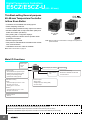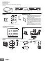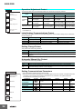
1
New Product
Digital Temperature Controllers
E5@Z
1/16, 1/8, and 1/4 DIN Temperature
Controllers Join the Best-selling
E5@Z Series
• Models available with either temperature inputs or
analog inputs.
• A wide range of functions, such as a loop break alarm
(LBA), manual output, and transfer output.
• Easy-to-read 11-segment display.
• Faster sampling at 250 ms.
• Setting Tool port provided as a standard feature for easy
connection to personal computers.
• New protocol called Modbus is installed in the models
with communications.
E5@Z Series
Digital Position-proportional
Controller
E5CZ
E5EZ
1/16 DIN
1/8 DIN
E5AZ
E5EZ-PRR
1/4 DIN
1/8 DIN
Contents
Digital Temperature Controllers
E5CZ/E5CZ-U .................................
2
E5AZ/E5EZ .....................................
14
E5EZ-PRR....................................................
37
Common to Updated E5@Z Controllers
• Operation......................................................
• Precautions ..................................................
E5EZ-PRR
26
33
• Operation......................................................
• Precautions ..................................................
43
59
1
Digital Temperature Controllers
E5CZ/E5CZ-U
(48 × 48 mm)
This Best-selling General-purpose
48×48-mm Temperature Controller
Is Now Even Better.
• Controllers now available with analog inputs.
• Faster sampling at 250 ms.
• Transfer output provided for easy output to recorders.
• Models available with a loop break alarm (LBA) and
heater short alarm (HS alarm).
• Easy setting with 11-segment displays.
• Setting protection indicator informs operator when
protection is enabled.
• Manual output provided.
• New protocol called Modbus is installed in the models
with communications.
• USB-Serial conversion cable is available.
48 × 48 mm
E5CZ
48 × 48 mm
E5CZ-U
Note: Refer to page 30 for information on changes in comparison to
previous models.
Note: Refer to Precautions on page 33.
Main I/O Functions
Event Inputs
• None
• Two
Sensor Inputs
• Universal thermocouple/Pt inputs
(Models with temperature inputs)
• Analog current/voltage inputs
(Models with analog inputs)
Indication Accuracy
E5CZ
• Thermocouple input: ±0.5% of PV
• Pt input: ±0.5% of PV
• Analog input: ±0.5% FS
E5CZ-U
• Thermocouple input: ±1% of PV
• Pt input: ±0.5% of PV
E5CZ
2-level Display: PV and SV
Alarm Outputs
• Two
4-digit Display
• Auto/manual switching
• Models also available with RS-485
communications
Control Output 1
• Relay output
• Voltage output (for driving SSR)
• Current output
Sampling Period
• 250 ms
This data sheet is provided as a guideline for selecting products. Be sure to refer to the following user manuals for application precautions
and other information required for operation before attempting to use the product.
E5CZ/E5CZ-U/E5AZ/E5EZ Digital Temperature Controllers User's Manual (Cat. No. H207)
E5CZ/E5CZ-U/E5AZ/E5EZ Digital Temperature Controllers Communications Manual (Cat. No. H208)
2
E5CZ/E5CZ-U
Model Number Structure
Model Number Legend
Controllers
Option Units
E5CZ-@2M@@
E53-CZ@@
1 2 3 4 5
1 2 3
1. Applicable Controller
CZ: E5CZ
2. Function 1
Blank: None
H:
Heater burnout/Heater short detection (CT1)
3. Function 2
B: Two event inputs
03: RS-485 communications
1. Control Output 1
R: Relay output
Q: Voltage output (for driving SSR)
C: Current output
2. Number of Alarms
2: Two alarms
3. Option
Blank: None
M:
Option Unit can be mounted.
4. Input Type
T: Thermocouple, infrared sensor/platinum resistance
thermometer
L: Analog current/voltage input
5. Power Supply Voltage
Blank: 100 to 240 VAC
D:
24 VAC/VDC
Note: Not all combinations of function 1 and function 2 specifications are possible for Option Units (E53-CZ@@).
Ordering Information
Controllers with Terminal Blocks
Size
Power supply
voltage
Input type
Alarm output
Mounting
option units
No
Thermocouple or
Resistance
thermometer
2
Yes
100 to 240 VAC
Analog
(current/voltage)
1/16 DIN
48 × 48 × 78
(W × H × D)
Thermocouple or
Resistance
thermometer
2
2
Yes
Yes
24 VAC/VDC
Analog
(current/voltage)
2
Yes
Control output
Previous
model
New model
Relay output
E5CZ-R2
E5CZ-R2T
Voltage output
(for driving SSR)
E5CZ-Q2
E5CZ-Q2T
Relay output
E5CZ-R2M
E5CZ-R2MT
Voltage output
(for driving SSR)
E5CZ-Q2M
E5CZ-Q2MT
Current output
E5CZ-C2M
E5CZ-C2MT
Relay output
None
E5CZ-R2ML
Voltage output
(for driving SSR)
None
E5CZ-Q2ML
Current output
None
E5CZ-C2ML
Relay output
E5CZ-R2MD
E5CZ-R2MTD
Voltage output
(for driving SSR)
E5CZ-Q2MD
E5CZ-Q2MTD
Current output
E5CZ-C2MD
E5CZ-C2MTD
Relay output
None
E5CZ-R2MLD
Voltage output
(for driving SSR)
None
E5CZ-Q2MLD
Current output
None
E5CZ-C2MLD
Option Units
One of the following Option Units can be mounted to provide the E5CZ with additional functions.
Functions
Previous model
Communications RS-485
Communications RS-485
Heater burnout
Event inputs
New model
E53-CN03N
E53-CZ03
E53-CNH03N
E53-CZH03
E53-CNBN
E53-CZB
Heater burnout
Event inputs
E53-CNHBN
Note: Option Units cannot be used for plug-in models.
These Option Units are applicable only to models released after October 2008.
E53-CZHB
3
E5CZ/E5CZ-U
Model Number Structure
Model Number Legend (Plug-in-type Controllers)
E5CZ-@2T@U
1 2 34 5
4. Power Supply Voltage
Blank: 100 to 240 VAC
D:
24 VAC/VDC
5. Plug-in type
U: Plug-in type
1. Output Type
R: Relay
Q: Voltage output (for driving SSR)
2. Number of Alarms
2: Two alarms
3. Input Type
T: Thermocouple, infrared sensor/platinum resistance
thermometer
Ordering Information (Plug-in-type Controllers)
Plug-in-Type Controllers
Size
Power supply
voltage
Input type
Alarm output
100 to 240 VAC
Thermocouple or
Resistance
thermometer
2
24 VAC/VDC
Thermocouple or
Resistance
thermometer
2
1/16 DIN
Control output
Relay output
Previous
model
New model
None
E5CZ-R2TU
Voltage output (for driving SSR) None
E5CZ-Q2TU
Relay output
None
E5CZ-R2TDU
Voltage output (for driving SSR) None
E5CZ-Q2TDU
Accessories (Order Separately)
Adapter
USB-Serial Conversion Cable
Model
Connectable models
E58-CIFQ1
Terminal Cover
Connectable models
Terminal block models
Model
E53-COV17
Sockets (for Plug-in Models)
Type
Waterproof Packing
Model
Y92S-29
Note: The Waterproof Packing is included with the Controller only for
models with terminal blocks.
Current Transformers (CTs)
4
Model
Terminal block models
Y92F-45
Note: Use this Adapter when the panel has been previously prepared
for the E5B@.
Hole diameter
Model
5.8 dia.
E54-CT1
12.0 dia.
E54-CT3
Model
Front-connecting Socket
P2CF-11
Front-connecting Socket with Finger Protection
P2CF-11-E
Back-connecting Socket
P3GA-11
Terminal Cover for Back-connecting socket with
Finger Protection
Y92A-48G
E5CZ/E5CZ-U
Specifications
Ratings
Power supply voltage
Operating voltage range
Power consumption
100 to 240 VAC, 50/60 Hz
24 VAC, 50/60 Hz or 24 VDC
85% to 110% of rated supply voltage
E5CZ
7.5 VA
5.5 VA (24 VAC)/3.5 W (24 VDC)
E5CZ-U
6 VA
4.5 VA (24 VAC)/2.5 W (24 VDC)
Models with temperature inputs
Thermocouple: K, J, T, E, L, U, N, R, S, or B
Platinum resistance thermometer: Pt100 or JPt100
Infrared temperature sensor: 10 to 70°C, 60 to 120°C, 115 to 165°C, or 140 to 260°C
Voltage input: 0 to 50 mV
Sensor input
Models with analog inputs
Current input: 4 to 20 mA or 0 to 20 mA
Voltage input: 1 to 5 V, 0 to 5 V, or 0 to 10 V
Input impedance
Current input: 150 Ω, Voltage input: 1 MΩ (Use a 1:1 connection when connecting the ES2-HB.)
E5CZ
SPST-NO, 250 VAC, 3 A (resistive load), electrical life: 100,000 operations, minimum applicable
load: 5 V, 10 mA
E5CZ-U
SPDT, 250 VAC, 3 A (resistive load), electrical life: 100,000 operations, minimum applicable load:
5 V, 10 mA
Voltage output
E5CZ
(for driving
E5CZ-U
SSR)
Output voltage: 12 VDC ±15% (PNP), max. load current: 21 mA, with short-circuit protection circuit
Current output E5CZ
4 to 20 mA DC/0 to 20 mA DC, load: 600 Ω max., resolution: approx. 2,700
Relay output
Control
output
SPST-NO, 250 VAC, 1 A (resistive load), electrical life: 100,000 operations, minimum applicable load: 5 V,
10 mA
Alarm output
Event input
Contact input
ON: 1 kΩ max., OFF: 100 kΩ min.
Non-contact
input
ON: Residual voltage: 1.5 V max., OFF: Leakage current: 0.1 mA max.
Outflow current: Approx. 7 mA per point
Control method
ON/OFF control or 2-PID control (with auto-tuning)
Setting method
Digital setting using front panel keys
Indication method
11-segment digital display and individual indicators (7-segments displays also possible)
Character height: PV: 11 mm, SV: 6.5 mm
Other functions
Manual output, heating/cooling control, transfer output (on some models), loop break alarm, multi SP, MV
limiter, input digital filter, self-tuning, temperature input shift, run/stop, protection functions, etc.
Ambient operating
temperature
−10 to 55°C (with no icing or condensation)
Ambient operating humidity
25% to 85%
Storage temperature
−25 to 65°C (with no icing or condensation)
5
E5CZ/E5CZ-U
Input Ranges
Thermocouples/Platinum Resistance Thermometers (Universal Inputs)
Input
Type
Platinum resistance
thermometer
Name
Pt100
Thermocouple
JPt100
K
J
T
E
L
Infrared temperature
sensor
U
N
R
S
B
10 to
70°C
60 to
120°C
115 to
165°C
140 to
260°C
Temperature range (°C)
Setting
number
1700
1300
1700
1300
850
850
850
600
500.0
500.0
500.0
400.0
400
400.0
400
400.0
260
100.0
100.0
120
165
0
0
0
0
19
20
21
22
90
100
0.0
−200
−199.9
0
1
0.0
−199.9
2
3
0
−20.0
−100
−20.0
6
7
8
−200
4
5
The applicable standards for the input types
are as follows:
0
0
16
17
−100
−200
−199.9
9
10
11
12
−200
−199.9
−200
13
14
15
U: Cu-CuNi, DIN 43710-1985
18
JPt100: JIS C 1604-1989, JIS C 1606-1989
L: Fe-CuNi, DIN 43710-1985
Models with Analog Inputs
Input Type
Current
Voltage
Input specification
4 to 20mA 0 to 20 mA 1 to 5 V
Setting range
Usable in the following ranges by scaling:
−1999 to 9999, −199.9 to 999.9, −19.99 to 99.99 or
−1.999 to 9.999
Setting number
0
1
2
0 to 5 V
3
0 to 10 V
4
23
Shaded settings are the default settings.
Pt100: IEC 751
K, J, T, E, N, R, S, B: IEC584-1
6
0 to 50 mV
Usable in
the
following
ranges by
scaling:
−1999 to
9999 or
−199.9 to
999.9
1800
1800
1700
1600
1500
1400
1300
1200
1100
1000
900
800
700
600
500
400
300
200
100
0
−100.0
−200.0
Analog
input
Shaded settings are the default settings.
E5CZ/E5CZ-U
Alarm Types
Select alarm types out of the 12 alarm types listed in the following
table.
Set
value
0
1
(See
note 1.)
2
3
Alarm output operation
Alarm type
Alarm function
OFF
Output OFF
Upper- and lowerlimit
ON
OFF
Upper limit
ON
OFF
Lower limit
ON
OFF
L
H
(See note 2.)
SP
H<0, L<0
L
H SP
H<0, L>0
|H| < |L|
H
SP L H
H>0, L<0
|H| > |L|
SP
L
H<0, L>0
|H| ≥ |L|
L SP
H
SP
X
ON
OFF
ON
OFF
SP
L
Case 3 (Always ON)
Case 2
H<0, L<0
X
L
SP
H SP
H<0, L>0
|H| < |L|
X
SP L
H
H
H>0, L<0
|H| > |L|
H
SP
L
L SP
SP
SP H L
L H
Upper- and lower- ON
OFF
limit with standby
SP
sequence
(See note 5.)
6
Upper-limit with
standby sequence
ON
OFF
8
Absolute-value
upper-limit
ON
OFF
9
Absolute-value
lower-limit
ON
OFF
10
Absolute-value
upper-limit with
standby sequence
ON
OFF
Absolute-value
lower-limit with
standby sequence
ON
OFF
H
(See note 3.)
SP
X
ON
OFF
Lower-limit with
standby sequence
LBA (for alarm 1
type only)
L
ON
OFF
SP
X
SP
X
0
X
0
X
0
X
0
(See note 4.)
ON
OFF
ON
OFF
ON
OFF
ON
OFF
ON
OFF
ON
OFF
H>0, L<0
|H| ≤ |L|
3. Set value: 4, Upper- and lower-limit range
Case 1
X
5
(See
note 1.)
12
(See
note 6.)
Case 3 (Always ON)
SP H
Upper- and lowerlimit range
11
Case 2
Case 1
When X is posi- When X is negative
tive
4
(See
note 1.)
7
Note: 1. With set values 1, 4 and 5, the upper and lower limit values
can be set independently for each alarm type, and are
expressed as “L” and “H.”
2. Set value: 1, Upper- and lower-limit alarm
X
SP
X
SP
X
0
H<0, L>0
|H| ≥ |L|
H>0, L<0
|H| ≤ |L|
4. Set value: 5, Upper- and lower-limit with standby sequence
For Upper- and Lower-Limit Alarm Described Above
• Case 1 and 2
Always OFF when the upper-limit and lower-limit
hysteresis overlaps.
• Case 3: Always OFF
5. Set value: 5, Upper- and lower-limit with standby sequence
Always OFF when the upper-limit and lower-limit hysteresis
overlaps.
6. Set value: 12, LBA (loop break alarm) can be set only for
alarm 1 type.
Set the alarm types for alarms 1 to 3 independently in the initial setting
level. The default setting is 2 (upper limit).
X
0
X
0
X
0
---
7
E5CZ/E5CZ-U
Characteristics
Indication accuracy
Thermocouple: (See note 1.)
E5CZ:
(±0.5% of indicated value or ±1°C, whichever
is greater) ±1 digit max.
E5CZ-U: (±1% of indicated value or ±2°C, whichever is
greater) ±1 digit max.
Platinum resistance thermometer:
(±0.5% of indicated value or ±1°C, whichever
is greater) ±1 digit max.
Analog input: ±0.5% FS ±1 digit max.
CT input: ±5% FS ±1 digit max.
Influence of temperature R, S, and B thermocouple inputs:
(See note 2.)
(±1% of PV or ±10°C, whichever is greater) ±1 digit max.
Other thermocouple inputs:
(±1% of PV or ±4°C, whichever is greater) ±1 digit max.
*±10°C for −100°C or less for K sensors
Influence of voltage
Platinum resistance thermometer inputs:
(See note 2.)
(±1% of PV or ±2°C, whichever is greater) ±1 digit max.
Analog inputs:
(±1% of FS) ±1 digit max.
USB-Serial Conversion Cable
Applicable OS
Windows 2000/XP/Vista
Applicable software
Thermo Mini
Applicable models
E5CZ/E5CZ-U/E5AZ/E5EZ
USB interface standard
Conforms to USB Specification 1.1.
DTE speed
38400 bps
Proportional band (P)
Models with thermocouple/platinum resistance
thermometer input (universal input):
0.1 to 999.9 EU (in units of 0.1 EU)
Models with analog input:
0.1 to 999.9% FS (in units of 0.1% FS)
Connector specifications
Computer: USB (type A plug)
Temperature Controller: Setup Tool port
(on bottom of Controller)
Integral time (I)
0 to 3999 s (in units of 1 s)
Power supply
Bus power (Supplied from USB host
controller.)
Derivative time (D)
0 to 3999 s (in units of 1 s)
Power supply voltage
5 VDC
Control period
0.5, 1 to 99 s (in units of 1 s)
Current consumption
70 mA
Manual reset value
0.0 to 100.0% (in units of 0.1%)
Alarm setting range
−1999 to 9999 (decimal point position depends on input
type)
Ambient operating humidity
10% to 80%
Sampling period
250 ms
Storage temperature
−20 to 60°C (with no condensation or
icing)
Affect of signal source
resistance
Thermocouple: 0.1°C/Ω max. (100 Ω max.) (See note 3.)
Platinum resistance thermometer: 0.4°C/Ω max. (10 Ω
max.)
Storage humidity
10% to 80%
Altitude
2,000 m max.
Weight
Approx. 100 g
Models with thermocouple/platinum resistance
thermometer input (universal input):
0.1 to 999.9 EU (in units of 0.1 EU)
Models with analog input:
0.01 to 99.99% FS (in units of 0.01% FS)
Hysteresis
Insulation resistance
Dielectric strength
20 MΩ min. (at 500 VDC)
2,000 VAC, 50 or 60 Hz for 1 min (between terminals with
different charge)
Ambient operating temperature 0 to 55°C (with no condensation or icing)
Note: A driver must be installed in the personal computer. Refer to
installation information in the operation manual for the
Conversion Cable.
Vibration
resistance
Malfunction
10 to 55 Hz, 20 m/s2 for 10 min each in X, Y, and Z
directions
Destruction
10 to 55 Hz, 0.75-mm single amplitude for 2 hrs each in
X, Y, and Z directions
Shock
resistance
Malfunction
100 m/s2 min., 3 times each in X, Y, and Z directions
Destruction
300 m/s2 min., 3 times each in X, Y, and Z directions
Transmission line
RS-485 multipoint
connection method
E5CZ
Controller: Approx. 150 g, Mounting Bracket: Approx.
10 g
Communications
RS-485 (two-wire, half duplex)
E5CZ-U
Controller: Approx. 110 g, Mounting Bracket: Approx.
10 g
Synchronization
method
Start-stop synchronization
E5CZ
Front panel: IP66 (indoor use)
Rear case: IP20, Terminals: IP00
Baud rate
1200, 2400, 4800, 9600, 19200, or 38400 bps
Weight
Degree of
protection
8
Note: 1. The indication accuracy of K thermocouples in the −200 to
1300°C range, T and N thermocouples at a temperature of
−100°C max., and U and L thermocouples at any
temperature is ±2°C ±1 digit maximum. The indication
accuracy of the B thermocouple at a temperature of 400°C
max. is not specified. The indication accuracy of the R and
S thermocouples at a temperature of 200°C max. is ±3°C ±1
digit max.
2. “EU” stands for Engineering Unit and is used as the unit
after scaling. For a temperature sensor, the EU is °C or °F.
3. B, R, and S sensors: 0.2°C/Ω max. (100 Ω max.)
4. There is no waterproof function for the E5CZ-U.
E5CZ-U
Front panel: Equivalent to IP50, Rear case: IP20,
Terminals: IP00 (See note 4.)
Memory protection
Non-volatile memory (number of writes: 1,000,000
times)
EMC
Emission Enclosure: EN55011 Group1 Class A
Emission AC Mains: EN55011 Group1 Class A
Immunity ESD: EN61000-4-2 4 kV contact discharge
(level 2)
8 kV air discharge (level 3)
Immunity RF-interference:
EN61000-4-3 10 V/m
(80-1000 MHz, 1.4-2.0 GHz amplitude
modulated) (level 3)
10 V/m (900 MHz pulse modulated)
Immunity Conducted Disturbance:
EN61000-4-6 3 V
(0.15 to 80 MHz) (level 2)
Immunity Burst: EN61000-4-4 2 kV Power-line (level 3)
1 kV I/O signal-line (level 3)
Immunity Surge: EN61000-4-5 1kV line to line
Power line, output line (relay output)
2 kV line to ground
Power line, output line (relay output)
1 kV line to ground
Input line (communication)
Immunity Voltage Dip/Interrupting:
EN61000-4-11 0.5 cycle, 100% (rated
voltage)
Approved standards
UL 61010C-1
CSA C22.2 No.1010.1
Conformed standards
EN61326, EN61010-1, IEC61010-1
VDE0106 Part 100 (Finger protection), when the
terminal cover is mounted.
Communications Specifications
Transmission code ASCII
Data length
7 or 8 bits
Stop bits
1 or 2 bits
Error detection
Vertical parity (none, even, odd)
Frame check sequence (FCS) with SYSWAY
Block check character (BCC) with CompoWay/F or
CRC-16 Modbus
Flow control
None
Interface
RS-485
Retry function
None
Communications
buffer
40 bytes
Send data wait time
0 to 99 ms
Default: 20 ms
Note: The baud rate, data length, stop bits, and vertical parity can be
individually set using the Communications Setting Level.
E5CZ/E5CZ-U
Current Transformer (Order Separately)
Ratings
Dielectric
strength
1,000 VAC for 1 min
Vibration
resistance
50 Hz, 98 m/s2
Weight
E54-CT1: Approx. 11.5 g, E54-CT3: Approx. 50 g
Maximum
50 A AC
heater current
Input current
indication
accuracy
±5% FS ±1 digit max.
Heater burnout alarm setting range
0.1 to 49.9 A (in units of 0.1 A)
0.0 A: Heater burnout/Heater short alarm output
turns OFF.
50.0 A: Heater burnout/Heater short alarm output
turns ON.
Minimum detection ON time: 190 ms (See note 1.)
0.1 to 49.9 A (in units of 0.1 A)
0.0 A: Heater burnout/Heater short alarm output
Heater short
turns ON.
alarm setting 50.0 A: Heater burnout/Heater short alarm output
range
turns OFF.
Minimum detection OFF time: 190 ms (See note
2.)
Note: 1. If the ON time of control output 1 is less than 190 ms, heater
burnout and the heater current will not be measured.
2. If the OFF time of control output 1 is less than 190 ms,
heater short alarm and the heater current will not be
measured.
Electrical Life Expectancy Curve for
Relays (Reference Values)
500
300
100
50
100 V 50 Hz
∞
1 kΩ
10
Distortion
factor 10%
1
3%
1%
100 mV
100 Ω
10
RL = 10 Ω
1
100 µV
10
1
10
100 mA
1
10
100 1,000 A
Thru-current (Io) A (r.m.s.)
E54-CT3
Thru-current (Io) vs. Output Voltage (Eo)
(Reference Values)
Maximum continuous heater current: 120 A (50/60 Hz)
(Maximum continuous heater current for an OMRON Temperature
Controller is 50 A.)
Number of windings: 400±2
Winding resistance: 8±0.8 Ω
Output voltage (Eo) V (r.m.s.)
Heater Burnout and Heater Short Alarms
Output voltage (Eo) V (r.m.s.)
Maximum continuous heater current: 50 A (50/60 Hz)
Number of windings: 400±2
Winding resistance: 18±2 Ω
Accessories
Armatures (2)
(E54-CT3 only) Plugs (2)
Life (× 104 operations)
E54-CT1
Thru-current (Io) vs. Output Voltage (Eo)
(Reference Values)
100 V 50 Hz
∞
1 kΩ
500 Ω
10
Distortion
factor 10%
3%
1%
1
100 mV
100 Ω
50 Ω
10
RL = 10 Ω
1
30
100 µV
10
5
10
1
E5CZ
250 VAC, 30 VDC
(resistive load)
cosφ = 1
3
10
100 mA
1
10
100 1,000 A
Thru-current (Io) A (r.m.s.)
1
0
1
2
3
4
5
6
Switching current (A)
9
E5CZ/E5CZ-U
External Connections
• A voltage output (control output 1) is not electrically insulated from the internal circuits. When using a grounding thermocouple, do not connect
any of the control output terminals to ground. If the control output terminals are connected to ground, errors will occur in the measured
temperature values as a result of leakage current.
E5CZ
Relay output
250 VAC, 3 A
(Resistive load)
Alarm output (Relay output)
+
1
11
6
2
12
7
3
13
8
4
14
9
5
15
10
Control output 1
Voltage output
12 VDC, 21 mA
+
Current output mA
4 to 20 mA DC
−
0 to 20 mA DC
Load 600 Ω max.
−
A
B
−
−
V
B
+
+
Alarm output (Relay
Alarm output 2 output), 250 VAC, 1 A
Alarm output 1, HB alarm/HS (Resistive load)
alarm/input error
Input power supply
100 to 240 VAC
24 VAC/DC (no polarity)
Analog input TC/Pt
universal input
Option Units
E53-CZH03
Communications/
CT
B
E53-CZHB
Event inputs/
CT
11
11
E53-CZB
Event inputs
11
B
RS-485
A
E53-CZ03
Communications
11
RS-485
12
Do not
use. 13
EV1
EV1
Do not
13
use.
Do not
14
use.
Do not
15
use.
14
CT1
15
12
A
13
EV2
14
CT1
12
15
EV2
12
13
Do not
14
use.
Do not
15
use.
E5CZ-U
Relay output
SPDT 250 VAC, 3 A
Control output 1
(Resistive load)
+
Voltage output
A
12 VDC, 21 mA
B
B
+
TC/Pt
universal input
6
5
7
Alarm output (Relay output),
250 VAC, 1 A (Resistive load)
8
4
Alarm output 1/
input error
Alarm output 2
9
3
2
10
1
11
Input power supply
100 to 240 VAC
24 VAC/DC (no polarity)
Note: For the Wiring Socket, purchase the P2CF-11 or PG3A-11 separately.
10
E5CZ/E5CZ-U
Nomenclature
E5CZ
E5CZ-U
The front panel is the same for the E5CZ and E5CZ-U.
Temperature unit
OMRON
No. 1 display
Operation indicators
No. 2 display
Up Key
Level Key
Down Key
Mode Key
Dimensions
E5CZ
Terminal Models
48 × 48
(84)
78
6
Panel Cutout
Individual Mounting
Group Mounting
44.8 × 44.8
1.5
+1.0
0
OMRON
45 +0.6
0
58
Waterproofing is not possible
when group mounting
Controllers.
60 min.
Waterproof Packing (Accessory) Mounting Adapter (Accessory)
48 × 48
45 +0.6
0
(97)
(91)
6
48
1.5
45 +0.6
0
OMRON
48.8 58
Waterproof Packing (Accessory) Mounting Adapter (Accessory)
Terminal Cover (E53-COV17)
(Order separately)
Note: The terminal block cannot be removed.
E5CZ-U
Plug-in Models
• Recommended panel thickness is
1 to 5 mm.
• Group mounting is not possible in
the vertical direction. (Maintain the
specified mounting space between
Controllers.)
• To mount the Controller so that it is
waterproof, insert the waterproof
packing onto the Controller.
• When two or more Controllers are
mounted, make sure that the
surrounding temperature does not
exceed the ambient operating
temperature given in the
specifications.
Panel Cutout
Individual Mounting
Group Mounting
+1.0
0
6
48 × 48
(90.7)
70.5
14.2
44.8 × 44.8
45 +0.6
0
60 min.
58
45 +0.6
0
Mounting Adapter (Accessory)
48
Note: There is no waterproof function for the E5CZ-U.
45 +0.6
0
• Recommended panel thickness is
1 to 5 mm.
• Group mounting is not possible in
the vertical direction. (Maintain the
specified mounting space between
Controllers.)
• When two or more Controllers are
mounted, make sure that the
surrounding temperature does not
exceed the ambient operating
temperature given in the
specifications.
11
E5CZ/E5CZ-U
Accessories
USB-Serial Conversion Cable (Order Separately)
E58-CIFQ1
(2,100)
LED indicator (SD)
250
USB connector (type A plug)
1,765
Terminal Cover (Order Separately)
Waterproof Packing
E53-COV17
Y92S-29 (for DIN 48 × 48)
48
Serial connector
LED indicator (RD)
Order the Waterproof Packing separately if it becomes lost or
damaged.
The Waterproof Packing can be used to achieve an IP66
(indoor use) degree of protection.
(Deterioration, shrinking, or hardening of the waterproof
packing may occur depending on the operating environment.
Therefore, periodic replacement is recommended to ensure
the level of waterproofing specified in IP66 (indoor use). The
time for periodic replacement depends on the operating environment. Be sure to confirm this point at your site. Consider
one year a rough standard. OMRON shall not be liable for
the level of water resistance if the customer does not perform
periodic replacement.)
The Waterproof Packing does not need to be attached if a
waterproof structure is not required.
48.8
22
9.1
Note: The E53-COV10 cannot be used.
Note: There is no waterproof function for the E5CZ-U.
Unit Labels (Order Separately)
11.8
Y92S-L1 Type
Current Transformers (Order Separately)
E54-CT1
4.8
21
15
2.8
5.8 dia.
7.5
25
3
10.5
40
Two, 3.5 dia.
10
30
E54-CT3
E54-CT3 Accessory
• Armature
2.36 dia.
30
12 dia.
Approx. 3 dia.
Lead
40 × 40
30
12
• Plug
18
Approx. 6 dia.
15
Armature
Plug
9
Two, M3 (depth: 4)
Connection Example
(22)
E5CZ/E5CZ-U
Adapter (Order Separately)
Note: 1. Use this Adapter when the panel has already been prepared for the E5B@.
2. Only black is available.
Y92F-45
Fixture (Accessory)
76
4.7
69.6 to 77.6
72 × 72
67 × 67 87
Mounted to E5CZ
Panel (1 to 8 mm)
72 × 72
48 × 48
2.2
4.7
77.3 (to back of E5CZ)
E5CZ-U Wiring Socket (Order Separately)
Front-connecting Socket
P2CF-11
Eleven, M3.5 × 7.5
3
Terminal Layout/Internal Connections
(Top View)
4.5
7.8
sems screws
8 7 6 5
Mounting Holes
4
Two, 4.5 dia. mounting holes
35.4
70 max.
Two,
4.5-dia.
holes
4
9
3
10 11 1 2
40±0.2
Note: Can also be mounted to a DIN track.
50 max.
31.2 max.
Note: A model with finger protection (P2CF-11-E) is also available.
Back-connecting Socket
P3GA-11
27 dia.
4
7
3
Terminal Layout/Internal Connections
(Bottom View)
5 6 7 8
4
45
25.6
3
9
2 1 11 10
45
4.5 16.3 6.2
6
8.7
Note: 1. Using any other sockets will adversely affect accuracy. Use only the specified sockets.
2. A Protective Cover for finger protection (Y92A-48G) is also available.
13
Digital Temperature Controllers
E5AZ/E5EZ
(96 × 96 mm and 48 × 96 mm)
These Best-selling Generalpurpose Temperature Controllers
Are Now Even Better.
• Controllers now available with analog inputs.
• Faster sampling at 250 ms.
• Transfer output provided for easy output to
recorders.
• Models available with a loop break alarm (LBA) and
heater short alarm (HS alarm).
• Manual output provided.
• Easy setting with 11-segment displays.
• New protocol called Modbus is installed in the
models with communications.
• USB-Serial conversion cable is available.
96 × 96 mm
E5AZ
48 × 96 mm
E5EZ
Note: Refer to Precautions on page 33.
Note: Refer to page 30 for information on changes in comparison to
previous models.
Main I/O Functions
E5AZ
E5EZ
Event Inputs
• None
• Two
Sensor Inputs
• Universal thermocouple/Pt inputs
(Models with temperature inputs)
• Analog current/voltage inputs
(Models with analog inputs)
Indication Accuracy
• Thermocouple input: ±0.5% of PV
• Pt input: ±0.5% of PV
• Analog input: ±0.5% FS
Sampling Period
• 250 ms
14
2-level Display: PV and SV
4-digit Display
Alarm Outputs
• Three
Control Output 1
• Relay output
• Voltage output (for driving SSR)
• Current output
• Auto/manual switching
• Models also available with
RS-485 or RS-232C
communications
E5AZ/E5EZ
Model Number Structure
Model Number Legend
Controllers
Option Units
E5AZ/EZ-@3@@@@
E53-AZ@
1 23 4 5 6
1. Control Output 1
R: Relay output
Q: Voltage output (for driving SSR)
C: Current output
2. Number of Alarms
3: Three alarms
3. Heater Burnout/Heater Short
Blank: None
H:
Heater burnout/Heater short detection (CT1)
4. Option
Blank: None
M: Option Unit can be mounted.
5. Input Type
T: Thermocouple, infrared sensor/platinum resistance
thermometer
L: Analog current/voltage input
6. Power Supply Voltage
Blank: 100 to 240 VAC
D:
24 VAC/VDC
1 2
1. Applicable Controller
AZ: E5AZ/E5EZ
2. Function
01: RS-232C communications
03: RS-485 communications
B: Two event inputs
Ordering Information
Controllers with Terminal Blocks
Functions
Size
Power supply
voltage
Input type
Alarm
output
Control output
3
100 to
240 VAC
Analog (current/
3
voltage)
Thermocouple
or Resistance
thermometer
3
24 VAC/VDC
Analog (current/
3
voltage)
Previous model
New model
No
E5AZ-R3
E5AZ-A3 + E53-AZR
E5AZ-R3T
Voltage output
No
(for driving SSR)
No
E5AZ-Q3
E5AZ-A3 + E53-AZQ
E5AZ-Q3T
Current output
No
No
E5AZ-C3
E5AZ-A3 + E53-AZC
E5AZ-C3T
Relay output
No
Yes
E5AZ-R3 + E53-AZM
E5AZ-R3MT
Voltage output
No
(for driving SSR)
Yes
E5AZ-Q3 + E53-AZM
E5AZ-Q3MT
Current output
Yes
E5AZ-C3 + E53-AZM
E5AZ-C3MT
No
Yes (CT1) Yes
E5AZ-R3 + E53-AZM +
E5AZ-R3HMT
E53-AZH
Voltage output
Yes (CT1) Yes
(for driving SSR)
E5AZ-Q3 + E53-AZM +
E5AZ-Q3HMT
E53-AZH
Relay output
Relay output
1/4 DIN
96 × 96 × 78
(W × H × D)
Mounting
option
units
No
Relay output
Thermocouple
or Resistance
thermometer
Heater
burnout
Yes (CT1) Yes
None
E5AZ-R3HML
Voltage output
Yes (CT1) Yes
(for driving SSR)
None
E5AZ-Q3HML
Current output
No
Yes
None
E5AZ-C3ML
Relay output
No
Yes
None
E5AZ-R3MTD
Voltage output
No
(for driving SSR)
Yes
None
E5AZ-Q3MTD
Current output
No
Yes
None
E5AZ-C3MTD
Relay output
Yes (CT1) Yes
None
E5AZ-R3HMTD
Voltage output
Yes (CT1) Yes
None
E5AZ-Q3HMTD
Relay output
Yes (CT1) Yes
None
E5AZ-R3HMLD
Voltage output
Yes (CT1) Yes
(for driving SSR)
None
E5AZ-Q3HMLD
Current output
None
E5AZ-C3MLD
---
Yes
15
E5AZ/E5EZ
Controllers with Terminal Blocks
Functions
Power supply
voltage
Size
Alarm
output
Input type
Control output
100 to
240 VAC
Analog (current/
voltage)
3
Thermocouple or
Resistance
3
thermometer
24 VAC/VDC
Analog (current/
voltage)
3
E5EZ-R3T
Voltage output
No
(for driving SSR)
No
E5EZ-Q3
E5EZ-A3 + E53-AZQ
E5EZ-Q3T
Current output
No
No
E5EZ-C3
E5EZ-A3 + E53-AZC
E5EZ-C3T
Relay output
No
Yes
E5EZ-R3 + E53-AZM
E5EZ-R3MT
Voltage output
No
(for driving SSR)
Yes
E5EZ-Q3 + E53-AZM
E5EZ-Q3MT
Current output
Yes
E5EZ-C3 + E53-AZM
E5EZ-C3MT
Communications Unit
Event Input Unit
Yes (CT1) Yes
Voltage output
Yes (CT1) Yes
(for driving SSR)
E5EZ-Q3 + E53-AZM +
E5EZ-Q3HMT
E53-AZH
Relay output
Yes (CT1) Yes
None
E5EZ-R3HML
Voltage output
Yes (CT1) Yes
(for driving SSR)
None
E5EZ-Q3HML
Current output
No
Yes
None
E5EZ-C3ML
Relay output
No
Yes
None
E5EZ-R3MTD
Voltage output
No
(for driving SSR)
Yes
None
E5EZ-Q3MTD
Current output
No
Yes
None
E5EZ-C3MTD
Relay output
Yes (CT1) Yes
None
E5EZ-R3HMTD
Voltage output
Yes (CT1) Yes
None
E5EZ-Q3HMTD
Relay output
Yes (CT1) Yes
None
E5EZ-R3HMLD
Voltage output
Yes (CT1) Yes
(for driving SSR)
None
E5EZ-Q3HMLD
Current output
None
E5EZ-C3MLD
E53-AZ03
Event input
E53-AZB
USB-Serial Conversion Cable
Model
E58-CIFQ1
Terminal Cover
Connectable models
E5AZ
E5EZ
Model
E53-COV11
Waterproof Packing
Connectable models
Model
E5AZ
Y92S-P4
E5EZ
Y92S-P5
Current Transformers (CTs)
16
Model
E53-AZ01
RS-485 Communications
Accessories (Order Separately)
Hole diameter
Model
5.8 dia.
E54-CT1
12.0 dia.
E54-CT3
No
E5EZ-R3 + E53-AZM +
E5EZ-R3HMT
E53-AZH
Function
RS-232C Communications
New model
E5EZ-R3
E5EZ-A3 + E53-AZR
Option Units
Name
Previous model
No
Relay output
1/8 DIN
48 × 96 × 78
(W × H × D)
Mounting
option
units
No
Relay output
Thermocouple or
Resistance
3
thermometer
Heater
burnout
-
Yes
E5AZ/E5EZ
Specifications
Ratings
Power supply voltage
100 to 240 VAC, 50/60 Hz
24 VAC, 50/60 Hz or 24 VDC
Operating voltage range
85% to 110% of rated supply voltage
Power consumption
8.5 VA
Sensor input
Models with temperature inputs
Thermocouple: K, J, T, E, L, U, N, R, S, or B
Platinum resistance thermometer: Pt100 or JPt100
Infrared temperature sensor: 10 to 70°C, 60 to 120°C, 115 to 165°C, or 140 to 260°C
Voltage input: 0 to 50 mV
6 VA (24 VAC)/4 W (24 VDC)
Models with analog inputs
Current input: 4 to 20 mA or 0 to 20 mA
Voltage input: 1 to 5 V, 0 to 5 V, or 0 to 10 V
Input impedance
Relay output
Control
output
Current input: 150 Ω, Voltage input: 1 MΩ (Use a 1:1 connection when connecting the ES2-HB.)
SPST-NO, 250 VAC, 5 A (resistive load), electrical life: 100,000 operations, minimum applicable load: 5 V,
10 mA
Voltage output
(for driving
Output voltage: 12 VDC +15%/−20% (PNP), max. load current: 40 mA, with short-circuit protection circuit
SSR)
Current output 4 to 20 mA DC/0 to 20 mA DC, load: 600 Ω max., resolution: approx. 2,700
SPST-NO, 250 VAC, 2 A (resistive load), electrical life: 100,000 operations, minimum applicable load: 5 V,
10 mA
Alarm output
Event input
Contact input
ON: 1 kΩ max., OFF: 100 kΩ min.
Non-contact
input
ON: Residual voltage: 1.5 V max., OFF: Leakage current: 0.1 mA max.
Outflow current: Approx. 7 mA per point
Control method
ON/OFF control or 2-PID control (with auto-tuning)
Setting method
Digital setting using front panel keys
Indication method
11-segment digital display and individual indicators (7-segments displays also possible)
Character height: E5AZ: PV: 15 mm, SV: 9.5 mm
E5EZ: PV: 14 mm, SV: 9.5 mm
Other functions
Manual output, heating/cooling control, transfer output (on some models), loop break alarm, multi SP, MV
limiter, input digital filter, self-tuning, temperature input shift, run/stop, protection functions, etc.
Ambient operating
temperature
−10 to 55°C (with no icing or condensation)
Ambient operating humidity
25% to 85%
Storage temperature
−25 to 65°C (with no icing or condensation)
17
E5AZ/E5EZ
Input Ranges
Thermocouples/Platinum Resistance Thermometers (Universal Inputs)
Input
Type
Platinum resistance
thermometer
Name
Pt100
Thermocouple
JPt100
K
J
T
E
L
Infrared temperature
sensor
U
N
R
S
B
10 to
70°C
60 to
120°C
115 to
165°C
140 to
260°C
Temperature range (°C)
Setting
number
1700
1300
1700
1300
850
850
850
600
500.0
500.0
500.0
400.0
400
400.0
400
400.0
260
100.0
100.0
120
165
0
0
0
0
19
20
21
22
90
100
0.0
−200
−199.9
0
1
0.0
0
−199.9
2
3
−20.0
−100
−20.0
6
7
8
−200
4
5
0
0
16
17
−100
−200
−199.9
9
10
11
12
−200
−199.9
−200
13
14
15
The applicable standards for the input types
are as follows:
U: Cu-CuNi, DIN 43710-1985
K, J, T, E, N, R, S, B: IEC 584-1
JPt100: JIS C 1604-1989, JIS C 1606-1989
18
Models with Analog Inputs
Input Type
Current
Voltage
Input specification
4 to 20mA 0 to 20 mA 1 to 5 V
Setting range
Usable in the following ranges by scaling:
−1999 to 9999, −199.9 to 999.9, −19.99 to 99.99 or
−1.999 to 9.999
Setting number
0
1
2
0 to 5 V
3
0 to 10 V
4
23
Shaded settings are the default settings.
Pt100: IEC 751
L: Fe-CuNi, DIN 43710-1985
18
0 to 50 mV
Usable in
the
following
ranges by
scaling:
−1999 to
9999 or
−199.9 to
999.9
1800
1800
1700
1600
1500
1400
1300
1200
1100
1000
900
800
700
600
500
400
300
200
100
0
−100.0
−200.0
Analog
input
Shaded settings are the default settings.
E5AZ/E5EZ
Alarm Types
Select alarm types out of the 12 alarm types listed in the following table.
Alarm output operation
Set value
0
1
(See note
1.)
2
3
Alarm type
Alarm function
OFF
When X is posi- When X is negative
tive
ON
OFF
Upper limit
ON
OFF
Lower limit
L
H
(See note 2.)
SP
X
SP
X
ON
OFF
Upper- and lowerlimit range
5
(See note
1.)
H
Upper- and lower- ON
OFF
limit with standby
SP
sequence
(See note 5.)
6
Upper-limit with
standby sequence
ON
OFF
7
Lower-limit with
standby sequence
ON
OFF
8
Absolute-value
upper-limit
ON
OFF
9
Absolute-value
lower-limit
ON
OFF
10
Absolute-value
upper-limit with
standby sequence
ON
OFF
Absolute-value
lower-limit with
standby sequence
ON
OFF
12
(See note
6.)
L
ON
OFF
ON
OFF
ON
OFF
SP
Case 1
X
LBA (for alarm 1
type only)
X
0
X
0
X
0
X
0
L
H<0, L>0
|H| ≥ |L|
L SP
H
L
Case 3 (Always ON)
Case 2
L
H SP
H<0, L>0
|H| < |L|
SP L
H
H
H>0, L<0
|H| > |L|
H
SP
L
L SP
SP H L
(See note 4.)
ON
OFF
ON
OFF
ON
OFF
ON
OFF
ON
OFF
ON
OFF
H>0, L<0
|H| ≤ |L|
H<0, L<0
SP
SP
SP
H>0, L<0
|H| > |L|
SP
3. Set value: 4, Upper- and lower-limit range
SP
L
X
H<0, L>0
|H| < |L|
H
SP L H
SP H
(See note 3.)
X
H SP
X
H
SP
Case 3 (Always ON)
H<0, L<0
L
Upper- and lowerlimit
Case 2
Case 1
Output OFF
4
(See note
1.)
11
Note: 1. With set values 1, 4 and 5, the upper and lower limit values
can be set independently for each alarm type, and are
expressed as “L” and “H.”
2. Set value: 1, Upper- and lower-limit alarm
X
SP
X
SP
X
0
X
0
H<0, L>0
|H| ≥ |L|
H>0, L<0
|H| ≤ |L|
4. Set value: 5, Upper- and lower-limit with standby sequence
For Upper- and Lower-Limit Alarm Described Above
• Case 1 and 2
Always OFF when the upper-limit and lower-limit
hysteresis overlaps.
• Case 3: Always OFF
5. Set value: 5, Upper- and lower-limit with standby sequence
Always OFF when the upper-limit and lower-limit hysteresis
overlaps.
6. Set value: 12, LBA (loop break alarm) can be set only for
alarm 1 type.
Set the alarm types for alarms 1 to 3 independently in the initial setting
level. The default setting is 2 (upper limit).
X
0
X
0
---
19
E5AZ/E5EZ
Characteristics
Indication accuracy
Influence of temperature (See note 2.)
Influence of voltage
(See note 2.)
Thermocouple: (See note 1.)
(±0.5% of indicated value or ±1°C, whichever is greater) ±1
digit max.
Platinum resistance thermometer:
(±0.5% of indicated value or ±1°C, whichever is greater) ±1
digit max.
Analog input: ±0.5% FS ±1 digit max.
CT input: ±5% FS ±1 digit max.
R, S, and B thermocouple inputs:
(±1% of PV or ±10°C, whichever is greater) ±1 digit max.
Other thermocouple inputs:
(±1% of PV or ±4°C, whichever is greater) ±1 digit max.
*±10°C for −100°C or less for K sensors
Platinum resistance thermometer inputs:
(±1% of PV or ±2°C, whichever is greater) ±1 digit max.
Analog inputs:
(±1% of FS) ±1 digit max.
USB-Serial Conversion Cable
Applicable OS
Windows 2000/XP/Vista
Applicable software
Thermo Mini
Applicable models
E5CZ/E5CZ-U/E5AZ/E5EZ
USB interface standard
Conforms to USB Specification 1.1.
DTE speed
38400 bps
Connector specifications
Computer: USB (type A plug)
Temperature Controller: Setup Tool port
(on bottom of Controller)
Hysteresis
Models with thermocouple/platinum resistance thermometer
input (universal input):
0.1 to 999.9 EU (in units of 0.1 EU) (See note 3.)
Models with analog input:
0.01 to 99.99% FS (in units of 0.01% FS)
Power supply
Bus power (Supplied from USB host
controller.)
Proportional band (P)
Models with thermocouple/platinum resistance thermometer
input (universal input):
0.1 to 999.9 EU (in units of 0.1 EU) (See note 3.)
Models with analog input:
0.1 to 999.9% FS (in units of 0.1% FS)
Power supply voltage
5 VDC
Current consumption
70 mA
Integral time (I)
0 to 3999 s (in units of 1 s)
Ambient operating temperature 0 to 55°C (with no condensation or icing)
Derivative time (D)
0 to 3999 s (in units of 1 s)
Ambient operating humidity
10% to 80%
Control period
0.5, 1 to 99 s (in units of 1 s)
Manual reset value
0.0 to 100.0% (in units of 0.1%)
Storage temperature
−20 to 60°C (with no condensation or
icing)
Alarm setting range
−1999 to 9999 (decimal point position depends on input type)
Storage humidity
10% to 80%
Sampling period
250 ms
Altitude
2,000 m max.
Affect of signal source
resistance
Thermocouple: 0.1°C/Ω max. (100 Ω max.) (See note 4.)
Platinum resistance thermometer: 0.4°C/Ω max. (10 Ω max.)
Weight
Approx. 100 g
Insulation resistance
20 MΩ min. (at 500 VDC)
Dielectric strength
2,000 VAC, 50 or 60 Hz for 1 min (between terminals with
different charge)
Note: A driver must be installed in the personal computer. Refer to
installation information in the operation manual for the
Conversion Cable.
Vibration
resistance
Malfunction
10 to 55 Hz, 20 m/s2 for 10 min each in X, Y, and Z directions
Destruction
10 to 55 Hz, 0.75-mm single amplitude for 2 hrs each in X, Y,
and Z directions
Shock
resistance
Malfunction
100 m/s2 min., 3 times each in X, Y, and Z directions
Transmission line con- RS-485 multipoint
nection method
RS-232C
Destruction
300 m/s2 min., 3 times each in X, Y, and Z directions
Communications
RS-485 (two-wire, half duplex), RS-232C
E5AZ
Controller: Approx. 300 g, Mounting Bracket: Approx. 100 g
Start-stop synchronization
E5EZ
Synchronization
method
Controller: Approx. 250 g, Mounting Bracket: Approx. 100 g
Baud rate
1200, 2400, 4800, 9600, 19200, or 38400 bps
Transmission code
ASCII
Weight
Communications Specifications
Degree of protection
Front panel: IP66 (indoor use),
Rear case: IP20, Terminals: IP00
Memory protection
Non-volatile memory (number of writes: 1,000,000 times)
Data length (See note.) 7 or 8 bits
Stop bits (See note.)
1 or 2 bits
Error detection
Vertical parity (none, even, odd)
Frame check sequence (FCS) with SYSWAY
Block check character (BCC) with CompoWay/F or
CRC-16 Modbus
Flow control
None
Interface
RS-485, RS-232C
EMC
Emission Enclosure: EN55011 Group1 Class A
Emission AC Mains: EN55011 Group1 Class A
Immunity ESD: EN61000-4-2 4 kV contact discharge (level
2)
8 kV air discharge (level 3)
Immunity RF-interference:
EN61000-4-3 10 V/m
(80-1000 MHz, 1.4-2.0 GHz amplitude
modulated) (level 3)
10 V/m (900 MHz pulse modulated)
Immunity Conducted Disturbance:
EN61000-4-6 3 V
(0.15 to 80 MHz) (level 2)
Immunity Burst: EN61000-4-4 2 kV Power-line (level 3)
1 kV I/O signal-line (level 3) (See note 5.)
Immunity Surge: EN61000-4-5 1kV line to line
Power line, output line (relay output)
2 kV line to ground
Power line, output line (relay output)
1 kV line to ground
Input line (communication)
Immunity Voltage Dip/Interrupting:
EN61000-4-11 0.5 cycle, 100% (rated
voltage)
Retry function
None
Communications
buffer
40 bytes
Send data wait time
0 to 99 ms
Default: 20 ms
Note: The baud rate, data length, stop bits, and vertical parity can be
individually set using the Communications Setting Level.
Approved standards
UL 61010C-1
CSA C22.2 No.1010.1
Current Transformer (Order Separately)
Conformed standards
EN61326, EN61010-1, IEC61010-1
VDE0106 Part 100 (Finger protection), when the terminal
cover is mounted.
Ratings
Note: 1. The indication accuracy of K thermocouples in the −200 to
1300°C range, T and N thermocouples at a temperature of
−100°C max., and U and L thermocouples at any
temperature is ±2°C ±1 digit maximum. The indication
accuracy of the B thermocouple at a temperature of 400°C
max. is not specified. The indication accuracy of the R and
S thermocouples at a temperature of 200°C max. is ±3°C ±1
digit max.
2. Conditions: Ambient temperature: −10°C to 23°C to 55°C,
Voltage range: −15% to +10% of rated voltage
3. “EU” stands for Engineering Unit and is used as the unit
after scaling. For a temperature sensor, the EU is °C or °F.
4. B, R, and S sensors: 0.2°C/Ω max. (100 Ω max.)
20
5. When using the E53-AZB, E53-AZ01, or E53-AZ03 Option
Unit with the E5AZ-@3@M@@ to satisfy the immunity burst
requirements in the EN 61326 standard, always connect a
ZCAT2035-0930 Clamp Filter (manufactured by TDK) to the
cable for terminals 11, 12, and 13.
Dielectric strength 1,000 VAC for 1 min
Vibration
resistance
50 Hz, 98 m/s2
Weight
E54-CT1: Approx. 11.5 g, E54-CT3: Approx.
50 g
Accessories
(E54-CT3 only)
Armatures (2)
Plugs (2)
E5AZ/E5EZ
Heater Burnout and Heater Short Alarms
Input current
indication
accuracy
±5% FS ±1 digit max.
Maximum continuous heater current: 50 A (50/60 Hz)
Number of windings: 400±2
Winding resistance: 18±2 Ω
Heater burnout alarm
setting range
0.1 to 49.9 A (in units of 0.1 A)
0.0 A: Heater burnout/Heater short alarm output
turns OFF.
50.0 A: Heater burnout/Heater short alarm output
turns ON.
Minimum detection ON time: 190 ms (See note 1.)
0.1 to 49.9 A (in units of 0.1 A)
0.0 A: Heater burnout/Heater short alarm output
Heater short
turns ON.
alarm setting 50.0 A: Heater burnout/Heater short alarm output
range
turns OFF.
Minimum detection OFF time: 190 ms (See note
2.)
Note: 1. If the ON time of control output 1 is less than 190 ms, heater
burnout detection and the heater current will not be
measured.
2. If the OFF time of control output 1 is less than 190 ms,
heater short alarm and the heater current will not be
measured.
Output voltage (Eo) V (r.m.s.)
Maximum
50 A AC
heater current
E54-CT1
Thru-current (Io) vs. Output Voltage (Eo)
(Reference Values)
100 V
50 Hz
∞
10
1 kΩ
Distortion
factor 10%
1
3%
1%
100 mV
100 Ω
10
RL = 10 Ω
1
100 µV
10
1
10
100 mA
1
10
1001,000 A
Thru-current (Io) A (r.m.s.)
500
Maximum continuous heater current: 120 A (50/60 Hz)
(Maximum continuous heater current for an OMRON Temperature
Controller is 50 A.)
Number of windings: 400±2
Winding resistance: 8±0.8 Ω
300
E5EZ
250 VAC, 30 VDC
(resistive load)
cosφ = 1
100
50
30
10
5
3
1
0
1
2
3
4
E54-CT3
Thru-current (Io) vs. Output Voltage (Eo)
(Reference Values)
5
6
Switching current (A)
Output voltage (Eo) V (r.m.s.)
Life (× 104 operations)
Electrical Life Expectancy Curve for
Relays (Reference Values)
100 V
50 Hz
∞
10
Distortion
factor 10%
3%
1%
1 kΩ
500 Ω
1
100 mV
100 Ω
50 Ω
10
RL = 10 Ω
1
100 µV
10
1
10
100 mA
1
10
1001,000 A
Thru-current (Io) A (r.m.s.)
21
E5AZ/E5EZ
External Connections
• The voltage output for control output 1 is not electrically insulated from the internal circuits. When using a grounding thermocouple, do not
connect any of the control output terminals to ground. If the control output terminals are connected to ground, errors will occur in the measured
temperature values as a result of leakage current.
E5AZ/E5EZ
E53-AZB
Event input
Option Units
100 to 240 VAC
24 VAC/DC (no polarity) Input power supply
Voltage output
12 VDC, 40 mA
Current output
4 to 20 mA DC
0 to 20 mA DC
Load 600 Ω max.
EV1
+
EV2
E53-AZ03
RS-485
SD
B(+)
RD
A(−)
SG
Do not use
EV2
EV1
Relay output 250 VAC,
5 A (Resistive load)
+
E53-AZ01
RS-232C
+
Control output 1
−
One CT
CT1
Alarm output 3
Do not use
Alarm output
(Relay output),
250 VAC, 2 A
(Resistive load)
Do not use
Alarm output 2
Alarm output 1,
HB alarm/HS
alarm/ input
error
A
TC −
B
B
+
+
Pt
−
mA
V
−
+
TC/Pt universal input
Analog input
Nomenclature
E5AZ
E5EZ
Temperature unit
Operation indicators
OMRON
OMRON
No. 1 display
Operation indicators
No. 1 display
Temperature unit
No. 2 display
Operation indicators
No. 2 display
Level Key
Up Key
Mode Key
Mode Key
Down Key
Level Key
22
Down Key
Up Key
E5AZ/E5EZ
Dimensions
E5AZ
11.2
96
91
78
2
96
91
112
Waterproof Packing
(Accessory)
Mounting Bracket
(Accessory)
11.2
96
91
84.5
2
96
112
Waterproof Packing
(Accessory)
92.5
Mounting Bracket
(Accessory)
Terminal Cover (E53-COV11)
(Order separately)
Crimp terminal size: M3.5
Panel Cutout
Group Mounting
Individual Mounting
+1.0
0
92+0.8
0
92+0.8
0
Note: To remove the Controller from the case, loosen the screw at
the bottom of the front panel with a screwdriver while
pressing down on the hook at the top of the front panel.
Waterproofing is not possible when
group mounting Controllers.
120 min.
92+0.8
0
• Recommended panel thickness is 1 to
8 mm.
• Group mounting is not possible in the
vertical direction. (Maintain the
specified mounting space between
Controllers.)
• To mount the Controller so that it is
waterproof, insert the waterproof
packing onto the Controller.
• When two or more Controllers are
mounted, make sure that the
surrounding temperature does not
exceed the ambient operating
temperature given in the
specifications.
23
E5AZ/E5EZ
E5EZ
Terminal Models
11.2
44
78
48
2
96
91
112
Waterproof Packing
(Accessory)
Mounting Bracket
(Accessory)
11.2
48
84.5
44
2
96
112
Waterproof Packing
(Accessory)
92.5
Mounting Bracket
(Accessory)
Terminal Cover (E53-COV11)
(Order separately)
Crimp terminal size: M3.5
Panel Cutout
Group Mounting
Individual Mounting
+1.0
0
45+0.6
0
92+0.8
0
Note: To remove the Controller from the case, loosen the screw
at the bottom of the front panel with a screwdriver while
pressing down on the hook at the top of the front panel.
Waterproofing is not possible when
group mounting Controllers.
120 min.
92+0.8
0
24
• Recommended panel thickness is 1 to
8 mm.
• Group mounting is not possible in the
vertical direction. (Maintain the
specified mounting space between
Controllers.)
• To mount the Controller so that it is
waterproof, insert the waterproof
packing onto the Controller.
• When two or more Controllers are
mounted, make sure that the
surrounding temperature does not
exceed the ambient operating
temperature given in the
specifications.
E5AZ/E5EZ
Accessories
USB-Serial Conversion Cable (Order Separately)
E58-CIFQ1
(2,100)
LED indicator (SD)
250
USB connector (type A plug)
Terminal Covers
Serial connector
LED indicator (RD)
Waterproof Packing
13
E53-COV11
(Two Covers provided.)
(Order Separately)
1,765
Y92S-P5 (for DIN 48 × 96)
Y92S-P4 (for DIN 96 × 96)
6.5 dia.
92.3
6.5
10.5
Order the Waterproof Packing separately if it becomes lost or damaged.
The Waterproof Packing can be used to achieve an IP66 (indoor use) degree
of protection.
(Deterioration, shrinking, or hardening of the waterproof packing may occur
depending on the operating environment. Therefore, periodic replacement is
recommended to ensure the level of waterproofing specified in IP66 (indoor
use). The time for periodic replacement depends on the operating environment. Be sure to confirm this point at your site. Consider one year a rough
standard. OMRON shall not be liable for the level of water resistance if the
customer does not perform periodic replacement.)
The Waterproof Packing does not need to be attached if a waterproof structure
is not required.
8
Unit Labels (Order Separately)
11.8
Y92S-L1 Type
4.8
Current Transformers (Order Separately)
E54-CT1
21
15
2.8
5.8 dia.
7.5
25
3
10.5
40
Two, 3.5 dia.
10
30
E54-CT3
E54-CT3 Accessory
2.36 dia.
30
Connection Example
• Armature
12 dia.
Armature
Plug
9
Approx. 3 dia.
Lead
40 × 40
18
Two, M3 (depth: 4)
• Plug
Approx. 6 dia.
15
30
(22)
25
E5@Z
Operation
Setting Levels Diagram
This diagram shows all of the setting levels. To move to the advanced function setting level, you must enter passwords. Some parameters are not
displayed depending on the protect level setting and the conditions of use.
Control stops when you move from the operation level to the initial setting level.
Power ON
Started in manual mode.
Started in automatic mode.
Press the O Key
for at least 1 s.
C
(See
note
2.)
Manual
mode
Press the
O Key less than 1 s.
a-m
Press the O Key for
at least 1 s; display
will flash.
Press the Ol Key for
at least 3 s while a-m
Manual Control
Level
Press the
O Key
for at
least 1 s.
Press the O +
M keys; display
will flash.
Adjustment Level
Operation Level
C
(See
note 1.)
Initial Setting Level
Press the O
+ M Keys for
at least 1 s.
Press the O Key for at
least 1 s; display will flash.
Press the O Key for at
100
least 3 s.
C
25
100
25
Press the O +
M Keys for at
least 3 s. (See
note.)
Control stops.
Communications
Press the Setting
Protect level
O Key for less than 1 s.
Press the O Key
for at least 1 s.
Input password.
Set value −169
Advanced Function
Setting Level
Note: The time taken to move
to the protect level can
be adjusted by
changing the "Move to
protect level time"
Control in progress
Control stopped
Not displayed for some models
Level change
Note: 1. Moves to operation level by software reset.
2. From the manual control level, key operations can be used to move to the operation level only.
Error Displays (Troubleshooting)
When an error occurs, the No.1 display shows the error code. Take necessary measure according to the error code, referring the table below.
Output status at error
No. 1 display
s.err (S. Err)
Meaning
Action
Control
outputs
Alarm outputs
Input error
(See note 2.)
Check the wiring of inputs for miswiring, disconnections, and short-circuits and check the
input type.
OFF
Operates as
above the upper
limit.
A/D converter
error
(See note 2.)
Check for an input error and then cycle the power supply. If the same error is still
displayed, repairs will be necessary.
If the Temperature Controller is normal after cycling the power supply, the error may have
been caused by noise. Check for noise being generated nearby.
OFF
OFF
OFF
OFF
OFF
OFF
e111 (E111)
Memory error
h.err (H. Err)
HB error
(See note 2.)
Cycle the power supply. If the same error is still displayed, repairs will be necessary.
If the Temperature Controller is normal after cycling the power supply, the error may have
been caused by noise. Check for noise being generated nearby.
Note: 1. If the input value exceeds the display limit (−1999 to 9999), though it is within the control range,
will be displayed under −1999 and
above 9999. Under these conditions, control output and alarm output will operate normally.
For details on the control range, refer to the E5CZ/E5CZ-U/E5AZ/E5EZ Digital Temperature Controllers User's Manual (Cat. No. H207).
2. These errors are displayed only when the PV/SP is displayed. Errors are not displayed in other display modes.
26
E5@Z
27
E5@Z
Parameters
Some parameters are not displayed depending on the
model of the Controller and parameter settings. For details,
refer to the E5CZ/E5CZ-U/E5AZ/E5EZ Digital
Temperature Controllers User's Manual (Cat. No. H207).
Press the O Key for at
least 3 s. Displays other than
that for switching between
automatic and manual.
Power ON
Starting in manual mode.
Starting in automatic
mode.
Manual control level
C
25 PID control
only
PV/MV
Press the
O Key for
at least 1 s
Press the O Key less than 1 s.
Operation Level
Adjustment Level
C
C
p
M
8.0
M
P
at AT execute/cancel
P
P
current 1 value
ct1 Heater
monitor
P
lcr1
0.0
M
P
Leakage current 1
monitor
hb1 Heater burnout detection 1
C
P
hs1 HS alarm 1
sp-0 SP 0
sp-1 SP1
C
0
M
C
SP used by
multi-SP
P
sp-3 SP 3
P
ins
0.0
M
C
point during SP
sp-m Set
ramp
C
0
M
P
ct1
0.0
M
P
current 1
lcr1 Leakage
monitor
0.0
P
value
al2h Alarm
upper limit 2
0
M
C
value
al2l Alarm
lower limit 2
0
M
C
al-3 Alarm value 3
0
M
C
r-s RUN/STOP
value
al3h Alarm
upper limit 3
0
M
run
M
C
value
al3l Alarm
lower limit 3
0
M
sprt SP ramp set value
P
o MV monitor
0.0 (heating)
M
ol-h MV upper limit
P
monitor
c-o MV
(cooling)
0.0
M
ol-l MV lower limit
-5.0
Temperature input shift
M
1-point shift
Upper-limit temperature
2-point shift
Set either of these parameters.
Press the O and M Keys for at
least 3 s. Display flashes.
Press the O and M Keys
for at least 1 s.
Press the OKey
less than 1 s
Protect Level
Communications Setting Level
The time taken to move to the protect level can be
adjusted by changing the "Move to protect level
time" setting.
Displayed only for models with communications.
Changes are effective after cycling power or
after a software reset.
temperature
insl Lower-limit
input shift value
0.0
M
Heater current 1 value
monitor
M
Hysteresis
settings
Hysteresis (cooling)
al-2 Alarm value 2
0
M
105.0
M
insh input shift value
0.0
M
C
m-sp Multi-SP
off
M
sp-2 SP 2
0
M
C
C
value
al1l Alarm
lower limit 1
0
M
C
1.0
M
0
M
C
Dead band
Heating/cooling
value
al1h Alarm
upper limit 1
0
M
C
0 set point setting
M
hys Hysteresis (heating)
chys
a-m
Cooling coefficient
Manual reset value
of-r Clear the offset during sta50.0 bilization of P or PD control.
1.0
M
C
0
M
C
c-db
P
M
C
50.0
M
C
c-sc
Press the
OKey for
at least 3 s.
0.0
M
0.0
M
P
Derivative time
1.00
M
0.0
M
P
d
P
al-1 Alarm value 1
0
M
C
0 set point
M
Auto/manual switch
PID control only.
Added when auto/manual
select addition is ON.
M
PID settings
C
PV display is ON.
25 Process value/
Integral time
40
M
off
M
P
C
233
M
off
M
cmwt Communications writing
i
value
25 Process
Added when Additional
Proportional band
Set either of these parameters. Set either of these parameters. Set either of these parameters.
Press the O Key less than 1 s.
P
Operation/adjustment protect
Restricts displaying and
menus in operation,
oapt modifying
adjustment, and manual
0
M
P
control levels.
Initial setting/communications
icpt protect
This protect level restricts
1 movement to the initial setting,
M
P
communications setting, and
advanced function setting levels.
wtpt Setting change protect
off Protects changes to setups by
operating the front panel keys.
M
setting
psel Protocol
Switches between CompoWay/F
cwf (SYSWAY) and Modbus.
M
u-no Communications Unit No.
1
M
baud rate
bps Communications
CompoWay/F
9.6
(SYSWAY) only
M
len Communications
data length
7
M
sbit Communications stop bits
2
M
prty Communications parity
even
M
sdwt Send data wait time
20
M
28
E5@Z
Press the O Key for at least 1 s.
Initial Setting Level
Advanced Function Setting Level
Press the O Key less than 1 s.
P
in-t
Input type
5
M
P
in-h
P
P
in-l
P
Scaling lower limit
0
M
P
dp
P
Decimal point
0
M
P
C
For input type of analog
Temperature unit
°C, °F
For input type of
c
temperature
M
SP upper limit
Limit the set point
1300
sl-l
cntl
PID ON/OFF
P
P
For input type of temperature, standard
control, or PID
M
cp Control period (heating)
20
M
P
C
P
Set the pulse output cycle.
c-cp Control period (cooling)
C
oreV Direct/reverse operation
P
alt1 Alarm 1 type
alt2 Alarm 2 type
P
alt3
P
2
M
P
tr-t Transfer output type
off
M
P
tr-h
Transfer output upper limit
tr-l
Transfer output lower limit
o1-t Linear current output
Linear output
Move to advanced function
amov setting level
when initial setting/
0 Displayed
communications protection is
M set to 0.
P
a1lt Alarm 1 latch
a2lt Alarm 2 latch
Standby sequence
rest reset
al1n Alarm 1 open in alarm
P
P
P
P
al2n Alarm 2 open in alarm
P
alh2 Alarm 2 hysteresis
P
al3n Alarm 3 open in alarm
P
alh3 Alarm 3 hysteresis
P
C
junction compencjc Cold
sation method
HS alarm hysteresis
lba
LBA detection time
lbal
LBA level
lbab
LBA band
out1
Control output 1
assignment
8.0
M
C
3.0
M
P
o
M
P
alm1
command logic
rlrv MB
switching
P
alm2
a1on Alarm 1 ON delay
P
alm3
a2on Alarm 2 ON delay
P
csel
on
M
off
M
0
M
0
M
Alarm output 1
alm1 assignment
M
Alarm output 2
alm2 assignment
M
Alarm output 3
assignment
alm3 (E5AZ/E5EZ only)
M
Character select
on
M
a3on Alarm 3 ON delay
0
M
hbu HB ON/OFF
P
hbl Heater burnout latch
P
burnout
hbh Heater
hysteresis
P
alfa α
sero Input error output
hsh
0
M
off
M
P
15.0
M
to protect level
prlt Move
time
HS alarm latch
0.1
M
3
M
alh1 Alarm 1 hysteresis
st-b ST stable range
a3lt Alarm 3 latch
hsl
off
M
off
M
a1of Alarm 1 OFF delay
0
M
a2of Alarm 2 OFF delay
0
M
a3of Alarm 3 OFF delay
0
M
0.1
M
P
4-20
M
P
P
C
0.0
M
P
P
off
M
Linear output
100.0
M
P
spru SP ramp time unit
on
M
Alarm 3 type
display
ret Automatic
return time
hsu HS alarm use
on
M
off
M
0.2
M
2
M
P
P
n-o
M
C
P
off
M
0.2
M
2
M
P
P
n-o
M
or-r
M
P
mspu
o-dp MV display
off
M
off
M
0.2
M
20
M
P
ev-2
P
n-o
M
When assigning PID
control output to
on (self-tuning) or
pulse output
P
ev-1
amad addition
off
M
a
M
s-hc Standard or heating/cooling
st ST
P
1 Four SPs: 2
M
Event input
assignment 1
none
M
Event input
assignment 2
stop
M
Multi-SP uses
m
M
P
stnd
M
of multi-SP uses
ev-m Number
Two SPs: 1
Auto/manual select
pvad Additional PV display
off
M
off
M
P
SP lower limit
onof
M
P
P
sl-h
-200
M
P
P
d-u
M
C
P
off
M
Scaling upper limit
100
M
init Parameter initialization
P
istp Input shift type
ins1
M
0.65
M
P
inf Input digital filter
0.0
M
Move by setting password (−169).
29
E5@Z
Improved Functions
Changes
Model numbers have been changed to allow for universal input
specifications.
Before Change
Precautions in Replacing Previous Controllers
• Previous E5@Z Controllers cannot be removed from the case for
replacement with new models. Replace the case at the same time.
E5@Z-@@@ (models for thermocouples and platinum resistance
thermometers)
None (models for analog input)
None (models for 24 VAC/VDC)
After Change
E5@Z-@@@T (models for thermocouples and platinum resistance
thermometers)
E5@Z-@@@L (models for analog input)
E5@Z-@@@@D (models for 24 VAC/VDC)
The following items have not changed in comparison to the previous E5@Z models: Panel cutout, Internal
panel dimensions for panel mounting, wiring screw sizes, wiring terminal arrangement, and parameter setting
methods.
Improved Functions
The previous and new models can be easily differentiated by looking at the front panel. The OMRON logo is in a different position.
Item
Previous models (OMRON logo: lower left)
Front panel
ALM1
ALM2
E5CZ/E5CZ-U
HB
OUT1 STOP
OUT2 CMW
E5AZ
E5EZ
30
Improved models (OMRON logo: upper left)
E5@Z
Specifications (Main Changes)
Ratings
Item
E5CZ
E5CZ-U
Power
consumption
E5AZ
E5EZ
Sensor input
Relay
Control
output 1
Voltage
Current
Previous models
Improved models
7 VA (100 to 240 VAC, 50/60 Hz)
4 VA/3 W (24 VAC, 50/60 Hz or 24 VDC)
7.5 VA (100 to 240 VAC, 50/60 Hz)
5.5 VA/3.5 W (24 VAC, 50/60 Hz or 24 VDC)
(No models with plug-in type)
6 VA (100 to 240 VAC, 50/60 Hz)
4.5 VA/2.5 W (24 VAC, 50/60 Hz or 24 VDC)
9 VA (100 to 240 VAC, 50/60 Hz)
5 VA/4 W (24 VAC, 50/60 Hz or 24 VDC)
8.5 VA
6 VA/4 W
9 VA (100 to 240 VAC, 50/60 Hz)
5 VA/4 W (24 VAC, 50/60 Hz or 24 VDC)
8.5 VA
6 VA/4 W
(No models with analog inputs)
E5@Z-@@@@L@ (Models with analog inputs added.)
Current input: 4 to 20 mA or 0 to 20 mA
Voltage input: 1 to 5 V, 0 to 5 V, or 0 to 10 V
E5CZ-R@@@
SPST-NO, 250 VAC, 3 A (resistive load)
Electrical life: 100,000 operations
E5CZ-R@@@@
SPST-NO, 250 VAC, 3 A (resistive load)
Electrical life: 100,000 operations
(No models with plug-in type)
E5CZ-R@@@U
SPDT, 250 VAC, 3 A (resistive load)
Electrical life: 100,000 operations
E5AZ-R@@@
SPST-NO, 250 VAC, 5 A (resistive load)
Electrical life: 100,000 operations
E5AZ-R@@@@@
SPST-NO, 250 VAC, 5 A (resistive load)
Electrical life: 100,000 operations
E5EZ-R@@@
SPST-NO, 250 VAC, 5 A (resistive load)
Electrical life: 100,000 operations
E5EZ-R@@@@@
SPST-NO, 250 VAC, 5 A (resistive load)
Electrical life: 100,000 operations
E5CZ-Q@@@
12 VDC ±15% (PNP)
Max. load current: 21 mA
With short-circuit protection
E5CZ-Q@@@@
12 VDC ±15% (PNP)
Max. load current: 21 mA
With short-circuit protection
(No models with plug-in type)
E5CZ-Q@@@U
12 VDC ±15% (PNP)
Max. load current: 21 mA
With short-circuit protection
E5AZ-Q@@@
12 VDC +15%/−20% (PNP)
Max. load current: 40 mA
With short-circuit protection
E5AZ-Q@@@@@
12 VDC +15%/−20% (PNP)
Max. load current: 40 mA
With short-circuit protection
E5EZ-Q@@@
12 VDC +15%/−20% (PNP)
Max. load current: 40 mA
With short-circuit protection
E5EZ-Q@@@@@
12 VDC +15%/−20% (PNP)
Max. load current: 40 mA
With short-circuit protection
E5CZ-C@@@
4 to 20 mA DC
Load: 600 Ω max.
Resolution: Approx. 2,600
E5CZ-C@@@@
4 to 20 mA DC or 0 to 20 mA DC
Load: 600 Ω max.
Resolution: Approx. 2,700
E5AZ-C@@@
4 to 20 mA DC
Load: 600 Ω max.
Resolution: Approx. 2,600
E5AZ-C@@@@
4 to 20 mA DC or 0 to 20 mA DC
Load: 600 Ω max.
Resolution: Approx. 2,700
E5EZ-C@@@
4 to 20 mA DC
Load: 600 Ω max.
Resolution: Approx. 2,600
E5EZ-C@@@@
4 to 20 mA DC or 0 to 20 mA DC
Load: 600 Ω max.
Resolution: Approx. 2,700
E5CZ/CZ-U 7-segment digital display and single-LED indicators
11-segment digital display and single-LED indicator
(Improved visibility)
(A 7-segment digital display also possible.)
E5AZ/EZ
7-segment digital display and single-LED indicators
11-segment digital display and single-LED indicator
(Improved visibility)
(A 7-segment digital display also possible.)
(No models with transfer outputs)
E5@Z-C@@@@
Allocated to current output
4 to 20 mA DC or 0 to 20 mA DC
Load: 600 Ω max.
Resolution: Approx. 2,700 (4 to 20 mA DC)
Display
method
Transfer output
31
E5@Z
Other Functions
Item
Previous models
Improved models
Display
---
Display character switch (7-segment/11-segment)
Input
Temperature input shift (1-point shift for temperature input,
2-point shift for no-contact sensor input)
Temperature input shift (2-point shift also possible for
temperature input)
---
Manual outputs
Output
---
Loop break alarm
Control
Control period: 1 to 99 s
Control period: 0.5 or 1 to 99 s
Alarm
---
Alarm delays
Characteristics
Item
Previous models
Sampling period
500 ms
Improved models
250 ms
Communications Specifications
Item
Previous models
Improved models
Communications protocols CompoWay/F (SYSWAY)
CompoWay/F (SYSWAY), Modbus
Baud rate
1200, 2400, 4800, 9600, 19200, 38400 bps
1200, 2400, 4800, 9600, 19200 bps
Heater Burnout/Heater Short Alarm Characteristics
Item
Previous models
E5CZ
Maximum heater
current
E5@Z-A3 with E53-AZM and E53-AZH
E5@Z-R3 with E53-AZM and E53-AZH
E5AZ/EZ
E5@Z-Q3 with E53-AZM and E53-AZH
Single-phase 50 A AC
Heater short alarm
32
E5CZ-@2M@ with E53-CNH@N
Single-phase 50 A AC
---
Improved models
E5CZ-@2M@@ with E53-CZH@
Single-phase 50 A AC
E5@Z-@3HM@@
Single-phase 50 A AC
Heater short alarm
E5@Z
Precautions
!CAUTION
Do not touch the terminals while power is being supplied.
Doing so may occasionally result in minor injury due to
electric shock.
Do not allow pieces of metal, wire clippings, or fine
metallic shavings or filings from installation to enter the
product. Doing so may occasionally result in electric
shock, fire, or malfunction.
Do not use the product where subject to flammable or
explosive gas. Otherwise, minor injury from explosion
may occasionally occur.
Do not leave the conversion cable connected to the
product. Malfunction may occur due to noise in the cable.
Do not use the Temperature Controller or Conversion
Cable if it is damaged. Doing so may occasionally result
in minor electric shock or fire.
Never disassemble, modify, or repair the product or touch
any of the internal parts. Minor electric shock, fire, or
malfunction may occasionally occur.
Do not allow pieces of metal or wire cuttings to get inside
connectors. Failure to do so may occasionally result in
minor electric shock, fire, or damage to equipment.
Do not allow dust and dirt to collect between the pins in
the connector on the Conversion Cable. Failure to do so
may occasionally result in fire.
When inserting the body of the Temperature Controller
into the case, confirm that the hooks on the top and
bottom are securely engaged with the case. If the body of
the Temperature Controller is not inserted properly, faulty
contact in the terminal section or reduced water
resistance may occasionally result in fire or malfunction.
Note: 1. An SELV circuit is one separated from the power supply
with double insulation or reinforced insulation, that does not
exceed 30 V r.m.s. and 42.4 V peak or 60 VDC.
2. A class 2 power supply is one tested and certified by UL as
have the current and voltage of the secondary output
restricted to specific levels.
3. The tightening torque for E5CZ-U is 0.5 N·m.
CAUTION - Risk of Fire and Electric Shock
a) This product is UL recognized as Open Type Process
Control Equipment. It must be mounted in an
enclosure that does not allow fire to escape externally.
b) More than one disconnect switch may be required to
de-energize the equipment before servicing the
product.
c) Signal inputs are SELV, limited energy. (See note 1.)
d) Caution: To reduce the risk of fire or electric shock, do
not interconnect the outputs of different Class 2
circuits. (See note 2.)
If the output relays are used past their life expectancy,
contact fusing or burning may occasionally occur.
Always consider the application conditions and use the
output relays within their rated load and electrical life
expectancy. The life expectancy of output relays varies
considerably with the output load and switching
conditions.
Tighten the terminal screws to between 0.74 and
0.90 N·m. Loose screws may occasionally result in fire.
(See note 3.)
Set the parameters of the product so that they are
suitable for the system being controlled. If they are not
suitable, unexpected operation may occasionally result in
property damage or accidents.
A malfunction in the product may occasionally make
control operations impossible or prevent alarm outputs,
resulting in property damage. To maintain safety in the
event of malfunction of the product, take appropriate
safety measures, such as installing a monitoring device
on a separate line.
33
E5@Z
Precautions for Safe Use
Be sure to observe the following precautions to prevent malfunction
or adverse affects on the performance or functionality of the product.
Not doing so may occasionally result in faulty operation.
1. This product is specifically designed for indoor use only.
Do not use this product outdoors or in any of the following places:
• Places directly subject to heat radiated from heating equipment.
• Places subject to splashing liquid or oil atmosphere.
• Places subject to direct sunlight.
• Places subject to dust or corrosive gas (in particular, sulfide gas
and ammonia gas).
• Places subject to intense temperature change.
• Places subject to icing and condensation.
• Places subject to vibration and large shocks.
2. Use and store the product within the rated ambient temperature
and humidity.
Gang-mounting two or more Temperature Controllers, or
mounting Temperature Controllers above each other may cause
heat to build up inside the Temperature Controllers, which will
shorten their service life. In such a case, use forced cooling by
fans or other means of air ventilation to cool down the
Temperature Controllers.
3. To allow heat to escape, do not block the area around the product.
Do not block the ventilation holes on the product.
4. Be sure to wire properly with correct polarity of terminals.
5. Use the specified size (M3.5, width 7.2 mm or less) crimped
terminals for wiring. To connect bare wires to the terminal block,
use stranded or solid copper wires with a gage of AWG24 to
AWG14 (equal to a cross-sectional area of 0.205 to 2.081 mm2).
(The stripping length is 5 to 6 mm.) Up to two wires of the same
size and type or two crimp terminals can be inserted into a single
terminal.
6. Do not wire the terminals that are not used.
7. To avoid inductive noise, keep the wiring for the product’s terminal
block away from power cables carry high voltages or large
currents. Also, do not wire power lines together with or parallel to
product wiring. Using shielded cables and using separate conduits
or ducts is recommended.
Attach a surge suppressor or noise filter to peripheral devices that
generate noise (in particular, motors, transformers, solenoids,
magnetic coils, or other equipment that have an inductance
component).
When a noise filter is used at the power supply, first check the
voltage or current, and attach the noise filter as close as possible
to the product.
Allow as much space as possible between the product and
devices that generate powerful high frequencies (high-frequency
welders, high-frequency sewing machines, etc.) or surge.
8. Use this product within the rated load and power supply.
9. Make sure that the rated voltage is attained within 2 seconds of
turning ON the power by using a switch or relay contact. If the
voltage is applied gradually, the power may not be reset or output
malfunctions may occur.
10.Make sure that the Temperature Controller has 30 minutes or
more to warm up after turning ON the power before starting actual
control operations to ensure the correct temperature display.
11.When executing self-tuning, turn ON power to the load (e.g.,
heater) at the same time as or before supplying power to the
product. If power is turned ON to the product before turning ON
power to the load, self-tuning will not be performed properly and
optimum control will not be achieved.
12.A switch or circuit breaker must be provided close to the product.
The switch or circuit breaker must be within easy reach of the
operator, and must be marked as a disconnecting means for this
unit.
13.Always turn OFF the power supply before pulling out the interior of
the product, and never touch nor apply shock to the terminals or
electronic components. When inserting the interior of the product,
do not allow the electronic components to touch the case.
14.Do not use paint thinner or similar chemical to clean with. Use
standard grade alcohol.
15.Design the system (e.g., control panel) considering the 2 seconds
of delay that the product's output to be set after power ON.
16.The output may turn OFF when shifting to certain levels. Take this
into consideration when performing control.
17.The number of EEPROM write operations is limited. Therefore,
use RAM write mode when frequently overwriting data during
communications or other operations.
34
18.Always touch a grounded piece of metal before touching the
Temperature Controller to discharge static electricity from your
body.
19.Control output that is voltage output is not isolated from the
internal circuits. When using a grounded thermocouple, do not
connect any of the control output terminals to ground. (Doing so
may result in an unwanted circuit path, causing error in the
measured temperature.
20.When replacing the body of the Temperature Controller, check the
condition of the terminals. If corroded terminals are used, contact
failure in the terminals may cause the temperature inside the
Temperature Controller to increase, possibly resulting in fire. If the
terminals are corroded, replace the case as well.
21.Use suitable tools when taking the Temperature Controller apart
for disposal. Sharp parts inside the Temperature Controller may
cause injury.
22.Check the orientation of the connectors on the Conversion Cable
before connecting the Conversion Cable. Do not force a connector
if it does not connect smoothly. Using excessive force may
damage the connector.
23.Do not place heavy object on the Conversion Cable, bend the
cable past its natural bending radius, or pull on the cable with
undue force.
24.Do not connect or disconnect the Conversion Cable while
communications are in progress. Product faults or malfunction
may occur.
25.Make sure that the Conversion Cable’s metal components are not
touching the external power terminals.
26.Do not touch the connectors on the Conversion Cable with wet
hands. Electrical shock may result.
Precautions for Correct Use
Service Life
1. Use the product within the following temperature and humidity
ranges:
Temperature: −10 to 55°C (with no icing or condensation)
Humidity: 25% to 85%
If the product is installed inside a control board, the ambient
temperature must be kept to under 55°C, including the
temperature around the product.
2. The service life of electronic devices like Temperature Controllers
is determined not only by the number of times the relay is switched
but also by the service life of internal electronic components.
Component service life is affected by the ambient temperature: the
higher the temperature, the shorter the service life and, the lower
the temperature, the longer the service life. Therefore, the service
life can be extended by lowering the temperature of the
Temperature Controller.
3. When two or more Temperature Controllers are mounted
horizontally close to each other or vertically next to one another,
the internal temperature will increase due to heat radiated by the
Temperature Controllers and the service life will decrease. In such
a case, use forced cooling by fans or other means of air ventilation
to cool down the Temperature Controllers. When providing forced
cooling, however, be careful not to cool down the terminals
sections alone to avoid measurement errors.
Measurement Accuracy
1. When extending or connecting the thermocouple lead wire, be
sure to use compensating wires that match the thermocouple
types.
2. When extending or connecting the lead wire of the platinum
resistance thermometer, be sure to use wires that have low
resistance and keep the resistance of the three lead wires the
same.
3. Mount the product so that it is horizontally level.
4. If the measurement accuracy is low, check to see if input shift has
been set correctly.
Waterproofing
The degree of protection is as shown below. Sections without any
specification on their degree of protection or those with IP@0 are not
waterproof.
E5CZ
Front panel: IP66 (indoor use)
E5AZ
Rear case: IP20, Terminal section: IP00
E5EZ
E5CZ-U
Front panel: Equivalent to IP50, rear case: IP20,
Terminals: IP00
E5@Z
Precautions for Operation
E5EZ/E5AZ
1. It takes approximately 2 seconds for the outputs to turn ON from
after the power supply is turned ON. Due consideration must be
given to this time when incorporating Temperature Controllers in a
sequence circuit.
2. When using self-tuning, turn ON power for the load (e.g., heater)
at the same time as or before supplying power to the Temperature
Controller. If power is turned ON for the Temperature Controller
before turning ON power for the load, self-tuning will not be
performed properly and optimum control will not be achieved.
3. When starting operation after the Temperature Controller has
warmed up, turn OFF the power and then turn it ON again at the
same time as turning ON power for the load. (Instead of turning the
Temperature Controller OFF and ON again, switching from STOP
mode to RUN mode can also be used.)
4. Avoid using the Controller in places near a radio, television set, or
wireless installing. These devices can cause radio disturbances
which adversely affect the performance of the Controller.
Mounting
Bracket
(Accessory)
Panel
Terminal Cover
(E53-COV11)
(order separately)
Waterproof packing
(Accessory)
USB-Serial Conversion Cable
1. The disk that is included with the Conversion Cable is designed for
a computer CD-ROM driver. Never attempt to play the disk in a
general-purpose audio player.
2. Do not connect or disconnect the Conversion Cable connector
repeatedly over a short period of time. The computer may
malfunction.
3. After connecting the Conversion Cable to the computer, check the
COM port number before starting communications. The computer
requires time to recognize the cable connection. This delay does
not indicate failure.
4. Do not connect the Conversion Cable through a USB hub. Doing
so may damage the Conversion Cable.
5. Do not use an extension cable to extend the Conversion Cable
length when connecting to the computer. Doing so may damage
the Conversion Cable.
6. For models with communications, the same port is used by the
Setting Tool port and for communications via the communications
terminals. Do not use communications via the communications
terminals when using the Setting Tool port.
Mounting
Mounting to the Panel
E5CZ
Order the P2CF-11 or
P3GA-11 Socket separately.
Terminal Cover
E53-COV17
(order separately)
Adapter
(order separately)
Mounting
Bracket
(Accessory)
Panel
Terminal Cover
(E53-COV11)
Waterproof packing
(Accessory)
E5AZ
1. For waterproof mounting, waterproof packing must be installed on
the Controller. Waterproofing is not possible when group mounting
Controllers. Waterproof packing is not necessary when there is no
need for the waterproof function.
2. Insert the E5AZ/E5EZ into the square mounting hole in the panel
(thickness: 1 to 8 mm). Attach the Mounting Brackets provided
with the product to the mounting grooves on the top and bottom
surfaces of the rear case.
3. Use a ratchet to alternately tighten the screws on the top and
bottom Mounting Brackets little by little to maintain balance, until
the ratchet turns freely.
Mounting the Terminal Cover
E5CZ-U
Waterproof packing
(Accessory)
Panel
E5EZ
For the E5CZ, make sure the “UP” characters on the Cover are in the
correct position and insert the Cover into the holes at the top and
bottom.
For the E5EZ or E5AZ, fit the E53-COV11 Terminal Cover over the
upper hook. Mount it in the direction shown in the above diagram. If
the Terminal Cover is mounted in the opposite direction, proper
mounting of the fixtures may not be possible.
For Front-mounting Socket
(Panel mounting is also possible.)
E5CZ
1. For waterproof mounting, waterproof packing must be installed on
the Controller. Waterproofing is not possible when group mounting
Controllers. Waterproof packing is not necessary when there is no
need for the waterproof function.
There is no waterproof function for the E5CZ-U.
2. Insert the E5CZ/E5CZ-U into the mounting hole in the panel.
3. Push the adapter from the terminals up to the panel, and
temporarily fasten the E5CZ/E5CZ-U.
4. Tighten the two fastening screws on the adapter. Alternately
tighten the two screws little by little to maintain a balance. Tighten
the screws to a torque of 0.29 to 0.39 N·m.
35
E5@Z
Removing the Temperature Controller from the
Case
E5CZ/EZ/AZ
The Temperature Controller can be removed from the case to perform
maintenance without removing the terminal leads. This is possible for
only the E5CZ, E5AZ, and E5EZ, and not for the E5CZ-U. Check the
specifications of the case and Temperature Controller before
removing the Temperature Controller from the case.
20 min.
Flat-blade screwdriver
(Unit: mm)
(1)
(3)
2.0
0.4
(2)
(1)
E5CZ/CZ-U
(1)
(1)
(2)
(2)
(3)
(3)
(1)
(1)
E5EZ
E5AZ
1. Insert a flat-blade screwdriver into the two tool insertion holes (one
on the top and one on the bottom) to release the hooks.
2. Insert the flat-blade screwdriver in the gap between the front panel
and rear case, and pull out the front panel slightly. Hold the top and
bottom of the front panel and carefully pull it out toward you,
without applying unnecessary force.
3. When inserting the E5CZ/EZ/AZ, check to make sure that the
sealing rubber is in place and push the E5CZ/EZ/AZ toward the
rear case until it snaps into position. While pushing the E5CZ/EZ/
AZ into place, push down on the hooks on the top and bottom
surfaces of the rear case so that the hooks are securely locked in
place. Be sure that electronic components do not come into
contact with the case.
Precautions when Wiring
• Separate input leads and power lines in order to prevent external
noise.
• Use wires with a gage of AWG24 (cross-sectional area:
0.205 mm2) to AWG14 (cross-sectional area: 2.081 mm2) twistedpair cable (stripping length: 5 to 6 mm).
• Use crimp terminals when wiring the terminals.
• Tighten the terminal screws to a torque of 0.74 to 0.90 N·m.
• Use the following types of crimp terminals for M3.5 screws.
7.2 mm max.
7.2 mm max.
• Do not remove the terminal block. Doing so may result in
malfunction or failure.
36
Digital Position-Proportional Controllers
E5EZ-PRR
A position proportional control model for the E5EZPRR series
• Depth of only 78 mm.
• Various temperature inputs (thermocouple, platinum resistance thermometer,
infrared temperature sensor, voltage inputs) and analog inputs (current, voltage)
• Makes use of high-visibility LCD, with three lines of 4-digit display, for simplicity
and clarity
• 3 lines of display to observe PV/ SV/ MV (valve open percentage), clearly
displaying the state of control (operations)
• Event input enables multi-SP selection and run/ stop function
• Alarm delay function
• Communications function
• Able to choose closed/floating control. In floating control,
position proportional control can be performed without a potentiometer
• Equipped with a manual output function (equipped with an automatic/manual key)
• CE marking and UL/CSA certification
Note: Refer to Precautions on page 59.
Model Number Structure
Model Number Legend
E5EZ-PRR@@@
1 2 3 4 5 6
1. Control method
P: Valve control
2. Control output 1
R: Relay (OPEN)
3. Control output 2
R: Relay (CLOSE)
4. Number of alarms
Blank: Not available
2:
Two alarms
5. Option
Blank: Not available
01:
RS-232C
03:
RS-485
B:
2 event inputs
6. Input Type
T: Temperature
L: Analog input (current, voltage)
Ordering Information
Size
Power supply
voltage
Input type
Control
method
Number of
alarms
Communications
function
None
None
Temperature
Input Type
1/8DIN
48 × 96 × 78
(W × H × D)
100 to
240 VAC
Analog
(Current,
Voltage) Input
Type
None
2 points
2
Valve Control
Event input
RS-232C
RS-485
None
None
None
None
2 points
2
RS-232C
RS-485
None
Model
E5EZ-PRRT
E5EZ-PRR2T
E5EZ-PRR2BT
E5EZ-PRR201T
E5EZ-PRR203T
E5EZ-PRRL
E5EZ-PRR2L
E5EZ-PRR2BL
E5EZ-PRR201L
E5EZ-PRR203L
Accessories (Order Separately)
Unit Label
Model
Terminal Cover
Y92S-L1
Connectable models
Terminal block models
Model
E53-COV18
37
E5EZ-PRR
Input Range
Thermocouples / Platinum Resistance Thermometer
Input type
Platinum resistance
thermometer
Pt100
Temperature range (°C)
Name
1800
1700
1600
1500
1400
1300
1200
1100
1000
900
800
700
600
500
400
300
200
100
0
−100
−200
Setting number
Thermocouple
JPt100
K
J
T
E
L
U
N
R
S
B
Analog input
0 to 50 mV
1800
1700 1700
1300
Usable in the
following ranges
by scaling:
−1999 to 9999 or
−199.9 to 999.9
1300
850
850
850
600
500.0
500.0
500.0
400.0 400
400
400.0
400.0
165
100.0
100.0
0.0
0.0
70
120
100
−200 −199.9
1
0
2
−199.9
3
−20.0
−100
−200
4
5
6
7
−20.0
0
9
22
0
14
15
11
12
Current [mA]
Set value
Minimum Setting Unit (Set Value, Alarm)
indicates factory settings.
23
13
16
Voltage [V]
4 to 20
0 to 20
1 to 5
0 to 5
0 to 10
0
1
2
3
4
(Scaling, according to the location of the decimal point)
Optional Functions
Type
RS-232C
RS-485
Event Input
260
140
60
−200 −199.9 −200
10
Models with Analog Inputs
Parameters
115
10
−100
−200 −199.9
8
0
The applicable standards for each of the above input ranges are as follows:
K, J, T, E, N, R, S, B: JIS C1602-1995, IEC 584-1
L:
Fe-CuNi, DIN 43710-1985
U:
Cu-CuNi, DIN 43710-1985
JPt100:
JIS C 1604-1989, JIS C 1606-1989
Pt100:
JIS C 1604-1997 IEC 751
38
ES1B Infrared
temperature sensor
10 60 115 140
to
to
to
to
70°C 120°C 165°C 260°C
Performance
Baud Rate: 1200/2400/4800/9600/19200bps
ON: Maximum of 1 KΩ OFF: Minimum of 100 KΩ
17
18
19
20
21
E5EZ-PRR
Specifications
Ratings
Power supply voltage
100 to 240 VAC, 50/60 Hz
Operating voltage range
85% to 110% of rated supply voltage
Power consumption
10 VA (10 W)
Sensor input
Temperature input type
Thermocouple: K, J, T, E, L, U, N, R, S, B
Platinum resistance thermometer: Pt100, JPt100
Infrared temperature sensor: 10 to 70°C, 60 to 120°C, 115 to 165°C, 140 to 260°C
Voltage input: 0 to 50 mV
Analog (current, voltage) input type
Current input: 4 to 20 mA, 0 to 20 mA
Voltage input: 1 to 5 V, 0 to 5 V, 0 to 10 V
Control output
Relay output
(OUT1,OUT2)
SPST-NO, 250 VAC 1A (resistive load)
Electrical life: 100,000 operations, minimum applicable load: 5 V, 10 mA
Potentiometer input
100 Ω to 2.5 KΩ
Alarm output
SPST-NO, 250 VAC 2 A (resistive load)
Electrical life: 100,000 operations, minimum applicable load: 5 V, 10 mA.
Event input
Contact input
ON: 1 kΩ max., OFF: 100 kΩ min.
Non-contact
input
ON: Residual voltage: 1.5 V max., OFF: Leakage current: 0.1 mA max.
Outflow current: Approx. 7 mA per point
Control method
2-PID control
Setting method
Digital setting using front panel keys
Indication method
7-segment digital display and single-lighting indicators
Character height: PV: 9 mm; SV: 7 mm; MV: 6.8 mm
Other functions
According to controller model
Ambient operating temperature
−10 to 55°C (with no icing or condensation)
Ambient operating humidity
25% to 85%
Storage temperature
−25 to 65°C (with no icing or condensation)
Communications Specifications
Transmission line connection
RS-485: Multidrop
RS-232C:Point-to-point
Communications method (See
note 1.)
RS-485 (two-wire, half duplex)/RS-232C
Synchronization method
Start-stop synchronization
Baud rate
1,200/2,400/4,800/9,600/19,200 bps
Communications code
ASCII
Data length (See note 2.)
7 or 8 bits
Stop bits (See note 2.)
1 or 2 bits
Error detection
Vertical parity (none, even, odd)
Block check character (BCC)
Flow control
Not available
Interface
RS-485/RS-232C
Retry function
Not available
39
E5EZ-PRR
Specifications
Characteristics
Indication accuracy
Influence of temperature
(See note 2.)
Influence of voltage
(See note 2.)
Thermocouple:
(±0.5% of indicated value or ±1°C, whichever is greater) ±1 digit max. (See note 1.)
Platinum resistance thermometer:
(±0.5% of indicated value or ±1°C, whichever is greater) ±1 digit max.
Analog Input: ±0.5% FS ±1 digit max.
Potentiometer Input: ±5% FS ±1 digit max.
R, S, and B thermocouple inputs:
(±1% of PV or ±10°C, whichever is greater) ±1 digit max.
Other thermocouple inputs:
(±1% of PV or ±4°C, whichever is greater) ±1 digit max.
*±10°C for -100°C or less for K sensors
Platinum resistance thermometer inputs:
(±1% of PV or ±2°C, whichever is greater) ±1 digit max.
Analog inputs:
(±1% of FS) ±1 digit max.
Proportional band (P)
0.1 to 999.9 EU (in units of 0.1 EU)
Integral time (I)
0 to 3999 s (in units of 1 s)
Derivative time (D)
0 to 3999 s (in units of 1 s)
Control period
1 to 99 s (in units of 1 s)
Manual reset value
0.0% to 100.0% (in units of 0.1%)
Alarm setting range
−1999 to 9999 (decimal point position depends on input type)
Sampling period
500 ms
Insulation resistance
20 MΩ min. (at 500 VDC)
Dielectric strength
2000 VAC, 50 or 60 Hz for 1min (between terminals of different charge)
Vibration resistance
10 to 55 Hz, 20 m/s2 for 10min each in X,Y, and Z directions
Shock resistance
100 m/s2, 3 times each in X, Y, and Z directions
Weight
Approx. 260 g
Memory protection
EEPROM (non-volatile memory) (number of writes: 100,000 operations)
Emission enclosure:
Emission AC mains:
Immunity ESD:
With floating control, 1 to 3999 s
EN55011 (GB/T 6113.1, 2)
1 group, type A
EN55011 (GB/T 6113.1, 2)
1 group, type A (See note 2.)
IEC61000-4-2 (GB/T 17626.2) 4 kV contact discharge (series 2)
6 kV air discharge (series 3)
EMC
Immunity RF interference:
IEC61000-4-3 (GB/T 17626.3): 10 V/m, 80 MHz-1 GHz (series)
Immunity-conducted disturbance: EC61000-4-6 (GB/T 17626.6): 3 V(0.15-80 MHz) (series 3)
Surges (shocks):
IEC61000-4-5 (GB/T 17626.5): 2 kV power supply line (series 3)
1 kV I/O signal line (series 4)
Approved standards
UL61010C-1,CSA C22.2 No.1010.1
Conformed standards
EN61326, EN61010-1 (IEC61010-1)
Note: 1. The indication accuracy of K thermocouples in the −200 to 1300°C range, T and N thermocouples at a temperature of −100°C max., and
U and L thermocouples at any temperature is ±2°C ±1 digit maximum. The indication accuracy of the B thermocouple at a temperature
of 400°C max. is not specified. The indication accuracy of the R and S thermocouples at a temperature of 200°C max. is ±3°C ±1 digit
max.
2. For E5EZ-PRR@03-model products, in order to satisfy the conduction and emission specifications of EN61326CLASSA, a magnetic ring
(TDK: ZAT1730-0730) should be added to the communications line between the K3SC unit and the controller.
40
E5EZ-PRR
Dimensions
Note: All units are in millimeters unless otherwise indicated.
Panel Cutout
Mounted Separately
Group Mounted
(48 × number of units −2.5) +1.0
0
above 120
92
92
45
• Recommended panel thickness is 1 to 8 mm.
• Group mounting is not possible in the vertical
direction. (Maintain the specified mounting
space between Controllers.)
• When two or more Controllers are mounted,
make sure that the surrounding temperature
does not exceed the allowable operating
temperature specified in the specifications.
Package Content
1 Temperature Gauge
2 Metallic Components For Installation
1 Operating Manual
1 Quality Certificate
During removal, please use a screwdriver
to remove the clips on the top and bottom
of the front covering panel, and then
remove the temperature gauge's front
panel.
Accessories
Unit Labels (Order Separately)
E53-COV18 (Available only for E5EZ-PRR)
11.8
3
4.8
91
Y92S-L1 Type
Terminal Covers (Order Separately)
44
41
E5EZ-PRR
Wiring Terminals
• Standard insulation is applied to the temperature gauge's I/O sections. If reinforced insulation is required, connect the input and output terminals
to a device without any exposed current-carrying parts, or to a device with standard insulation suitable for the maximum operation voltage of
the power supply I/O section.
• For E5EZ-PRR@03-model products, in order to satisfy the conduction and emission specifications of EN61326CLASSA, a magnetic ring (TDK:
ZAT1730-0730) should be added to the communications line between the K3SC unit and the controller.
E5EZ-PRR
Communications
RS232C
SD
12
Event Input
100 to 240 VAC
50/60 Hz
Control Output 1 (OPEN Output)
12
2
13
3
14
EV2
Communications
12
13
RD
13
14
SG
14
RS485
B(+)
4
Control Output 2 (CLOSE Output)
Potentiometer
1
EV1
DO NOT
USE
5
OPEN
6
WIPE
7
CLOSE
8
A
+
mA
DO NOT
USE
DO NOT V
+
USE
Analog Input
DO NOT
USE
B
B
+
TC
9
20
10
21
Alarm Output 2
11
Alarm Output 1
22
Pt
Nomenclature
E5EZ-PRR
Temperature Unit
The temperature unit is displayed when parameters are set to display a temperature.
The display is determined by the currently selected "temperature unit" parameter set value.
c indicates °C and f indicates °F.
Operation Indicators
No. 1 Display
1. ALM1 (alarm 1)
Lights when alarm 1 output is ON.
ALM2 (alarm 2)
Lights when alarm 2 output is ON.
PV
Displays the process value or parameter type.
Lights for approximately one second during startup.
No. 2 Display
2. OUT1, OUT2 (control output 1, control output 2)
Lights when control output 1 or control output 2
is ON.
SV
3. STOP (Stop)
Lights when operation is stopped.
During operation, this indicator lights when
operation is stopped by an event or by using the
RUN/STOP function.
Displays the set point, parameter operation read
value, or the variable input value.
Lights for approximately one second during startup.
No. 3 Display
MV
4. CMW (Communications Writing Control)
Lights when communications writing is enabled
and is not lit when it is disabled.
MANU
5. MANU (Manual Mode)
Lights when the auto/manual mode is set to
manual mode.
Displays valve open percentage when valve opening
display is on.
Nothing will be displayed when valve opening display
is switched off.
Up Key
Each press of this key increments the value displayed
on the No. 2 display or advances the setting. Holding
the key down speeds up the incrementation.
Mode Key
Press this key to change parameters
within a setting level.
Level Key
A
Press this key to move between setting
levels. The setting level is selected in
the following order: operation level:
adjustment level, initial setting level,
communications setting level.
Automatic/ Manual Key
M
Press this key for at least one second to switch
between automatic and manual mode.
Down Key
Each press of this key decrements values displayed on the No. 2 display or
reverses the setting. Holding the key down speeds up the decrementation.
42
E5EZ-PRR
Operation
Initial hardware setup, including the sensor input type, alarm types, control periods, and other settings is done using parameter displays. The O
and M keys are used to switch between parameters, and the amount of time that you press the keys determines which parameter you move to.
Two typical examples are described as follows.
Explanation of Examples
Changing Parameters
A
image means that there
are parameters.
Continue pressing the M key
to change parameters until you
reach the intended parameter.
in-t
0
l.ini
M
in-h
100
l.ini
M
in-l
intl
0
l.ini
onof
l.ini
Changing Numbers
c
M
25
0
100. 0
Numeric data and
selections in each screen
can be changed by using
the U and D keys.
intl
onof
l.ini
Typical Example 1
Setup Procedure
Input Type
: 5K thermocouple −200°C to 1300°C
Control Method : PID Control
Alarm 1 Type : 2 upper limit (deviation)
Alarm Value 1 : 20°C (deviation)
Set value
: 100°C
Power ON
Power ON
Operation level
c
25
0
100. .0
Process value/set
value/valve open
percentage
Press the L key for at
least 3 seconds
Control stops.
Initial setting level
Initial setting level
in-t
Check input type.
5
l.ini
Set input
specifications
Input type 5
M
Set control
specifications
alt1
Check alarm type.
2
l.ini
Alarm 1
Alarm 2
M
Set alarm
type
Press the L key for at
least 1 second
Control starts.
Operation level
Use the U and
D keys to set
the SP to 100°C.
c
25
100
100. .0
Process value/set value/
valve open percentage
100 C
M
r-5
Confirm that
control is
running.
run
l.ini
Stopped stop
M
Operation level
Set alarm
values
Running run
Use the U and
D keys to set
the alarm value
to 20°C.
c
al-1
Alarm value 1:
20
20
l.ini
M
Start operation
Start operation
43
E5EZ-PRR
Typical Example 2
Input type
: 9T thermocouple −200°C to 400°C
Control method : PID control
Calculate PID constants by AT (auto-tuning).
Alarm 1 type
Set value
: 2 upper limit
: 150°C
Setup Procedure
Power ON
Power ON
Operation level
Process value/
c
25 set value/valve
0
100. .0
open
percentage
Press the L key for
at least 3 seconds
Initial setting level
Control stops.
Initial setting level
in-t
Use the U and
D keys to select
the input type.
Set input
specifications
9
l.ini
Input type
9
M
alt1
Check the
alarm type.
Set alarm type
2
l.ini
Alarm 1 type: 2
M
PV/SP
after AT is
stopped
Adjustment level
AT execution
The set
point flashes
during
auto-tuning
(AT)
execution.
After AT is
stopped
25
100
100. .0
25
Press the L key for
at least 1 second
Operation level
Use the U
and D keys to
set the SP to
150°C.
Process value/
c
25 set value/valve
150
100. .0
Press the L key for
less than 1 second
100
100. .0
Adjustment level
at Execute AT: ON
Cancel AT: OFF
Execute AT.
off
l. adj
at
Press the L key for
less than 1 second
off
l. adj
Operation level
Operation level
During AT
execution
at
on
l. adj
c
Confirm that
the set point is
150°C.
Control starts
25 Process value/
150
100. .0
set value/
valve open
percentage
M
Set alarm value
Running
r-5 run
run
Confirm that
control is
running.
M
Use the U and
D keys to set
the alarm value
to 30°C.
Start operation
open
percentage 150
c
Stopped
stop
al-1
30
Alarm
value 1
M
Start operation
44
30
E5EZ-PRR
Setting Level Configuration and Key Operations
Parameters are divided into groups, each called a “level.” Each of the set values (setup items) in these levels are called a “parameter.”
The parameters on the E5EZ-PRR are divided into the following seven levels:
Power ON
Started in manual mode
Started in automatic mode
Press the A key
for at least 1 s.
Operation Level
Adjustment Level
L + M key:
PV display flashes
Press L key
less than 1 s.
Press the
A key for
at least 1 s.
Press the
L key for
at least 1 s.
c
Press the L key
for at least 1 s;
display will flash.
Press the L key for
at least 3 s.
Control stops.
25
100
100.0
Manual
Mode
See note 1.
Press the
L+M
keys
for at least 1 s.
c
25
100
100.0
*
L + M key
for at least 3 s
See note 2.
Manual
Control Level
Communications
Setting Level
Initial Setting Level
Protect Level
Press L key
less than 1 s.
Press L key
for at least 1 s.
Input password.
Set value −169
Advanced Function
Setting Level
* The time taken to move to the
protect level can be adjusted by
changing the "Move to protect level
time" setting.
Control in progress
Control stopped
Not displayed for some models
Level change
Note: 1. When returning from the initial setting level to the operation level, the
default in the operation level will be displayed.
2. When returning from the protect level to the operation level, the
default in the operation level will be displayed.
Control in Progress Control Stopped
Protect level
Can be set.
---
Operation level
Can be set.
---
Adjustment level
Can be set.
---
Manual control level
Can be set.
---
Initial setting level
---
Can be set.
Advanced function setting level (See note.) ---
Can be set.
Communications setting level
Can be set.
---
Note: Set the parameters in the “initial setting/communications protect” under “protect level” to “0”, to activate advanced function setting level.
Of these levels, the initial setting level, communications setting level, and advanced function setting level can be used only when control has
stopped. Note that controller outputs are stopped when any of these three levels are selected.
With the exception of operation level, the present level will be displayed. No. 3 display will show the following when settings are being
changed:
No. 3 Display
Manual MV
Level name
Manual control level
l.prt
Protect level
No display
Operation level
l.adj
Adjustment level
l.ini
Initial setting level
l.com
Communications setting level
l.adv
Advanced function setting level
45
E5EZ-PRR
Descriptions of Each Level
Protect Level
• To select this level, simultaneously press the L and M keys for
at least 3 seconds. This level is to prevent unwanted or accidental modification of parameters. Protected levels will not be displayed, and so the parameters in that level cannot be modified.
Operation Level
• This level is displayed when you turn the power ON. You can
move to the protect level, initial setting level, manual control level
and adjustment level from this level.
• Normally, select this level during operation. During operation, the
process value and manipulated variable can be monitored, and
the set points, alarm values, and upper- and lower-limit alarms
can be monitored and modified.
Adjustment Level
• To select this level, press the L key for less than one second.
• This level is for entering set values and offset values for control.
This level contains parameters for setting the AT (auto-tuning),
communications writing enable/disable, hysteresis, multi-SP, input shift values, heater burnout alarm (HBA) and PID constants.
You can move to the top parameter of the operation level, initial
setting level and protect level from here.
Manual Control Level
• Pressing the A key under the operation/adjustment level for 1
second or more will activate manual mode, and switch to the
manual control level.
Under manual control, only “process value/set value/valve open
percentage (manual MV)” can be displayed. Under the “process
value/set value/valve open percentage (manual MV)” manual
control level, pressing the A key for 1 second or more will switch
to automatic mode, switch to the operation level, display the default in the level, and allow manual operation of MV in this mode.
Initial Setting Level
• To access this level, press the L key for 3 or more seconds in
the operation level or adjustment level. 1 second later, the PV display will blink. This level is used to indicate input type and select
control method, control period, direct/reverse operation, and
alarm type. You can move to the advanced function setting level
or communications setting level from this level. Press the L key
for at least 1 second to switch to the operation level. Press the L
key less than 1 second to switch to the communications level.
Advanced Function Setting Level
• To activate this level, set the parameters in the “initial setting/
communications protect” under the “protect level” to “0” and then
enter the password (“-169”) in the initial setting level.
• The initial setting level can be accessed from this level.
• This level is for setting the automatic display return time, MV limiter, event input assignment, standby sequence, alarm hysteresis, and ST (self-tuning).
Communications Setting Level
• To select this level, press the L key less than one second in the
initial setting level. When the communications function is used,
set the communications conditions in this level. Communicating
with a personal computer (host computer) allows set points to be
read and written, and manipulated variables to be monitored.
46
E5EZ-PRR
Setting the Input Type
in-t
5
l.ini
Input Types 5
The Controller supports four input types: platinum resistance thermometer, thermocouple, infrared
temperature sensor, and analog inputs. Set the input type that matches the sensor that is used. In the
product specifications, there are models with thermocouple/resistance thermometer inputs (universal
input) and models with analog input. The settings differ depending on the model.
Check to make sure which model you are using.
List of Input Types
Input Type
Specifications
Set value
Pt100
Platinum
Resistance
Thermometer
JPt100
K
J
T
Thermocouple
−200 to 850 (°C)
1
−199.9 to 500.0 (°C)
2
0.0 to 100.0 (°C)
3
−199.9 to 500.0 (°C)
4
0.0 to 100.0 (°C)
/ −300 to 1500 (°F)
/ −199.9 to 900.0 (°F)
/ 0.0 to 210.0 (°F)
/ −199.9 to 900.0 (°F)
/ 0.0 to 210.0 (°F)
5
−200 to 1300 (°C)
/ −300 to 2300 (°F)
6
−20.0 to 500.0 (°C)
/ 0.0 to 900.0 (°F)
7
−100 to 850 (°C)
8
−20.0 to 400.0 (°C)
9
−200 to 400 (°C)
22
−199.9 to 400.0 (°C)
E
10
0 to 600 (°C)
L
11
−100 to 850 (°C)
U
Infrared
temperature
sensor,
ES1B
Input temperature setting range
0
12
−200 to 400 (°C)
23
−199.9 to 400.0 (°C)
/ −100 to 1500 (°F)
/ 0.0 to 750.0 (°F)
/ −300 to 700 (°F)
/ −199.9 to 700.0 (°F)
/ 0 to 1100 (°F)
/ −100 to 1500 (°F)
/ −300 to 700 (°F)
/ −199.9 to 700.0 (°F)
N
13
−200 to 1300 (°C)
R
14
0 to 1700 (°C)
/ 0 to 3000 (°F)
S
15
0 to 1700 (°C)
/ 0 to 3000 (°F)
B
16
100 to 1800 (°C)
10°C to 70°C
17
0 to 90 (°C)
/ 0 to 190 (°F)
60°C to 120°C
18
0 to 120 (°C)
/ 0 to 240 (°F)
115°C to 165°C
19
0 to 165 (°C)
/ 0 to 320 (°F)
140°C to 260°C
20
0 to 260 (°C)
/ 0 to 500 (°F)
Analog Input
0 to 50 mV
/ −300 to 2300 (°F)
/ 300 to 3200 (°F)
Either of the following ranges, by scaling:
−1999 to 9999 or −199.9 to 999.9
21
The default is "5"
Analog Input
Type
Input Type
Specifications
Current
Input
4 to 20 mA
0
0 to 20 mA
1
1 to 5 V
2
Voltage
Input
Set value
0 to 5 V
3
0 to 10 V
4
Input temperature setting range
Use the following scales based on the
range of measurements:
−1999 to 9999
−199.9 to 999.9
−19.99 to 99.99
−1.999 to 9.999
The default is "0"
47
E5EZ-PRR
Alarm Types
• Alarm outputs are determined by a combination of “alarm type,” “alarm value,” and “alarm hysteresis” alarm output conditions.
• This section describes the “alarm type,” “alarm value,” “upper-limit alarm” and “lower-limit alarm” parameters.
alt1
Alarm1
2
l.ini
Type 2
Set
values
0
Alarm function OFF
1
See note 1.
2
4
See note 1.
5
See note 1.
7
8
9
10
11
L H
ON
OFF
Upper-and lower-limit
See note 2.
SP
X
ON
OFF
Upper-limit
3
6
Alarm output operation
When X is positive When X is negative
Output OFF
Type
SP
X
Lower-limit
ON
OFF
ON
OFF
L H
Upper-and lower-limit range
ON
OFF
L H
Upper-and lower-limit with standby sequence
Upper-limit with standby sequence
ON
OFF
Lower-limit with standby sequence
ON
OFF
ON
OFF
Absolute-value upper-limit
Absolute-value lower-limit
ON
OFF
Absolute-value upper-limit with standby sequence
ON
OFF
Absolute-value lower-limit with standby sequence
ON
OFF
SP
SP
ON
OFF
ON
OFF
X
SP
X
SP
See note 3.
See note 4.
SP (See note 5)
X
SP
X
ON
OFF
ON
OFF
SP
X
SP
X
SP
X
ON
OFF
X
X
ON
OFF
X
X
ON
OFF
X
X
ON
OFF
X
0
0
0
0
0
0
0
0
Note 1. Upper and lower-limit values can be set independently for each alarm type, and are
expressed as L and H. The set values are 1, 4, and 5.
2. Set value: 1 (Upper-and lower-limit alarm)
Case 1
Case 2
Case 3 (Always ON)
H < 0, L < 0
L H SP
H< 0.L >0
|H| < |L|
SP L H
H> 0.L <0
|H| > |L|
L
H
SP H
LSP
SP H L
H < 0, L > 0
|H| ≥ |L|
H > 0, L < 0
|H| ≤ |L|
3. Set value: 4 (Upper-and lower-limit range)
Case 1
Case 2
Case 3 (Always OFF)
H< 0.L <0
L H SP
SP L H
H< 0.L >0
|H| < |L|
H> 0.L <0
|H| > |L|
L SP H
H L SP
SP H L
H< 0.L <0
|H| ≥ |L|
H< 0.L <0
|H| ≤ |L|
4. Set value: 5 (Upper-and lower-limit with standby sequence)
• The upper and lower limit alarms described above.
• In cases 1 and 2, if there is significant overlap between the upper and lower limit values
after hysteresis, the alarm will always be OFF.
Examples of case 1 and 2: In case 3, under general conditions, the alarm is turned OFF.
5. Set value: 5 (Upper-and lower-limit with standby sequence)
If there are any overlaps in the upper and lower limits for hysteresis, the alarm will always
be OFF.
There are alarm types 1 to 2 (initial setting level), and settings should be made
independently for each alarm.
The default is 2: upper limit.
48
E5EZ-PRR
Parameters
Parameters related to setting items for each level are marked in boxes in the following flowchart and brief descriptions are given as required. After
finishing each setting, press the mode key to return to the beginning of each level.
Power ON
Started in manual mode
Started in automatic mode
Press A key for at least 1 s.
Operation Level
Adjustment Level
L + M key:
PV display flashes
Press L key
less than 1 s.
Press A key for
at least 1 s.
Press the
L key for
at least 1 s.
Manual
Mode
c
25
100
100.0
See note 1.
Press the L key
for at least 1 s;
display will flash.
Press the L key for
at least 3 s.
Control stops.
Press the
L+M
keys
for at least 1 s.
c
25
100
100.0
*
L + M key
for at least 3 s
See note 2.
Manual
Control Level
Communications
Setting Level
Initial Setting Level
Protect Level
Press L key
less than 1 s.
Press L key
for at least 1 s.
Input password.
Set value −169
* The time taken to move to the
protect level can be adjusted by
changing the "Move to protect level
time" setting.
Advanced Function
Setting Level
Control in progress
Control stopped
Note 1: When returning from the initial setting level to the operation level, the
default in the operation level will be displayed.
2: When returning from the protect level to the operation level, the default in the operation level will be displayed.
Not displayed for some models
Level change
Display
c
25
0
100 0
No. 1 Display
No. 2 Display
No. 3 Display
Power ON
Press the
key
for at least 1 s
Advanced function
setting level
Press the
key
for at least 1 s
Initial setting level
Press the
key
for less than 1 s
Adjustment level
Operation level
Press the
key
for at least 3 s
Press the
key
for less than 1 s
Note: To select the advanced function
setting level, you must input the
password (−169) in the initial
setting level.
49
E5EZ-PRR
Parameter Flow
• In each level, if you press the mode key on the final parameter, you will return to the parameter at the top of the level.
Advanced function setting level
Initial setting level
init
off Parameter initialization
l.
a1lt
off
l.
en-m Number of multi-SP
uses
1 Select 2 or 4.
l.
Event input assignment 1
none
l.
stop
l.
a2lt
off
l.
Input setting:
Multi-SP/RUN/
STOP
Event input assignment 2
sero
off
l.
ospu Multi-SP uses
off
on off
l.
cjc
on
l.
Standby sequence reset
rest Reset conditions after
a standby sequence is
canceled.
l.
al1n
n-o
l.
l.
ON/OFF setting
of alarm output 1
ON/OFF setting
of alarm output 2
Calh2
0 2 Alarm 2 hysteresis
l.
l.
off
ret
off
l.
50
Input type
in-h
100
l.ini
Scaling upper limit
in-l
0
l.ini
Scaling lower limit
dp
0
l.ini
Decimal point
Activate
alarm latch
Alarm 2 latch
Move to protect level time
Input error output
d-u
c
l.ini
Cold junction
compensation method
MB command logic switching
Alarm 1 open in alarm
al2n Alarm 2 open in alarm
n-o
l.
inf
00
l.
off
in-t
5
l.ini
C
sl-h
1300
l.ini
C
Calh1
Alarm 1 hysteresis
02
l.
alfa
0.65
l.
prlt
3
l.
Alarm 1 latch
a1on
0
l.
Alarm 1
ON delay
a2on
0
l.
Alarm 2
ON delay
a1of
0
l.
Alarm 1
OFF delay
a2of
0
l.
α
2 PID parameters
l.
Input digital filter
Set the time constant,
in units of s
Cp-db
0
l.
Additional PV display
Displayed first in the operation level
l.
Automatic display return time
Automatic return to operation
level when the keys on the front
panel are operated.
off
on
oanl
on
l.
sl-l
-200
l.ini
l.ini
Alarm ON/OFF
delays
alt1
2
l.ini
For analog input
Temperature unit °C / °F
is Celsius, and
is Fahrenheit
SP upper limit
Limit the set point
SP lower limit
Direct / reverse operation
Direct operation: on-d
Reverse operation: or-r
Alarm 1 type
Select alarm mode
alt2
2
l.ini
Alarm 2 type
Additional MV
for stop/error
clfl
flot
l.ini
Closed / floating
Floating: flot
Closed: clos
Process value dead band
calb
off
l.ini
Motor calibration
Motor calibration: on
Cancel: off
Alarm 2
OFF delay
Valve opening display
Manual MV
Limits in effect
mot
30
l.ini
0
Travel time
Switch to advanced function setting level
To switch to the advanced function
setting level, the initial setting/
communications protect parameters
must be set to 0.
E5EZ-PRR
Operation level
C
25
C
C
25
0
100.0
Process value
Adjustment level
Added when
Additional PV
display is ON.
Process value/
set value/valve
open percentage
AT execute/cancel
AT execute: on
AT cancel: off
cmwt
off
l.adj
Communications writing
Enabled: on
Disabled: off
m-sp
0
Multi-SP set point setting
C
sp-0
0
l.adj
SP 0
sp-m
0
Set point during SP ramp
C
sp-1
0
l.adj
SP 1
C
RUN/STOP
Run: run
Stop: stop
C
at
off
l.adj
al-1
0
C
C
al1h
0
C
Alarm value 1
Alarm value
upper-limit 1
Set either of these
parameters
C
C
al1l
0
Alarm value
lower-limit 1
SP 2
sp-3
0
l.adj
SP 3
in5
00
l.adj
Temperature
input shift values
in5h
00
l.adj
Upper-limit
temperature shift
(When using a Infrared
temperature sensor)
in5l
00
l.adj
Lower-limit
temperature shift
(When using a
Infrared temperature
sensor)
l.adj
MV at PV error
Hold: hold
Open: open
Close: close
C
sprt
off
l.adj
SP used by
Multi-SP
sp-2
0
l.adj
l.adj
MV at stop
Hold: hold
Open: open
Close: close
ol-h
100.0
l.adj
ol-l
0.0
l.adj
db
20
l.adj
1 point shift
oc-h
0. 8
l.adj
SP ramp set value
MV upper limit
MV limit value
MV lower limit
Position proportional dead band
Open/ close hysteresis
2 point shift
C
C
C
C
al-2
0
al2h
0
al2l
0
Alarm value 2
Alarm value
upper-limit 2
Alarm value
lower-limit 2
Set either of these
parameters
C
p
80
l.adj
Proportional band
i
233
l.adj
Integral time
(Unit: seconds)
d
40
l.adj
Derivative time
(Unit: seconds)
PID settings
51
E5EZ-PRR
Protect level
Operation/ Adjustment Protect
The following table shows the relationship between set values and the range of protection.
oapt
0
l.prt
icpt
1
l.prt
wtpt
off
l.prt
keyp
off
l.prt
Initial setting /
communications
protect
Setting change protect
Set value
Level
Operation /
adjustment protect
Operation
level
0
2
3
PV
Can be displayed
Can be displayed
Can be displayed
Can be displayed
PV/SP
Can be displayed
and changed
Can be displayed
and changed
Can be displayed
and changed
Can be displayed
Others
Can be displayed
and changed
Can be displayed
and changed
Cannot be displayed Cannot be displayed
and moving to other and moving to other
levels is not possible levels is not possible
Cannot be displayed Cannot be displayed Cannot be displayed
and moving to other and moving to other and moving to other
levels is not possible levels is not possible levels is not possible
• Parameters are not protected when the set value is set to 0.
• The default is 0.
Adjustment level
Automatic/ manual
key protect
1
Can be displayed
and changed
Initial Setting/ Communications Protect
This protect level restricts movement to the initial setting level, communications setting level, and advanced
function setting level.
Set value
Initial setting level
0
Movement possible
1
Movement possible
2
Movement not possible
• The default is 1.
Communications setting level
Advanced function setting level
Movement possible
Movement possible
Movement possible
Movement not possible
Movement not possible
Movement not possible
Setting Change Protect
This protect level restricts key operations.
Set value
OFF
Description
Settings can be changed using key operations.
Settings cannot be changed using key operations. (The protect level settings, however, can be
changed.)
• The default is OFF.
ON
Automatic/ Manual Key Protect
This protect level restricts key operations.
Set value
OFF
Description
Settings can be changed between automatic and manual mode using A key operations.
Settings cannot be changed between automatic and manual mode using A key operations. (The
ON
protect level settings, however, can be changed.)
• The default is OFF.
Communications setting level
u-no
1
l.com
Setting Communications Parameters
Communications
Unit number
• Each parameter is enabled when the power is reset.
• Match the communications specifications of the E5EZ-PRR and the host computer. If multiple devices are
connected, ensure that the communications specifications for all devices in the system (except the
Communications unit number) are the same.
Baud rate
Communications
Unit number
Parameters
bps
96
l.com
Baud rate
len
7
l.com
sbit
2
l.com
Data length
Stop bits
Parity
l.com
52
Symbol
u-no
Set (monitor) values
Settings
0 to 99
bps
1.2, 2.4, 4.8, 9.6, 19.2
1.2, 2.4, 4.8, 9.6,
19.2
Default
Unit
1
None
9.6
Kbps
len
7, 8
7
Length
Stop bits
sbit
1, 2
2
Bit
Parity
prty
None, even, odd
Even
None
Data length
none, even, odd
E5EZ-PRR
Error Displays
When an error occurs, the error contents are shown on the No.1 display.
This section describes how to check error codes on the display, and the actions
to be taken to remedy the problems.
5.err
Input Error
Meaning
The input value has exceeded the input indication range(−1999 (−199.9) to
9999 (999.9)).
Action
Check the wiring of inputs for miswiring, disconnections, and short-circuits and
check the input type.
If no abnormality is found in the wiring and input type, turn the power OFF then
back ON again.
If the display remains the same, the Controller must be replaced. If the display is
restored, then the probable cause is electrical noise affecting the control system.
Check for electrical noise.
Operation at Error
After an error occurs, the error is displayed and the alarm outputs function as if
the upper limit has been exceeded.
When the “input error output” parameter in the advanced function level is set to
ON, the alarm 1 output turns ON whenever an input error occurs.
An error message is displayed when the PV or PV/SV/valve open percentage is
displayed.
Note. When the manual MV, MV at stop, or MV at PV error is set, the control
output corresponds to the set value.
Display Range Exceeded
Meaning
Though this is not an error, it is displayed if the process value exceeds the display range when the control range is larger than the display range.
The display ranges are shown below.
• When less than −1,999 (−199.9) [[[[
• When more than 9,999 (999.9)
Operation at Error
]]]]
Control continues, allowing normal operation. The message is displayed when
the PV or PV/SV/valve open percentage is displayed.
53
E5EZ-PRR
Platinum resistance thermometer input (Except for models with
a setting range of −199.9 to 500.0°C)
Thermocouple input (Except for models with a setting range of
−199.9 to 400.0°C)
ES1B
Control range
s.err display
Numeric display
s.err display
Platinum resistance thermometer input (Except for models with
a setting range of −199.9. to 500.0°C)
Thermocouple input (Except for models with a setting range of
−199.9 to 400.0°C)
Control range
s.err display
[[[[ display
Numeric display
Input indication range
Analog (current, voltage) Input
• When display range < control range
Analog Input
• When display range > control range
Control range
s.err display
[[[[ display
Control range
]]]] display
Numeric display
s.err display
s.err display
e111
Display range
Numeric display
s.err display
Input indication range
Input indication range
−1999
(−199.9)
s.err display
Input indication range
9999
(999.9)
−1999
(−199.9)
Display range
9999
(999.9)
Memory Error
Meaning
Internal memory operation is in error.
Action
First, turn the power OFF then back ON again. If the display remains the same,
the Controller must be repaired. If the display is restored, then the probable
cause is electrical noise affecting the control system. Check for electrical noise.
Operation at Error
Control output and alarm output turn OFF.
----
Potentiometer Input Error
Meaning
Valve opening has exceeded its regular range of −10% to 110%.
Action
Check to see if there have been any wiring errors, burnouts, or short-circuits in
the potentiometer.
If there are no problems with the wiring, you can restart the power supply. If the
display remains the same, the Controller must be replaced. If the display is restored, then the probable cause is interference which should be avoided.
Operation at Error
Control output will output MV based on the “MV during error” setting position.
Alarm output will operate as normal.
err
Motor Calibration Error
Meaning
Motor calibration did not completely finish.
Action
After confirming the potentiometer and the wiring of the motor driving valve, perform motor calibration again.
Operation at Error
Control output and alarm output set to OFF.
54
E5EZ-PRR
Position proportional control of a ceramic kiln
The control method whereby a potentiometer is used to read the amount of opening of a valve and then open or close the valve by means of an
attached control motor is called position proportional control or on/off servo control.
Application
To control a gas kiln using a position proportional control valve, select the control valve control type and
configure the instrumentation as shown in the following example.
Temperature Input
Analog Input
Potentiometer
SP
SP ramp
PV
SP after change
SP
SP Ramp
SP ramp
set value
PID
SP ramp in units of time
MV
SP before change
Time
OUT1
OUT2
Point of change
E5EZ-PRR
8888
8888
8888
PV
SV
MV
MANU
A
M
Temperature
Sensor
Burner
Note:
The SP ramp function allows limits to be placed on temperature changes which
control the temperature within a specific range. This is useful for ceramic kiln,
in which severe temperature changes may cause damage or corruption.
55
E5EZ-PRR
Wiring
Input should be connected to terminals 9, 10, and 11 depending on input type. Connect the open
side of the position proportional valve to OUT1, and connect the closed side to OUT2.
Ceramic kiln
(combustion)
C
W
O
CLOSE
Sensor
1
12
2
13
3
14
4
5
OPEN
Valve
6
7
8
Burner
Position proportional valve
9
20
10
21
11
22
Settings
Select the value control type and perform floating control using Position-proportional value with travel
time* of 45 seconds. Set SP ramp to change SP within a width of 10.0°C/minute.
*Time from completely open to completely close.
The related setting data and settings are as follows:
Direct/ reverse operation
= or-r: Reverse operation (initial setting)
Closed/ floating
= flot: Floating (initial setting)
Travel time
= 45 seconds
SP ramp set value
= "10"
The travel time and SP ramp set value are set in the following, and the initial settings are used for
all other parameters.
in-t
5
l.ini
1. Press the L key for at least 3 seconds to switch from the operation level to the initial setting
level.
Travel time
mot
30
45
l.ini U
Operation level
Process value/ set value/
valve open percentage
25
25 0
0
100.0 U
2. Press the M key repeatedly to select "mot: Travel time". Press the U key to set the value to
"45".
3. Press the L key for at least 1 second to return to the “operation level”. When “present value/
set value/valve open percentage” is displayed, press the U key to set the set value to “250”.
Adjustment level
4. Press the L key for less than 1 second to switch from operation level to adjustment level.
at
off
l.adj
sprt
5. Press the M key repeatedly to select sprt: SP ramp set value. Press the U key, to set the
value to “10”.
SP ramp set value
10
0
l.adj U
56
E5EZ-PRR
Adjustment
To adjust the PID constants, run AT.
Settings for position
proportional control
When position proportional control is selected, "Closed/Floating", "Motor calibration", "Travel time", "Position proportional dead band", "Open/Close hysteresis",
"Operation at potentiometer input error", and "PV dead band" can be used.
Closed/Floating
•
•
Motor calibration and travel time
Closed control
Control whereby a potentiometer is connected to feed back the amount of
opening of the valve.
Floating control
Control without feedback of the amount of opening of the valve. Control is
possible without connecting a potentiometer.
Run "Motor calibration" when a potentiometer is connected for closed control or
floating control that monitors the amount of valve opening.
This will also automatically set the "Travel time", which is the amount of time from
when the valve is completely open to when the valve is completely closed.
When performing floating control without a potentiometer, it is necessary to manually set the "Travel time". Set the travel time to the amount of time from when
the valve is completely open to when the valve is completely closed.
Position proportional dead band and
Open/Close hysteresis
The valve output hold interval (the duration of ON/OFF switching of open output
and closed output) is set in "Position proportional dead band", and the hysteresis
is set in "Open/Close hysteresis".
The relation to valve opening is shown below.
Open/close hysteresis
Dead band
ON
OFF
−100%
0
MV-Valve opening
100%
PV dead band
When the present value is inside the PV dead band, this function is used to perform control for PV = SP and stop unnecessary output when the PV is close to
the SP.
Operation at potentiometer input error
Use this setting to select whether to stop control or switch to floating control and
continue when a potentiometer error occurs during closed control.
57
E5EZ-PRR
Meeting all of your temperature control needs in a wide range of
applications
ES1B Infrared Temperature Sensor
Perform measurements with a contract-free sensor at minimal costs!
• Outputs electromotive forces identical to those of thermocouples, so that it can be connected
directly to temperature controllers that generally use thermocouple input.
• 4 types of specifications. Can be used in all types of temperature measurements, from food
products, packaging, and finished product, all the way to electrical engineering.
• 300 ms high-speed response (63% response time), ±1% and PV's reenactment capabilities,
ensuring high-accuracy temperature measurements.
• Compared to thermocouples, this product has the advantage of being resistant to aging, and can
maintain steady real-time control.
Note: For more detailed information, please refer to other ES1B-related materials.
Specifications
(temperature testing range)
Shape, visual features
2 mm
20 mm
40 mm
Type
10 to 70°C
60 mm
60 to 120°C
115 to 165°C
ES1B
140 to 260°C
2
20
40
60
ES1-L Series of Infrared Temperature Sensors
Able to measure temperatures without contact.
Damage-free, clean, and effective temperature management.
• Comes in two spot diameters: 3 mm dia. and 8 mm dia.
• Recreation accuracy kept within ±0.5°C, with a response speed of 0.4
seconds (95%), along with high accuracy, realizing fast measurement.
• In addition to the original unit for use in medium temperatures (0 to
+500°C), there are new models for use in medium to low temperatures
(−50 to +500°C) and high temperatures (0 to +1000°C).
• New long distance types enable measuring from distances of 500 mm and
1000 mm.
• By using a programmer (order separately), it is possible to monitor
temperatures as well as make changes to the rate of emissions, switches
between functions, and range of output.
(The picture shows a programmer installed onto an ES1 unit.)
Type
For use with high
temperatures
For use with medium to
low temperatures
For use with medium
temperatures
Range of temperature
measurements
0 to +1,000°C
−50 to +500°C (See note 1.)
0 to +500°C
Spot dimensions (See note 2.)
35 mm dia. (distance of 1000 mm)
ES1-LW100H
Below 40 mm dia. (distance of 500 mm)
ES1-LW50H
35 mm dia. (distance of 1000 mm)
ES1-LW100
Below 40 mm dia. (distance of 500 mm)
ES1-LW50
3 mm dia. (distance of 30 mm)
ES1-LP3
8 mm dia. (distance of 100 mm)
Note: 1. At the time of shipment, the ES1-PRO model's range will have to be changed for
0 to +500°C, −50°C.
2. This value is based on the energy restriction of 90%. The actual item must be at
least 1.5 times larger.
Note: For more detailed information, please refer to other ES1-L-related materials.
E52 Series of Temperature Sensors
Providing a diverse array of high-accuracy temperature sensors
• Used as a sensor for temperature controllers.
• Guaranteed that clients will be able to easily select the right model according to
their temperature, location, and ambient operating conditions.
• Able to provide numerous models of various different categories, cases,
lengths, and terminal shapes.
• Able to provide low-cost made-to-order models, as well as models for universal
use.
Note: For more detailed information, please refer to other E52-related materials.
58
Type
ES1-LP10
E5EZ-PRR
Safety Precautions
!CAUTION
Do not touch the terminals while power is being supplied.
Doing so may occasionally result in minor injury due to
electric shock.
Operate the Temperature Controller properly. Improper
operation may cause minor or moderate injury or property
damage.
Do not allow pieces of metal, wire clippings, or fine
metallic shavings or filings from installation to enter the
product. Doing so may occasionally result in electric
shock, fire, or malfunction.
Do not use the product where subject to flammable or
explosive gas. Otherwise, minor injury from explosion
may occasionally occur.
Never disassemble, modify, or repair the product or touch
any of the internal parts. Minor electric shock, fire, or
malfunction may occasionally occur.
CAUTION - Risk of Fire and Electric Shock
a) This product is UL listed as Open Type Process
Control Equipment. It must be mounted in an
enclosure that does not allow fire to escape externally.
b) More than one disconnect switch may be required to
de-energize the equipment before servicing the
product.
c) Signal inputs are SELV, limited energy. (See note 1.)
d) Caution: To reduce the risk of fire or electric shock, do
not interconnect the outputs of different Class
2 circuits. (See note 2.)
If the output relays are used past their life expectancy,
contact fusing or burning may occasionally occur. Always
consider the application conditions and use the output
relays within their rated load and electrical life
expectancy. The life expectancy of output relays varies
considerably with the output load and switching
conditions.
Loose screws may occasionally result in fire.
Tighten terminal screws to the specified torque of 0.74 to
0.90 N·m.
Unexpected operation may result in equipment damage
or accidents if the settings are not appropriate for the
controlled system. Set the Temperature Controller as
follows:
A malfunction in the Temperature Controller may
occasionally make control operations impossible or
prevent alarm outputs, resulting in property damage.
To maintain safety in the event of malfunction of the
Temperature Controller, take appropriate safety
measures, such as installing a monitoring device on a
separate line.
Be sure that the platinum resistance thermometer type
and the input type set on the Temperature Controller are
the same.
Note: 1. A SELV circuit is one separated from the power supply with
double insulation or reinforced insulation, that does not
exceed 30 V r.m.s. and 42.4 V peak or 60 VDC.
2. A class 2 power supply is one tested and certified by UL as
having the current and voltage of the secondary output
restricted to specific levels.
Precautions for Safe Use
Be sure to observe the following precautions to prevent operation
failure, malfunction, or adverse affects on the performance and
functions of the product. Not doing so may occasionally result in
unexpected events.
1. The product is designed for indoor use only. Do not use the
product outdoors or in any of the following locations.
• Places directly subject to heat radiated from heating equipment.
• Places subject to splashing liquid or oil atmosphere.
• Places subject to direct sunlight.
• Places subject to dust or corrosive gas (in particular, sulfide gas
and ammonia gas).
• Places subject to intense temperature change.
• Places subject to icing and condensation.
• Places subject to vibration and large shocks.
2. Use and store the product within the rated temperature and
humidity ranges.
Group-mounting two or more Temperature Controllers, or
mounting Temperature Controllers above each other may cause
heat to build up inside the Temperature Controllers, which will
shorten their service life. In such a case, use forced cooling by
fans or other means of air ventilation to cool down the
Temperature Controllers.
3. To allow heat to escape, do not block the area around the product.
Do not block the ventilation holes on the product.
4. Use the specified size (M3.5, width of 7.2 mm or less) crimped
terminals for wiring. To connect bare wires to the terminal block,
use copper braided or solid wires with a gage of AWG24 to
AWG14 (equal to a cross-sectional area of 0.205 to 2.081 mm2).
(The stripping length is 5 to 6 mm.) Up to two wires of the same
size and type, or two crimp terminals can be inserted into a single
terminal.
5. Be sure to wire properly with correct polarity of terminals. Do not
wire any of the I/O terminals incorrectly.
6. Do not wire the terminals that are not used.
7. The voltage output (control output) is not electrically isolated from
the internal circuits. When using a grounded temperature sensor,
do not connect any of the control output terminals to ground.
Otherwise unwanted current paths will cause measurement
errors.
8. To avoid inductive noise, keep the wiring for the Temperature
Controller's terminal block away from power cables carrying high
voltages or large currents. Also, do not wire power lines together
with or parallel to Temperature Controller wiring. Using shielded
cables and using separate conduits or ducts is recommended.
Attach a surge suppressor or noise filter to peripheral devices that
generate noise (in particular, motors, transformers, solenoids,
magnetic coils or other equipment that have an inductance
component).
When a noise filter is used at the power supply, first check the
voltage or current, and attach the noise filter as close as possible
to the temperature controller.
Allow as much space as possible between the Temperature
Controller and devices that generate powerful high frequencies
(high-frequency welders, high-frequency sewing machines, etc.)
or surge.
9. To reduce the risk of fire or electric shock, install the Temperature
Controller in a controlled environment relatively free of
contaminants.
10.The outputs may turn OFF when shifting to certain levels. Take
this into consideration when performing control.
11.When turning OFF the power, use a switch or relay to ensure the
voltage decreases immediately. Incorrect operation and data
storage errors may occur if the voltage decreases slowly.
12.Make sure that any Option Units are installed correctly. Do not
remove the internal PCB when installing an Option Unit.
13.When inserting the Temperature Controller into the case, do not
force it into the case. Doing so will damage internal parts.
14.The EEPROM has a limited write life. When overwriting data
frequently, e.g., via communications, use RAM Mode.
15.Use the product within the rated load and power supply.
16.Use a switch, relay, or other contact so that the power supply
voltage reaches the rated voltage within 2 seconds. If the applied
voltage is increased gradually, the power supply may not be reset
or malfunctions may occur.
59
E5EZ-PRR
17.When using PID operation (self-tuning), turn ON the power supply
to the load (e.g., heater) at the same time or before turning the
power supply to the Temperature Controller ON. If power is turned
ON for the Temperature Controller before turning ON power
supply to the load, self-tuning will not be performed properly and
optimum control will not be achieved.
18.Design the system (e.g., control panel) to allow for the 2 seconds
of delay required for the Temperature Controller's output to
stabilize after the power is turned ON.
19.A switch or circuit breaker should be provided close to this unit.
The switch or circuit breaker should be within easy reach of the
operator, and must be marked as a disconnecting means for this
unit.
20.Approximately 30 minutes is required for the correct temperature
to be displayed after turning the power supply to the Temperature
Controller ON. Turn the power supply ON at least 30 minutes prior
to starting control operations.
21.When extending the thermocouple lead wires, always use
compensating conductors suitable for the type of thermocouple.
Do not extend the lead wires on a platinum resistance
thermometer. Use only low-resistance wire (5 Ω max. per line) for
lead wires and make sure that the resistance is the same for all
three wires.
22.When drawing out the Temperature Controller from the case, do
not apply force that would deform or alter the Temperature
Controller.
23.When drawing out the Temperature Controller from the case to
replace the Temperature Controller, check the status of the
terminals. If corroded terminals are used, contact faults with the
terminals may cause the temperature inside the Temperature
Controller to increase, possibly resulting in fire. If the terminals are
corroded, replace the rear case as well.
24.When drawing out the Temperature Controller from the case, turn
the power supply OFF first, and absolutely do not touch the
terminals or electronic components or apply shock to them. When
inserting the Temperature Controller, do not allow the electronic
components to come into contact with the case.
25.Static electricity may damage internal components. Always touch
grounded metal to discharge any static electricity before handling
the Temperature Controller. When drawing out the Temperature
Controller from the case, do not touch the electronic components
or patterns on the board with your hand. Hold the Temperature
Controller by the edge of the front panel when handling it.
26.Do not use paint thinner or similar chemical to clean with. Use
standard grade alcohol.
27.Use tools when separating parts for disposal. Contact with the
sharp internal parts may cause injury.
60
Precautions for Correct Use
Service Life
1. Use the product within the following temperature and humidity
ranges:
Temperature: −10 to 55°C (with no icing or condensation)
Humidity: 25% to 85%
If the product is installed inside a control board, the ambient
temperature must be kept to under 55°C, including the
temperature around the product.
2. The service life of electronic devices like Temperature Controllers
is determined not only by the number of times the relay is switched
but also by the service life of internal electronic components.
Component service life is affected by the ambient temperature: the
higher the temperature, the shorter the service life and, the lower
the temperature, the longer the service life. Therefore, the service
life can be extended by lowering the temperature of the
Temperature Controller.
3. When two or more Temperature Controllers are mounted
horizontally close to each other or vertically next to one another,
the internal temperature will increase due to heat radiated by the
Temperature Controllers and the service life will decrease. In such
a case, use forced cooling by fans or other means of air ventilation
to cool down the Temperature Controllers. When providing forced
cooling, however, be careful not to cool down the terminals
sections alone to avoid measurement errors.
Measurement Accuracy
1. When extending or connecting the thermocouple lead wire, be
sure to use compensating wires that match the thermocouple
types.
2. When extending or connecting the lead wire of the platinum
resistance thermometer, be sure to use wires that have low
resistance and keep the resistance of the three lead wires the
same.
3. Mount the product so that it is horizontally level.
4. If the measurement accuracy is low, check to see if input shift has
been set correctly.
Operating Precautions
1. It takes approximately two seconds for the outputs to turn ON from
after the power supply is turned ON. Due consideration must be
given to this time when incorporating Temperature Controllers in a
sequence circuit.
2. When using self-tuning, turn ON power for the load (e.g., heater)
at the same time as or before supplying power to the Temperature
Controller. If power is turned ON for the Temperature Controller
before turning ON power for the load, self-tuning will not be
performed properly and optimum control will not be achieved.
3. When starting operation after the Temperature Controller has
warmed up, turn OFF the power and then turn it ON again at the
same time as turning ON power for the load. (Instead of turning the
Temperature Controller OFF and ON again, switching from STOP
mode to RUN mode can also be used.)
4. Avoid using the Controller in places near a radio, television set, or
wireless installing. These devices can cause radio disturbances
which adversely affect the performance of the Controller.
E5EZ-PRR
Mounting (E5EZ-PRR)
Precautions when Wiring
1. Insert the E5EZ-PRR into the mounting hole in the panel from the
front.
2. Push the mounting bracket along the E5EZ-PRR body from the
terminals up to the panel, and secure it temporarily.
3. Tighten the fixing screw on each mounting bracket alternately until
the ratchet stops tightening.
E5EZ-PRR
Panel
Mounting
bracket
• Separate input leads and power lines in order to prevent external
noise.
• Use wires with a gage of AWG24 (cross-sectional area:
0.205 mm2) to AWG14 (cross-sectional area: 2.081 mm2) twistedpair cable (stripping length: 5 to 6 mm).
• Use crimp terminals when wiring the terminals.
• Tighten the terminal screws to a torque of 0.74 to 0.9 N·m.
• Use the following types of crimp terminals for M3.5 screws.
7.2 mm max.
7.2 mm max.
PV
• Do not remove the terminal block. Doing so will result in
malfunction or failure.
SV
MV
A M
Removing the Temperature Controller from the
Case
To remove the Temperature Controller from case, use a suitable
Phillips screwdriver for the screw located at the bottom on the front
panel.
1. Insert the tools (see drawing above) into the slots (one on the top
and one on the bottom) and release the hooks.
2. Insert the tool in the space between the front and rear panels and
slightly pull out the front panel. Hold the top and bottom of the front
panel and pull toward yourself to remove it.
3. Match up the upper and lower claws with the connection points
and insert the Option Unit. Mount the Option Unit in the center.
4. Insert the Unit into the rear case until you hear a click. When
inserting the Unit, press down the hooks on the top and bottom of
the rear case so that they firmly hook on the inserted Unit. Make
sure that electronic parts do not come in contact with the case.
E5EZ-PRR
Tool insertion hole
(1)
PV
SV
MV
(3)
A M
(2)
(1)
2.0
0.4
20 min.
Flat-blade screwdriver
(Unit: mm)
61
MEMO
62
MEMO
63
Warranty and Application Considerations
Read and Understand This Catalog
Please read and understand this catalog before purchasing the products. Please consult your OMRON representative if you
have any questions or comments.
Warranty and Limitations of Liability
WARRANTY
OMRON's exclusive warranty is that the products are free from defects in materials and workmanship for a period of one year (or
other period if specified) from date of sale by OMRON.
OMRON MAKES NO WARRANTY OR REPRESENTATION, EXPRESS OR IMPLIED, REGARDING NON-INFRINGEMENT,
MERCHANTABILITY, OR FITNESS FOR PARTICULAR PURPOSE OF THE PRODUCTS. ANY BUYER OR USER
ACKNOWLEDGES THAT THE BUYER OR USER ALONE HAS DETERMINED THAT THE PRODUCTS WILL SUITABLY MEET
THE REQUIREMENTS OF THEIR INTENDED USE. OMRON DISCLAIMS ALL OTHER WARRANTIES, EXPRESS OR
IMPLIED.
LIMITATIONS OF LIABILITY
OMRON SHALL NOT BE RESPONSIBLE FOR SPECIAL, INDIRECT, OR CONSEQUENTIAL DAMAGES, LOSS OF PROFITS,
OR COMMERCIAL LOSS IN ANY WAY CONNECTED WITH THE PRODUCTS, WHETHER SUCH CLAIM IS BASED ON
CONTRACT, WARRANTY, NEGLIGENCE, OR STRICT LIABILITY.
In no event shall the responsibility of OMRON for any act exceed the individual price of the product on which liability is asserted.
IN NO EVENT SHALL OMRON BE RESPONSIBLE FOR WARRANTY, REPAIR, OR OTHER CLAIMS REGARDING THE
PRODUCTS UNLESS OMRON'S ANALYSIS CONFIRMS THAT THE PRODUCTS WERE PROPERLY HANDLED, STORED,
INSTALLED, AND MAINTAINED AND NOT SUBJECT TO CONTAMINATION, ABUSE, MISUSE, OR INAPPROPRIATE
MODIFICATION OR REPAIR.
Application Considerations
SUITABILITY FOR USE
OMRON shall not be responsible for conformity with any standards, codes, or regulations that apply to the combination of
products in the customer's application or use of the products.
Take all necessary steps to determine the suitability of the product for the systems, machines, and equipment with which it will
be used.
Know and observe all prohibitions of use applicable to this product.
NEVER USE THE PRODUCTS FOR AN APPLICATION INVOLVING SERIOUS RISK TO LIFE OR PROPERTY WITHOUT
ENSURING THAT THE SYSTEM AS A WHOLE HAS BEEN DESIGNED TO ADDRESS THE RISKS, AND THAT THE OMRON
PRODUCTS ARE PROPERLY RATED AND INSTALLED FOR THE INTENDED USE WITHIN THE OVERALL EQUIPMENT OR
SYSTEM.
Disclaimers
PERFORMANCE DATA
Performance data given in this catalog is provided as a guide for the user in determining suitability and does not constitute a
warranty. It may represent the result of OMRON's test conditions, and the users must correlate it to actual application
requirements. Actual performance is subject to the OMRON Warranty and Limitations of Liability.
CHANGE IN SPECIFICATIONS
Product specifications and accessories may be changed at any time based on improvements and other reasons. Consult with
your OMRON representative at any time to confirm actual specifications of purchased product.
DIMENSIONS AND WEIGHTS
Dimensions and weights are nominal and are not to be used for manufacturing purposes, even when tolerances are shown.
OMRON Corporation
Industrial Automation Company
Control Devices Division H.Q.
Industrial Component Division
2-2-1 Nishikusatsu, Kusatsu-shi,
Shiga, 525-0035 Japan
Tel: (81) 77-565-5160/Fax: (81) 77-565-5569
Regional Headquarters
OMRON EUROPE B.V.
Wegalaan 67-69-2132 JD Hoofddorp
The Netherlands
Tel: (31)2356-81-300/Fax: (31)2356-81-388
OMRON ELECTRONICS LLC
One Commerce Drive Schaumburg,
IL 60173-5302 U.S.A.
Tel: (1) 847-843-7900/Fax: (1) 847-843-7787
Authorized Distributor:
OMRON ASIA PACIFIC PTE. LTD.
No. 438A Alexandra Road # 05-05/08 (Lobby 2),
Alexandra Technopark, Singapore 119967
Tel: (65) 6835-3011/Fax: (65) 6835-2711
OMRON (CHINA) CO., LTD.
Room 2211, Bank of China Tower,
200 Yin Cheng Zhong Road,
PuDong New Area, Shanghai, 200120, China
Tel: (86) 21-5037-2222/Fax: (86) 21-5037-2200
OMRON Industrial Automation Global: www.ia.omron.com
© OMRON Corporation 2009 All Rights Reserved.
In the interest of product improvement,
specifications are subject to change without notice.
Printed in Japan
Cat. No. H209-E1-03
0909