1
GSM Power Socket
w,
User Manual
I
GSil
GSM POWER SOCKET USER MANUAL
GSM
PowSocftet
Thank 1ou for purchasing the GSM
Pow
Sodrd
.
GSM Power Socket is a remote controlled socket consislitg d a GSM
module. The powei supply output of the socket can be fumed m or d
remotely by the SMS (Short Message System) command or local
controlled by pressing button. lt is an intelligent power supply socket
controlled by users'mobile phone at anytime and anywhere.
GSM Power Socket is suitable for controlling electrical appliances which
power consumption less than 3000W in household or office. lt is
universal for all kinds of indoor power supply sockets.
With extended-connected temperature sensor, GSM power socket can
switch on or off the socket output according to the environment
temperature- lt's available for power control of the heating or
refrigeration plant, to keep the environmental temperature within
presetting range or at a fixed temperature value. Furthermore, a SMS
notification will be sent to master's mobile phone if GSM Power Socket
detects the rapid-changing or the reaching of pre-set alert value of
surroundings temperature.
GSM Power Socket is mainly applied for house and office usage. lt is
not suited for industry application, espedally in humidity or dust
condition.
All services and functions need to be suppoed by
tc
GSM network
and'a SIM card.
This brochure suits for GSM
PorlerSocld nEdd.
Details of the functioning and dvanced operation of this socket
described in this instucfion
maud.
2
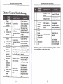
GSilFilTERS(rcIGTIM5IT.
3.7 Terperafure a|arm.........,..,.......
GSM POWER SOCKET USER MANUAL
---...27
3.8 SMS nofficalion upon the socket output changirq........---_---.-..-.2g
1. Purchase a GSM SIM card (mobile phone. card) from
GSM network service provider and install it in the
socket. This Slt card number is referred as GSM power
Socket number on this brochure.
2. The user needs to activate the Caller lD Presentation
function of SIM card, and deactivate PIN code of the
Slm. Contact with GSM network service provider for
support,
3. Change the origanal password at the beginning use. Be
3.9 SMS notification upon external power supply changing...-.........29
tone..........
..............................29
3.11 Check status...............
............30
3.12 Resetting the socket.........
...............................32
Chapter 4 Maintenance....
................_..33
Chapter 5 General Troubleshooting
.............................34
Chapter 6 Main Technical Parameters
,........................36
Appendix: SMS commands |ist.....................
................37
3.10 'Beep" warning
sure to keep the password and SIM card number
secret. Do not disclose this information to anyone
other than the authorized users in order to ensure your
safety.
For your safety
r
r
r
r
r
r
r
This socket was designed for home or office use. Do not use it on
the elechical appliance which is for industry or business operation,
for example, iatrical appliances, large heaters and refrigerates.
Before using this socket, make sure that the mobile phones can be
used well in the area, otheruise, do not put this socket into
operation.
The powerconsumption ofthe appliances connected with the socket
cannot exceed 3000W and the current cannot exceed 16A.
The electrical appliance which power consumption is higher than
1 500W must be groundedDo not make two plugs of socket short circuit.
Do not touch the socketjack by any metal objects or hand.
This socket was designed for indoor use. Don't use it in wet,
chemically aggressive or dusty environment.
5
GSM POWER SOCKET USER MANUAL
r
r
Do not open the case unless maintenance needed.
Elo not keep shaking or fall down this socket, otherwise it can be
damaged.
.
GSM POWER SOCKET USER MANUAL
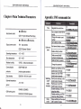
Chapter 1 Features and accessories
This socket is a wireless signal transmission socket. Keep it away
r
from electronic equipment likely to interfere with the wireless signals,
in order to avoid signals interference.
Switch off this socket and mobile phone when entering areas
marked "Explosive", "Might explode", "Closed wireless transceiver
r
r
r
sockets" etc.
Do not cast this socket in a fire, as this may cause explosion.
This socket should only be operated from power approved by the
socket manufacturer. The use of any other types of power may
damage the socket.
Keep the socket and its accessories out ofthe children reach.
Exception clause
'1.
We operate on a policy of continuous development. We reserve the
right to make changes and improvements to any of the sockets
described in this document without prior notice,
2. We don't guarantee for the document veracity, reliability or any
content except regulate in proper laws. lncluding no guarantee for
socket suitable market or suitable area promise.
3. We hold no responsibility for the illegal use of this socket.
4. We hold no responsibility for any loss of income or any special,
1.1 Main function
r
r
r
r
r
r
r
r
r
r
reliability or contents of this document. We reserve the right to revise
this document or withdraw it at any time without prior notice.
I
I
t
Relay: 30A/250V relay with two working status power on/off for
output outlet.
M button: To manual control output power on/off.
Delayed mntrol socket output.
Auto operates by preset sbhedule: Fixing{ime control output power
on/off.
External temperature sensor supported: Send environmental
temperature SMS to mobile phone.
Auto operates by temperature: Available for power control of the
heating or refrigeration plant, to keep the environmental temperature
r
incidental, consequential or indirect damages howsoever caused.
5. The contents of this document are provided "as is'. Except as
required by applicable law, no warranties of any kind, either
expi6ssed or implied, including, .but not limited to the accuracy,
This socket uses a GSM SIM card.
Remotely operale by SMS command: The socket be controlled and
set by sending SMS commands.
lnput: 100V-250V/50H2.
Output: Max.'16Afor long{uration operation.
r
r
r
within presetting range or at fixed temperature value.
SMS alarm when temperature rapid-changing or reaching the
pre-set value: When it detects the rapid-changing or the reach of
pre-set alert value of surroundings temperature, it can auto-send the
SMS alarm message to master's mobile phone.
Support 5 mobile phone users.
Autotime-synchronization.
SMS notification upon external power source changing.
G[il
GSM POWER SOCKET USER MANUAL
FOUYER SOCXET USER MANUAL
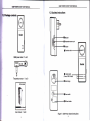
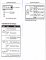
1.3 Sockets
Egeconbnts
instructions
bu[on
O
GSM powersocket
Eleclrical oufler
('l unit)
Socket
Temperature sensor (1 unit),
Usermanual (1 unit)
Figure 1: GSM Power Socket instructions
9
GSM POWER SOCKET USER MANUAL
GSM POWER SOCKET USER MANUAL
One time
Temperature sensor
-re
Standard 3.5mm interiae
(put into 2 of Figurel)
"Beep"
warning tone
(Default
turning off)
The socket outlet changes
power
suDolv status.
Several
GSM Power Socket lost external
times
oower suoolv
GSM Power Socket
Long Beep
is
successfullY
or it is
to its factory
register GSM network,
successfully reset
sFJtinos-
Figure 2: Temperature sensor lnstruction
Note: The "Beep" warning tone can be tum on or tum off by SMS
command. Refer to Chapter 3.9 for details.
1.4 Light indicator and "Beep" waming tone
No power supply input
Power
(Green) light
Has power supply input
Not installed SIM card, or the power
switch of socket is "OFF".
GSM (Blue)
light
Be busy or searching GSM network.
Successfully load to GSM network.
Output (Red)
light
The socket outlet has power supply.
The socket outlet cuts power supply.
GSil
FOYVER SOCKET USER MANUAL
GSM POWER SOCKET USER MANUAL
4. M button
(See 3 on Figurel) can be pressed for about 0.5
second to
switch on or off the output of socket.
2 Quick start
After adding user numbers to the socket, users can
send SMS
command to control the power supply output. (Refer
to Chapter 3.2)
E[
the SIU card and temperature sensor
Trrn the power switch to ,,OFF,, position.
laeen Oe screw and open the socket,s SIM cover; you
will see a
$M
card holder.
hrsh the metallic cover of the holder to ,,OpEN,
direction and open
tle SIM card holder.
Rrt the SIM card on the card holdel ensuring
that the
beveled
comer is toward the beveled corner of the StU
noiOer anJ the golden
@ntact area is facing downwards.
Cover
back the metallic cover and push it to .LOCK,,direction.
The
SIM card will be fixed in the holder.
Screw the SIM cover back.
lnsert the temperature sensor into the l/O port
unfil it is seized.
Power off:
1. Turn the power switch to "Otr position. The blue light turns
off.
2. The socket ouflet can work as a normal power socket. GSM power
Socket can not be controlled by SMS commands.
M button is
disabled.
A
Not"'
1.
2.
lf the GSM indicator light is not conslant lights, which impty
the SIM card working abnormally, all functions of this socket
are invalid.
Check GSM network signal of the using place:
The GSM network's signal shength may affect the socket
feature. Therefore, before using, the user should ensure
o
that GSM Power Socket is used in an area with a strong
o
GSM network signal.
For the frst time use, the user should perform a test_run
by sending SMS to the socket. This allows the user to
GSM Power on/ off
check the GSM network connection of the socket.
on:
Tum the power switch to ,,On,, position (See
7 on Figurel ).
power
Pft;g
the GSM
Fgure'l).
Socket
in an AC power slocket'(See 6
on
light wiil be flashing stowty for about 20
seconds, then btue
$.
?,ra
,Beep"
rgnr De on constanfly and
,,Beep,,
a long
tone can be heard (if
mming tone is enabled).
t default state of the socket ouflet is no power supply
output.
lnsert the prug of erectronic appriance in
the GSM power
electrical ouflet (See 4 on Figurel).
t2
2.3 Add a Master number to the socket
The user must edit and send the following SMS to socket via
his/her
mobile phone (the phone number will be the Master number)
in order to:
Add a Master number to the socket: #00#
socket
@ Successful SMS reply
Welcome to use GSM power Socket.
Your Password is:1234.
13
fr
i
G(il F(TER
S(rcl(ET T'SER IIAIf,,tAL
GSM POWER SOCKET USER MANUAL
2.tllbtrgrldmdtrne
E *cmno
2.6 External power suppty notification
F GStt Po*er Socket is being used for the first time, or it has been
r$
il*r
reset, &e
user must adjust the socket time according to
the qrnent time of SMS center_ Otherwise, GSM power Socket will
use the original time from 00:00:00, 1"t.Jan.2004.
I
I
i
i
i
i
f Iethod
The taster user sends following SMS message in order
Regul#thesockettlme: #152#Slt@rdilumM
o
to:
(f)
The SlilCardNumber should be the SIM card number of eSM
Power Socket .
@ Successful SMS reply
The socket current time is yyyylmm/dd hh:mm.
2.5 Socket output switching on/off
N
Method
llethod
l,
tethod 2:
The taster
To press
t
button 0.5second (See 3 on Figurel).
user sends following SMS message to socket in order to:
$Mtch on the socketoutput:
$rlbh offthe eocket output:
I
GSM Power Socket will notify the user when the external power changes.
a SMS
notification will be sent if the SIM card is available:
The "Beep, Beep..." tones will be heart (if enabled), also
Lost extemal power supply:
lf the plug of GSM power Socket is disconnected from extemal AC power
or lost of the AC power occurs, all operating on GSM power Socket is
de-activated, including M button and all SMS @mmands. GSM power
Socket will notify the user "Main electricity supply
Temp:*.,.
lost
Resume external pouaer supptyr:
lf the AC power of GSM power Socket is available again, the SMS
notification will be sent to the user, i.e.' Main electricity supply restore
Status:ONiOFF
Temp:**"
When the external power supply is resumed, the output of GSM power
Socket will keep its previous working stafus. For example, if the output is
switched on before the extemal porver supply cut off, the output will be
switched on when the extemal power supply is resumed.
lf the power supply is switched on and off frequenfly, GSM power Socket
will send reminding SMS messages.
The SMS notification upon extemal power supply changing can be
disabled. (Refer to Chapter 3.8)
#01#
#02#
Successful SiIS reply
..,Status: ONiOFF
Temp:**
Temp control: function ON/OFF
Schedule control: function ONiOFF
Delay control: function OFF
ti
ii
li
t4
ll
l.
GSM POWER SOCKET USER MANUAL
GSM POWER SOCKET USER MANUAL
o
Chapter 3 Advanced settings
A
3.1 Define the users
GSM Power Socket will reply to the user after
command.
Note
.
The 'H" symbol must not be ignored when typing an SMS
.
command.
No allow any space within the mmmands.
3.1.3 Add a master
3.1.'l User authorization level
All the settings of GSM power Socket can be set or adjusted via a SMS
lf GSM Power Socket is being used for the first time, or cSM power
to factory settings, the Master user,s
number must be programmed into the socket.
Socket has been reset
ffi
Uaster user:
Only one Master user has authorization to use all features of GSM
Power Socket.
ln order to enable all the functions on the socket, the Master user
must store his/ her mobile number in the socket,s memory. Only one
Master's mobile number (Master number) is allo-wed for a socket.
I
I
i:
t,
There are four Family users have authorization
;
commands of switch on or cut off the socket output.
li'
The other mobile phone users have no authorization to use GSM
r
Power Socket
number) in order to:
t
@ Failed SMS reply
lf a user tries to add another Master user again, GSM power
Socket will send a notification via SMS stating ,,The master user
already exists.". The Master number should be changed. (Refer
to Chapter 3.1 .4)
3.1.2 Abqut the SMS Command
.
o
f o
t o
I
o
t
g
I
t
(21
Welcome to use GSM Power Socket.
Your Password is:1 234..
I
r
masternumbertothesocket: #00#
@ Successful SMS reply
to use two
.
Method
The user must edit and send the following SMS to socket via
his/her mobile phone (the phone number will be the Master
Add a
Family users:
i
numberto the socket
@ Description
command.
There are two mobile phone user controlling levels:
i
it receives the SMS
Master user's SMS command format: #code#content#.
Family users'SMS command format: #code#content#oassword#.
The password must be a four-digit number.
The original password is 1234.
The maximum digits that are allows for the phone number is sixteen.
t6
3.1.4 Change the master number
ffi
Method
Method 1:
The Master user sends following SMS message in order to:
Change the master user,s numberi #14#NewnasterNumber (3)
t7
GSM POWER SOCKET USER MANUAL
.
iler*astwrlamfu
GSM POWER SOCKET USER MANUAL
should be the new Master user's
mobile phone number.
3.1.7 Delete famlly number
ffi
Ie&od2:
GSM Power Socket should be reset to factory settings to remove
old Master number before setting the new one. (Refer to Chapter
3.11)
Method
The
taster
#11
I
Dclete all family
Successful SMS reply
New master number set successfully.
Successful SMS reply will be sent to the new Master user. Then
the old Mastor user's number will not be able to control GSM
Power Socket anymore.
3.l.5Add
a
#'11#
(7)
(8)
@ Failed SiIS rcply
#-..*..# The family number does not exist.
Method
#06#FamiWlamM
3.2 Ghange paEsword
ffi
The ilaster user sends following SMS message in order to:
Change the password: #O4#Oldnssvot#l{ewnss*ot*
The Fssnmnlis a four digit number.
The oiginal passtnrdis 1234.
@ Successful SMS reply
(4)
#06#Famllutlumbql#...#FamilvMamber4
(S)
phone
(e)
New password is ****.
Add several famlly numbers:
FamilyNambr should be the Family user's mobile
Method
.
.
The Master user sends following SMS message in order to:
Add a famlly number:
.
3#Familtltarrrffi#...#FamiluMambs&
numbers.
(6)
@ Successful SMS rcply
family number
Up lo 4 famllyusers' number can be stored on one socket.
Familyr users have the authority to send SMS command to switch on or
cut off the GSM Power Socket output. The family users should remember
and safeguard the socket's SIM number.
ffi
user sends following SMS message in order to:
Delete a famlly numbor: #'113#futnllul{amW
Delete several family numbee slmultaneously:
3.3 Switching on/ofithe socket output manually
f,E Description
number.
.
@ SucE6ssful SMS rcply
3.1.6 Gheck family user's number
Refer to Chapter 3.10 Check status.
t8
.
When the socket output is switching on, GSM Power Socket offers
power supply for electronic appliance which being connected with it;
the red indicator light is lighted constantly. Othenrvise, GSM Power
Socket has no power supply for electronic appliance and the red light
is turned off.
Note: lf the socket output status is changed manually (including
il button, sending SMS, making phone call), the preset
timing, delaying or temperature control of the socket will be invalid
pressing the
l9
GSM POWER SOCKET USER MANUAL
GSM POWER SOCKET USER MANUAL
automatically and a SMS notification message will be sent to the
be switched on or cut off automatically when the user hears the
ring tone in the phone. The calling will be hung up automatically if
the user doesn't hang up the call.
Master, but the setting time range and temperature range
parameters will be saved until GSM power Socket is reset to factory
settings.
ffi
The
3.3.1 Switching on/off by SMS
ffi
The Master user sends following SMS message in order to:
Switch on the socket output manually:
(10)
Gut off the socket output manually:
(11)
The Family users send following SMS message in order to:
Switch on the socket output manually:
(121
Cut off the soiket output manually:
(13)
Password should be 4 digits password number. Default 1234.
SMS reply will be also sent to Master user when Family users use
#01#
ffi2#
these two commands to change the socket output successfully.
SMS reply
Status: ON/OFF
Temp:**
Temp control: function ON/OFF
Schedule control: function ON/OFF
Delay control: function ON/OFF
I
orfirt
by calling:
(r4)
(r5)
Successtul StS tEply
Control the socket power output status by calling activated
/de-activated.
3.4 Delayedeiritch on/ofithe socket output
f,E Descrlption
.
.
.
The output of GSM Power Socket can be set to delay switch on or off
for a period with SMS commands.
When the "delayed-switch on/off the socket" function is applied, the
preset'timed switch on the output" function will be invalid at once.
When the "delayed switch on the socket" command is received and
Keep press M bufton on the GSM power Socket for half a second.
if the socket output is switched on, the socket output will be switched
off immediately and be switch on again as the setting delayed time is
reaching. Contrarily, if the socket output is switched off, the output
The OUTPUT indecator light will turn on or off to indicate that
will remain switching off until the setting delayed time is reaching.
GQM Power Socket output is switching on or off.
Afther switching on the output, the following SMS reply will be sent:
Status: ON
Delay control: function OFF
When the "delayed switch off the socket" command is received and if
the the socket output is switched on, the socket output will remain
the switch on state and be switched off as the setting delayed time is
reaching. lf the socket output is switched off, it will be switched on
3.3.2 Switching on/off by M button
.
user sends following SMS message in order to:
#18#1#
Disable swltching onlotrthe ofin by caillng (Defautt):
#lW
{fr1#Passwor#
ifr2#Passwor#
O Successful
taster
Enable swltching onlortrthe
Method
.
o
illethod
The SMS reply is same with Chapter 3.2.1.
3.3.3 Switching on/off by calling
&tr Description
lf the Master user calls GSM Power Socket , the socket output will
.
GSM PoWER SocKET USER
GSM POWER SOCKET USER MANUAL
immediately and be switch off again when reaching the setting
delayed time. After switching off the socket output, the following
The ilaster user sends following SMS message in order
Enable timlng switch on the
@ Successtul SMS
llethod
The ilaster user sends following SMS message in order to:
#138#1#tlnaffi
Delay switching off the ouQut after a caltaln mlnutes:
.
o
#'!3g#ffitlruH
lllnutes is 0, the
"delayed switch on/off the socket" function
will be invalid, but the current output status won't be changed.
I
I
I
I
i
j
output
I
]
3.5 Timed switching on the socket output
3.5.1 Enable timing switching on the output
Descrlption
The output of GSM Power Socket can be set to switch on for a
duration and then be switch off after the duration.
lf the socket output status is changed manually (including pressing
t button, sending SMS and making phone call), the preset timing,
delaying or temperature control of the socket will be invalid
automatically, but the setting time range parameters will be saved
until cSM Power Socket is reset to factory settings. lf these functions
need to be restarted, the following SMS commands must be set:
Timing #128#1#, Temperature control #159#1#, "delayed switch
on/off the socket" commands need to be reset.
I
]
After successful setting of time duration to switch on the socket
output, the schedule parameter will be saved on the socket until
Status: ON/OFF
*
Output will switch offlon after minutes.
o
I
reply are all 0, it means the time duration
settings.
3.5.2 Set time perlod b sdtc{r on the output
Q Description
@ Successtul SMS reply
E
o
S)
automatically according to the schedule
(r7)
fillnulesare time parameters, its range is 0-720,
When
(f
SMS
has not been set. (Refer
to
Then GSM Power Socket will keep switching on or off the
(rO)
I
to:
lf the value of the " WorkDa)1 9ai77mq EndTime" on the
3.4.2)
Delay switching on the output after a cerlaln minutes:
I
I
ffi Method
output: #128#1#
rcply
Schedule control: function ON
WorkDaJ4 StaiTime-EndTime
SMS reply will be sent:
Status: OFF
Delay control: function OFF
ffi
MANUAL
GSM Power Socket is reset to factory settings.
But the "timed switch on the output" feature is applied only when
command 17 be set.
ffi
Method
The ilaster user sends following SMS message in order to:
Set time perlod to switch on the output:
o
#12wlWDa*Sbrtfim*End1im#
WorlrDay. one digit, the values lie in the range of "0" to "8".
The following table contains the descriptions of each value:
Value
0
1
2
3
(i9)
GSM POWER SOCKET USER MANUAL
5
Friday
6
Saturday
Everyday
7
.
o
GSM POWER SOCKET USER MANUAL
switch on/off the socket' functions, the socket will control to switch
on or cut off the output according to temperature setting.
lf users open the "timed switch on the socket" or "delayed switch
on/off the socket" functions, the temperature control function will only
be valid when power output is switch on (including timed switch on
or delayed switch on time period).
For example: GSM Power Societ is used for the power control of the
StaftTime and EndTime: Be consists of 4 digits (hh:mm) and works
on a 24 hour clock. The StaftTime and EndTime should be in the
same day, and the EndTime must be later than StartTime.
heating apparatus. lf users set the socket output on when indoor
temperature is bellow 20 degrees and off when indoor temperature
is above 28 degrees. Meanwhile, users set the GSM Power Socket
output is on from 9am to Spm. ln this case, the socket will control to
switch on or off the ouput according to indoor temperature
automatically from gam to Spm duration.
The socket output will switch on at the StaftTime and cut off at the
EndTime.
o For
example: #'l2gt1ffiOOC#213W
, 0000
means
time
00:00(hh:mm)AM, 2130 means time 9:30PM.
@ Successful SMS reply
Schedule control: function ON/OFF
WorkDay, StartTime-Endlime
3.5.3 Disable timing switching on the output
ffi
Method
The Master user sends following SMS message in order to:
(20)
Disable timing switch on the output:
#128#0#
O
Successful SMS reply
Schedule control: function OFF
WorkD ay, Stafi Ti me- E ndTi me.
ffi
Method
The Master user sends following SMS message in order to:
Enable auto-control the output by temperature: #'159#1# (21)
@ Successful SMS reply
Status: ON/OFF
Temp control: function ON
Temp: *"
Mode: Heating/Cooling
Range: Lowlemp - HighTemp
Then cSM Power Socket can switch on or off the output
automatically according to the temperature range setting.
3.6 Auto-control the socket output by temperature
3.6.1. Enable
auto-controlled by temperature
@ Description
o
.
The external temperature sensor must be inserted into the l/O port
of GSM Power Socket. The output status of the socket can be
3.6.2 Set temperature range to switch on/off the output
E0 Description
After successful setting of temperature range, the temperature
parameter will be saved on the socket until GSM Power Socket is
reset to factory settings.
controlled by the environmental temperature automatically.
lf
users don't open the "timed switch on the socket" or "delayed
But the 'Auto-controlled by temperature" feature is applied only
24
25
GSM POWER SOCKET USER MANUAL
GSM POWER SOCKET USER MANUAL
Dlsable auto+ontrol the output by temperature:
Successtul SMS reply
when command 20 be set.
ffi
I
Method
The liaster user sends following SMS message in order to:
Set temperaturc range to switch on/ofi the output:
.
.
.
.
.
#159#to#Lov7$rfrHiohTdrrd
frlo&is
Example 1: set commands: #159t0#10#20#, if the environmental
temperature is 5 degrees (bellow the limitation of '10 degrees in the
command), the socket output will be switched on to power heating
apparatus; and if the environmental temperature is 24 degrees
(above the limitation of 20 degrees in the command), the socket
output will be switched off and the heating apparatus stops working;
Example 2: set commands: #15#'l#10#20#, if the environmental
temperature is 26 degrees (above the limitation of 20 degrees in the
command), the socket output will be switched on to power cooling
apparatus; and when the environmental temperature is 7 degrees
(bellow the limitation
of 10 degrees in the command), the socket
output will be off, cooling apparatus stops working.
@ Successful SMS rcply
Status: ON/OFF
Temp control: function ON/OFF
Temp: **
Mode: Heating/Cooling
Range: LowTemp - HighTemp
3.6.3 Disable auto.controlled by temperaturc
ffi
l21l
constant temperature control will be actived.
Temperature unit is degree Celsius.
Method
The liaster user sends following SMS message in order to:
(23)
Status: ON/OFF
Temp control: function OFF
Temp: **
Mode: Heating/Cooling
Range: LowTemp - HighTemp
the control selection:
For coldness, mode=1. For warmness, mode=O.
Lovlbmp and HlghTanp means temperature value, the range is
-10 to 50 centigrade degree, if LovTenp equals to HlghTeDrp,
#159#0#
3.7 Temperature alarm
3.7.1 Over-temperature
E
alam
Descrlptlon
A range oftemperature can be pre-set onto the socket. ln this case,
sunoundings temperature is detected out of the pre-set
temperature range, the GSM Power Socket will auto-send the SMS
alarm message to master's mobile phone.
This feature depends on the temperature sensor-
if the
ffi
Method
The llaster user sends following SMS message in order to:
Enable over4empeEturc alam:.
(Al
Setlimiteofbmpcrat!rci #17o#MinTemdMaxTemd
(25)
#170#1#
.
lllnTemp and taxTemp: The values can be set within the range of
-10 to 50 centigrade degree.
Default lllnTemp is 20 and MaxTemp is 30 centigrade degree.
Disable the alam upon golng beyond llmlts temperaturel
@ successtut sMS
reply
#170#0#
Temperature alert: function ON/OFF
Min Temp.:**
Max Temp.: **.
(26)
GSM POWER SOCKET USER MANUAL
3.7.2 Temperaturc rapid.changing
E
GSM POWER SOCKET USER MANUAL
alam
@ Successtul SMS rcply
A time period value and temperature changing value can be pre-set
onto the socket. ln this case, if the surroundings temperature change
to the pre-set value within the pre-set time period, a SMS alarm
message will be auto-sent to master's mobile phone.
This feature depends on the temperature sensor.
ffi
Set no SMS notification when socket output changed.
Set SMS notification once socket output changed.
Descrlption
Method
The Master user sends following SMS message in order to:
Enable the temperaturc rapid changlng alarm:
Set time period and temperaturc changlng value:
#160#1#
#160#TemfrTimd
.
.
.
3.9 SMS notification upon e:dernal power supply
changing
EB Description
GSM Power Socket will default notify the user when the state of the
external power supply is changed with a SMS notification. For
(271
example:
Main electricity supply lost
Temp:**
(28)
Tsmp: The values lie in the range of 1 to 50 centigrade degree.
Timel The values lie in the range of 1 to 300 minutes.
Default Temp is 2 degree and Time is 1 minute.
Disable the temperature rapid changlng
#160#0# (29)
@ Successful SMS reply
ffi
Descrlptlon
GSM Power Socket will default notify the user when the state of the
socket output is changed with a SMS notification. The Master user
can enable/disable this SMS notification.
Methird
#11#1#
2*
(32)
(No) SMS notification upon main electricity supply changing.
3.10 "Beep" waming tone
Descrifilon
A "Beep" warning tone will be sounded if the work state of GSM Power
Socket is changed. The "Beep" warning tone is default turning off.
taster user can enable it by sending SMS command.
(30)
The
SilS notification upon the socket output changing:
#11#0#
#1X1#
St[S notlficadon upon lhe power supplyt changlng: #12#0# (33)
@ Successful StS nply
No
E
The llaster user sends following SMS message in order to:
SMS notification upon the socket output changing (Default):
No
Method
The ilaster user sends following SMS message in order to set:
SilS notification upon the pmrsupplti clnnglng (Default):
3.8 SMS notification upon the socket output changing
ffi
Main electricity supply restore
Status: ON
Temp:**
The Master user can enable/disable this SMS notification.
alarm:
Fast temperature changing.: function ON/OFF
Delta:**
Time:* minutes
[E
or
(31)
ffi
Method
GSM POWER SOCKET USER MANUAL
GSM POWER SOCKET USER MANUAL
The Master user sends following SMS message in order to:
(34)
Enable the "Beep" warning
(35)
Disaable the "Beep" warning tone
#19#'l#
tone:
(Default): #19#M
SMS message of "Timing switch on the socket" parameters:
Schedule control: function ON/OFF
WorkD ay, Sta rtTi me-E ndTi me.
#159#
Check "Temperature control" parameters:
(40)
After receiving the SMS commands, GSM power Socket will reply one
SMS message of temperature parameters checking:
Status: ONiOFF
@ Successful SMS reply
Beep alarm activated/de-activated.
Temp control: function ON/OFF
Temp: **
Mode: Heating/Cooling
Range: LowTemp - HighTemp
3.11 Gheck status
ffi
Method
The Master user sends following SMS message in order to:
(36)
Check socket operating
After receiving the SMS commands, GSM Power Socket will reply one
status: #O7#
SMS message of socket status checking:
lf "No temperature sensor connected" be received, it means
Check "temperature rapid changing alarm" parameters: #160# (41)
After receiving the SMS commands, GSM Power Socket will reply one
SMS message of parameters. lt means SMS alarm message will be
sent upon the surrounding temperature changes "Delta" centigrade
degree within * minutes:
Status: ON/OFF
TEMP:**
Temp control:function ON/OFF
Schedule control:function ON/OFF
Delay control:function ON/OFF
Fast temperature changing.: function ONiOFF
Delta: *
'llme: * minutes
status: #000#
(37)
Check socket output
After receiving the SMS commands, GSM Power Socket will reply one
SMS message of socket output status:
Status: ON
Temp:23.
Check "delayed switch on/offthe socket" parameters: #138# (38)
After receiving the SMS commands, GSM Power Socket will reply one
SMS message of "Delayed switch on/off the socket" parameters
checking:
Status: ON/OFF
Output will switch off/on after "* minutes.
GSM
Power Socket cannot detect the temperature sensor. User needs to
check if the temperature sensor is inserted to the l/O port.
#128#
(39)
Check "Timing switch on the socket" parameters:
After receiving the SMS commands, GSM Power Socket will reply one
#170#
Check "over-temperature alarm limits" parameters:
l42l
After receiving the SMS commands, GSM power Socket will reply one
SMS message of parameters. lt means SMS alarm message will be
sent upon temperature reaches MinTemp or MaxTemp centigrade
degree:
Temperature alert: function OFF
Min Temp.: **
Max Temp.: **
GSM POWER SOCKET USER MANUAL
GSM POWER SOCKET USER MANUAL
3.12 Resetting the socket
El
o
Description
This function resets all programmed settings to their original values,
including cleaning
user number, timing parameter and
temperature parameter.
Chapter 4 Maintenance
all
. lf the setting status is wrong or the malfunctions can't be
corrected, users can restore the socket to its original status to make
it work normally.
A Note
lf
Store and use the remote socket in suitable temperature.
This function needs to be used carefully as it also erases all setting
ffi
GSM Power Socket does not in use for long time, it
should be powered off.
values.
Too high or too low temperature will likely to damage the
Method
socket.
Method 1: Press the side M button of the device for 5 seconds.
Method 2: The Master user sends following SMS message
Power
Socket in order to:
Reset the
socket:
O Successful
#08#
to
GSM
ib accessories
Try to keep the GSM Power Socket and all
dry. Do not store and use it in the bathroom, or other
(43)
SMS reply
place with high humidity. Do not allow pour water or other
Reset the socket to factory setting successfully.
A long "Beep" tone (if enabled) will be heard and it means resetting
the socket successfully.
liquids into the socket, otherwise,
it
might
cause
malfunctions.
.
Do not store and use the socket in dusty.
Do not use alcohol, acetone and other similar solvents to
clean it. Wipe it with soft-wet cloth.
Do not attempt to open it except as instructed. lf the
socket does not work normally, try to resolve it as the
guide of the "general troubleshooting", if to the problem
can not be solved, contact with the dealer immediately.
33
GSM POWER SOCKET USER MANUAL
GSM POWER SOCKET USER MANUAL
Chapter 5 General Troubleshooting
Power
indicator light
turns off
GSM
indicator light
turns off
Check GSM Power
Socket 's external AC
Can't find oi identify
the SIM card.
The power switch is
OFF.
No power input.
The power switch is
OFF.
Caller lD
presentation do not
active, insufficient
fee of the SIM card.
GSM Power Socket
work abnormally.
After power
on the
socket, GSM
indicator
keeps
SIM card PIN code
actives.
Network signal
weak or network
busy.
Other master is
already set in the
socket.
SIM card no install
properly: Power off
the socket and check
it again.
Power on the socketCheck GSM Power
Socket's external AC
power is available.
Power on the socket.
Contact network
.provider
to active SIM
card function. Pay for
the card.
Switch off the power,
check SIM card, or
reset factory setting.
lf mobile phone's
signal is weak too,
place the socket at
other place with
strong signal and try
lnvalid command.
No
authorization
user
Change Master
number or recover to
factory default setting.
Refer to the user
manual.
Use the Master
mobile phone to try
the command
Note: lf the problem can't be solved with above guidelines, contact to
your local distributor or after service center.
GSM POWER SOCKET USER MANUAL
Chapter 6 Main Technical Parameters
GSM POWER SOCKET USER MANUAL
Appendix: SNIS commands list
Time
1go-25ovlsonz,
Add a master number to the
socket
Change the master user's
lnput power socket
CEE717 hybrid Schuko/French plug
number
Add a familv number
too- zSovlso Hz, zfovtoonlsos;,
Output power
socket 'l64
long-duration,
CEET/4 German "Schuko"
Define the
USETS
Operatingtemperature -10.C-+50C
temperature
Relativehumidity
Communication
protocols
Data interface
Store
10-90%,withoutcondensation
(including datet operation)
(1)
#152*ASlMCardNumber#
(2)#00#
(3l tl{#.|dewMastet
Number#
A\#O6#FamilvNumber#
(s)W!!yNsmberT
#...#FamilvNumbar4ll
(6)
#113#FamilvNumber#
Flfr?#ram!!flsnber
7# #FamilvNumhar&
(8) #11 3#
(9)#04#Oldpasswor#
Newoassword#
Master user switches on the
(1 0) #01#
socket outout manuallv
Master user cuts off the
socket orrtnrrt manilellv
Family user switches on the
(12)#01#Passwor#
sockel outDut manuallv
Family user cuts off the
(13)#02#Passwor#
sod<el outnrrt manr rallv
Enabb srvitching on/off the
(14)#1#1#
oubut bv callino
Disable svitcfiing on/off the
(1 5) #1 8#0#
oulnut bv callim lDe-farritl
Delay svitcfiing on the oupul
(16)_#'t38#1,fiEitsb#
after a cedain minutes
('t1wi
cSM SIM 1.8V/3.0V socket
sensor
Delete a family number
Change the password
GSM PHASE 2i2+
_10c-50c
Add several family numbers
Delete several family
numbers simultaneouslv
Delete all familv numbers
-20C-+60C
Switching
External temperature
Regulate the socket time
on/of
ou$ut
manually
GSM8sO, EGSMgOO,
GSM working band
DCS'l 800,PCS'1900 Optionat
Delay
control
37
GSM POWER SOCKET USER MANUAL
GSM POWER SOCKET USER MANUAL
Timing
control
Temperatu
re control
Delay switching off the output
after a certain minutes
Enable timing switch on the
outout
Set time period to switch on
the outout
Disable timing switch on the
orrlnrrt
Enable auto-control the
nr rlnr rf hv femnaretl rre
(17)-#138tfr#Mjtsb#.
SMS notification upon the
power supply changing
(18) #128#1#
No SMS notification upon the
(19) #129#Wo*Dav#
Enable the "Beep" warning
tone
Set temperature range to
switch on/off the outDut
Disable auto-control the
output by temperature
(22W!:Mocl#LowTe
Enable the over-temperature
alarm
Overtemperatur
e alarm
Temperatu
re rapidchanging
",::
SMS
notification
Set limits of temperature
Disable the over-temperature
alarm
Enable the temperature
rapid-chanqinq alarm
Set time period and
temoerature chanoino value
StafiTim&EndTime#
(20\#128#0#
(21) #159#1#
Check socket operating
status
mdHiohTemo#
(23)#15e#0#
Check "llmed switch on the
(24)#170#1#
(25) #170#MinTemp#
MaxTemd
Check "temperature
rapid-changing alarm"
(26) #170#0#
(27)#160#1#
(28)#16O#TemdTim&
Disable the temperature
rapid-changing alarm
(2e) #160#0#
SMS notification upon the
socket output changing
(Default)
(3O)#11#1#
No SMS notification upon the
(31) #11#O#
socket outout chanoino
Reset the socket
(34) #19#1#