1
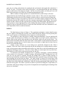
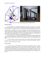
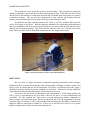
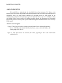
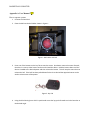
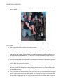
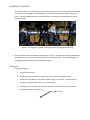
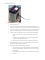
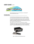
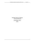
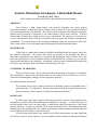
Assistive Wheelchair Attachment: A Basketball Shooter
Team Rocky Ball Throa:
Brad Arnold, James Hayes, Bob Herpy, Bob Meholif, Schuyler Redding
ABSTRACT
Trent Glaze is a high school student with muscular dystrophy who enjoys playing
wheelchair basketball. Despite his desire to compete in these games, he is only capable of a limited
level of participation due to his disability. His particular form of muscular dystrophy has caused his
shoulder and leg muscles to deteriorate so he cannot stand or lift his arms vertically. With his
limited range of motion he is unable to shoot or pass a basketball. The purpose of our project was
to create a mechanism which would allow somebody with very limited arm motion to aim and shoot
a basketball. This report discusses the launching mechanism which was developed to allow Mr.
Glaze to take an active role in shooting and passing during wheelchair basketball games.
BACKGROUND
Trent Glaze is a high school student at Fairfield Union High School in Lancaster, Ohio who
has Muscular Dystrophy. This disease has caused the muscles in his shoulders and hips to
deteriorate causing him to be confined to a wheelchair and making him unable to lift his arms. Mr.
Glaze has participated in both wheelchair football and basketball for a number of years but has
limited participation due to his disability. His inability to shoot or pass a basketball has caused him
to decide to not participate in the wheelchair basketball league this year.
STATEMENT OF PROBLEM
There is a need to create a device which will aid in the shooting and passing of a basketball.
This would allow a person with a disability similar to our customer to take a more active role in a
wheelchair basketball game, making it a more enjoyable experience.
Our defined problem statement is:
The customer needs a device which will aid him in shooting a junior size basketball from 3
point range into a 10’ high basket. The most important factor in the design of this product is
that the customer is able to operate it safely and completely by himself.
RATIONALE
In order to meet Mr. Glaze’s needs, the final design had to be safe for all participants and as
automated as possible while still maintaining the challenges of the game. To ensure the safety of
the final product, there can be no sharp edges or pinch points and all moving parts of the design
must be enclosed. To make sure that Mr. Glaze could operate the device, the loading and release
mechanisms for the launcher had to be completely automated, and the aiming mechanism either had
to be designed to his disability or automated as well.
Several design specifications were added on top of these requirements, the most significant
of which were the size, speed, and cost. To create a product which could be used during a basketball
BASKETBALL SHOOTER
game, the size of the product had to be considered and was limited to the length of his wheelchair, 3
ft, and 2 ft wide. To operate at the speed of the game, it was determined that the entire shooting
process could take no more than 10 seconds. For the cost of the product, an ideal goal was set at
$400 with a maximum cost of $800 for all manufacturing and parts costs.
While a number of design options were considered for the overall concept, it became
apparent that the only feasible design would be to create a sidecar. There were two major factors
contributing to this decision, the first of which was that in order to create the necessary thrust the
design would be too large to fit on his lap. If the device was made compact enough to use from the
lap position, then the ball would fail to meet the customer requirement of shot distance. The second
reason was that a sidecar provides a greater factor of safety to the final product. Having the device
on the ground, it removes pinch points as well as falling and aiming accidents. With the device
acting as a side car, the ball will always be shot in the same direction as the user orientation as well
as be impossible to fall over and hurt someone.
DESIGN
The final design is shown in Figure 1. The propulsion mechanism is elastic bands because
they are capable of providing the necessary force without having the danger of moving metal parts,
in the case of springs, or of maintaining an air compressor on the mechanism.
The operation is a three step process: loading, aiming and launching. The user loads the ball
into the guide rails and presses a button on a remote control to activate a motor connected to a
spindle which winds up the cable attached to the ball holder which will pull on the elastic. The
motor will not freewheel under the load of the elastic so the launcher can be locked into the desired
load position, ranging from low load for shots close to the basket, to high loads for shots from as
long as 20 feet from the basket.
Aiming is done with the use of an aiming lever specifically designed to Mr. Glaze’s
disability. Since Mr. Glaze is able to push but not pull, the aiming lever is spring loaded to return it
to the vertical position when released but still requires very little force to aim downwards due to the
mechanical advantage of the lever. The device can be held at a certain angle with very little force.
The final device will be able to take shots between 90o and 40o.
To launch the ball another mechanical lever is pushed to disengage a clutch mechanism
which consists of two dog gears, a spindle, bearings, and machined shaft. Pushing the lever will
cause the two dog gears to separate, allowing the spindle that is seated on thrust bearings to
freewheel and release the stretched elastic bands turning all the potential energy into kinetic energy
and propelling the ball towards the basket. The entire design is encased in a metal frame with
strong and shatterproof plastic sheeting for safety and protection. The enclosure prevents damage to
any parts from contact with other wheelchairs, while also keeping participants hands and feet away
from the moving parts. The frame is placed on wheels to prevent exceeding the weight limits of a
wheelchair while also providing an easy mode of transportation and simplifying the mounting of the
device to a wheelchair.
BASKETBALL SHOOTER
Figure 1: System level CAD drawing and photograph of the Basketball Shooter
DEVELOPMENT
The development of a workable and financially viable device occurred in several steps.
After talking with Trent and his coach and considering design goals and requirements, several ideas
were created for how to propel the ball. A force analysis was done to determine the required force
needed to make a 3 point shot on a 10’ basket. To generate 3-D models of possible prototypes we
used the Computer Aided Design (CAD) package Solid Edge. The force data and models were then
used to find the ideal solution that would fit within our budget, provide easy manufacturing and
could match the design specifications. The use of elastic bands stretched by a battery-powered
motor was found to be the best solution for providing the propulsive force.
The rest of the device was designed around the launcher in order to maintain all other design
specifications and requirements. Further testing was done to ensure that the motor purchased could
supply the required loads and that the battery could maintain a charge for an acceptable number of
shots.
A full 3-D model was created to ensure that all of the parts would fit together and the
necessary range of motion could be achieved for aiming. From these final drawings a full scale
prototype was then manufactured for testing.
EVALUATION
A series of tests were performed at several stages of development in order to test the
functionality of the final prototype. The first test was done when the inner launcher was completed
to test whether the launcher would have the power necessary to meet the requirements. This test
was done by aiming the launcher at a wall from fifteen feet away; the distance of a free throw shot.
The launcher was then fully loaded and released with the distance the ball travelled marked. This
test was repeated five times and the ball consistently reached a height of twelve to thirteen feet on
the wall.
BASKETBALL SHOOTER
The second test was to check the accuracy of the launcher. This was done by aiming the
launcher completely vertical and then loading and releasing the ball. If the ball was able to land
directly back in the launcher it would show precision and if it landed in the same place every time it
would show accuracy. This test was also performed five times with the ball landing inside the
launcher twice and bouncing off of the edges of the device the other three times.
The final test was done with the customer, Mr. Glaze, to test if he would be able to use the
device at all stages of the device. With the prototype attached to his wheelchair on the hardwood
floor of a basketball court 20 feet away from the hoop, he was able to load the ball, aim the device
and pull the releasing mechanism. Mr. Glaze shot the ball five times; two of which went in the
hoop. These tests show that the basketball launcher has met the design requirements.
Figure 2: Mr. Glaze preparing to take a shot with the launcher
DISCUSSION
We were able to design and build a basketball launching mechanism which combines
mechanical aid to overcome his handicaps while still providing a challenge to make a basket. This
device is easy to operate and safe for all participants. Our device is not limited just to Mr. Glaze’s
disability but can be used by any person confined to a wheelchair. This device not only fulfills the
requirement of making a basket but restores a dream that was once lost.
Our device met the initial, predetermined cost requirements of $1500 being produced at
$1027 a piece if a production of ten were made. Likewise, the device is easily manufactured and
assembled. We have supplied Mr. Glaze with a user and maintenance manual, (Appendix A)
battery charger, and replacement parts. This device has given Mr. Glaze the opportunity to develop
a broader range of interests as well as showing him that technology has the ability to help him do
things he otherwise would not be capable of. In this way it will allow Mr. Glaze to see a greater
number of options in his future activities and employment.
BASKETBALL SHOOTER
ACKNOWLEDGMENTS
We would like to acknowledge the invaluable help of our instructor, Dr. Kremer, who
tirelessly provided us with the guidance and encouragement needed to see this project through to its
completion. Also, we thank Randy Mulford for providing access to and insight on the
manufacturing equipment and techniques required to build the device. And we would like to thank
our funding sources, most notably the funding provided through the Department of Mechanical
Engineering at Ohio University and a grant awarded through the National Institute for the Severely
Handicapped.
Alternate Text for Figures
Figure 1: This figure shows the computer generated model for the basketball launching
device. This 3D model includes the launcher frame, motor, clutch ball holder, and
aiming hinge of the device.
Figure 2: This figure shows the customer, Mr. Glaze, preparing to take a shot at the basket
with the device.
BASKETBALL SHOOTER
Appendix A: User Manual
How to operate system:
1. Connect to wheel chair 2. Place the ball into the ball holder shown in Figure 1. Figure 1: Ball holder with ball 3. Press one of the buttons on the key fob to start the motor. One button moves the motor forward; the other in reverse, either button can be used to load the device. Hold the button down until the device is loaded to the desired power and then release the button. This will stop the motor but not release the ball. If the ball has been pulled down further than desired the opposite button can be sued to release some of the power. Figure 2: Key Fob 4. Using the black aiming lever which is positioned across the lap, push forward to aim the launcher at the desired angle. BASKETBALL SHOOTER
5. While holding the device at the desired angle with one hand, push down the silver release lever to launch the ball. Figure 3: Demonstration of use of the aiming lever and release lever How it works:
1. The motor is powered by a twelve volt motorcycle battery. 2. To activate the motor a remote key fob can be used to send a signal to the receiving box. 3. Once the motor has been activated it will begin turning. The motor is connected to a gear system and a spindle with a cable. As the motor turns the cable is wrapped around the spindle which in turns pulls the ball holder downward. The ball holder is held up by four elastic bands which are stretched as the ball holder is pulled down. 4. Once the ball holder has been pulled back a desired distance the button is released and the motor stops. The system remains at the pulled back distance because the motor utilizes a worm gear system which will not spin without power. 5. The ball launching system is connected on a shaft which is able to rotate freely. Using the lever which is connected to the top of the ball launching system the device can rotate about this shaft giving the desired angle. 6. In order to launch the ball the releasing lever is pushed. This lever is connected to cable through a wheel. As the wheel is turned the cable is pulled. The other end of the cable is connected to the spindle shaft through a lever. As one end of the lever is pulled by the cable the other end will pull BASKETBALL SHOOTER
the shaft forwards. This motion of the shaft causes the two gears, one on the spindle shaft and one on the motor, to disengage. Once these gears are no longer touching the spindle is able to spin freely. The tensioned elastic causes the ball launcher to move back up and through this motion launches the ball. Figure 4: The dog gears engaged for loading and then disengaged for shooting 7. Once the ball has been launched the releasing lever is let go. This allows for the spring attached to the spindle lever to push the spindle shaft back into its original position. This causes the gears to reengage and allows the device to be loaded once again. Maintenance:
1. Charging the Battery a. Remove plastic barrier. b. Remove the positive lead from the battery. Then remove the negative lead. c. Attach the trickle charger to the leads and then plug in to an outlet. Leave the battery charging for approximately nine hours if fully drained. d. Unplug the trickle charger from the outlet and then remove the clips from the battery. e. Reattach the leads to the battery. Negative Lead
BASKETBALL SHOOTER
Positive Lead
2. Replacing Elastic a. Remove the broken elastic. b. Examine the remaining elastic to figure out which position the elastic broke from. There should be two strands (one loop) running along the inside top of each side of the launcher. c. Thread the new piece of elastic into the empty space. Place one end of the loop through a U‐bolt, then run it behind the guide pin and then thread it through the second U‐bolt. d. To attach the elastic to the ball holder the cable assembly must first be disassembled. i. Loosen the cable crimps that are underneath the ball holder using a size 5/16 wrench. ii. Pull the short end of the loosened cable up through the ball holder so that only one strand is now going through the holder. iii. Pull the cable thimble (metal piece on top of the ball holder) out of the cable. e. Stretch the new elastic piece until it is very thin and then slide the elastic loop into the cable thimble through the opening at the bottom. f.
Reassemble the cable assembly by following the below steps i. Place the cable back around the cable thimble’s track and then thread the loose end of the cable back through the ball holder so that there are now two strands going through it. ii. Pull the elastic through the ball holder until the cable thimble rests tightly on the ball holder. BASKETBALL SHOOTER
iii. Place one of the cable crimps around the two cables coming through the ball holder. Slide the cable crimp up as close to the ball holder as possible and tighten the nuts. Repeat with the second crimp leaving about a half inch in between the two crimps. g. Repeat steps d through f for the other end of the elastic. Visual Safety Inspection:
1. Elastic bands a. Check each elastic band for rips or tears. b. If elastic is damaged replace band before operating. See Maintenance. 2. Cable a. Inspect cable for fraying; specifically around the spindle. b. To replace fraying cable, you will need to get the following items: i. Cable capable of holding 300lbs – Dimension 3/32 (Included) ii. Cable Crimps – Dimension 3/32 (Included) iii. Cable Cutter iv. A Crimper (tool) c. Sever the remaining cable from the device d. Loop the top end of the cable through the ball holder cables and crimp the cable to itself e. Run the cable through the hole in the spindle while pushing the ball holder to the very top. f.
Crimp the cable at the location where the cable exits the spindle. g. Manufactures Recommendation: This is a unique and advanced process. For further information, guidance or onsite assistance; contact Administration at: Greg Kremer ‐ Phone: 740‐593‐1561 ‐ Email: [email protected] or the manufacturer at: [email protected] 3. Wheels a. Check wheels for clogging or dirt. b. If wheels are unable to spin freely clean them off thoroughly with a wet rag. 4. Battery BASKETBALL SHOOTER
a. Look for battery leaking or corrosion. b. If the battery is leaking replace battery before operating.