1
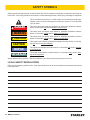
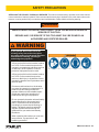
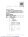
MB05
MOUNTED
HYDRAULIC BREAKER
USER MANUAL
Safety, Operation and Maintenance
© 2014 Stanley Black & Decker, Inc.
New Britain, CT 06053
U.S.A.
70795 2/2015 Ver. 12
DECLARATION OF CONFORMITY
DECLARATION OF CONFORMITY
ÜBEREINSTIMMUNGS-ERKLARUNG
DECLARATION DE CONFORMITE CEE
DECLARACION DE CONFORMIDAD
DICHIARAZIONE DI CONFORMITA
Hydraulic Tools
______________________________________________________________________
I, the undersigned:
Ich, der Unterzeichnende:
Je soussigné:
El abajo firmante:
lo sottoscritto:
Weisbeck, Andy
Surname and First names/Familiennname und Vornamen/Nom et prénom/Nombre y apellido/Cognome e nome
hereby declare that the equipment specified hereunder:
bestätige hiermit, daß erklaren Produkt genannten Werk oder Gerät:
déclare que l’équipement visé ci-dessous:
Por la presente declaro que el equipo se especifica a continuación:
Dichiaro che le apparecchiature specificate di seguito:
1.
Category:
Kategorie:
Catégorie:
Categoria:
Categoria:
Hydraulic Hammer Breaker
2.
Make/Marke/Marque/Marca/Marca
Stanley
3.
Type/Typ/Type/Tipo/Tipo:
MB05
4.
Serial number of equipment:
Seriennummer des Geräts:
Numéro de série de l’équipement:
Numero de serie del equipo:
Matricola dell´attrezzatura:
5.
Mass/Masse/Masse/Masa/Massa
All
480 lbs / 217 kg
Has been manufactured in conformity with
Wurde hergestellt in Übereinstimmung mit
Est fabriqué conformément
Ha sido fabricado de acuerdo con
E’ stata costruita in conformitá con
Directive/Standards
Richtlinie/Standards
Directives/Normes
Directriz/Los Normas
Direttiva/Norme
No.
Nr
Numéro
No
n.
Approved body
Prüfung durch
Organisme agréé
Aprobado
Collaudato
EN ISO
12100:2010
EN
Noise Directive
Machinery Directive
982:2008
2000/14/EC:2005
2006/42/EC:2006
Self
Self
Self
Self
Self
6.
Special Provisions:
None
Spezielle Bestimmungen:
Dispositions particulières:
Provisiones especiales:
Disposizioni speciali:
7. Measurements: Measured Sound Power Level 126 LwA
Messungen
Guaranteed Sound Power Level 129 LwA
Mesures
Measured in accordance to Directive 2000/14/EC,
Mediciones
Misurazioni
8.
Representative in the Union: Patrick Vervier, Stanley Dubuis 17-19, rue Jules Berthonneau-BP 3406 41034 Blois Cedex, France.
Vertreter in der Union/Représentant dans l’union/Representante en la Union/Rappresentante presso l’Unione
Done at/Ort/Fait à/Dado en/Fatto a Stanley Hydraulic Tools, Milwaukie, Oregon USA
Signature/Unterschrift/Signature/Firma/Firma
Position/Position/Fonction/Cargo/Posizione
2 ► MB05 User Manual
Director of Product Development
Date/Datum/le/Fecha/Data
2-28-11
TABLE OF CONTENT
DECLARATION OF CONFORMITY...........................................................................................................................2
SAFETY SYMBOLS...................................................................................................................................................4
SAFETY PRECAUTIONS...........................................................................................................................................5
TOOL STICKERS & TAGS.........................................................................................................................................8
OPERATION...............................................................................................................................................................9
TROUBLESHOOTING.............................................................................................................................................15
MAINTENANCE.......................................................................................................................................................16
CHARGING THE ACCUMULATOR..........................................................................................................................17
WEAR TOLERANCES.............................................................................................................................................18
PROPER CARE OF TOOL BITS..............................................................................................................................19
FLOW TEST PROCEDURES...................................................................................................................................23
DEFINITION OF TERMS..........................................................................................................................................25
SPECIFICATIONS....................................................................................................................................................26
ACCESSORIES.......................................................................................................................................................27
MB05 POWER CELL ILLUSTRATION.....................................................................................................................28
MB05 POWER CELL PARTS LIST..........................................................................................................................29
MB05 HOUSING PARTS..........................................................................................................................................30
MB05 SKID STEER MOUNTING BRKT...................................................................................................................31
MB05S04 C&P027 TOP SKID STEER.....................................................................................................................32
MB05S05 SKID STEER XCHANGE TOP................................................................................................................33
IMPORTANT
To fill out a Product Warranty Validation form, and for information on your warranty,
visit Stanleyhydraulics.com and select the Company tab, Warranty.
(NOTE: The warranty Validation record must be submitted to validate the warranty).
For the nearest authorized and certified dealer, call Stanley Hydraulic Tools at the number listed on the back of this
manual and ask for a Customer Service Representative.
MB05 User Manual ◄ 3
SAFETY SYMBOLS
Safety symbols and signal words, as shown below, are used to emphasize all operator, maintenance and repair actions which, if not strictly followed, could result in a life-threatening situation, bodily injury or damage to equipment.
This is the safety alert symbol. It is used to alert you to potential personal injury
hazards. Obey all safety messages that follow this symbol to avoid possible
injury or death.
DANGER
This safety alert and signal word indicate an imminently hazardous situation
which, if not avoided, will result in death or serious injury.
WARNING
This safety alert and signal word indicate a potentially hazardous situation
which, if not avoided, could result in death or serious injury.
CAUTION
This safety alert and signal word indicate a potentially hazardous situation
which, if not avoided, could result in death or serious injury.
CAUTION
This signal word indicates a potentially hazardous situation which, if not avoided, may result in property damage.
NOTICE
This signal word indicates a situation which, if not avoided, will result in damage
to the equipment.
IMPORTANT
This signal word indicates a situation which, if not avoided, may result in damage to the equipment.
Always observe safety symbols. They are included for your safety and for the protection of the tool.
LOCAL SAFETY REGULATIONS
Enter any local safety regulations here. Keep these instructions in an area accessible to the operator and maintenance personnel.
4 ► MB05 User Manual
SAFETY PRECAUTIONS
SERVICING THE STANLEY HYDRAULIC BREAKER. This manual contains safety, operation, and routine maintenance instructions. Stanley Hydraulic Tools recommends that servicing of hydraulic tools, other than routine maintenance, must be performed by an authorized and certified dealer. Please read the following warning.
WARNING
SERIOUS INJURY OR DEATH COULD RESULT FROM THE IMPROPER REPAIR OR
SERVICE OF THIS TOOL.
REPAIRS AND / OR SERVICE TO THIS TOOL MUST ONLY BE DONE BY AN
AUTHORIZED AND CERTIFIED DEALER.
WARNING
WARNI NG
Do not operate the breaker unless the
following safety instructions have been
thoroughly read and understood! Read this
manual before installing, operating or
maintaining this equipment.
• A flying projectile from the breaker, breaker
tool, rock or other material may enter the
operator's compartment and cause serious
or fatal injury to the operator. Personal
protection equipment must be used.
• A flying projectile from the breaker, breaker
tool, rock or other material may cause
serious or fatal injury to bystanders. Never
operate the breaker when bystanders are in
the work area.
• On some machines/carriers, the breaker
can enter the operator's compartment if it
breaks loose and swings toward the
operator. Make sure that suitable impact
shields are used when operating the
breaker with this type of equipment.
• Do not operate the breaker unless all safety
decals described in this manual are in
place. The decals must be inspected
periodically to ensure that all wording is
legible. The decals must be replaced if
illegible. Replacement decals can be
obtained from your authorized Stanley
Distributor.
Read the Manual
Wear Breathing
Protection
Wear Hearing
Protection
Wear Eye
Protection
• When operating the breaker you must use
ear protection, eye protection, and
breathing protection.
MB05 User Manual ◄ 5
SAFETY PRECAUTIONS
Tool operators and maintenance personnel must always comply with the safety precautions given in this manual and on the stickers and tags attached to the tool and
hose.
These safety precautions are given for your safety. Review them carefully before operating the tool and before performing general maintenance or repairs.
Supervising personnel should develop additional precautions relating to the specific
work area and local safety regulations. If so, place the added precautions in the space
provided in this manual.
The MB05 Mounted Hydraulic Breaker will provide safe and dependable service if operated in accordance with the instructions given in this manual. Read and understand
this manual and any stickers and tags attached to the tool and hoses before operation.
Failure to do so could result in personal injury or equipment damage.
Check the rules and regulations at your location. The rules might include an employer's
work safety program. Regulations may identify hazards such as working around utility
supply lines or hazardous slopes.
BE THOROUGHLY TRAINED BEFORE OPERATING THE UNIT ALONE
• Operator training must start in an area without bystanders and use all the controls until he/she can control the
machine fully under the conditions of the work area.
•
When learning to operate a machine, do so at a slow pace.
KNOW THE WORK CONDITIONS
• The operator must know any prohibited uses or work areas for the machine. For example, excessive slopes and
poor or dangerous terrain conditions must be avoided.
OBEY SAFETY RULES
•
Operate the breaker in accordance with all laws and regulations which affect you, your equipment, and the
worksite.
•
Do not operate the breaker until you have read this manual and thoroughly understand all safety, operation and
maintenance instructions.
•
The operator must be familiar with all prohibited work areas such as excessive slopes and dangerous terrain
conditions.
•
Do not operate the breaker until you have read the carrier equipment manual and thoroughly understand all
safety, operation and maintenance instructions. The word “carrier”, as used in this manual, means a backhoe
or excavator or similar equipment used to operate the breaker.
•
Ensure that all maintenance procedures recommended in this manual are completed before using the equipment.
•
The operator must not operate the breaker or carrier if any people are within the area where they may be injured
by flying debris or movement of the equipment.
•
Know the limits of your equipment.
•
Establish a training program for all operators to ensure safe operation.
•
Warning: Use of this tool on certain materials during demolition could generate dust potentially containing a
variety of hazardous substances such as asbestos, silica or lead. Inhalation of dust containing these or other
hazardous substances could result in serious injury, cancer or death. Protect yourself and those around you.
Research and understand the materials you are cutting. Follow correct safety procedures and comply with all
applicable national, state or provisional health and safety regulations relating to them, including, if appropriate
arranging for the safe disposal of the materials by a qualified person.
6 ► MB05 User Manual
SAFETY PRECAUTIONS
•
Do not operate the tool unless thoroughly trained or under the supervision of an instructor.
•
Become familiar with the carrier controls before operating the carrier and the breaker.
•
When operating the breaker you must use ear protection, eye protection, and breathing protection.
•
While learning to operate the breaker and carrier, do so at a slow pace. If necessary, set the carrier mode selector to the slow position.
•
Make sure all controls (levers and pedals) are in the NEUTRAL position before starting the carrier.
•
While operating the breaker and carrier, keep hands and feet on the controls at all times.
•
Before leaving the carrier, always lower the boom and insure the carrier is stable. Never leave the machine with
the engine running. ALWAYS ENGAGE THE PARKING BRAKE.
•
Stop the engine before attempting to make any repairs, adjustments or servicing to either the carrier or the
breaker.
•
Do not operate the tool at oil temperatures above 190 °F/88 °C. Operation at higher temperatures can damage
the internal components of the breaker and carrier and will result in reduced breaker performance.
•
Do not operate a damaged, leaking, improperly adjusted, or incompletely assembled breaker.
•
Do not modify the breaker in any manner.
•
Use only tool bits supplied by Stanley Hydraulic Tools. Use of tool bits supplied by another manufacturer may
damage the breaker and will void the warranty.
•
To avoid personal injury or equipment damage, all breaker repair, maintenance and service must only be performed by authorized and properly trained personnel.
•
If you do not understand how to safely operate your breaker, contact an authorized Stanley Dealer for assistance.
•
Keep this manual with the breaker.
•
Do not operate this equipment if you are taking medication which may affect your mental judgement or physical
performance.
•
Do not operate this equipment if you are under the influence of drugs or alcohol.
MB05 User Manual ◄ 7
TOOL STICKERS & TAGS
Refer to the Parts Illustration page in this manual for proper placement of stickers.
MB05
70753
Model Number Sticker
USA
Made in
66218
Sound Power Sticker
70756
CE Specification Plate
of Global Components
66764
Made in USA Sticker
70752
Stanley Logo Sticker
47351
Composite Warning Sticker
47352
Lift Point Sticker
70754
Nitrogen Sticker 200-PSI
72074
Grease Sticker
8 ► MB05 User Manual
OPERATION
PRE-INSTALLATION INSTRUCTIONS
PRE-OPERATION PROCEDURES
CARRIER SIZE
NITROGEN CHARGE
Check the Specifications section of this manual to determine correct carrier size, hydraulic flow and pressure
requirements.
The breaker has been properly charged with nitrogen at
the factory and is ready to use.
If hydraulic pressure, hydraulic back-pressure, hydraulic
flow or excavator weight class are exceeded, the tool
warranty is void.
EXISTING EQUIPMENT HYDRAULICS VS.
APPLICATION ATTACHING KITS
Using existing equipment hydraulic auxiliary systems
for operating hydraulic tools could cause problems for
the hydraulic tool and the hydraulic system if not set up
properly. Simply plugging into the hydraulic system without confirming pressure and flow to the hydraulic tool is
not a good practice. Spare spool valves, dipper circuits,
etc., are just a few examples of easily accessible hydraulic circuits which could prove to cause problems for
hydraulic tool usage.
TOOL BIT LUBRICATION
Grease the top 250 mm / 10 in. of the breaker tool bit before installing. During operation, the tool can be greased
through the grease fitting. Grease is required.
Make sure the tool bit is against the piston by placing the
tool bit against the ground and then putting down pressure on the breaker. See the illustrations below.
Grease
This Area
of Bit
Stanley Hydraulic Tools has for many years developed
ATTACHING KITS for adapting to existing hydraulic systems of many popular carriers.
If your equipment does not contain an attaching kit, ask
your Stanley dealer for information, installation, and
pricing on a kit which matches your equipment needs.
250 mm/10 in.
Tool Bit
TEST THE HYDRAULIC SYSTEM
1. Have your Stanley dealer test the carrier hydraulic
system to make sure the system is operating at the
manufacturers specified capacity and pressure ratings.
2. Be sure the fluid in the hydraulic system is clean.
3. Check the hydraulic filter. Replace the filter if dirty or
deteriorated.
4. Have your Stanley dealer test the circuit to which
the breaker will be connected to make sure that the
circuit is supplying the specified flow and pressure
rating for the breaker. See the Specifications section
of this manual.
Grease Fitting
MB05 User Manual ◄ 9
OPERATION
WARNING
Greasing the tool bit without down pressure on the
breaker results in grease filling the space between
the piston and the tool bit. When the breaker is next
activated, the piston will strike the grease at a speed
which will pressurize the grease resulting in seal and
grease zerk failure.
Piston in Down Position
Against Tool Bit
Tool Stop
Always wear eye protection when installing or
removing the tool retaining pin.
LOW TEMPERATURE WARM-UP
PROCEDURE
1. After starting the carrier, warm-up the hydraulic system at engine idle until hydraulic lines are warm to
the touch.
2. With the carrier at idle and the breaker suspended
in the air or with minimal down pressure, turn on the
breaker to gradually warm up its internal components.
Lower Bushing
3. When the hydraulic system and breaker are warm,
proceed with operation.
Tool Bit
LONG TERM STORAGE
Grease Will Fill
This Space
Piston not against
Tool Bit leaving space
between the Piston and
Bit.
Tool Stop
Lower Bushing
Tool Bit
SECURING THE TOOL BIT
1. The tool retainer is shipped installed in the breaker.
2. Remove the stop pin and plug.
3. Drive out the tool retainer.
4. Grease the top area of the tool bit as shown in the
illustration on page 9.
5. Install the tool bit making sure the notch is aligned
with the lower body retainer pin holes.
6. Install the tool retainers.
10 ► MB05 User Manual
WARNING
1. Remove the tool bit, clean the tool stop and the lower bushing. Thoroughly coat the surfaces of the tool
stop and the lower bushing with grease.
2. If hoses are attached to the breaker, install plugs
on the hose ends. If hoses are removed from the
breaker, install plugs on the hose ends and install
plugs in the breaker IN and OUT ports.
3. Store the breaker in a vertical position. Do not store
the breaker horizontally for extended periods.
OPERATION
OPERATING THE BREAKER
PREPARATION FOR USE
Read the section in this manual titled Pre-Operation Procedures before operating a breaker. Failure to follow the
preparation instructions can result in severe damage to
the breaker and carrier and void the warranties of both.
EXCAVATORS
With the breaker tool in place on the material to be
worked, position the excavator so the dipper is at approximately 45° and the breaker is almost vertical. The
tracks of the excavator should be in line with the boom
and the breaker.
POSITIONING THE CARRIER
BACKHOES
With the breaker tool in place on the material to be
worked, position the backhoe so the boom is halfway up
(45°) and the dipper holds the breaker almost vertical.
Lower the loader bucket until the weight is off the front
tires.
Apply down force.
POSITIONING THE BREAKER TOOL ON
THE WORK MATERIAL
Position the tool bit near the edge of the work material,
not in the center or far from the edge. Position the tool 6
– 18 inches (depending on the material) from the edge.
Breaking off smaller pieces of rock or concrete usually
accomplishes more than trying to break larger pieces.
Apply down pressure.
Apply down force to the boom/dipper until the rear of the
backhoe is raised off the ground. Rear tires and stabilizers should be off the ground so the total rear weight of
the backhoe is on the breaker tool. The breaker is more
efficient when adequate down force is applied.
Break near the edge.
On flat material or rock, the breaker should be vertical
or “curled” back slightly to direct the impact force downward and toward the backhoe. This directs the force
back toward the edge of the work material. If the tool
is positioned in the center of the work, or too far from
the edge, the energy will be absorbed into the material
without cracking it. Do not run the breaker longer than
MB05 User Manual ◄ 11
OPERATION
15 – 20 seconds. If breakout does not occur within this
time, move the breaker to another position.
On flat material such as concrete runways, starting to
break in the middle of the material may cause vibrations
to be transmitted throughout the breaker and excavator
because the material has no place to break to. Always
try to start at a point which will permit the material to
break out.
MAINTAIN DOWN PRESSURE
Maintaining hard contact with the surface of the material
to be broken in addition to maintaining adequate “down
force” is very important. Always keep “down pressure”
or “down force” on the point of the breaker by lifting the
wheels, tracks, or stabilizers slightly above the ground.
This method takes the “slack” out of the bracket and
boom pivots, and reduces the impact on the pivots in
the boom.
The operator needs to be constantly aware of the amount
of down pressure being applied and be able to adjust it
if necessary. Not enough down pressure results in low
production and accelerates wear and tear on the equipment. Too much down pressure may cause the breaker
housing to violently crash into the broken material when
“break-through” occurs.
In any breaking job, the operator should make every effort to “follow” the breaker with “down pressure” as the
machine breaks farther into the material. The breaker
should be stopped as soon as “break-through” occurs or
if it is apparent that good solid blows are not occurring.
BREAKING
The operator should note the sound of the blow when
the breaker is running. With experience, the operator will
be able to tell the difference between a good solid blow
and a hollow sounding blow. A hollow blow means that
solid blows are not occurring and breaker should be repositioned.
Do not break continuously
in one place.
CAUTION
Continuous penetration in the same area for lengthy
periods will create excessive temperatures at the tip
of the tool bit resulting in loss of temper (hardness)
of the bit, mushrooming of the tip of the bit and may
lead to failure of the bit.
Use a “scoring” method of breaking when cracking
the material becomes difficult. This technique involves
striking the rock or concrete at several places along a
line where you want the crack to occur. Most materials
break sooner when struck several places along a line
than when struck repeatedly in one location. On each
line, the breaker tool should be continually repositioned.
Practice determines the best length of time to stay in
one spot. (15 – 20 seconds) and how far to move the
breaker tool.
Continuous tool penetration usually does not do much
good. If the material does not break with 3 – 6 inches of
tool penetration, it usually won’t break with full penetration. The time used for additional penetration could be
better used to strike blows in another place.
Many materials do not respond well to continued hammering in one place. The breaker tool should be repositioned on the work each time the tool penetrates but
does not crack the material.
12 ► MB05 User Manual
Scoring with the breaker
OPERATION
Breaker tool binding can cause erratic breaker operation and premature wear on the tool shank. Breaker tool
binding is caused by failure to direct the down force in
the direction of the tool bit.
Breaker tool bit binding
CAUTION
Do not pry with bit and breaker. The tool bit may
break causing injury.
Excessive side force cocks the tool in its bore, prevents
proper movement and causes premature tool shank
and bushing wear. Since the breaker tool bit must be
pushed up into the breaker to operate, a binding tool
prevents the breaker from operating correctly. Binding
also causes the tool bit and tool bushings to seize and
often results in breakage of one or more breaker components.
Always direct the down pressure force in a line toward
the point of tool contact with the work.
Moving rocks with the tool bit is another method of binding the tool bit. This practice should be avoided as it may
cause tool bit failure.
Rebar reinforced concrete introduces the problem of
concrete chunks being held together by the rebar after
the concrete has been broken. The best approach to this
problem is to use a chisel point tool which permits cutting the rebar with the breaker. Another method is to periodically cut the rebar with an oxy-acetylene torch
BLANK FIRING
To understand “Blank Firing”, the operator needs to be
aware that the tool bit is able to drop down in the lower
body cavity, far enough so that the piston cannot strike it,
when the tool bit is not in contact with the work surface.
“Blank Firing” occurs whenever the breaker is operating
and the piston is not able to strike the tool bit solidly or
not strike the tool bit at all. “Blank Firing” accelerates
wear and tear on breaker and carrier components and
may result in failure of one or more components. Excessive “Blank Firing” may be considered equipment abuse
and may result in voiding warranties.
Break-through or difficult surface contact results in
“Blank Firing” when the material being broken fractures
and the tool bit is no longer in “hard contact” with the
material but is still pushed high enough in the lower body
cavity so that the piston can strike it. In this position, the
piston strikes the tool bit and the tool bit, in turn, is driven
against the retaining pins because it is not in sufficient
contact with the material to be broken. The energy is absorbed by the retaining pins, other breaker components,
and the carrier boom components. “Blank Firing” of this
type can be experienced in trench work where obtaining striking contact with the work surface is difficult or
the wrong tool bit is used, or in flat rock work where the
operator fails to stop operation of the breaker when slippage, fracturing or material break-through occurs.
“Blank Firing” as a result of operator error occurs when
the tool bit is not in contact with the work surface to be
broken and is allowed to drop down in the lower body
cavity so that the piston is not able to strike it. Instead,
the downward movement of the piston will be stopped
by an internal oil cushion located at the bottom of the
piston’s stroke and the energy of the piston will be absorbed by breaker components and excavator boom
components. “Blank Firing” of this type can be experienced when the operator fails to stop operation of the
breaker when the material fractures or material breakthrough occurs, or during re-positioning of the breaker.
While “Blank Firing” cannot always be avoided, it can be
kept to a minimum by avoiding the above conditions as
much as possible.
MB05 User Manual ◄ 13
OPERATION
UNDERWATER USAGE
GREASE THE BIT
Underwater usage of the breaker will cause damage
to internal components. Even if the breaker is partially
submerged, water is introduced to an area between the
tool bit and piston. On the piston down cycle, the water
becomes compressed and damages adjacent components.
Grease should be applied to the upper end of the breaker tool bit each time it is installed. Thereafter, the tool
should be greased at the fitting to reduce wear in the
lower body and bushings of the tool. See Greasing The
Tool Bit in the sections titled Pre-Operation Procedures.
NOT USE
UNDERWATER
Do notDO
use underwater
without
supplying air to breaker.
CAUTION
No part of the breaker may be submerged in water.
Underwater usage of the breaker will cause
internal damage to the breaker. Consult Stanley for
modifications and specific warranty coverage if you
have an underwater requirement.
14 ► MB05 User Manual
TROUBLESHOOTING
This section describes how to find and resolve problems users may experience. If a situation occurs that is not
covered, call your Stanley Customer Service representative for assistance.
WARNING
Inspecting the tool or installing parts with the hydraulic hoses connected can result in severe personal injury
or equipment damage. To prevent accidental startup, disconnect the hydraulic power before beginning any
inspection or installation task.
If symptoms of poor performance develop, the following chart can be used as a guide to correct the problem.
When diagnosing faults in operation of the tool, always check that the hydraulic power source is supplying the
correct hydraulic flow and pressure to the tool as listed in the table below. Use a flowmeter known to be accurate.
Check the flow with the hydraulic oil temperature at least 80 °F/27 °C.
PROBLEM
Breaker will not fire.
CAUSE
Low hydraulic oil level.
Fill reservoir.
No flow to breaker.
Have hydraulic circuit tested by
authorized dealer/distributor per
approved procedure.
Main relief set low.
Breaker runs slowly.
Internal damage.
Have unit serviced by an authorized
dealer/distributor.
Damaged quick couplers.
Replace.
Low hydraulic flow
Have hydraulic circuit tested by an
authorized dealer/distributor per
approved procedure.
Excessive heat build up.
Excessive nitrogen pressure.
Internal leakage.
Breaker runs erratically.
SOLUTION
Low or excessive back-pressure.
Damaged switch or connection.
Have unit serviced by an authorized
dealer/distributor.
Have carrier serviced by an
authorized dealer/distributor.
Relief set too low.
Internal damage.
Breaker runs but at reduced power.
Tool binding.
Add grease to tool shank. Do not
pry while operating.
Low accumulator charge.
Have unit serviced by an authorized
dealer/distributor.
Excessive back-pressure.
Relief set too low.
Breaker leaks oil around tool bit and
tool bushing.
Lower seals failed.
Have unit serviced by an authorized
dealer/distributor.
Hydraulic system overheats.
Main relief set low.
Have unit serviced by an authorized
dealer/distributor.
Insufficient cooling capability in
hydraulic circuit.
Line/hose size too small.
Excessive back-pressure.
MB05 User Manual ◄ 15
MAINTENANCE
DAILY MAINTENANCE CHECKS
Check for loose or missing fasteners. Tighten or replace
as needed.
Inspect tool retaining pins and pockets for wear.
Check for hydraulic leaks at all fittings and hoses. Replace any defective hoses.
Apply grease to the grease fitting in the lower body each
morning. Grease as needed throughout the work day.
TOOL STOP AND LOWER BUSHING
Inspect the tool stop and lower bushing for excessive
galling and metal pickup on the tool bit. Also check for
cracks. If cracks are present, the part must be replaced.
The extent of wear of the tool stop and lower bushings
and the tool bit can be checked by moving a NEW tool
bit back and forth and measuring the gap between the
tool bit and the lower bushing. If the gap is more than
.250 in./6 mm, the upper bushing, lower bushing and
tool bit should be replaced. A gap in excess of .250 in./6
mm will cause damage to the piston. Do not just replace
the tool bit or the lower bushing individually as this will
result in premature wear of the replaced component. It is
recommended to replace ALL worn components.
16 ► MB05 User Manual
18 inches
1/4 in. max.
Move the tool bit back and forth and measure the
gap between tool bit and lower bushing. (Use a new
tool bit.)
CHARGING THE ACCUMULATOR
The tools required to charge the breaker accumulators
are the 505232 charge hose assy and the 28257 accumulator tester which are used with other Stanley model
breakers. When charging the accumulators, make sure
the tools and charge valves are clean. Dirt can contaminate the charge valves and cause leakage.
1. Remove the protective plug from the accumulator
charge valve. NOTE: There is one accumulator on
this breaker; the upper accumulator.
2. Hold the chuck end of the tester and turn the gauge
fully counter clockwise to ensure the plunger inside
the chuck is completely retracted.
3. Screw the tester into the breaker charge valve by
turning the chuck. Do not use the gauge for turning as this will advance the plunger in the chuck.
Tighten the chuck lightly against the breaker charge
valve.
4. Turn the gauge clockwise to advance the plunger
until a pressure is indicated on the gauge. Do not
overtighten.
5. If the pressure is correct, unscrew the gauge to retract the plunger. Then, loosen and remove the tester from the charge valve. If the pressure is not correct, proceed to Step number 6.
NOTE:
When disengaging the tester a "POP" of nitrogen is
normal.
6. Connect the charge hose assembly to the charging valve on the tester. Make sure the valve on the
charge hose assembly is closed. Open the valve on
the nitrogen bottle.
7. Very slowly open the valve on the charge hose assembly and slowly meter the nitrogen into the breaker charge valve until the tester reads the correct
charge pressure (200 psi).
8. When the correct pressure is obtained, close the
valve on the charge hose assembly and on the nitrogen bottle. Unscrew the gauge to retract the plunger. Loosen and remove the tester from the charge
valve. Before replacing the protective plug, inspect
the plug o-ring. If damaged or deformed, replace the
plug. Apply Loctite™ 242 to plug and cap.
Upper Accumulator
CHARGE PRESSURE SPECIFICATION
Upper Accumulator: 200 PSI +/- 10 PSI
13.7 BAR +/- .7 BAR
Nitrogen Bottle
(locally obtained)
Charge Hose Assembly
P/N 505232
(Includes Gauge, Valve, Hose
and Charge Valve Adapter)
Tester
P/N 28257
MB05 User Manual ◄ 17
WEAR TOLERANCES
NEW
REJECT LIMIT
LOWER BUSHING (Item 32)
2.650 in. / 67.3 mm
Measure at Center
2.760 in. / 70.1 mm
LOWER BUSHING
TOOL STOP (Item 31)
B
A) 2.650 in. / 67.3 mm
Inside Diameter
A) 2.760 in. / 70.1 mm
Inside Diameter
B) .400 in. / 10.1 mm Depth B) .280 in. / 7.1 mm Depth
Wear Areas
A
C = Measure at 1.2in./30mm C
TOOL STOP
RETAINER PIN (Item 35)
1.595 in. / 40.5 mm Outside Diameter
1.510 in. / 38.3 mm Outside
Diameter
Measure Diameter
PISTON
(Item 18)
.450 in. / 11.4 mm Depth
RETAINER PIN
.410 in. / 10.4 mm
Wear
Limit
Wear
Limit
New
NewPart
Part
PISTON
IMPORTANT
LOWER BUSHING
To increase the life of the lower bushing, remove the bushing after normal wear has developed and rotate the bushing 90° and lock into the second slot. Normal wear on the bushing
is usually found from front to back, by rotating the bushing 90° will add additional life to the
bushing. In addition to rotating the bushing, it is also symmetrical and can be flipped end
to end and again rotated 90° resulting in even longer life.
TOOL STOP
To increase the life of the tool stop, remove the tool stop after normal wear has developed
and rotate the tool stop 90° and lock into the second slot. Note: the tool stop is not symmetrical and can not be flipped from end to end.
18 ► MB05 User Manual
90° SLOT ROTATION
PROPER CARE OF TOOL BITS
Tool bits are made and heat treated to specification.
METAL-TO-METAL CONTACT
Tool bits, however well made, are wear parts, and are
used in the most destructive applications. Even when
the hydraulic breaker is used properly, and the operator
is an experienced one, a tool bit may become damaged.
When a tool bit has been damaged, it is useful to determine the cause immediately in order to prevent the
damage from occurring again.
Extreme caution should be used to avoid scratches or
gouges on the surface of the tool. These areas create a
stress concentration Metal-to-Metal Contact point, thus
weakening the tool.
All Stanley tool bits are machined and hardened for
maximum performance. Care must be taken to maintain
the tools original condition for optimum productivity and
life expectancy. It is not uncommon for an operator who
is unfamiliar with using a hammer to break a point. This
is part of the learning experience.
Listed below are several methods to determine tool failure and will quickly aid in warranty determination.
TOOL FAILURE NOT COVERED
UNDER WARRANTY
BLANK FIRING OR FREE RUNNING
This occurs when the tool is not in proper contact with
the work, thus causing the energy produced by the hammer to be concentrated on the tool retainer(s) and the
retainer slot(s) on the tool itself. Caution should be used
to prevent the hammer from sliding off slanted surfaces
or when breaking through thin material.
Another form of metal-to-metal contact is galling, which
usually occurs from the lack of lubrication. Special care
should be taken to keep the tool shank lubricated every
two (2) to three (3) hours.
Steel failures that were caused by surface damage take
two main forms. The simplest form is caused by deep
scratches on working steel surface. The broken surface
has a shell pattern around the starting point of failure,
similar to the one in the fatigue failure. The other parts of
the broken surface are brittle. These failures work slowly
through the steel until it suddenly parts completely.
The second form of failure caused by surface damage
occurs when there are deep scratches on working steel
surface and there was also excessive bending stress.
The broken surface also shows the shell pattern, but the
other parts of the broken surface are brittle and usually
have a “lip” like that in a stress failure.
The illustration below is typical of the kind of breakage
that occurs from excessive blank firing.
WORN-OUT FRONT BUSHING(S) OR
RETAINER PIN(S)
Worn-out front bushing(s) will cause the tool to become
misaligned inside the hammer. This misalignment will
cause uneven contact between the piston and tool, thus
causing stress to concentrate on one particular area of
the tool. This can also cause the tool to bind inside the
hammer. Call your dealer for acceptable wear allowances.
Worn-out retainer pin(s) will cause uneven loading on
the pin(s) themselves, causing failure of the tool or retainer pin(s). This will also cause excessive wear to the
front bushing(s).
MB05 User Manual ◄ 19
PROPER CARE OF TOOL BITS
In its most extreme forms, the combination of surface
damage and severe bending can quickly break even the
best working steels.
The illustrations below show examples of severe stress
breaks.
CORROSION
Tools should be greased and stored out of the weather.
Corrosion tends to accelerate the fatigue fractures of the
tool.
PRYING
This is the most common cause of tool failure. Even
when there is no surface damage, the stress from prying can easily break a working steel. This kind of failure
generally results from any type of side pressure such as
an incorrect breaking angle or from using the tool to reposition material. The tool should not be used as a pivot
point when repositioning the carrier. The power generated by the carrier will far exceed the strength of the tool.
Similar failures can also occur when the steel is used
with extreme down pressure, and the steel repeatedly
slips off the work at an angle, or the material, itself
moves from under the working steel.
As the next illustration shows, fatigue failures take many
forms, but they all exhibit similar features. Generally, the
broken surface is brittle and has a “lip” like that in the
bending failure, even though, in some cases, the lip has
been broken.
20 ► MB05 User Manual
MUSHROOMING
Driving the tool into a hard material for a long period of
time generates an intense heat, indicated by a blue tone
just above the point. This will soften the steel and cause
the point to fold over or mushroom the end of the tool.
Avoid hammering in one location for too long. If material
does not break after a short period (approximately 15 to
20 seconds), reposition the tool.
If the overheated steel is suddenly cooled by being
dipped in standing water, for example, the metal will
harden and become brittle. These are some examples
of failure caused by temper changes occurring on the
job.
PROPER CARE OF TOOL BITS
TOOL FAILURE COVERED UNDER
WARRANTY
INTERNAL MATERIAL FLAW
This failure occurs when a foreign material is rolled into
the steel during the manufacturing process, causing an
imperfection in the internal material flaw grain. The result is an inherent weakness in the tool shank and eventual breakage.
The fatigue failure is started by the defects within the tool
bit. The broken surface exhibits a shell pattern around
the starting point of failure, like that in the fatigue failure.
The other parts of the broken surface are brittle.
This is the only kind of tool bit failure that is always
covered under warranty.
• Failures in this area are usually the result
of blank firing, worn bushing(s), worn retainer pin(s) or the lack of lubrication.
• Failures in this area are usually the result
of worn retainer pin(s) or blank firing.
• Failures in this area are usually the result
of prying, metal-to-metal contact or corrosion. Prying failures often exhibit a shelllike formation near the edge of the steel
diameter where the break began, and a
“tail” opposite that where the remaining
steel bent and tore.
• Failures in this area are usually the result
of heat build-up, mushrooming, or improper contact with the work.
As a rule, working steel failures can be diagnosed by
looking at the break itself, and at the place on the steel
where the break occurred. Discoloration, like “rainbow”
effects or blue bands, is the result of extreme heat.
Look for surface cracks, galling, or gouge marks. Breaks
that start as surface damage have a “sea shell” pattern,
with the damaged spot at the center. A large “sea shell”
indicates a slow growing break; a small one indicates
one compounded by side stress.
Stress failures start small, and spread into the center
of the steel. In a stress failure, the coarser the grain,
the greater the stress was, and the more rapid was the
failure.
MB05 User Manual ◄ 21
PROPER CARE OF TOOL BITS
Stanley Breakers are available with several different
types of tool bits. The most common are the moil, chisel
and the blunt. Each of these working steels has its own
purpose as described below:
To obtain the maximum production from the breaker, it
is important to select the proper working steel. Consult
your Stanley representative for assistance in selecting
the proper working steel for your application.
MOIL
This is by far the most popular
working steel. It is a general
purpose point used to break
anything from concrete to hard
rock. Its pencil-type point is
used to fracture the material.
The tool is best where penetration speed is important.
CHISEL
This style of point is used generally used for trench work,
where a controlled break is required, and for rock breaking
on materials with a definite line
of cleavage. A chisel bit also
works well in softer concretes
where a moil might penetrate
quickly, but not cause a fracture line.
BLUNT
This flat type of point is used to
break softer material such as
coal or shale. A moil or chisel
will tend to punch holes in this
type of material, where a flat
blunt will shatter the material.
It is also useful when breaking irregularly shaped material
where its broad tip makes it
easier to position.
22 ► MB05 User Manual
FLOW TEST PROCEDURES
The correct performance of this procedure will verify if
the auxiliary circuit of the carrier is adequate to properly
operate a Stanley attachment.
This procedure is generic in form. It is the end users
responsibility to ensure that this procedure will work with
his specific type of equipment.
If an adequate flow meter is not available contact your
Stanley Hydraulic Distributor for assistance.
5. Close the restrictor valve on the flow meter until the
attachment relief starts to crack or open. The relief
valve opens when the flow rate (GPM), indicated on
the flow meter begins to decline rapidly. Locate the
tools operating system relief pressure in the specification section in the manual. Adjust attachment relief to specification.
NOTE:
1. With the auxiliary circuit (or kit) completely installed
connect the flow meter between the tool inlet and
outlet hoses.
The relief valve pressure must be greater than the
operating pressure of the attachment and three
times the back-pressure. Never use the relief valve
to control the flow rate in the circuit. Cracking pressure means the loss of 4 or more GPM.
NOTE:
Record the relief cracking pressure Always use the hoses that are supplied for the attachment and make sure the machine hydraulic
oil is between 90 to 120 °F. This will assure correct
readings and adjustments.
Example:
TEST PROCEDURE
2. With the machine setting at the mode that’s going to
be used to operate the attachment record the GPM
_____.
Locate the correct flow for the attachment in the
manual under the specification section. Adjust the
machine to the correct GPM.
NOTE:
If possible, always set the machine to the highest
GPM output mode. This will prevent the operator
from over flowing the attachments.
psi.
Operation pressure of a breaker is 2700 psi. Back-pressure is 150 psi. A good rule to follow when setting the
relief, multiply the back pressure by 3 then add this number to the operation pressure of the attachment.
Operating Pressure
Back-pressure
Operating pressure of the tool
2700 psi
450 psi
3150 psi
The relief valve setting must be greater than the estimated operating pressure of the tool. If the setting is lower,
damage to the circuit may occur. Excess heat will be
generated in the circuit which will damage the attachment and carrier.
3. Once the correct GPM flow is achieved fully open
the restrictor on the flow meter.
4. With the machine in the attachment mode set in
step 2 record the back-pressure. At this point the
pressure reading on the pressure gauge is the backpressure in the circuit. This pressure must not exceed 200 psi/13.5 bar.
Excessive back-pressure will slow the attachments
operation and lead to premature seal failures and
over heating.
Record the back-pressure psi.
MB05 User Manual ◄ 23
FLOW TEST PROCEDURES
HEAT LOAD TEST
TROUBLESHOOTING
With the installation kit properly installed and adjusted
per the above procedure, conduct the heat load test as
follows.
If adequate pump flow is available from the carrier
pump(s) but is not getting to the attachment, consult
your service representative and review the following:
1. Connect the flow meter between the tool inlet and
outlet hoses.
3. Attachment valve(s) are not actuating. Review all
electrical connections that are part of the attachment kit.
2. With the carrier set in the attachment mode, restrict the flow meter until a pressure of 1000 psi
is achieved. This pressure must be maintained
throughout the heat test.
NOTE:
Closing of the restrictor may be required as the temperature increases.
Monitor the oil temperature from the flow meter until
no change is noted. Record the time required for oil to
stabilize. Record the surrounding temperature (ambient temperature). Record the time required to stabilize
minutes.
Record the stabilized oil temperature Record the ambient temperature °F.
°F.
The “heat rise” is calculated as the stabilized temperature minus the ambient temperature.
Example:
Stabilized Temperature
160°
Ambient Temperature
-80°
Heat Rise
80°
The normal operating temperature range of this circuit
will be the typical ambient temperature range for the
geographical area plus the heat rise calculated above.
Ensure that the operating temperature range is lower
than 180° for optimum operation of the attachment.
24 ► MB05 User Manual
4. Ensure proper voltage to the valve(s).
5. Ensure the REG port of the valve is not blocked.
6. Check to make sure the carriers main relief is set
to the manufacturers recommendation and that this
value is equal or greater than the attachment circuit
relief.
7. If the valve will not turn off, check the drain (tank)
line of the valve to ensure that the pressure is 50
psi or less.
DEFINITION OF TERMS
Tool:
The hydraulic attachment that the auxiliary circuit is intended to power. These
may include hydraulic breakers, compactors, shears, etc.
Operating Pressure:
That pressure at which the tool will naturally operate without influence of outside pressure relief mechanisms. This pressure is an operating characteristic
of the tool and cannot be altered by the end user without changing the tool
design.
Relief Pressure:
The relief pressure is that pressure at which the circuit will dump fluid in order
to protect itself from damage.
Back Pressure:
The pressure at the tool’s connection to the return circuit of the carrier.
Flow Meter:
Instrument for testing the operating characteristics of a hydraulic circuit. The
data usually available from this device are pressure (psi/bar), flow (gpm/lpm)
and temperature (°F/°C).
Restrictor Valve:
A valve on the flow meter which allows the user to simulate an operating tool
by adding a pressure load (through restriction) to the circuit. This feature is
used to evaluate relief settings and flow ratings at pressure.
V60/V65/V100 Valves:
A priority flow control valve manufactured by Stanley Hydraulic Tools. Allows
for optimum operation of any attachment by providing the proper amount of
flow for operation of the tool the “priority” aspect allows the attachment to function properly if another control function is activated.
Inlet Flow:
The hydraulic oil supplied to the IN port of the tool or valve.
Regulated Flow:
The flow of oil supplied to the tool by the V60/V100 valve.
By-Pass Flow:
The oil flow that is supplied by the carriers pump, but not used in the operation of the attachment. By-pass flow equals inlet flow (to the valve) minus the
regulated flow.
Pressure Line:
The hydraulic line(s) that supply pressurized oil from the pump to the valve or
tool.
Return Line:
The hydraulic line that connects the OUT port of the tool to the tank circuit of
the carrier.
Cracking Pressure:
The pressure at which the relief valve starts to open. Can be seen by a drop in
the flow rate as shown by the flow meter.
Full Open Pressure:
The pressure at which the relief valve is completely open dumping all system
flow to the tank.
Ambient Air Temperature:
The temperature of the outside air.
Stabilized Temperature:
The temperature at which the carrier hydraulic system temperature will stop
rising during testing or operation.
MB05 User Manual ◄ 25
SPECIFICATIONS
Impact Energy Class
ft-lb
500
Length Excavator
inch
53
J
680
(with Tool)
mm
1350
Blows Per Minute
bpm
650 – 1550
Tool Diameter
inch
2.6
Flow Range
gpm
10 – 22
mm
67
lpm
38 – 83
inch
15
Hydraulic Operating
psi
1500 – 2000
mm
381
Pressure
bar
100 – 140
Main Accumulator
psi
200 +/- 10
System Relief Pressure
psi
3000
Charge Pressure
bar
13.8 +/- 0.7
(min. cracking)
bar
206
Sound Power Level (LW)
dBA
126
Oil Temperature (Max)
°F
190
Carrier Size –
lb
4500 – 7000
°C
88
Skid steer
kg
2045 – 3182
inch
3/4
CarrierSiize-
lb
5000 – 13500
mm
19
Mini-Excavator
kg
2273 – 6075
Male JIC 37° Flare
Carrier Size –
lb
5000 – 13500
1-1/16x12 UNF
Backhoe
kg
2273 – 6075
Hose Diameter (min)
Adapter fitting size and
type
Weight Skid Steer (with
lb
810
Tool)
kg
368
Weight Excavator (with
lb
480
Tool)
kg
218
Tool Working Length
TORQUE TABLE
*
Item No.
Illustration
Description
Apply
16
40
Ft/Lb
Nm
Power Cell
Charge Valve
Loctite™ 242
Power Cell
Hollow Hex Plug -12 SAE
Loctite™ 242
* 37
Power Cell
Tie Rod
Kopr Kote™
500
678
** 8
N/A
N/A
Power Cell
Washer
Kopr Kote™
25
Power Cell
Valve Cap
Kopr Kote™
39
Power Cell
Plug
Kopr Kote ™
2
Housing
Nut
Kopr Kote™
280
379
31
Cradle
Nut
Kopr Kote™
60
81
Tighten in a cross pattern and thread tie rod into lower body by hand, use Kopr Kote™ anti-seize on tie rod
threads and the underside of the tie rod flange.
** Coat both sides or ID/OD with Kopr Kote™ anti-seize.
Use Loctite™ to prevent plug from falling out. If plug falls out, the housing will fill with grease. The power cell
must be removed to repair.
NOTE:
Weights, dimensions and operating specifications listed on this sheet are subject to change without notice.
Where specifications are critical to your application, please consult the dealer.
26 ► MB05 User Manual
ACCESSORIES
DESCRIPTION
PART NO.
TOOL BITS
Conical...............................................................................................................................................................69863
Chisel, Cross Cut...............................................................................................................................................69864
Chisel, Line Cut..................................................................................................................................................69865
Blunt...................................................................................................................................................................69866
Tamping Pad......................................................................................................................................................69867
2
3
4
1
REV.
BY
1
GDT
DATE
7-9-08
PCRN#
DESCRIPTION
27554
RELEASED
Cross Cut Asphalt............................................................................................................................................... 72911
Line Cut Asphalt.................................................................................................................................................72912
D
MISCELLANEOUS
10.520
10.480
Attaching Kits....................................................................................................................................... Consult Dealer
Charge Hose Assy (Incl Valve and Hose for Nitrogen Tank & Charge Valve Connections)............................. 505232
Charge Kit Assembly (Includes p/n 505232, 28257 and 372047 Charge Kit Box)............................................. 34892
2
Accumulator Tester.............................................................................................................................................28257
3
4
Service Kit (For Rebuild MB556, 656, 856, 956, 10...........................................................................................40373
REV. BY
DATE
PCRN# DESCRIPTION
.530
THICK
.462
.800
.700
.800
R
.700
(4) PLACES
.800
.700
5
1
1.770
1.730
1
SERVICE TOOLS
GDT
7-9-08
27554
RELEASED
6.020
5.980
MB05 Service Tool Kit .......................................................................................................................................72742
Service Kit Includes the following: 72574 Valve Sleeve Puller Kit, 29565 Piston Sleeve Removal Tool, 72587 Valve
Sleeve Cap Puller and Capscrew 32412.
C
10.270
10.230
13.550
13.450
12.020
11.980
10.520
10.480
BASE PLATE BOLT PATTERN
.800
.700
.530
THICK
.462
.800
.700
.680
.660
(10) PLACES
.800
R
.700
(4) PLACES
B
12.050
11.950
1.770
1.730
6.020
5.980
10.270
10.230
12.020
11.980
13.550
13.450
R
HYDRAULIC TOOLS
Designed by:
Drawn by:
Note: All dimensions are given in
inches and define the finished part.
Tolerances and Surface Roughness is
specified below (except as noted):
Decimals: +/-.020
Angles: +/-1°0'
Break all sharp edges: .010 R. max
OR .010 x 45°
Surface Roughness: 125
Material:
GDT
4
3
CONFIDENTIAL - This document and all information
contained herein is the property of The Stanley Works
and may not be disclosed to unauthorized persons or
reproduced by any means, or used for any purpose other
than that submitted without express written permission
from The Stanley Works.
Date:
GDT
07/09/08
A
Scale: (except as noted)
0.500
(C4 ) ASTM A36
Title:
BASE PLATE
Part Number:
69655_TEMPLATE
2
Drawing Size:
Rev:
D
1
Sheet:
1 OF 1
1
.680
.660
(10) PLACES
12.050
11.950
MB05 User Manual ◄ 27
MB05 POWER CELL ILLUSTRATION
7
5
4
11
36
11
19
9
37
25
40
22
23
8
9
24
38
16
27
26
10
21
5
41
6
12
39
10
7
10
4
20
3
34
21
33
21
34
30
35
18
31
32
0.250
jnm User Manual
C4
28 ►
MB05
IN INCHES AND
WEIGHT: LBS
ANCES AND SURFACE
EXCEPT AS NOTED):
25
6
SCALE:
TITLE:
210.6
SHEET:
1 OF 1
SIZE:
D
DRAWN BY:
COATING CODE:
POWER CELL
MB05
DATE:
09/30/10
REVISION:
MATERIAL CODE:
PART NUMBER:
2MB05EXPLODED
MB05 POWER CELL PARTS LIST
ITEM
P/N
QTY
DESCRIPTION
1
01605
1
O-RING
2
03709
1
HOLLOW HEX PLUG
3
09728
2
PIN RETAINER SPRING
4
09764
2
PIN RETAINER
5
16549
1
DOWEL PIN
6
19095
1
O-RING •
7
22980
2
RETAINER SPRING
8
22993
4
TIE ROD WASHER
9
22998
2
O-RING •
10
24112
3
O-RING •
11
24117
2
O-RING •
12
25008
1
ROD WIPER •
13
32162
1
CHARGE VALVE BODY
14
32163
1
POPPET
15
32164
1
INSERT
16
32165
1
CHARGE VALVE ASSY
17
32463
1
O-RING
18
69839
1
PISTON
19
69840
1
PISTON SLEEVE
20
69841
1
SEAL CARRIER
21
69843
3
ROD SEAL •
22
69844
1
O-RING •
23
69846
1
VALVE SPOOL
24
69847
1
VALVE SLEEVE
25
69849
1
VALVE CAP
26
69850
1
UPPER ACCUMULATOR
27
69852
1
MAIN BODY ASSY (INCL ITEMS
24, 38 & 40)
30
69855
1
LOWER BODY ASSY (INCL ITEMS
3, 4, 7, 30-34, 39, 41)
31
69858
1
BUSHING - TOOL STOP
32
69859
1
BUSHING - LOWER TOOL
33
69860
2
DOWEL PIN
34
69861
4
ROLL PIN
35
69862
1
RETAINER PIN - TOOL
36
69869
1
POWER CELL
37
69879
4
TIE ROD
38
71094
1
VALVE STRIKE PLATE
39
350223
2
HOLLOW HEX PLUG
40
350237
2
HOLLOW HEX PLUG
41
372003
1
GREASE FITTING
SEAL KIT
70984
• DESIGNATES
PARTS INCLUDED IN
SEAL KIT
MB05 User Manual ◄ 29
8
REV. BY
DATE
MB05 HOUSING PARTS
7
6
5
3
4
PCRN# DESCRIPTION
1
INITIAL RELEASE
22
70768
MB05E05
D
70766
MB05E04
15
5
16
4
6
11
10
12
13
3
18
C
2
21
19
11
18
14
7
1
12
19
B
9
20
8
18
17
19
2
A
ITEM
HYDRAULIC
TOOLS
1
CONFIDENTIAL - THIS DOCUMENT AND ALL
INFORMATION CONTAINED HEREIN IS THE
PROPERTY OF THE STANELY WORKS AND MAY
NOT BE DISCLOSED TO UNAUTHORIZED
PERSONS OR REPRODUCED BY ANY MEANS, OR
USED FOR ANY PURPOSE OTHER THAN THAT
SUBMITTED WITHOUT EXPRESS WRITTEN
PERMISSION FROM THE STANLEY WORKS.
2
8
PART
NO.
QTY
NOTE: ALL DIMENSIONS ARE GIVEN IN INCHES AND
WEIGHT: LBS
DEFINE THE FINISHED PART. TOLERANCES AND SURFACE
ROUGHNESS IS SPECIFIED BELOW (EXCEPT AS NOTED):
02773
2
DECIMALS +/-.020
ANGLES +/-1°0'
BREAK ALL SHARP EDGES:
.010 R. MAX OR .010 x 45°
SURFACE ROUGHNESS: 125
DESCRIPTION
SCALE:
560.5
0.200
SHEET:
SIZE:
TITLE:
NOTES:
DRAWN BY:
jnm
COATING CODE:
MATERIAL CODE:
MB05e05
ADAPTER
FINAL ASSEMBLY
DATE:
REVISION:
PART NUMBER:
PART
NO.
QTY
DESCRIPTION
12
70753
2
DECAL, “MB05”
13
70754
1
DECAL, NITROGEN 200 PSI
14
70756
1
DECAL, “CE” SPECIFICATION
72499
4
3
20876
20
4
47351
1
DECAL, COMPOSITE WARNING
15
70762
1
X-CHANGE TOP
5
47352
1
DECAL, LIFT POINT
16
71443
1
SIDE PLATE, LEFT
6
66218
1
GUARANTEED SOUND POWER
17
71444
1
SIDE PLATE, RIGHT
7
66764
1
DECAL, USA ORIGIN
18
71457
4
SIDE PLATE BOLT
8
69863
1
TOOL BIT, CONICAL
19
71458
4
WASHER
9
69869
1
POWER CELL
20
72074
1
DECAL, GREASE
10
70749
10
CAPSCREW
21
371507
10
NYLOCK NUT
11
70752
2
DECAL, “STANLEY”
22
70760
1
C&P027 MOUNTING BRKT
1 OF 1
30 ► MB05 User Manual
10/22/10
D NYLOCK
370768EXPLODED
NUT
ITEM
7
WASHER
6
5
4
3
MB05 SKID STEER MOUNTING BRKT
21
6
1
3
12
11
22
32
30
31
13
14
24
32
31
30
13
14
24
2
Note: Non-Skid pads (Not Pictured)
P/N-20850
ITEM
PART
NO.
QTY
DESCRIPTION
1
02773
2
ADAPTER
2
05967
2
STRAIGHT THREAD ELBOW
3
40092
1
COUPLER MALE
6
65811
1
COUPLER FEMALE
11
70476
1
DECAL, “STANLEY”
12
70728
1
BOOM PIN - MB05
13
70729
2
PIVOT PIN
14
70742
2
BUSHING
21
70804
1
TIE FIGHTER CRADLE
22
70759
2
HOSE
24
70911
2
CAPSCREW
30
371054
2
WASHER
31
371500
2
NYLOCK NUT
32
372089
2
LYNCH PIN
70983
1
CRADLE ASSEMBLY (INCL ITEMS
12 THRU 14, 21-24 AND 30 THRU 32
MB05 User Manual ◄ 31
5
MB05S04 C&P027 TOP SKID STEER
6
11
NOTE: The MB05S04 comes with 2
additional Adapters P/N-02773 not pictured. Also comes with a male coupler
P/N-40092 and Female coupler P/N65811 that are also not pictured. See
parts list below.
1
17
16
29
12
31
3
19
3
26
32 ► MB05 User Manual
2
3
4
ITEM
PART
NO.
QTY
DESCRIPTION
1
02773
4
ADAPTER 12 F50X
3
20876
20
WASHER
6
58963
1
C&P027 SS COMBO BRACKET
11
70476
1
DECAL, “STANLEY”
12
70749
10
CAPSCREW
17
70759
2
HOSE
19
70760
1
C & P 027 MOUNTING BRKT
16
69666
1
CP027 PIN SHAFT
26
371507
10
NYLOCK NUT
29
371074
1
WASHER
31
372089
1
LYNCH PIN
40092
1
COUPLER, MALE
65811
1
COUPLER, FEMALE
ITEM
PART
NO
1
2
3
4
5
6
7
8
9
10
11
12
13
14
15
16
17
18
19
20
21
22
23
24
25
26
02773
09060
20876
47351
47352
58963
66218
66764
69863
69869
70476
70749
70752
70753
70754
70757
70759_3
70759_4
70760
71443
71444
71457
71458
72074
72499
371507
MB05S05 SKID STEER XCHANGE TOP
8
REV. BY
DATE
7
6
5
4
PCRN# DESCRIPTION
1
INITIAL RELEASE
D
14
22
5
9
C
8
1
21
15
21
4
3
B
4
28
70769
MB05S05
70768
MB05E05
A
NOTES:
NOTE: ALL DIMENSIONS ARE GIVEN IN INCHES AND
WEIGHT: LBS
DEFINE THE FINISHED PART. TOLERANCES AND SURFACE
ROUGHNESS IS SPECIFIED BELOW (EXCEPT AS NOTED):
857.2
DECIMALS +/-.020
ANGLES +/-1°0'
BREAK ALL SHARP EDGES:
.010 R. MAX OR .010 x 45°
SURFACE ROUGHNESS: 125
SCALE:
0.200
SHEET:
1 OF 1
DRAWN BY:
jnm
COATING CODE:
MATERIAL CODE:
MB05s05
FINAL ASSEMBLY
TITLE:
HYDRAULIC
TOOLS
CONFIDENTIAL - THIS DOCUMENT AND ALL
INFORMATION CONTAINED HEREIN IS THE
PROPERTY OF THE STANELY WORKS AND MAY
NOT BE DISCLOSED TO UNAUTHORIZED
PERSONS OR REPRODUCED BY ANY MEANS, OR
USED FOR ANY PURPOSE OTHER THAN THAT
SUBMITTED WITHOUT EXPRESS WRITTEN
PERMISSION FROM THE STANLEY WORKS.
SIZE:
D
DATE:
12/13/10
REVISION:
PART NUMBER:
370769EXPLODED
ITEM
8
PART
NO.
QTY
DESCRIPTION
1
02773
2
ADAPTER
3
05967
2
STRAIGHT THREAD ELBOW
4
20876
20
WASHER
5
40092
1
COUPLER F.F. MALE
8
73369
1
EXCHANGE BRACKET KIT
9
65811
1
COUPLER F.F. FEMALE
14
70476
1
DECAL, STANLEY
15
70749
10
CAPSCREW
21
70759
2
HOSE
22
70762
1
X-CHANGE TOP
28
371507
10
NYLOCK NUT
7
6
5
4
MB05 User Manual ◄ 33
Stanley Hydraulic Tools
3810 SE Naef Road
Milwaukie, Oregon 97267-5698 USA
(503) 659-5660 / Fax (503) 652-1780
www.stanleyhydraulics.com