1
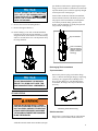
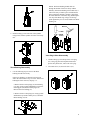
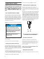
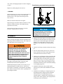
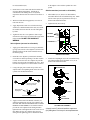
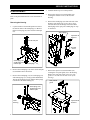
SERVICE INSTRUCTIONS
4. Stand the breaker up in a vertical position.
DISASSEMBLY
Refer to the parts illustration for correct orientation of
parts.
Removing the Housing
1. Lay the breaker in a horizontal position to remove
the tool bit. Remove the sound plug (13). Remove
the hex socket plug (28). Drive out the retainer pin
(27).
5. Remove the capscrews (25) and washers (26)
securing the window covers (21 & 24) to the
housing.
6. Remove the sound plugs (10) from each side of the
housing (some models do not have these plugs).
Unscrew the hoses and fittings and remove them.
Install plugs in the open ports. Install plugs or caps
on the hoses.
sound plugs
capscrews &
washers
tool bit rod pins
window
covers
sound plug, hex
socket plug and
retainer pin
sound plugs
2. Remove the sound plugs (12). Drive out the rod pins
(43) and then remove the tool bit.
3. Remove the sound plugs (13), hex socket plugs (35)
and retaining rings (31). Using a punch and hammer,
Tap out the retaining pins (29) and the rubber plugs
(30). Remove the lower bushing (37).
7. Remove the capscrews (28) and washers (29)
securing the wear plate guide (30) to the housing.
Remove the wear plate guide (some wear plate
guides are located near the mid section of the
housing).
wear plate &
guide
sound plugs, hex
socket plugs and
retainer pins
lower
bushing
2
capscrews &
washers
SB SERIES
SOOSAN HYDRAULIC BREAKER
SERVICE MANUAL
SOOSAN
DO NOT ATTEMPT TO LIFT THE POWER
CELL OUT OF THE HOUSING WITH FITTINGS INSTALLED IN THE IN AND OUT
PORTS. THE FITTINGS WILL INTERFERE
WITH THE HOUSING.
8. Remove the excavator mounting bracket.
gas chamber) which assists in producing the impact
energy. This accumulator or chamber is located in the
top of the breaker power cell and is typically charged
with 230 psi/16 bar of nitrogen gas.
Some breaker models also contain an accumulator
located at the mid-section of the breaker power cell.
The purpose of this accumulator is to dampen the
recoil shock produced during operation of the
breaker. This accumulator is typically charged with
785 psi/54 bar of nitrogen gas.
9. Remove the upper cushion (1).
10. Install a lifting eye into each of the threaded holes
located in the top of the main accumulator (1). Using
slings and a hoist, lift the breaker out of the housing
and set it on a flat surface in a vertical position. Keep
the slings attached.
top accumulator
side accumulator
(can be serviced
without removing
power cell from
housing)
Discharging The Accumulators
Top Accumulator
DO NOT DISASSEMBLE THE BREAKER
WHILE IT IS LAYING ON ITS SIDE. THIS
MAY DAMAGE INTERNAL COMPONENTS.
Remove the protective plug (79) from the charge
valve (3). Release the nitrogen charge by depressing
the charge valve poppet with a #2 Phillips screwdriver or other blunt tool. After discharging the
accumulator, the charge valve may be removed if
necessary.
Accumulators
SERIOUS INJURY MAY RESULT FROM A
PART OR OIL MOVING AT HIGH VELOCITY
DUE TO SUDDEN, UNEXPECTED RELEASE
OF GAS UNDER PRESSURE. DISCHARGE
THE ACCUMULATOR BEFORE DISASSEMBLING THE BREAKER.
Removing the Protective Plug
Side Accumulator
Remove the 2 o-ring plugs (56 & 58). Then turn the
charge valve (54) 1 to 2 turns counter clockwise.
All breaker models contain an accumulator (nitrogen
3
capscrew
cover
diaphragm
discharging the side accumulator
Side Accumulator Disassembly
NOTE: The side accumulator can be serviced
without removing the power cell from the
housing.
If the accumulator does not require servicing, than there
is no need to disassemble it. However, if the breaker is
being disassembled for servicing, it is a good idea to also
dissassemble and inspect the accumulator and replace
the diaphragm and seals. The weight of the assembled
breaker will help provide leverage for loosening the
capscrews.
1. First loosen the capscrews (52) that secure the cover
to the body of the accumulator. Do not remove the
capscrews at this time. NOTE: These capscrews may
be loosened and removed after the accumulator has
been removed from the breaker power cell.
body
o-ring &
backup ring
Accumulator, Piston, & Main Accumulator
Disassembly
1. Unscrew and remove the 4 nuts (39). Do not use an
impact wrench. Remove the 4 washers (41).
nut
washer
tie rod
2. Unscrew and remove the 4 tie rods (40). Do not use
an impact wrench. Keep the tie rods and tie rod nuts
(42) together in matched sets. Lift off the main
accumulator using lifting eyes, slings, and a hoist.
2. Remove the side accumulator from the breaker power
cell as an assembly by removing 4 capscrews (49).
3. Remove all capscrews and lift off the cover (51).
accumulator
assembly
cylinder
4. Lift out the diaphragm (50).
5. Discard the o-ring and backup ring (46 & 47).
3. Install a lifting eye into the top of the piston (16).
Using a hoist, lift the piston and seal retainer (5) out
of the cylinder (6). Remove the seal retainer off of
the piston by tapping it with a rubber hammer.
Remove and discard the o-rings.
4
NOTE: The thrust bushing should slide out
through the bottom of the lower body without
difficulty. If the thrust bushing will not slide out, it
will be necessary to obtain a piece of aluminum or
brass round stock that has a diameter larger than
the inside diameter of the thrust ring and then place
it on top of the thrust ring. Using a rod or large
punch against the piece of stock, hammer the thrust
bushing out.
MALLET
ROD
5. Install a lifting eye into each side of the cylinder.
Using a hoist, lift the cylinder off of the lower body
(26).
ROUND
STOCK
Valve Plug & Valve Disassembly
1.
Thrust Bushing Disassembly
Install a lifting eye into the top of the valve plug
(18). Using a pry bar and scrap metal material to
protect the cylinder face, remove the valve plug.
2. Lift out the valve (17) and valve sleeve (67).
1. Use the following steps to remove the thrust
bushing from the lower body.
If the lower bushing (37) has not been removed,
follow the instructions in step "a" below. If the lower
bushing has been removed, skip step "a".
a. Remove the hex socket plugs (35) and retaining
(31) rings. Using a punch and hammer, Tap out the
retaining pins (29) and the rubber plugs (30).
Remove the lower bushing (37).
b. Remove the hex socket plug (28). Using a punch
and hammer, tap out the retainer pin (27). Slide the
thrust bushing (36) out.
5
INSPECTION OF PARTS
If cracks are present, the part must be replaced.
• THRUST BUSHING & LOWER BUSHING
NOTE: In addition to the instructions and
guidelines below, also see the pages
titled "WEAR TOLERANCES" at the end
of the "SERVICE INSTRUCTIONS" section.
• SEAL CARRIER, PISTON AND CYLINDER
Inspect the surfaces of the bore of the seal carrier and
cylinder and the surface of the piston for wear, galling,
and cracks. A light scuffing or burnishing of surfaces is
normal. Check especially for freedom of movement of the
parts and that the piston does not stick or bind as it is
moved in the seal carrier and cylinder. Coat the parts
with hydraulic oil for this test.
Inspect the thrust bushing and lower bushing for
excessive galling and metal pickup on the tool bit. Also
check for cracks. If cracks are present, the parts must be
replaced.
The extent of wear of the upper and lower bushings and
the tool bit can be checked by moving the tool bit back
and forth and measuring the gap between the tool bit
and the lower bushing. If the gap is more than 0.354 in./9
mm the upper bushing, lower bushing, and the tool bit
should be replaced. A gap in excess of 0.354 in./9 mm will
cause damage to the piston. Do not just replace the tool
bit or the lower bushing individually as this will result in
premature wear of the replaced component. It is recommended to replace all worn components.
If small burrs are found, remove them with 220 grit emery
cloth.
The parts in the breaker are finely
manufactured with critical tolerances.
REFURBISHING OF PARTS SHOULD ONLY
BE ACCOMPLISHED BY AN ADEQUATELY
EQUIPPED MACHINE SHOP.
PARTS SHOULD NEVER BE POLISHED OR
BUFFED WITHOUT THE USE OF A
TURNING LATHE.
MOVE THE TOOL BIT BACK & FORTH & MEASURE THE
GAP BETWEEN TOOL BIT & LOWER BUSHING
• TIE RODS & TIE ROD NUTS
If galling is present, consult the dealer to see if the part
may be reworked.
If cracks are present, the part must be replaced.
• VALVE SLEEVE, VALVE & VALVE PLUG
Inspect the surface of the bore of the valve sleeve and
the surface of the valve and valve plug for wear, galling,
and cracks. A light scuffing or burnishing of surfaces is
normal. Check especially for freedom of movement of the
valve in the valve sleeve.
Inspect the tie rods and nuts for wear and cracks.
When clean and coated with anti-sieze, the tie rods
should thread into the nuts without any effort. If some
resistance is encountered, check all threads for dirt
particles or damage.
NOTE: If a tie rod is found to be broken, all 4
tie rods must be replaced.
• RETAINING PINS & ROD PINS
If small burrs are found, remove them with 220 grit emery
cloth. Do not break the sharp edges of the valve sleeve
or valve spool as this will cause the valve to malfunction.
If galling is present, the part should be replaced.
6
Inspect all retaining pins and tool retainers for excessive
wear, cracks, and chipping. Replace if cracks or chipping
is noted.
Thrust Bushing, and Lower Bushing Assembly
Replace any rubber plug that was removed.
• HOUSING
Inspect the housing for cracks on the outside and on the
inside. If cracks are present, have a certified welder
perform repairs. After repairs, the housing must be
stress relieved.
Make sure all decals and stickers are legible.
Inspect the upper and down cushions for distress. If the
material is crushed, cracked, or has chunks missing,
replacement is necessary.
Installing The Thrust Bushing
Inspect the all wear plates for excessive wear and
looseness. Replace parts as necessary.
ASSEMBLY
Before assembly, thoroughly clean all components with a
degreasing solution and then blow dry with compressed
air to thoroughly clean oil passage ways.
Exercise care when using compressed air
and degreasing solutions. Always use
protective eye wear and breathing
protection. If flammable solvents are
used, make sure they are used in an area
where there will be no presence of open
flame, static electricity or sparks from
electrical equipment such as electric
motors.
When assembling internal metal parts, always coat them
thoroughly with hydraulic fluid. Seals and o-rings
should be lubricated with clean hydraulic oil.
Handle machined parts carefully to ensure they are not
damaged during the assembly process. Do not force
parts together. If difficulty is encountered in assembling
parts, inspect each part for burrs, nicks, or galling before
proceeding any further.
The thrust bushing is custom fitted to
each individual breaker. A new thrust
busing must be machined prior to
installation into the lower body.
1. Measure the outside diameter of the thrust bushing
(36) that was removed from the lower body (26) in at
least two places. Record the highest measurement.
Machine the outside diameter of the new thrust
bushing to .001 inch under the recorded measurement.
2. Turn the lower body so that the tool bit end is facing
up.
3. Place the thrust bushing into the bore of the lower
body so that the bevel on the inside diameter faces
toward the tool bit end of the lower body.
4. Obtain a piece of aluminum or brass round stock that
has a diameter larger than the inside diameter of the
thrust bushing. Place the round stock on top of the
upper bushing. Using a rod or large punch against
the piece of stock, tap the thrust bushing into place.
Periodically check the position of the thrust bushing
as the tapping progresses.
5. Install the retainer pin. Using a punch, tap the
retainer pin (27) until it seats. Install the hex socket
plug (26).
6. Install the lower bushing (37). Align the grooves in
the bushing with the retainer pin holes. Install the
retainer pins (29), new rubber plugs (30), and
retaining rings (31). Install the hex socket plugs (35)
using Loctite™ #608. Tighten to the torque specified
in the torque chart in this manual.
7
7. Position the lower body so that the lower bushing is
resting on the floor or work surface.
Seal Carrier Assembly and Installation
Cylinder Assembly
1. Apply clean hydraulic fluid and install an o-ring (4)
into the top outside groove of the seal carrier (5) as
shown in the illustration on this page.
1. Apply clean hydraulic fluid and install the seals (12,
13 & 14) to the underside of the cylinder (6) as
shown in the illustration below.
2. Apply clean hydraulic fluid and install the seals (9,
10 & 11) as shown in the illustration on this page.
MAIN ACCUMULATOR
Item 10
CYLINDER
CYLINDER
PISTON
PISTON
LOWER BODY
SEAL CARRIER
14
13
Item 9
Item 4
12
Item 11
Seal Carrier Seals
Cylinder Seals
2. Position the cylinder on top of the lower body as
shown in the parts illustration.
Valve and Valve Seals Installation
3. Apply grease and install an o-ring (4) into the
groove located at the bottom, outside of the seal
carrier as shown in the illustration above.
4. Place the seal carrier onto the piston. Make sure the
seal carrier is positioned as shown in the parts
illustration. Slide the seal carrier down the piston and
into the cylinder.
Do not hammer the spool or sleeve into
the bore in the main body.
Main Accumulator Assembly
Hammering the spool or sleeve into the
bore will damage the spool stem.
1. Apply grease and install an o-ring (4) into the
groove on the main accumulator (1) as shown in the
illustration below.
1. Lubricate the valve sleeve (67) with hydraulic fluid
and then install it into the cylinder.
2. Lubricate the valve (17) with hydraulic fluid and then
install the valve into the valve sleeve as shown in
the parts illustration.
MAIN ACCUMULATOR
PISTON
CYLINDER
3. Apply clean hydraulic fluid and install the o-rings
(19 & 20) onto the valve plug (18). Install the valve
plug.
item 4
SEAL CARRIER
Piston Installation
1. First make sure the interior of the cylinder is coated
with hydraulic fluid.
2. Coat the piston (38) with hydraulic fluid.
3. Install a lifting eye into the top of the piston. Using a
hoist, insert the piston into the cylinder. Lower the
piston slowly, being carefull not to damage it or the
interior of the cylinder.
8
Install O-ring Into Grove on Main Accumulator
2. Install lifting eyes into the top of the main accumulator. Using a hoist, set the main accumulator on top of
the cylinder as shown in the exploded parts illustration.
Tie Rod Assembly
1. Apply Kopr-Kote™ anti-sieze to the threads of each
tie rod (40) and nut (42).
on the adjuster valve and the cylinder face correspond.
2. Install one tie rod at a time and check it and the nut
for proper thread engagement. If difficulty is
encountered while turning the tie rod by hand,
inspect the threads of the tie rod and nut for burrs or
dirt.
4. With successful thread engagement, screw the tie
rods into the nuts.
Side Accumulator (not used on all models)
1. If the holders (61, 62, & 63) were disassembled,
reassemble them to the accumulator body (48). Make
sure the center pin (64) is positioned correctly as
shown in the illustration below.
2. Tighten the nut (60) securely.
5. Apply Kopr-Kote™ anti-sieze to both sides of the
washers (41) and the threads of the nuts (39). Install
the washers and nuts onto the tie rods and tighten
by hand.
6. Tighten the nuts in a cross pattern in three torque
increments to the torque specified in the torque chart
in this manual. DO NOT USE AN IMPACT
WRENCH.
HOLDERS
NUT
CENTER PIN
HOLDER PIN
Valve Adjuster (not used on all models)
1. Apply grease and install a new o-ring (73) and backup rings (68) onto the valve adjuster as shown in the
illustration below. NOTE: Some models do not use
the back-up rings.
CENTER PIN & HOLDERS
2. Install the valve adjuster by hand until it bottoms
out in the bore and stops turning. If an allen wrench
is used, do not force the valve adjuster beyond the
bottom-out point as this will damage the valve. Then
turn the valve adjuster 2-1/2 turns counter clockwise.
3. Using a felt pen, place a mark on top of the valve
adjuster and a corresponding mark on the face of the
cylinder. See the illustration below.
3. Install a new diaphragm (50) to the accumulator body
(48) and then install the accumulator cover (51) as
shown in the illustration below.
CAPSCREW (52)
COVER
DIAPHRAGM
Location of o-ring (and
back-up rings if used)
Mark position after
adjusting valve
BODY
Top view of valve adjuster and nut
O-RING
BACKUP RING
4. Apply Loctite™ 680 to the threads of the nut (77)
and then install the nut onto the valve adjuster. DO
NOT LET THE VALVE ADJUSTER TURN - IT MUST
REMAIN AT THE MARKS. Use an allen wrench to
prevent the valve adjuster from turning and then
tighten the nut. Final tighten the nut to 100 ft. lb./136
Nm. Make sure the valve adjuster does not turn
during the nut tightening process and that the mark
ACCUMULATOR ASSEMBLY
4. Apply Loctite™ 242 and install the capscrews
(52) and tighten. Final torque is accomplished later.
9
Accumulator Charging
Charge each accumulator as specified on the page titled
"NITROGEN CHARGING THE ACCUMULATOR" found
earlier in this manual.
Housing Installation
NOTE: If maintenance is performed on a
breaker to the extent that the power cell is
removed from the housing, it is always recommended to take advantage of this opportunity
to replace the upper and down cushions and
wear plates even if they appear only slightly
used.
1. Install a lifting eye into each of the threaded holes in
the top of the main accumulator assembly. Attach
slings and a hoist.
2. Lift the power cell and lower it into the housing.
Make sure the oil ports are positioned with the
window opening in the housing. Lower the power
cell into the housing until it rests against the down
cushion (16).
Lowering The Power Cell Into The Housing
3. Install the wear plate guide (30) with a new wear
plate (2). Secure in place with capscrews (28) and
washers (29).
4. Install the upper cushion (1).
5. Install the mounting bracket.
Tool Bit Installation
1. Grease the top 250 mm/10 inches of the tool bit with
high temperature grease and insert the tool bit into
the lower body. Align the notches of the bit with the
rod pin holes in the lower body and then install the
rod pins.
2. Install the stop pin (43) followed by the hex socket
10
plug (28) .