1
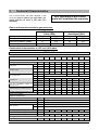
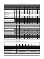
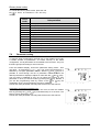
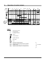
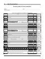
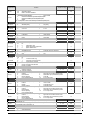
G Series
USER’S MANUAL
FOR MODULATING BOILER WITH GAS BURNER
EQUIPPED FOR NATURAL GAS
Type : B23
Category I2H
Equipment complying with European Community Directives:
- Low voltage (73/23/CEE)
- Electromagnetic compatibility (89/336/CEE)
- Efficiency (92/42/CEE)
- as appliancez (90/396/CEE)
ADDRESS: ATLANTIC BOILERS, PO BOX 11, ASHTON UNDER LYNE, OL6 7TR
WEB: WWW.ATLANTICBOILERS.COM EMAIL: [email protected]
TEL: 0161 621 5960 FAX: 0161 621 5966
CONTENTS
CONTENTS ____________________________________________________________3
1
Technical characteristics. _____________________________________________4
2
Installation. _________________________________________________________6
3
Start-up. ____________________________________________________________6
4
Shut-down. _________________________________________________________6
5
Maintenance. ________________________________________________________6
6
Frost protection. _____________________________________________________6
7
User interface and boiler management. __________________________________7
7.1
7.2
7.3
7.4
7.5
7.6
Presentation of the interface ______________________________________________7
LCD display ____________________________________________________________7
Operating modes ________________________________________________________8
Set-point adjustment ____________________________________________________10
Information on boiler status ______________________________________________11
Parameter setting_______________________________________________________14
8
Operation of control cabinet.__________________________________________15
9
List of parameters. __________________________________________________16
00GHA9087-#
User’s Manual for OPTIMAGAZ and CONDENSAGAZ G SERIES
Page 3 / 18
1
Technical Characteristics.
Any interference with sealed
parts will invalidate the warranty
This G Series boiler has been adjusted in the
works for group H natural gas (type G20), gas
supply pressure 20 mbar or 300 mbar (see
data plate).
Rated, minimum and maximum gas pressures.
Type H gas
(Lacq) (G20)
20 mbar
300 mbar
20
300
17
270
25
330
Model
Rated pressure (mbar)
Minimum pressure (mbar)
Maximum pressure (mbar)
Type L gas
(Groningue) (G25)
25 mbar
300 mbar
25
300
20
270
30
330
Combustion characteristics at 15°C and 1013 mbar.
OPTIMAGAZ
Model – G Series
Unit
G116
G145
G174
G232
G291
G348
G407
G465
kW
114
144
173
230
288
345
403
423
kW
121,3
151,5
185.0
248.0
306.0
368.0
435,0
455,0
Combustion at 15°C and 1013 mbar
Rated pressure P
Max
Heat output
Gas flow (G20)
CO2 content (G20)
Flue gas flow
Flue gas temperature
operating mode
(60/80
°C
Intake air flow at 1013 mbar and 15°C
Min
kW
30,0
37,5
47.0
61.5
77.0
93.0
109,0
112,0
Max
m3/h
12,8
16,0
19.6
26.2
32.4
38.9
46,0
48,1
Min
3
m /h
3,2
4,0
5.0
6.5
8.2
9.8
11,5
11,9
Max
%
8.5 – 8.7
8.7 – 8.9
8,9 – 9,0
Min
%
Max
g/s
57
71
87
118
8.0 – 8.2
142
171
199
208
Min
g/s
15
19
24
31
39
47
55
56
Max
°C
134
136
138
139
138
146
145
142
Min
°C
63
64
65
67
66
67
69
72
Max
m3/h
160,4
200,3
244.6
331.4
400.3
481.4
557,4
583,1
Min
m3/h
42,4
53,0
67.1
86.8
108.7
131.3
153,9
158,2
mg/kWh
35
45
50
45
55
55
50
50
315
342
371
Average weighted annual emission of
NOx accoring to EN656
Hydraulic characteristics
Safe temperature limit
°C
106
Outlet water temperature adjustment range
°C
65 – 90
Minimum return water temperature
°C
45
Max
bar
4
Min
bar
Water pressure
1 (cold)
Water capacity
L
116
144
153
256
Rated water flow rate through boiler
3
285
m /h
Hydraulic pressure loss in boiler at P/20
mCE
1,22
1,43
1.0
1.27
1.17
0.71
0,87
1,17
kg
370
405
440
550
600
660
725
780
P/20 (max = P/15)
Sundry
Weight empty
00GHA9087-#
User’s Manual for OPTIMAGAZ and CONDENSAGAZ G SERIES
Page 4 / 18
CONDENSAGAZ
Model – G Series…
Unité
G116
G145
G174
G232
G291
G348
G407
G465
kW
116
145
174
232
290
348
407
443
Maxi
kW
119,7
148,7
181.0
241.0
297.0
359.0
423,5
462,0
Mini
kW
30,0
37,0
45.0
60.0
74.5
90.0
106,0
115,0
Maxi
3
m /h
12,7
15,7
19.2
25.5
31.4
38.0
44,8
48,9
Mini
m3/h
3,2
3,9
4.8
6.4
7.9
9.5
11,2
12,2
Maxi
%
Mini
%
Maxi
g/s
56
70
85
114
138
167
194
202
Mini
g/s
15
19
23
30
36
45
53
58
Maxi
°C
75
78
77
75
76
79
78
Mini
°C
57
59
58
59
56
59
60
Maxi
3
m /h
158,2
196,6
239.3
322.0
388.5
469.6
542,7
592,0
Mini
m3/h
42,4
52,2
64.3
85.7
105.2
127.1
149,7
162,4
45
45
50
55
55
55
359
391
424
Combustion at 15°C and 1013 mbar
Rated pressure P
Heat output
Gas flow (G20)
CO2 content (G20)
Flue gas flow
Flue gas temperature
operating mode
(60/80
°C
Intake air flow at 1013 mbar and 15°C
Average weighted annual emission of
NOx accoring to EN656
8.5 – 8.7
8.7 – 8.9
8,9 – 9,0
8.0 – 8.2
40
mg/kWh
Hydraulic characteristics
Safe temperature limit
°C
106
Outlet water temperature adjustment range
°C
65 – 90
Minimum return water temperature
Water pressure
°C
45
Maxi
bar
4
Mini
bar
1
Water capacity
L
Rated water flow rate through boiler
3
m /h
P/20 (Max: P/15)
Maxi
m3/h
P/15
Mini
3
P/45
Rated water flow rate through
condensation heat exchanger
140
175
185
296
m /h
328
Hydraulic pressure loss in boiler at P/20
mCE
1,22
1,4
1.0
1.27
1.17
0.71
0,87
1,17
Hydraulic pressure loss in condensation heat
exchanger at P/20
mCE
0,22
0,18
0.25
0.15
0.22
0.25
0,31
0,38
kg
425
450
485
600
650
725
805
880
Sundry
Weight empty
Characteristics of electrical connections.
OPTIMAGAZ - CONDENSAGAZ
Model –G Series…
Electric power consumption (boiler
without accessories) (W)
Electric power supply (V)
Rated current without accessories (A)
Peak current without accessories (A)
Main fuse rating
(excluding GUILLOT items) (A)
Max length of probe cables
Power terminal outputs
00GHA9087-#
G116
G145
G174
G232
G291
G348
G407
G465
180
250
260
270
390
360
550
620
1,3
1,2
230 V AC +10 % -15 % 50 Hz
1.15
1.2
1.7
1.6
2.5
2,8
3,0
3,0
12,5
DHW probes: 10 m
Ambient thermostat: 30 m
External probe: 30 m
Ambient probe: 30 m
230 V AC +10 % -15 %
5 mA to 2 A
User’s Manual for OPTIMAGAZ and CONDENSAGAZ G SERIES
Page 5 / 18
2
Installation.
The equipment must be installed and maintained
by a qualified professional according to all current
regulations and best professional practices
applicable in the country where the boiler is
installed.
3
The boiler must be installed in premises provided
with ventilation openings in compliance with
applicable regulations (see installation and
maintenance manual).
Start-up.
Before shipping, all boilers undergo a works test
with group H natural gas (type G20) during which
all necessary adjustments are made. First start-up
must be carried out by our
Service Centre 0161 621 5960
For temporary start-up, proceed as follows:
1. Switch on the power (main on/off switch)
2. Create a heat demand in comfort mode by way
of the client interface (see “Interface
presentation” section)
3. After the burner has started up, check for leaks
in the gas line using a foam-producing product.
Check that combustion is safe and complete.
4. Adjust the clock. (See summary table of client
parameters at the end of the manual).
4
Any interference with sealed
parts will invalidate the warranty.
Shut-down.
To shut down the boiler, proceed as follows:
1. Switch off the main ON/OFF switch.
2. In the event of a prolonged shut-down close
the isolating valve of the gas supply.
5
Maintenance.
Boiler maintenance must be carried out once a
year (see Installation and Maintenance Manual).
Call on the services of a qualified professional for
all maintenance operations (see Installation
Manual).
6
Frost protection.
The guarantee remains valid only if the heating
network is treated with anti-freeze when there is a
risk of frost.
If it is decided nevertheless to drain the system,
the user is responsible for ensuring that no water
remains in the boiler.
• Close the gas supply isolating valve.
• Close the outlet and return stop-cocks.
• Open the safety valve to create an air inlet on
the upper part of the boiler tubes; open the
cock of the boiler drain tube.
• Switch off the main ON/OFF switch.
00GHA9087-#
User’s Manual for OPTIMAGAZ and CONDENSAGAZ G SERIES
Page 6 / 18
7
User interface and boiler management.
7.1
Presentation of the interface
The boiler’s client interface comprises an on/off
switch, a drawer-type fuse-holder, an
electronic board with a backlit LCD screen (2
lines of 4 figures + pictograms) and 10 keys,
and an opening for insertion of 2 96 x 96
regulators or 1 144 x 96 regulator.
All client settings and possible parameter
adjustments are performed through this
interface. It also allows the operator to consult
information concerning boiler operation.
Mode selection
keys
Programming
keys
Set-point
adjustment
buttons
Information key
Re-set button
Openings for
installation of
regulators
Boiler
power
on-off switch
Boiler fuse-holder
7.2
LCD display
The standard display presents the state of the
boiler (operating mode, time, time programming,
boiler temperature, flame presence, possible
faults).
DHW mode
Heating mode
Pictograms :
DHW preparation
under way or DHW t°
display
Heating activated or
display of boiler or
environment set-point
Comfort mode
Reduced-power
mode
Outdoor t° display
Flame presence
Alarm
00GHA9087-#
Time
Boiler
temperature
Summary of time programming:
Each square represents a period of heating in comfort mode
(by 1-hour time intervals). The flashing square indicates the
current hour.
User’s Manual for OPTIMAGAZ and CONDENSAGAZ G SERIES
Page 7 / 18
If a non-blocking fault occurs, the time display alternates with display of
the fault code.
This type of defect does not lead to a shut-down.
When a fault leads to boiler shut-down, a flashing display of the fault code
replaces the boiler temperature display. An alarm bell is displayed in the
bottom left corner of the display window.
Refer to the “Error message” section for information on the fault codes.
makes it possible
In both cases a brief pressure on the Information key
to display only the fault code. Press keys
and
simultaneously for
display of the extended fault code (Press
, then
or
to return to
standard display).
7.3
Operating modes
Heating mode key
For selection of heating mode among the Stop, Auto, Comfort and Eco modes
Stop
No heating demand has been received. The frost
protection function is activated.
Comfort
Permanent comfort mode.
Burner power is adjusted to maintain the heating setpoint .
Eco
Permanent reduced-power mode.
Burner power is adjusted to maintain the reduced heating
set-point. (Parameter n° 5, see paragraph 7.6).
00GHA9087-#
User’s Manual for OPTIMAGAZ and CONDENSAGAZ G SERIES
Page 8 / 18
Auto
The regulator alternates Comfort and Eco modes,
according to the time programming.
Two further “service” modes are available. They
make it possible to carry out measurements on
the boiler.
Flue
cleaning
This mode allows the burner to operate at full load.
and
simultaneously for approximately 3
Press
seconds
The burner starts up (if it was not already in operation)
and power increases to provide maximum heat output.
The burner shuts down when the temperature limiting
themostat is triggered (88°C). This is a safety fea ture
independent of the maximum operating temperature
which cannot exceed 85°C.
1
While this function is activated, a forcing signal is
generated to evacuate heat.
Regulator
off
This mode allows burner heat output to be fixed
manually
Press
and
simultaneously for approximately 6
seconds when in a standard mode or for 3 seconds when
in the flue cleaning mode.
2
The relative power set-point of the burner is displayed
on the screen.
The
and
keys can be used to adjust the set-point
and
can be used to go
value by 1 % steps. Keys
directly to the min. or max. power set-point (0 % or
100 %)
To exit one of these two modes and return to standard
operation, press
and
simultaneously for 1 second.
1
Forcing signal: triggers pump start-up and/or opening of the 3-way valve of the connected heating circuits
so as to evacuate heat. This signal is triggered by:
- Electronic temperature limiter.
- Safety thermostat.
- Flue cleaning mode
- Regulator off mode.
- Boiler frost protection.
2
Relative power: this is the actual power output of the burner with respect to its modulation range.
0 % corresponds to minimum power and 100 % to maximum power of the boiler.
To convert this to a percentage of heat output (or load factor), the following formula can be used:
%Qcal =
Powerrelative ⋅ (100 − %Qmin )
+ %Qmin = 0.75 ⋅ Prel + 25
100
Displayed percentage
Load factor (%)
00GHA9087-#
100
100
90
92.5
80
85
70
77.5
60
70
50
62.5
40
55
30
47.5
User’s Manual for OPTIMAGAZ and CONDENSAGAZ G SERIES
20
40
10
32.5
0
25
Page 9 / 18
DHW Mode key
Activates / disactivates the production of domestic hot water
DHW production activated
7.4
DHW production disactivated
Set-point adjustment
Adjustment of the heating set-point
According to the mode of regulation chosen, the set-point
temperature can have different meanings:
In constant temperature mode, the set point is a boiler outlet
water temperature.
In regulated mode, depending on outside temperature or
ambient temperature, or both, the set point is an ambient
temperature.
Press the heating set-point key
. The current set-point is
displayed.
or
key to adjust the heating set point temperature.
Use the
To exit the set point adjustment screen press the heating mode ,
DHW mode , or heating set point
key.
If no key is pressed the interface returns to the standard display after
about 8 minutes.
Adjustment of DHW set point
This function is available only if DHW production is connected to the
boiler.
Press the domestic hot water set point key . The current value of
the set point is displayed.
Use the
or
key to adjust the DHW set point temperature.
To exit the set point adjustment screen press the heating mode ,
key.
DHW mode , or DHW set point
If no key is pressed the interface returns to the standard display after
about 8 minutes.
00GHA9087-#
User’s Manual for OPTIMAGAZ and CONDENSAGAZ G SERIES
Page 10 / 18
7.5
Information on boiler status
Info key
At any moment basic information on the boiler can
be obtained by pressing the Info key
. Each
1
DHW temperature
2
Not used
3
Burner operation phase code
(see section on “Burner phase codes”)
4
Outside temperature
5
Albatros error code
(see section on “Error messages”)
6
Boiler temperature
pressure on
variable.
moves the display to the following
3
To return to standard display, press the
3
or
key.
Albatros: name given by SIEMENS to the fault codes.
00GHA9087-#
User’s Manual for OPTIMAGAZ and CONDENSAGAZ G SERIES
Page 11 / 18
Table of additional information
From the Info mode (one pressure on the Info key ), it is possible
to obtain additional data concerning boiler operation. For this, press
and
simultaneously for about 3 seconds. The time display is
replaced by an address composed of a letter (b, C, d) and a figure
(from 0 to 7). Use keys
and
to modify the letter. Use keys
or
to modify the figure.
to return to Info mode or
or
to return to the
Press key
default display.
Address
Information
b0
b1
b2
b3
b4
b5
b6
b7
Extended fault code
Return probe temperature
Flue gas temperature
External temperature probe
Composite outside temperature
Attenuated outside temperature
3-way valve kit oulet temperature probe
C1
C2
C3
C4
C5
C6
Ionisation current (µA)
Measured fan speed
Measured fan PWM Signal
2
Relative power (see page 9)
Actual difference set point / measured value
d1
d2
d3
d4
d5
d6
Set point for boiler temperature (including DHW and other heating circuits)
Heating temperature set point
Ambient temperature set point
DHW temperature set point
Level of modulation of max. fan speed in heating mode
Max. speed in heating mode
00GHA9087-#
User’s Manual for OPTIMAGAZ and CONDENSAGAZ G SERIES
Page 12 / 18
Error messages
In the event of a fault leading to shut-down, the
alarm signal is permanently displayed and the
fault code flashes. To reset the system, correct
the fault and then press the reset button
for at
least 2 seconds.
00GHA9087-#
Albatros
number
Interpretation
0
10
20
28
32
40
50
61
62
81
82
91
92
100
105
110
111
113
128
129
130
132
133
140
148
151
152
153
154
160
161
162
164
166
180
181
183
No input in Albatros code – no defect
External probe fault
Boiler probe fault
Flue gas probe fault
Clip-in probe fault
Return probe fault
DHW probe fault
Ambient temperature regulation: Failure
Ambient temperature regulation: error or radion clock error
Short-circuit on LPB bus or bus power supply failure
Address collision on LPB bus (several identical addresses)
Data loss in EEPROM
Equipment fault in electronic part
Two master clocks in system
Maintenance alert
Safety thermostat triggered (electronic or mechanical)
Triggering of limiting thermostat
Excess over authorized flue gas temperature
Flame failure during operation
Poor air supply
Power limitation due to excessive flue gas temperature
Response of gas pressure switch
No flame formation after expiry of safety period
Segment number or LPB equipment number inadmissible
LPB and LMU communication interfaces not compatible
Internal LMU fault
LMU parameter error
Eqipment in locked position
Inconsistency in Flow or Return or Ambient or ECS temperatures
Fan threshold speed not reached
Maximum fan speed exceeded
Air pressure switch not closed
Response of flow controller / low water level contact
Air pressure switch not open
Flue cleaning function activated
Regulator off function activated
Equipment in parameter setting mode
User’s Manual for OPTIMAGAZ and CONDENSAGAZ G SERIES
Page 13 / 18
Burner phase codes
To consult the burner phase codes, press the Info
key
3 times, as indicated in the “Info key”
section
Phase
code
0
1
2
3
4
5
6
10
11
12
20
22
99
7.6
Interpretation
Stand-by (no heat demand)
Start-up blocked
Fan ramping up to speed
Preventilation
Waiting time
Pre-ignition time
Safety period
Heating mode
DHW mode
Parallel heating and DHW operation
Post-ventilation
Return to initial position
Failure position (display of current fault code)
Parameter setting
To optimize boiler configuration, the final user or the installer can modify
a certain number of parameters. To ensure security of the boiler
configuration, not all parameters are accessible to the final user. They are
therefore grouped according to level of access.
From the standard display, access the parameter setting mode – final
user level – by pressing the
or
key. The screen then displays a P
and
keys it is
followed by a 3-figure parameter number. With the
possible to scroll through the list of parameter numbers. When the
and
keys.
desired parameter is displayed, adjust its value with the
The new value is validated as soon as you select the previous or next
parameter or when you exit the mode by pressing the
key. Beware, if
you exit the programming mode by means of the
or
key the
modification of the current parameter will not be validated.
Consult the client parameter summary table at the end of this manual.
Parameters accessible at installer level
From the parameter setting mode, final user level, access the installer
level by pressing the
and
keys simultaneously for 3 seconds. The
letter P is then replaced by an H.
Consult the client parameter summary table at the end of this manual.
00GHA9087-#
User’s Manual for OPTIMAGAZ and CONDENSAGAZ G SERIES
Page 14 / 18
8
Operation of control cabinet.
Phase
Code
PG, CD,
TL
0
Stand-by
2
3
Montée
Pre-.
en régime ventilation
4
Waiting
5
Preheating
6
Safety
period
10, 11, 12
Operation
20
22
Post Ret urn to
ventilation
zero
1
Blockage of
Start -up
99
Safety
Shut-down
Nmax
N_VL
N_ZL
N_TL
Nzéro
0
5 s.
0 s.
4.2 s.1.8 s.
10 s.
t
Legend:
PG
CD
TL
= Gas pressure switch
= Flow controller
= Limiting thermostat
= Alarm
= Flame detection
= Ignition electrode
= Gas valve
= Fan
Nmax
N_VL
N_ZL
N_TL
Nzero
00GHA9087-#
= Maximum speed authorized
= Maximum speed authorized during modulation.
= Ignition speed
= Minimum speed authorized during modulation.
= Speed less than 200 rpm so considered as nil
User’s Manual for OPTIMAGAZ and CONDENSAGAZ G SERIES
Fan speed
Page 15 / 18
9
List of parameters
Summary table of client parameters
Boiler:
......................................
Serial number: .................................
site : ...........................................................
...........................................................
Please note all modifications to parameters in this document
Function
Adjustment line
Adjustment range
P1
Clock adjustment
Time (current)
P2
Day (current)
P5
Low outlet set point / Low ambient set point (according to mode)
P 10
P
P
P
P
P
P
P
11
12
13
14
15
16
20 à 26
P 30
P
P
P
P
P
P
31
32
33
34
35
36
P 45
H 90
H 91
H 93 à 94
H 505
H 510
P 532
H 534
Time programming of direct heating circuit
Preselection of day(s) to be programmed:
1-7
Complete week
1…7
Day od the week
Start 1st period
End 1st period
Start 2nd period
End 2nd period
Start 3rd period
End 3rd period
Not used
H 542
H 543
H 544
H 545
1-5
6-7
20…80 / 10…26 °C
40 / 15
G291
OPTI CON.
6200 6200
---
1-7
06:00
22:00
--:---:---:---:--
1-7
Monday
to
Friday
Saturday and Sunday
0:00… 24:00
0:00… 24:00
0:00… 24:00
0:00… 24:00
0:00… 24:00
0:00… 24:00
06:00
22:00
--:---:---:---:--
50…65 °C
65
0
0
0
Settings for heating circuits
Maximum heating set point temperature
Over-rise in the instruction of starting temperature for the head of hot water
medical
Slope of direct circuit heating characteristics
Correction of ambient set point for direct heating circuit
G348
OPTI CON.
6000 5850
Minimum boiler power output
Maximum boiler power output
Time delay to shut-down of pump Q1 or to closure of isolating valve Y1, max. 218
min.
(255 = permanent operation of Q1 or permanent opening of Y1)
Minimum burner pause time
00GHA9087-#
---
Monday
to
Friday
Saturday and Sunday
Return to standard time programming for heating and DHW.
(press – and + keys simultaneously for 3 seconds)
Low set point for DHW temperature
Liberation of DHW production:
0
DHW time programming
1
24h/24
Not used
Default value Client setting
00:00… 23:59
1: Monday- 7:
Sunday
0:00… 24:00
0:00… 24:00
0:00… 24:00
0:00… 24:00
0:00… 24:00
0:00… 24:00
Time programming of domestic hot water (DHW)
(activated depending on configuration)
Preselection of day(s) to be programmed:
1-7
Complete week
1-5
1…7
Day od the week
6-7
Start 1st period
End 1st period
Start 2nd period
End 2nd period
Start 3rd period
End 3rd period
Boiler configuration
H 536
Maximum fan speed in heating mode
G116
G145
G174
G232
OPTI CON. OPTI CON. OPTI CON. OPTI CON.
7050 7000 5850 5850 5950 5750 5500 5400
!
65…90 °C
87.0
0…30 K
15
1 … 40
-31 … 31 K
22
0.0
0 … 9950 rpm
G407
OPTI
CON.
5300
5200
See below
G465
OPTI CON.
5550 5550
0 … 9999 kW
0 … 9999 kW
acc. to model
acc. to model
0 … 255 min
5
0 … 3600 sec
300.0
User’s Manual for OPTIMAGAZ and CONDENSAGAZ G SERIES
Page 16 / 18
Function
Adjustment line
Adjustment range
Installation configuration setting:
66
Stand-alone boiler
80
Boiler in cascade installation
Influence of ambient temperature probe on heating circuit (only with ambient control unit) :
Units: influence on direct ciruit (DC)
Tens: not usedi
0
Direct circuit not influenced by ambient temperature probe
H 553
1
Direct circuit controlled by ambient temperature probe
2
Inactive
ex : 01 corresponds to a direct circuit controlled by the ambient temperature probe
H 555.b0
Not used
Type of DHW priority:
H 555.b1
0
Absolute priority
1
No priority
H 555.b2 à b3 Not used
Frost protection of installation :
H 555.b4
0
out of use
1
In use
H 555.b5 - b7 Not used
H 558.b0
Not used
Type of construction :
H 558.b1
0
Lightweight
1
Heavyweight
Type of DHW control device:
H 558.b2
0
Probe
1
Thermostat
H 558.b3 - b7 Not used
H 552
H 604.b0
H 604.b1
H 604.b2
H 604.b3
H 604.b4
H 604.b5
H 604.b6
H 604.b7
H 605
H 606
H 615
H 618
H 619
H 620
H 622
H 623
P 629
Communication by LPB bus
Synchronisation of local / system clock:
b1
b0
0
0
Independent clock
0
1
System time without adjustment
1
0
System Master Clock
Setting of bus supply:
0
Centralized supply
1
Automatic supply by regulators
Display of bus supply :
0
OFF
1
ON
Not used
Allocation of DHW to consumers:
b6
b5
0
0
Local consumers only,
0
1
Consumers of same segment,
1
0
All consumers of system
Priority of LPB bus over power demand via 0 … 10 V input:
0
priority to external power demand
1
priority to LPB bus
Device address
l
0 … 16
Segment address:
0
generator segment
0 … 14
1 … 14 consumer segments
Function of programmable output K2 of LMU :
0
Inactive
7
Signal for hot air curtain function active
2
External alarm
8
Downstream pump for balancing vessel
3
Burner operating
9
Pump Q8
6
Pump of DHW network
12
0-10 V input active
Input / Output relay-operated Clip-ins (AGU2.51x)
Function of programmable input of clip-in :
0
Inactive
3
Hot air curtain
1
Modem
4
Prescribed set point
2
Modem reverser
5
Prescribed power
Function of the Ist programmable output of clip-in :
0
Inactive
7
Signal for hot air curtain function active
2
External alarm
8
Downstream pump for balancing vessel
3
Burner operating
12
0-10 V input active
6
Pump of DHW network
Function of the 2nd programmable output of clip-in :
0
Inactive
7
Signal for hot air curtain function active
2
External alarm
8
Downstream pump for balancing vessel
3
Burner operating
12
0-10 V input active
6
Pump of DHW network
Temperature set point for an input signal equal to 10 V, in prescribed set point
5 … 130 °C
mode (H618 = 4).
Threshold of 0 … 10V (x10) signal to authorize burner operation at minimum power,
5 … 95
in prescribed power mode (H618 = 5)
Maintenance alerts
Temporary acknowledgement of maintenance alert:
1
Acknowledgement
00GHA9087-#
User’s Manual for OPTIMAGAZ and CONDENSAGAZ G SERIES
Default value Client setting
66
0
0
0
0
1
0
0
0
0
0
0
0
1
0
1
0
0
0
1
0
0
3
12
100
25
0
Page 17 / 18
Function
Adjustment line
Activation / disactivation of maintenance alert:
0
Alert disactivated
1
H 630.b1 à b5 Not used
General acknowledgement of maintenance alert:
H 630.b6
1
Acknowledgement
H 630.b0
Adjustment range
0
Alert active
H
H
H
H
Not used
Pump Q8 active for LPB heat demand :
0
No
1
Yes
632.b1
Not used
Pump Q8 active for a direct heating circuit heat demand:
632.b2
0
No
1
Yes
Pump Q8 active for a DHW heat demand:
632.b3
0
No
1
Yes
632.b4 à b7 Not used
634
Burner operating time in hours since last maintenance
635
Number of burner start-ups since last maintenance
636
Boiler operating time in months since last maintenance
H
H
H
H
H
H
H
H
H
H
H
H
H
H
H
H
H
H
700
701
702
703
704
705
706
707
708
709
710
711
712
713
714
715
716
717
Fault / Counter log
Counter of repetitions of logged fault n° 1
Burner phase during logged fault n°1 * (see bel ow)
Extended code of logged fault n°1
Counter of repetitions of logged fault n° 2
Burner phase during logged fault n°2 * (see bel ow)
Extended code of logged fault n°2
Counter of repetitions of logged fault n° 3
Burner phase during logged fault n°3 * (see bel ow)
Extended code of logged fault n°3
Counter of repetitions of logged fault n° 4
Burner phase during logged fault n°4 * (see bel ow)
Extended code of logged fault n°4
Counter of repetitions of logged fault n° 5
Burner phase during logged fault n°5 * (see bel ow)
Extended code of logged fault n°5
Counter of repetitions of current fault
Burner phase during current fault * (see below)
Extended code of current fault
H
H
H
H
H
718
719
720
721
722
Burner operating time
Operating time in heating mode
Operating time in DHW mode
Operating time in zone regulation mode
Start-up counter
H
H
H
H
H
H
728
729
730
731
732
733
Albatros Code of logged fault n°1
Albatros Code of logged fault n°2
Albatros Code of logged fault n°3
Albatros Code of logged fault n°4
Albatros Code of logged fault n°5
Albatros Code of current fault
Default value Client setting
0
0
H 630.b7
0
H 632.b0
0
H
0
H
H
0
0
0
0
0
0
0 … 131070 h
0 … 131070 h
0 … 131070 h
0 … 131070 h
0 … 327675
0
0
0
0
0
In italics: read-only parameters
* : Correspondance of burner phase codes:
0, 1, 2
Return to stand-by position
3
Stand-by
4
Blockage of start-up
5, 6
Fan ramping up to speed
7
Preventilation
8, 9, 10
Waiting position
00GHA9087-#
11
12, 13, 14, 15
16
17
18, 19, 20, 21
22
Pre-ignition (heating of ignition electrode)
Safety period
Post-ignition (maintenance of ignition rate)
Burner modulation
Post-ventilation
Safety shut-down
User’s Manual for OPTIMAGAZ and CONDENSAGAZ G SERIES
Page 18 / 18