1
G32V
Corp. 9816−L10
Revised 02−2004
Service Literature
G32V SERIES UNITS
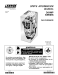
G32V series units are high−efficiency upflow gas furnaces manufactured with
DuralokPlus aluminized steel clamshell-type heat exchangers. G32V units
are available in heating capacities of 75,000 to 125,000 Btuh and cooling applications up to 5 tons. Refer to Engineering Handbook for proper sizing.
Units are factory equipped for use with natural gas. LP kits are available. All
G32V−1 through −4 units feature the Lennox SureLight silicon nitride ignition
system. G32V−5 and later units feature the two stage variable speed SureLight
integrated control board.The G32V units meet the California Nitrogen Oxides
(NOx) Standards and California Seasonal Efficiency requirements without modification. All units use a two−stage gas valve along with a two−stage combustion
air blower. The gas valve is redundant to assure safety shut−off as required by
A.G.A. or C.G.A.
All G32V units are equipped with an electronic variable speed (VSM) fan motor. The VSM consists of an ICM2 motor and control module assembly. The
VSM maintains a specified air volume throughout the entire external static
range.
Information contained in this manual is intended for use by qualified service
technicians only. All specifications are subject to change. Procedures outlined
in this manual are presented as a recommendation only and do not supersede
or replace local or state codes. In the absence of local or state codes, the
guidelines and procedures outlined in this manual (except where noted) are
recommended only.
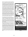
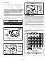
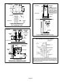
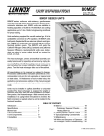
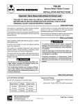
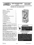
G32V FURNACE
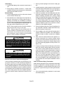
G32V HEAT EXCHANGE ASSEMBLY
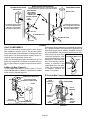
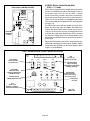
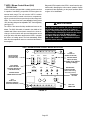
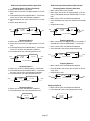
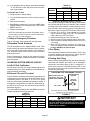
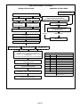
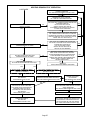
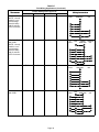
Combustion Process:
1. A call for heat starts the combustion air blower.
2. Outdoor air is drawn through pipe into the burner
compartment where it mixes with gas in a conventional style inshot burner.
3. The SureLight ignition system lights the burners.
4. Combustion products are drawn downward
through the heat exchanger. Heat is extracted
as indoor air passes across the outside surface
of the metal.
5. Latent heat is removed from the combustion
products as air passes through the coil. Condensate (water) is formed as the combustion products cool.
6. As the combustion products exit the coil, condensate is collected and drained away.
7. Combustion products are pulled from the heat
exchanger and forced into the flue.
Page 1
© 1998 Lennox Industries Inc.
Litho U.S.A.
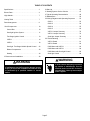
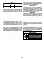
TABLE OF CONTENTS
Specifications . . . . . . . . . . . . . . . . . . . . . . . . . . . . . . . . . 3
Blower Data . . . . . . . . . . . . . . . . . . . . . . . . . . . . . . . . . . 4
III Start Up . . . . . . . . . . . . . . . . . . . . . . . . . . . . . . . . . . . . 46
IV Heating System Service Checks . . . . . . . . . . . . . . 47
V Typical Operating Characteristics . . . . . . . . . . . . . . 49
High Altitude . . . . . . . . . . . . . . . . . . . . . . . . . . . . . . . . . . 7
VI Maintenance . . . . . . . . . . . . . . . . . . . . . . . . . . . . . . . 50
Venting Table . . . . . . . . . . . . . . . . . . . . . . . . . . . . . . . . . 7
VII Wiring Diagrams and Operating Sequence . . . . 53
G32V−1 . . . . . . . . . . . . . . . . . . . . . . . . . . . . . . . . . . 53
Parts Arrangement . . . . . . . . . . . . . . . . . . . . . . . . . . . . 8
G32V−3 . . . . . . . . . . . . . . . . . . . . . . . . . . . . . . . . . . 54
I Unit Components . . . . . . . . . . . . . . . . . . . . . . . . . . . . 10
G32V−4 . . . . . . . . . . . . . . . . . . . . . . . . . . . . . . . . . . 55
Control Box . . . . . . . . . . . . . . . . . . . . . . . . . . . . . . . 10
G32V−5 . . . . . . . . . . . . . . . . . . . . . . . . . . . . . . . . . . 62
VSP2−1 Jumper Summary . . . . . . . . . . . . . . . . . . 70
SureLight Ignition System . . . . . . . . . . . . . . . . . . . 11
VSP3−1 Jumper Summary . . . . . . . . . . . . . . . . . . 74
Two−Stage Ignition Control . . . . . . . . . . . . . . . . . . 13
VSP2−1 . . . . . . . . . . . . . . . . . . . . . . . . . . . . . . . . . . . 14
SureLight Jumper Summary . . . . . . . . . . . . . . . . 78
VIII Troubleshooting . . . . . . . . . . . . . . . . . . . . . . . . . . . 81
VSP2−1 Board . . . . . . . . . . . . . . . . . . . . . . . . . . . . . 81
VSP3−1 . . . . . . . . . . . . . . . . . . . . . . . . . . . . . . . . . . . 18
VSP3−1 Board . . . . . . . . . . . . . . . . . . . . . . . . . . . . . 82
ICM2 Motor with VSP2−1 . . . . . . . . . . . . . . . . . . . 83
SureLight Two Stage Variable Speed Control . 22
ICM2 Motor with VSP3−1 . . . . . . . . . . . . . . . . . . . 84
Blower Compartment . . . . . . . . . . . . . . . . . . . . . . . 30
ICM2 Motor with SureLight Control . . . . . . . . . . . 85
Heating . . . . . . . . . . . . . . . . . . . . . . . . . . . . . . . . . . 34
SureLight Control . . . . . . . . . . . . . . . . . . . . . . . . . 86
II Placement and Installation . . . . . . . . . . . . . . . . . . . . 38
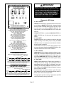
WARNING
WARNING
Electric shock hazard. Can cause injury
or death. Before attempting to perform
any service or maintenance, turn the
electrical power to unit OFF at disconnect switch(es). Unit may have multiple
power supplies.
Improper installation, adjustment, alteration, service
or maintenance can cause property damage, personal injury or loss of life. Installation and service must
be performed by a qualified installer or service
agency.
Page 2
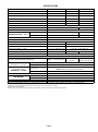
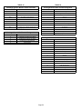
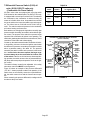
SPECIFICATIONS
Model No.
G32V3−75
G32V5−100
G32V5−125
Input Btuh (kW) − High
75,000 (22.0)
100,000 (29.3)
125,000 (36.6)
Input Btuh (kW) − Low
51,000 (14.9)
68,000 (19.9)
85,000 (24.9)
Output Btuh (kW) − High
67,500 (19.8)
90,000 (26.4)
112,500 (32.9)
Output Btuh (kW) − Low
45,900 (13.4)
61,200 (17.9)
76,500 (22.4)
A.F.U.E.
92.7%
93.2%
94.2%
California Seasonal Efficiency
89.4%
90.1%
91.1%
Exhaust pipe connection (PVC) diameter in. (mm)
2 (51)
Intake pipe connection (PVC) diameter in. (mm)
2 (51)
Condensate drain connection (PVC) in. (mm)
Temperature rise range F (C)
3 (76)
1/2 (12.7)
Low Fire
30 − 60(16 − 33)
35 − 65 (19 − 36)
High Fire
40 − 70 (22 − 39)
50 − 80 (28 − 44)
High static certified by (A.G.A./C.G.A.) in. wg. (Pa)
.80 (200)
Gas Piping Size I.P.S. − Natural − in. (mm)
1/2 (12.7)
Blower wheel nominal diameter x width − in. (mm)
10 x 8 (254 x 203)
11−1/2 x 9 (292 x 229)
1/2
1
Blower motor output hp (W)
Nominal cooling that can be added − Tons (kW)
No. & size of filters − in. (mm)
2 to 3 (7 to 10.6)
3−1/2 to 5 (12.3 to 17.6)
(1) 14 x 25 x 1 (356 x 635 x 25)
(1) 20 x 25 x 1 (508 x 635 x 25)
Shipping weight lbs. (kg) 1 package
161 (73)
Electrical characteristics
201 (91)
221 (100)
120 volts 60 hertz 1 phase (less than 12 amps)
OPTIONAL ACCESSORIES (Must Be Ordered Extra)
Concentric Vent/Intake Air/Roof Termination Kit
Vent/Intake Air Roof
Termination Kit vent size
Vent/Intake Air Wall
Termination Kit vent size
60G77 1/1/2 inch (38 mm)
2 inch (51 mm)
33K97− 2 inch (51 mm)
60L46 − 3 inch (76 mm)
15F75
3 inch (76 mm)
44J41
2 inch (51 mm)
15F74 (ring kit) 22G44 (close couple) 30G28 (WTK close couple)
30G79 (WTKX close couple with extension riser)
3 inch (76 mm)
44J40 (close couple) 81J20 (WTK close couple)
Condensate Drain Heat Cable
Heat Cable Tape
33K97 2 inch
(51 mm)
26K68 6 ft. (1.8 m) − 26K69 24 ft. (7.3 m) − 26K70 50 ft. (15.2 m)
Fiberglass − 1/2 in. (38 mm)
39G04
Aluminum foil − 2 in. (25 mm)
39G03
L.P. Kit
34L29 (−1, −2 models) 11M55 (−3 and later models)
Annual Fuel Utilization Efficiency based on U.S. DOE test procedures and FTC labeling regulations. Isolated combustion system rating for non−weatherized furnaces.
Meets California Nitrogen Oxides (NOx) Standard and California Seasonal Efficiency requirements.
Determine from venting tables proper intake and exhaust pipe size and termination kit required.
Polyurethane frame type filter.
NOTE − 2 inch x 3 inch (51 mm x 76 mm) adaptor is furnished with −100 and −125 furnaces for exhaust pipe connection.
Page 3
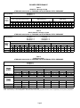
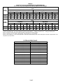
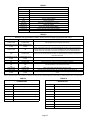
BLOWER PERFORMANCE
Table 1
G32V3−75−1 through −3 Units
0 THROUGH 0.80 IN. W.G. (0 THROUGH 200 PA) EXTERNAL STATIC PRESSURE
VSP2-1 Blower Control
Factory Settings
Low Speed 3
High Speed 4
Heat Speed 3
VSP2−1 Jumper Speed Positions
LOW" Speed
(Cool, Low Heat Or Continuous Fan)
ADJUST"
Jumper
Setting
1
2
3
HIGH" Speed (Cool)
4
cfm
1
cfm
L/s
cfm
L/s
L/s
L/s
cfm
L/s
930
440
980
465 1040 490 1060 500 1105 520 1260 595 1330 630 1075 510 1150 545 1270 600 1350 635
− 15%
775
365
810
380
850
400
930
440
cfm
990
L/s
cfm
4
cfm
460 1070 505 1130 535
cfm
3
L/s
970
cfm
2
415
440
L/s
1
880
930
cfm
4
cfm
430
L/s
3
NORM
910
L/s
2
HEAT" Speed
L/s
cfm
L/s
465 1080 510 1140 540
NOTE The effect of static pressure and filter resistance is included in the air volumes listed.
Table 2
G32V5−100/125−1 through −3 Units
0 THROUGH 0.80 IN. W.G. (0 THROUGH 200 PA) EXTERNAL STATIC PRESSURE
VSP2-1 Blower Control
Factory Settings
G32V5−100
Low Speed 2
High Speed 4
Heat Speed 1
G32V5−125
Low Speed 3
High Speed 4
Heat Speed 2
VSP2 Jumper Speed Positions
ADJUST"
Jumper
Setting
LOW" Speed (Cool Or Continuous Fan)
1
2
3
4
HIGH" Speed (Cool)
1
2
HEAT" Speed
3
1
4
2
3
4
cfm L/s cfm L/s cfm L/s cfm L/s cfm L/s cfm L/s
cfm
L/s
cfm
L/s
cfm L/s cfm L/s
cfm
L/s
cfm
L/s
NORM
1140 540 1250 590 1440 680 1550 730 1620 765 1820 860
2000
945
2100
990
1560 735 1720 810
2030
960
2150
1015
−
970 460 1060 500 1280 605 1320 625 1380 650 1550 730
1700
800
1780
840
1330 630 1460 690
1730
815
1830
865
NOTE The effect of static pressure and filter resistance is included in the air volumes listed.
G32V5−125 unit only − do not place jumper on tap 1 ("") for high speed or tap 2 ("NORM" or "") for low speed.
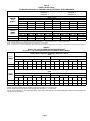
Table 3
G32V3−75−4 Units
0 THROUGH 0.80 IN. W.G. (0 THROUGH 200 PA) EXTERNAL STATIC PRESSURE
VSP3−1 Blower Control Factory Settings
ADJUST − NORM
Heat Speed − 3
Cool Speed − 4
VSP Jumper Speed Positions
HEAT" Jumper
ADJUST"
Jumper
P iti
Positions
Low Speed
1
2
High Speed
3
4
1
2
3
4
cfm
L/s
cfm
L/s
cfm
L/s
cfm
L/s
cfm
L/s
cfm
L/s
cfm
L/s
cfm
L/s
NORM (Normal)
880
415
930
440
980
465
1040
490
1075
510
1150
545
1270
600
1350
635
" (Minus) 15%
775
365
810
380
850
400
910
430
930
440
990
460
1080
510
1140
540
COOL" Jumper
ADJUST"
Jumper
Positions
Low Speed
1
2
High Speed
3
4
1
2
3
4
cfm
L/s
cfm
L/s
cfm
L/s
cfm
L/s
cfm
L/s
cfm
L/s
cfm
L/s
cfm
L/s
NORM (Normal)
880
415
930
440
980
465
1040
490
1060
500
1105
520
1260
600
1350
635
" (Minus) 15%
775
365
810
380
850
400
910
430
930
440
970
460
1080
510
1140
540
15% lower motor speed than NORM jumper setting.
NOTE − The effect of static pressure and filter resistance is included in air volumes shown.
NOTE − Continuous Fan only speed is approximately 800 cfm (380 L/s) − non adjustable.
NOTE − Lennox Harmony II zone control applications − MAX CFM is determined by COOL jumper placement with a minimum of approximately 850 cfm (400 L/s) for all positions.
Page 4
Table 4
G32V5−100/125−4 Units
0 THROUGH 0.80 IN. W.G. (0 THROUGH 200 PA) EXTERNAL STATIC PRESSURE
VSP3−1 Blower Control Factory Settings
G32V5−100
ADJUST − NORM
Heat Speed − 2
Cool Speed − 4
G32V5−125 ADJUST − (minus)
Heat Speed − 4
Cool Speed − 4
VSP Jumper Speed Positions
HEAT" Jumper
ADJUST"
Jumper
P iti
Positions
Low Speed
1
2
High Speed
3
1
4
2
3
4
cfm
L/s
cfm
L/s
cfm
L/s
cfm
L/s
cfm
L/s
cfm
L/s
cfm
L/s
cfm
L/s
NORM (Normal)
1140
540
1250
590
1440
680
1550
730
1560
735
1720
810
2030
955
2150
1015
" (Minus) 15%
970
455
1060
500
1280
605
1320
595
1330
625
1460
690
1730
815
1830
865
COOL" Jumper
ADJUST"
Jumper
Positions
Low Speed
1
2
High Speed
3
4
1
2
3
4
cfm
L/s
cfm
L/s
cfm
L/s
cfm
L/s
cfm
L/s
cfm
L/s
cfm
L/s
cfm
L/s
NORM (Normal)
1140
540
1250
590
1440
680
1550
730
1620
765
1820
860
2000
945
2100
990
" (Minus) 15%
970
455
1060
500
1280
605
1320
595
1380
650
1550
730
1700
800
1780
840
15% lower motor speed than NORM jumper setting.
G32V5−125 Models Only − Do not place jumper on position #1 (at NORM or " setting) or position #2 (at " setting) for HEAT speed.
NOTE − The effect of static pressure and filter resistance is included in air volumes shown.
NOTE − Continuous Fan only speed is approximately 1150 cfm (545 L/s) − non adjustable.
NOTE − Lennox Harmony II zone control applications − MAX CFM is determined by COOL jumper placement with a minimum of approximately 1140 cfm (540 L/s) for all positions.
TABLE 5
G32V3−75−5 Units BLOWER MOTOR PERFORMANCE
0.0" to 0.8" w.g. (0 through 200 Pa) External Static Pressure Range
Blower Speed Adjustment Settings (Switches 5 and 6)
Cool
Adjust"
Setting
Low Speed
1
2
High Speed
3
4
1
2
3
4
cfm
L/s
cfm
L/s
cfm
L/s
cfm
L/s
cfm
L/s
cfm
L/s
cfm
L/s
cfm
L/s
Norm
880
415
930
440
980
465
1040
490
1060
500
1105
520
1260
595
1330
630
–
775
365
810
380
850
400
910
430
930
440
970
460
1070
505
1130
535
Blower Speed Adjustment Settings (Switches 7 and 8)
Heat
Adjust"
Setting
Low Speed
1
2
High Speed
3
4
1
2
3
4
cfm
L/s
cfm
L/s
cfm
L/s
cfm
L/s
cfm
L/s
cfm
L/s
cfm
L/s
cfm
L/s
Norm
945
446
1025
484
1125
531
1270
599
1080
510
1172
533
1286
607
1452
685
–
803
379
871
411
956
451
1080
510
918
433
996
470
1093
516
1234
582
15% lower motor speed than NORM switch setting.
NOTE − The effect of static pressure and filter resistance is included in air volumes shown.
NOTE − Continuous Fan only speed is approximately 800 cfm (380 L/s) − non adjustable.
NOTE − Lennox Harmony IIt zone control applications − MAX CFM is determined by COOL switch setting with a minimum of approximately 850
cfm (400 L/s) for all positions.
Page 5
TABLE 6
G32V5−100/125−5 Units BLOWER MOTOR PERFORMANCE
0.0" to 0.8" w.g. (0 through 200 Pa) External Static Pressure Range
Blower Speed Adjustment Settings (Switches 5 and 6)
Cool
Adjust"
Setting
Low Speed
1
2
High Speed
3
1
4
2
3
4
cfm
L/s
cfm
L/s
cfm
L/s
cfm
L/s
cfm
L/s
cfm
L/s
cfm
L/s
cfm
L/s
Norm
1140
540
1250
590
1440
680
1550
730
1620
765
1820
860
2000
945
2100
990
–
970
455
1060
500
1280
605
1320
595
1380
650
1550
730
1700
800
1780
840
Blower Speed Adjustment Settings (Switches 7 and 8)
Heat
Adjust"
Setting
Low Speed
1
2
High Speed
3
4
1
2
3
4
cfm
L/s
cfm
L/s
cfm
L/s
cfm
L/s
cfm
L/s
cfm
L/s
cfm
L/s
cfm
L/s
Norm
1140
540
1250
590
1440
680
1550
730
1560
735
1720
810
2030
960
2150
1015
–
970
455
1060
500
1280
605
1320
595
1330
660
1460
690
1730
815
1830
865
15% lower motor speed than NORM switch setting.
G32V5−125 Models Only − Do not set switches for position #1 (at NORM or –" setting) or position #2 (at −" setting) for HEAT speed.
NOTE − The effect of static pressure and filter resistance is included in air volumes shown.
NOTE − Continuous Fan only speed is approximately 1150 cfm (545 L/s) − non adjustable.
NOTE − Lennox Harmony IIt zone control applications − MAX CFM is determined by COOL switch setting with a minimum of approximately 1140
cfm (540 L/s) for all positions.
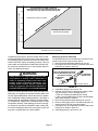
FILTER AIR RESISTANCE
cfm (L/s)
in. w.g. (Pa)
0 (0)
0.00 (0)
200 (95)
0.01 (0)
400 (190)
0.03 (5)
600 (285)
0.04 (10)
800 (380)
0.06 (15)
1000 (470)
0.09 (20)
1200 (565)
0.12 (30)
1400 (660)
0.15 (35)
1600 (755)
0.19 (45)
1800 (850)
0.23 (55)
2000 (945)
0.27 (65)
2200 (1040)
0.33 (80)
2400 (1130)
0.38 (95)
2600 (1225)
0.44 (110)
Page 6
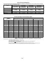
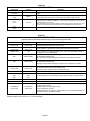
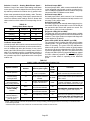
HIGH ALTITUDE INFORMATION
No gas pressure adjustment is needed when operating from 0 to 4500 ft. (0 to 8 m). See below for correct manifold pressures for altitudes
greater that 4500 ft. (1372 m) for natural and L.P. gas.
Manifold Absolute Pressure (outlet) in. w.g. (kPa)
Model No.
4501 to 5500 ft.
(1373 to 1676 m)
above sea level
0 to 4500 ft. (0 to 1372 m)
above sea level
G32V−75 natural
5501 to 6500 ft.
(1677 to 1981 m)
above sea level
6501 to 7500 ft.
(1982 to 2286 m)
above sea level
no adjustment
G32V−100 natural
3 5 (0.88)
3.5
(0 88)
3 4 (0.85)
3.4
(0 85)
G32V−100 L.P.
7.5 (0.19)
G32V−125 L.P.
7.5 (0.19)
G32V−125 natural
3 3 (0.82)
3.3
(0 82)
3 2 (0.80)
3.2
(0 80)
7.3 (0.185)
7.1 (0.180)
7.0 (0.177)
7.3 (0.185)
7.1 (0.180)
7.0 (0.177)
G32V−75 L.P.
no adjustment
INTAKE AND EXHAUST PIPE VENTING TABLE
Vent Pipe
Maximum
Equivalent Length
Minimum Vent Pipe Diameter Required
75,000 Btuh (22.0 kW)
100,000 Btuh (29.3 kW)
125,000 Btuh (36.6 kW)
Feet
Meters
in.
mm
in.
mm
in.
mm
15
4.6
2
51
2
51
2
51
20
6.1
2
51
2
51
3
76
25
7.6
2
51
2
51
3
76
30
9.1
2
51
3
51
3
76
40
12.2
2
51
3
51
3
76
50
15.2
2
51
3
51
3
76
55
16.8
2
51
3
76
3
76
60
18.3
3
76
3
76
3
76
70
21.3
3
76
3
76
3
76
80
24.4
3
76
3
76
3
76
90
27.4
3
76
3
76
3
76
100
30.5
3
76
3
76
3
76
110
33.5
3
76
3
76
3
76
120
36.6
3
76
3
76
3
76
130
39.6
3
76
3
76
−−−−
−−−−
MINIMUM PIPE LENGTHS FOR FURNACES G32V−75 5 feet (1.5 m) with two 90 elbows of 2 inch (51 mm) diameter pipe. (15 equivalent feet (4.6 m) total).
G32V−100 5 feet (1.5 m) with two 90 elbows of 2 inch (51 mm) diameter pipe. (15 equivalent feet (4.6 m) total).
G32V−125 5 feet (1.5 m) with two 90 elbows of 2 inch (51 mm) diameter pipe. (15 equivalent feet (4.6 m) total).
VENTING NOTES One 90elbow is equivalent to 5 feet (1.5 m) of straight vent pipe.
Two 45 elbows are equal to one 90 elbow.
One 45 elbow is equivalent to 2.5 feet (.75 m) of straight vent pipe.
One foot (305 mm) length of 2 in. (51 mm) diameter pipe is equivalent to 8 feet (2.4 m) of 3 in. (76 mm) diameter pipe.
Intake and Exhaust pipes must be the same diameter.
2 inch x 3 inch (51 mm x 76 mm) adaptor is furnished with −100 and −125 furnaces for exhaust pipe connection.
Exhaust pipe must terminate with 1−1/2 inch (38 mm) diameter pipe for furnaces using1−1/2 (38 mm) or 2 inch (51 mm) diameter pipe runs.
Exhaust pipe must terminate with 2 inch (51 mm) diameter pipe for furnaces using 3 inch (76 mm) diameter pipe runs.
Page 7
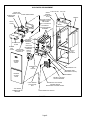
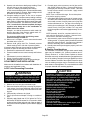
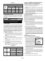
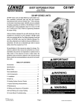
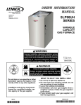
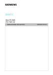
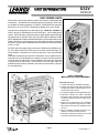
G32V PARTS ARRANGEMENT
FRESH AIR
INTAKE FITTING
GLASS FIBER GASKET
BURNER BOX
ASSEMBLY
FLUE COLLAR
WARM
HEADER
(COLLECTOR)
BOX
TOP CAP
CABINET
PATCH PLATE WITH
BARBED FITTING
AND FLAME
ROLL−OUT SWITCH
PATCH
PLATE
FLUE
TRANSITION
DuralokPlusTM
HEAT EXCHANGER
ASSEMBLY
FLAME SIGHT
GLASS
BURNER
BOX
COVER
LOW HEAT
DIFFERENTIAL
PRESSURE
SWITCH
HIGH HEAT
DIFFERENTIAL
PRESSURE
TWO-STAGE
SWITCH
GAS VALVE AND
(−75 only)
MANIFOLD
SUPPLY
AIR
BLOWER
BURNER
ACCESS
PANEL
COMBUSTION
AIR
ORIFICE
SECONDARY COIL
PRIMARY LIMIT
(ALTERNATE STYLES)
BLOWER
ACCESS
DOOR
TRANSFORMER
CONTROL VOLTAGE
CIRCUIT BREAKER
COLD HEADER
(COLLECTOR)
BOX
TWO−SPEED
COMBUSTION AIR
INDUCER
SURELIGHT TWO−STAGE,
VARIABLE−SPEED
INTEGRATED CONTROL BOARD
DOOR INTERLOCK SWITCH
FIGURE 1
Page 8
BURNER BURNER BOX
FRESH AIR INTAKE
FITTING
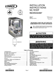
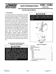
G32V HEAT EXCHANGER
CORBEL ORIFICE
CUPS
SURELIGHT IGNITOR
LENNOX DURALOKPLUS
HEAT EXCHANGER ASSEMBLY
ACCESS
COVER
MANIFOLD
GAS VALVE
WARM HEADER
(COLLECTOR)
BOX
COMBUSTION AIR
BLOWER MOTOR
COMBUSTION
AIR BLOWER
COLD HEADER
(COLLECTOR )
BOX
CONDENSER COIL
FIGURE 2
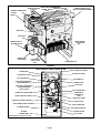
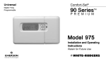
G32V GENERAL PARTS ORIENTATION
SUPPLY AIR DUCT FLANGE
BURNER BOX
UPPER VEST PANEL
FLAME SIGHT GLASS
FLUE TRANSITION
GAS MANIFOLD
LOW HEAT DIFFERENTIAL
PRESSURE SWITCH
PRIMARY LIMIT
GAS VALVE
HIGH HEAT DIFFERENTIAL
PRESSURE SWITCH
(G32V−75 ONLY)
COLD HEADER BOX
COMBUSTION AIR BLOWER
HEADER BOX
CONDENSATE
TRAP
DOOR INTERLOCK SWITCH
LOWER VEST PANEL
SURELIGHT CONTROL BOARD*
CONTROL BOX
VSP BLOWER CONTROL BOARD*
CIRCUIT BREAKER
BLOWER HOUSING
TWO−STAGE CONTROL*
BLOWER MOTOR
BLOWER
COMPARTMENT
COIL CHOKE
*NOTE−G32V−1 through −4 units only
FIGURE 3
Page 9
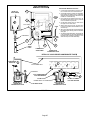
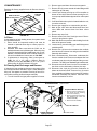
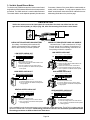
MAKE-UP BOX INSTALLATION
OUTSIDE INSTALLATION
Box may be installed inside or outside cabinet and
may be installed on left side or right side of cabinet
MAKE-UP BOX
INSIDE INSTALLATION
STAR WASHERS
MUST BREAK
PAINT ON UNIT
CABINET FOR
PROPER GROUND.
MAKE-UP BOX
UNIT
CABINET
Line Voltage Enters Through
Knockout In Make-Up Box.
J69 Passes Through Side
Knockout Into Side Of Unit.
Line Voltage Enters Make-Up
Box Through Side Of Unit and
J69 Passes Through Bottom
Knockout in Make-Up Box.
JACK J69
BLOWER MULLION
BLOWER MULLION
PLUG P69
FIGURE 4
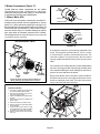
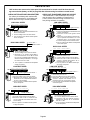
An accessory (brown) output wire is provided with the make-up
box. The wire provides a 120V connection for optional accesG32V unit components are shown in figures 1 and 2. General
sories such as electronic air cleaner or humidifier. If used, the
parts orientation is shown in figure 3. The gas valve, ignition
wire is field installed in J69 jack plug by inserting the pin of the
control and burners can be accessed by removing the burner
brown wire into the open socket
INSTALLING BROWN
access panel. The blower and blower controls can be acof the jack. See figure 6. 120V ACCESSORY WIRE TO J69
cessed by removing the blower access door.
accessories rated up to 4 amps
BROWN
G32V units are designed for bottom and side return air. The
total may be connected to this
panels are designed to be knocked-out (bottom return) or
wire. The neutral leg of the ac- WHITE
cut-out (side return) as required for return air duct conneccessory is connected to the NEUTRAL
tion.
neutral white wire in the makeA−Make-Up Box (Figure 5)
up box. The accessory terminal
BLACK
is energized whenever the
The line voltage make-up box is shown in figure 5. The box
blower is in operation.
may be installed inside or outside the unit and may be installed
J69
on the unit left or right side (figure 4).
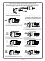
I−UNIT COMPONENTS
MAKE-UP BOX
POWER ENTRY KNOCKOUT
BOX
120V LINE VOLTAGE
PIGTAIL CONNECTIONS
COVER
B−Control Box Components
FIGURE 6
G32V−1 through −4 CONTROL BOX
DOOR
INTERLOCK
SWITCH
TRANSFORMER
CIRCUIT
BREAKER
UNIT
GROUND
SURELIGHT
CONTROL
JACK J69
to blower deck
VSP
BOARD TERMINAL STRIP
TO BLOWER MULLION
Box may be installed inside or outside unit. See Figure 4.
FIGURE 5
FIGURE 7
Page 10
TWO−
STAGE
CONTROL
BOARD
Integrated ignition and blower control components (A92),
unit transformer (T1) and 24V circuit breaker (CB8) are located in the control box. In addition, a door interlock switch
(S51) is located in the control box. Jackplugs allow the control box to be easily removed for blower service.
1. Control Transformer (T1)
A transformer located in the control box provides power to
the low voltage 24volt section of the unit. Transformers on
all models are rated 50VA with a 120V primary and a 24V
secondary.
2. Circuit Breaker (CB8)
A 24V circuit breaker is also located in the control box. The
switch provides overcurrent protection to the transformer
(T1). The breaker is rated 3A . If the current exceeds this limit
the breaker will trip and all unit operation will shut-down. The
breaker can be manually reset by pressing the button on the
face.
NOTE − Do not remove blower access panel to read
SureLight LED lights. A sight glass is provided on the
access panel for viewing.
Tables 9 and 10 show jack plug terminal designations.
Units equipped with the SureLight board can be used with
either electronic or electro−mechanical thermostats without modification. The SureLight ignitor is made of durable
silicon−nitride. Ignitor longevity is also enhanced by voltage ramping by the control board. The board finds the lowest ignitor temperature which will successfully light the
burner, thus increasing the life of the ignitor.
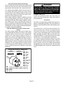
SURELIGHT CONTROL BOARD
3.Door Interlock Switch (S51)
A door interlock switch is located on the control box. The
switch is wired in series with line voltage. When the blower
door is removed the unit will shut down.
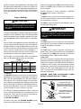
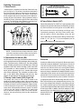
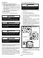
ELECTROSTATIC DISCHARGE (ESD)
Precautions and Procedures
CAUTION
Electrostatic discharge can affect electronic
components. Take precautions during furnace
installation and service to protect the furnace’s
electronic controls. Precautions will help to
avoid control exposure to electrostatic discharge by putting the furnace, the control and
the technician at the same electrostatic potential. Neutralize electrostatic charge by touching
hand and all tools on an unpainted unit surface,
such as the gas valve or blower deck, before performing any service procedure.
FIGURE 8
DANGER
Disconnect power before servicing. Control is not
field repairable. If control is inoperable, simply
replace entire control.
Can cause injury or death. Unsafe operation will
result if repair is attempted.
SURELIGHT IGNITOR
5/8"
MEASUREMENT IS TO I.D.
OF RETENTION RING
13/32’
4.SureLight Ignition System A92
G32V−1 through −4 units are equipped with the Lennox
SureLight ignition system. The system consists of ignition
control board (figure 8 with control terminal designations
in table 1) and ignitor (figure 9). The board and ignitor work
in combination to ensure furnace ignition and ignitor durability. The SureLight integrated board controls all major furnace operations. The board also features two LED lights
for troubleshooting (and two accessory terminals rated at
(4) four amps. See table 8 for troubleshooting diagnostic
codes.
Page 11
5/16
"
FIGURE 9
TABLE 7
SURELIGHT CONTROL TERMINAL DESIGNATIONS
ACB COOL
NOT USED
ACB HEAT
NOT USED
PARK
NOT USED
ACB LOW
NOT USED
ACC
ACCESSORY TERMINAL (LINE VOLT)
TX
120VAC TRANSFORMER
HOT
120VAC HOT INPUT
HTG ACC
HEAT ONLY ACCESSORY (LINE VOLT)
NEUTRALS
120VAC NEUTRALS
24VAC HOT
24VAC HOT FROM TRANSFORMER
24VAC RTN
24VAC RETURN FROM TRANSFORMER
FLAME SENSE
FLAME SENSE TERMINAL
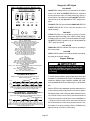
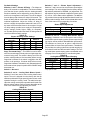
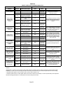
TABLE 8
DIAGNOSTIC CODES
MAKE SURE TO ID LED’S CORRECTLY: REFER TO INSTALLATION INSTRUCTIONS FOR CONTROL BOARD LAYOUT.
LED #1
LED #2
DESCRIPTION
SIMULTANEOUS
SLOW FLASH
SIMULTANEOUS
SLOW FLASH
Power − Normal operation
Also signaled during cooling and continues fan.
SIMULTANEOUS FAST
FLASH
SIMULTANEOUS FAST
FLASH
Normal operation − signaled when heating demand initiated at thermostat.
SLOW FLASH
ON
OFF
SLOW FLASH
ALTERNATING SLOW
FLASH
ALTERNATING SLOW
FLASH
SLOW FLASH
ON
ON
ON
OFF
FAST FLASH
SLOW FLASH
ALTERNATING FAST
FLASH
OFF
SLOW FLASH
ON
OFF
ON
SLOW FLASH
FAST FLASH
ALTERNATING FAST
FLASH
Primary or Secondary limit open. Units with board 63K89 or 24L85: Limit must close within 5
trials for ignition or board goes into one hour limit Watchguard. Units with board 56L83 or
97L48: Limit must close within 3 minutes or board goes into one hour limit Watchguard.
Pressure switch open or has opened 5 times during a single call for heat; OR: Blocked inlet/
exhaust vent; OR: Condensate line blocked; OR: Pressure switch closed prior to activation of
combustion air blower.
Watchguard − burners fail to ignite.
Flame sensed without gas valve energized.
Rollout switch open. OR: 9 pin connector improperly attached.
Circuit board failure or control wired incorrectly.
Main power polarity reversed. Switch line and neutral.
Low flame signal. Measures below .61 microAmps. Replace flame sense rod.
Improper main ground or line voltage below 75 volts; OR: Broken ignitor; OR: Open ignitor
circuit.
NOTE − Slow flash equals 1 Hz (one flash per second). Fast flash equals 3 Hz (three flashes per second). Drop out flame sense current < 0.20 microAmps
TABLE 9
TABLE 10
SureLight BOARD J156 TERMINAL
DESIGNATIONS
SureLight BOARD J58 TERMINAL
DESIGNATIONS
PIN #
FUNCTION
PIN #
FUNCTION
1
Ignitor
1
Primary Limit In
2
Not Used
2
Gas Valve Common
3
Ignitor Neutral
3
Roll Out Switch Out
4
Combustion Air Blower Line Voltage
4
Gas Valve 24V
5
Not Used
5
Pressure Switch In
6
Combustion Air Blower Neutral
6
Pressure Switch and Primary Limit Out
7
Not Used
8
Roll Out Switch In
9
Ground
Page 12
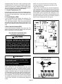
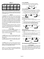
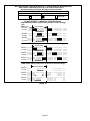
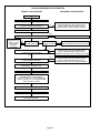
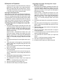
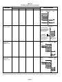
Electronic Ignition (See Ignition Sequence Below)
On a call for heat the SureLight control monitors the combustion air blower pressure switch. The control will not begin the heating cycle if the pressure switch is closed (by−
passed). Once the pressure switch is determined to be
open, the combustion air blower is energized. When the differential in the pressure switch is great enough, the pressure switch closes and a 15−second pre−purge begins. If the
pressure switch is not proven within 2−1/2 minutes, the control goes into Watchguard−Pressure Switch mode for a
5−minute re−set period.
After the 15−second pre−purge period, the SureLight ignitor
warms up for 20 seconds after which the gas valve opens
for a 4−second trial for ignition. G32V units with board
24L85, 56L83 or 63K89: the ignitor energizes for the first
second of the 4−second trial. Units equipped with board
97L48: ignitor energizes during the trial until flame is
sensed. If ignition is not proved during the 4−second period,
the control will try four more times with an inter purge and
warm−up time between trials of 35 seconds. After a total of
five trials for ignition (including the initial trial), the control
goes into Watchguard−Flame Failure mode. After a 60−minute reset period, the control will begin the ignition sequence
again.
The SureLight control board has an added feature that prolongs the life of the ignitor. After a successful ignition, the
SureLight control utilizes less power to energize the ignitor
on successive calls for heat. The control continues to ramp
down the voltage to the ignitor until it finds the lowest
amount of power that will provide a successful ignition. This
amount of power is used for 255 cycles. On the 256th call
for heat, the control will again ramp down until the lowest
power is determined and the cycle begins again.
É
É
É
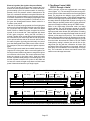
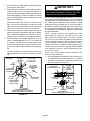
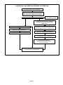
5. Two−Stage Control (A86)
G32V−1 through −4 units
G32V−1 through −4 units are equipped with a two−stage
control (figure 10). The two−stage board acts as a go between from the indoor thermostat to the SureLight ignition
board. The board can be utilized in three modes: with a
SINGLE−STAGE thermostat, a TWO−STAGE thermostat or
with a second−stage (high fire) delay called W2 TIMED. The
two−stage board is equipped with a jumper (see figure 10)
which changes operating modes and a jumper which adjusts second−stage heat delay during W2 TIMED mode.
While in the single−stage thermostat mode (one−stage
jumper setting), the unit will always operate on second−
stage heat. The combustion air blower (B6) will operate on
high speed and indoor blower (B3) will operate on heating
speed. While in the two−stage thermostat mode the unit will
operate on first−stage heat (low fire). The combustion air
blower (B6) and indoor blower will operate on low speed.
The unit will switch to second−stage heat (high fire) on call
from the indoor thermostat W2. While in the W2 TIMED
mode (factory setting 8 minutes) the unit will fire on first−
stage heat (low fire) with the combustion air blower (B6)
and indoor blower (B3) operating on low speed. After a set
time delay the unit switches to second−stage heat (high
fire). The combustion air blower and indoor blower also
switch to second−stage heat mode.
Ignition Sequence Board: 63K89, 24L85 and 56L8301
1
ON
OFF
34 35
15
38
80
5 SEC
ÉÉÉÉÉÉÉÉÉÉÉÉÉÉÉÉÉÉÉÉÉÉÉÉÉ
ÉÉÉÉÉÉÉÉÉÉÉÉÉÉÉÉÉÉÉÉÉÉÉÉÉ
ÉÉÉÉÉÉÉÉÉÉÉÉÉÉÉÉÉÉÉÉÉÉÉÉÉÉÉ
ÉÉÉÉÉÉÉÉ
ÉÉÉÉÉÉÉÉ
ÉÉÉÉÉÉÉÉÉÉÉÉÉÉ
ÉÉÉÉÉÉÉÉÉÉÉÉÉÉ
ÉÉÉÉÉÉÉÉÉ
Pre −Purge
Ignitor Warmup
Trial for
Ignition
Blower On"
Delay
Post
Purge
DEMAND
CAB
IGNITOR
GAS VALVE
INDOOR BLOWER
É
É
Ignition Sequence Board 97L4801
15
1
ON
OFF
38
34
80
5 SEC
ÉÉÉÉÉÉÉÉÉÉÉÉÉÉÉÉÉÉÉÉÉÉÉÉÉ
ÉÉÉÉÉÉÉÉÉÉÉÉÉÉÉÉÉÉÉÉÉÉÉÉÉ
ÉÉÉÉÉÉÉÉÉÉÉÉÉÉÉÉÉÉÉÉÉÉÉÉÉÉÉ
ÉÉÉÉÉÉÉÉÉÉÉÉÉÉÉÉÉÉÉÉÉÉÉÉÉÉÉ
ÉÉÉÉÉÉÉÉÉÉ
ÉÉÉÉÉÉÉÉÉÉÉÉÉÉ
ÉÉÉÉÉÉÉÉÉÉÉÉÉÉ
ÉÉÉÉÉÉÉÉÉ
ÉÉÉÉÉÉÉÉÉ
Pre −Purge
Ignitor Warmup
Trial for
Ignition
Blower On"
Delay
Post
Purge
DEMAND
CAB
IGNITOR
GAS VALVE
INDOOR BLOWER
*All controls: blower on time will be 45 seconds after gas valve is energized. Blower off time will depend on OFF TIME" Setting.
Page 13
6.VSP2−1 Blower Control Board (A24)
G32V −1 / −3 units
TWO−STAGE CONTROL BOARD
G32V units are equipped with a variable speed motor that is
capable of maintaining a specified CFM throughout the external static range. The unit uses the VSP2−1 variable
speed control board, located in the blower compartment,
which controls the blower speed and provides diagnostic
LEDs. The control has both a non−adjustable, factory preset
ON" fan timing delay and an adjustable OFF" fan timing delay
(see figure 13).
W2 TIMED ON
DELAY JUMPER
The VSP2−1 also senses limit trip condition and turns on the
blower. The G32V limit switch is located in the middle of the
vestibule wall. When excess heat is sensed in the heat exchanger, the limit switch will open and interrupt the current
to the gas valve, while at the same time the VSP2−1 energizes
the blower on heating speed. The limit automatically resets
when the unit temperature returns to normal and the blower is
de−energized.
MODE OF
OPERATION
JUMPER
Diagnostic LEDs located on the VSP2−1 control board are provided to aid in identifying the unit’s mode of operation. Certain
scenarios will arise depending on the jumper positions. Refer
to figure 11 for identification.
FIGURE 10
VSP2−1 VARIABLE SPEED CONTROL BOARD SELECTIONS
1
JP46
13 PIN PLUG
(BOARD TO MOTOR)
JP2
HIGH SPEED
SELECTOR PINS
(COOLING ONLY)
HIGH
LOW SPEED
SELECTOR PINS
(COOLING, HEATING and
CONTINUOUS FAN)
LOW
1
HEAT
1
1
TEST
1
2
2
−
2
3
3
+
3
4
4
NORM
4
HTG.
BLOWER
HEATING STAGE
JUMPER SELECTOR PINS
ADJUST
2
HEATING SPEED
SELECTOR PINS
See table 11 for VSP2
factory settings
HEAT
DS3
HI/LOW
DS4
DS2
ON/OFF
DS1
CFM
DIAGNOSTIC
DS LEDS
90
270
210
JP73
15 PIN PLUG
(BOARD TO VARIOUS
POINTS IN FURNACE)
OPERATIONAL
SELECTOR PINS
(Affects both heating
and cooling modes)
150
JP1
FAN OFF"
TIMING PINS
1
FIGURE 11
Page 14
IMPORTANT
VSP2−1 BLOWER CONTROL BOARD (A24)
1
24 VAC half wave rectified (DC pulse), when
measured with a meter, may appear as a lower
or higher voltage depending on the make of the
meter. Rather than attempting to measure the
output voltage of A24, see G32V BLOWER &
VSP2 BLOWER CONTROL BOARD TROUBLESHOOTING FLOW CHART in the TROUBLESHOOTING section of this manual.
J46
HIGH
LOW
1
2
3
4
HTG.
BLOWER
1
ADJUST
1
2
3
4
2
HEAT
TEST
−
+
NORM
1
2
3
4
HEAT
DS3
HI/LOW
DS4
DS2
ON/OFF
DS1
CFM
Diagnostic LED Lights
a − DS3 ON/OFF"
90
270
210
ON/OFF−DS3 indicates there is a demand for the blower motor
to run. When the ON/OFF LED−DS3 is lit, a demand is being
sent to the motor. In heating mode only, there is a 45 second
fan ON" delay in energizing ON/OFF LED−DS3. The
light will not go off until adjustable fan OFF" delay has
expired.
150
J73
1
J73
PIN 1 - C - 24 VAC common.
PIN 2 - G - Input signal from thermostat’s fan signal.
PIN 3 - W2 - Input signal for second stage heat from the thermostat.
PIN 4 - DS - Input signal for the blower speed regulation.
PIN 5 - Limit - Input signal from the external limit.
PIN 6 - R - 24 VAC power to the thermostat.
PIN 7 - C - 24 VAC common.
Pin 8 - C - 24 VAC common.
PIN 9 - CI - Input signal from the fan limit control.
PIN 10 - CO - Output signal to the burner control.
PIN 11 - HT - Input signal from the fan limit control.
PIN 12 - ACC - 24 VAC accessory output.
PIN 13 - 24V - Input 24 VAC power for the VSP2-1.
PIN 14 - 24V - Input 24 VAC power for the VSP2-1.
PIN 15 - V - Input signal from the gas line.
If ON/OFF LED−DS3 is on and both HIGH/LOW LED−DS1 &
HEAT LED−DS2 are off, the motor will operate in low
speed.
b − DS2 HEAT"
If HEAT LED−DS2 is on, the blower is running in the heat
speed according to the HEAT" jumper setting. The HEAT
LED−DS2 comes on instantaneous and switches off when
the call for heat is satisfied.
J46
PIN 1 - Heat - Heat speed input signal to the ICM2 motor.
PIN 2 - C - 24 VAC common.
PIN 3 - C - 24 VAC common.
PIN 4 - High Tap - High Speed programming input.
PIN 5 - Low Tap - Low speed programming input.
PIN 6 - On / Off - On / off output signal to the ICM2 motor.
PIN 7 - Adjust Tap - ICM2 mode selection.
PIN 8 - Hi / Low - Speed regulate input signal to the ICM2 motor.
PIN 9 - Hi / Low - Speed regulate input signal to the ICM2 motor.
PIN 10 - Ref. V - ICM2 reference voltage.
PIN 11 - Heat Tap - Heating blower speed programming.
PIN 12 - C - 24 VAC common.
PIN 13 - cfm - Motor speed diagnostic signal.
NOTE−When the blower is in OFF" delay mode, the motor runs at low speed, therefore the HEAT LED−DS2 is off. It
switches off when the call for heat is satisfied.
c − DS1 HI/LOW"
HIGH/LOW LED−DS1 indicates whether the blower is operating in high or low speed. When the light is off, the blower is
running in low speed according to the LOW" jumper setting. When HIGH/LOW LED−DS1 is on, the blower is operating in high speed according to the HIGH" jumper setting.
d − DS4 CFM"
VOLTAGES INTO VSP2−1
Voltage across J73 pins 13 to 1 and 6 to 1 is 24VAC as shown here.
Refer to unit wiring diagram.
24VAC @ 60Hz.
34 volts
0
volts
−34 volts
Voltage across J73 pins 4 to 1 is approximately 15-20VDC (straight voltage)
if CCB is used. If Harmony is used a voltage of 0−25VDC should be present.
If CCB or Harmony is not used, pin 4 to 1 voltage is 21VAC.
VOLTAGES FROM VSP2−1 TO ELECTRONICALLY
CONTROLLED BLOWER MOTOR
Voltage across J46 pins 6 to 3 and 1 to 3 is half-rectified AC as shown here.
Refer to unit wiring diagram.
24VAC Half-Rectified (DC
Pulse)
Approx.
@ 60Hz.
34 volts
0
volts
Voltage across J46 pins 8 and 9 to 3, is approximately 15-20VDC if CCB is used. If
CCB or Harmony is not used, pins 8 and 9 to 3 voltage is approximately 21VAC. If
Harmony is used a voltage of 0−25VDC should be present.
FIGURE 12
Page 15
CFM LED−DS4 indicates the CFM the unit is operating, according to the jumper settings. The light flashes once for
approximately every 100 CFM. For example, if the unit is
operating at 1000 CFM, CFM LED−DS4 will flash 10 times.
If the CFM is 2050, CFM LED−DS4 will flash 20 full times
plus one fast or half flash.
At times the light may appear to flicker or glow. This takes
place when the control is communicating with the motor between cycles. This is normal operation.
The appropriate speed according to application and CFM
need is selected by moving jumper pins.
NOTE−On Harmony II zoning applications in the heating mode,
the highest speed obtainable is the same as the highest cooling speed selection. Also, the heating speed (heat jumper position) is only used when the primary limit has been tripped. In
non−zoning applications, refer to the section on the VSP2−1
control.
When W1 is energized, the LOW jumper selections are activated. The HEAT jumper selections are activated when
W2 is energized.
Jumper Settings
The HEAT jumper is used to set the blower speed to obtain the required CFM as outlined in HEAT SPEED section of the tables on page 3.
IMPORTANT
Before changing jumper setting, make sure the
motor has completely stopped. Any jumper setting change will not take place while the motor
is running.
To change jumper positions, gently pull the jumper off the pins
and place it on the desired set of pins. The following section
outlines the different jumper selections available and conditions associated with each one. Refer to figure 11 for identification.
After the CFM for each application has been determined, the
jumper settings must be adjusted to reflect those given in
the tables on page 3. Using the tables, determine which row
of CFM volumes most closely matches the desired CFM.
Once a specific row has been chosen (NORMAL or −),
CFM volumes from other rows cannot be used. Below are
the descriptions of each of the jumper selections.
Refer to table 11 for factory settings. Refer to the tables on
page 3 for the approximate air volume for each setting.
TABLE 11
VSP2−1 FACTORY SETTINGS
MODEL
NUMBER
HIGH
LOW
ADJUST
HEAT
G32V3-75
4
3
NORM
2
G32V5-100
4
2
NORM
1
G32V5-120
4
3
NORM
2
a−ADJUST"
The ADJUST pins allow the motor to run at normal speed or
approximately 15% lower than normal speed. The tables on
page 2 give two rows (NORMAL and −) with their respective
CFM volumes. The + adjustment setting is not operable.
Notice that the normal adjustment setting for heat speed
position #3 is 2000 CFM (944 L/s). After the adjustment setting has been determined, chose the remaining speed
jumper settings from those offered in the table.
NOTE−In Harmony II zoning applications, HEATING
BLOWER jumper must be in position #2.
c−HEAT"
The HEAT jumper selections are activated with a call for
second-stage heating (W2).
IMPORTANT
Before changing jumper setting, make sure the
motor has completely stopped. Any jumper setting change will not take place while the motor is
running.
d−HIGH"
The HIGH jumper is used to determine the CFM during
cooling speed. These jumper selections are activated when
G and DS terminals are energized.
e−LOW"
The LOW jumper is used to determine CFM during low
speed cooling. These jumper selections are activated when
G is energized. The LOW jumper may also be used for low
speed heating. See the HEAT" section for details.
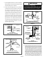
f−FAN OFF"
Fan OFF" timings (time that the blower operates after the
heat demand has been satisfied) are determined by the arrangement of a jumper on the VSP2−1 board. See figure 13.
To adjust fan OFF" timings, gently disconnect the jumper
and reposition it across pins corresponding with the new
timing. Fan OFF" time is adjustable from 90 to 330 seconds. The control has a non−adjustable, factory preset on"
fan timing (45 seconds).
WARNING − MAKE SURE TO DISCONNECT POWER
BEFORE CHANGING FAN OFF" TIMINGS.
FAN-OFF TIME ADJUSTMENT
TIMING
JUMPER
270
The TEST pin is available to bypass the VSP2−1 control and
run the motor at approximately 70% to test that the motor is
operational. This is beneficial primarily in troubleshooting. G must be energized for motor to run.
b−HEATING BLOWER"
150
For G32V units, place the HEATING BLOWER jumper
across the second and third pins (position #2).
To adjust fan−off timings:
Remove jumper from VSP2−1 and
select one of the other pin combinations to achieve the desired
time.
210
90
Leave jumper off to achieve
330 second fan−off timing.
TIMING PINS (seconds)
Fan-off timing is factory
set at 90 seconds
FIGURE 13
Page 16
in relation to specific modes of operation. Some information has been repeated from the previous section to provide
an example. Refer to each diagnostic LED or jumper settings
section for more information.
NOTEIf fan OFF" time is too low, residual heat in heat
exchanger may cause primary limit S10 to trip resulting
in frequent cycling of blower. If this occurs, adjust blower
to longer time setting.
Table 12 outlines the operation of the variable speed motor
TABLE 12
VSP2−1 G32V−1 / −3 units OPERATION
HEATING MODE
COOLING MODE
UNITS WITH
SINGLE−STAGE HEATING
UNITS WITH
TWO−STAGE HEATING
UNITS WITH SINGLE−SPEED
COMPRESSOR
UNITS WITH TWO−SPEED
COMPRESSOR
NON−ZONED
APPLICATIONS
NON−ZONED
APPLICATIONS
NON−ZONED
APPLICATIONS
NON−ZONED
APPLICATIONS
Using a single−stage thermostat with
one−stage" heating, the HEAT LED−
DS2 is lit when the thermostat calls for
heat. The ON/OFF LED−DS3 is lit after
110 seconds (65 seconds pre−purge
and 45 seconds fan ON" time) from
the time a call for heat is made. This indicates the blower is operating in heating speed.
Using a two−stage thermostat with first−
stage (W1) calling, the ON/OFF LED−
DS3 is lit to indicate the blower is operating in low speed.
The terminals DS and Y must be jumpered together. With a call for cooling,
terminals G, Y and DS on the unit control board are energized from the thermostat. HI/LOW LED−DS1 and ON/
OFF LED−DS3 are lit to indicate the
blower is operating on high speed.
The ON/OFF LED−DS3 is lit to indicate
the blower is operating in first stage
cooling. This LED is energized on
when a 24VAC thermostat demand is
supplied to the control (terminal G" on
the control board terminal strip).
In second stage, the ON/OFF LED−
DS3 and HI/LOW LED−DS1 are lit to indicate the blower is operating on high
speed (24VAC is supplied to the unit
terminal strip Y2 from Y2 on the thermostat).
NOTE Jumper must be moved from
Y1 to Y2 In two−speed, non−zoned applications.
Using a single−stage thermostat with
W2 TIMED," and W1 calling, the ON/
OFF LED−DS3 is lit to indicate the
blower is operating on low speed.
When the ON/OFF LED−DS3 and
HEAT LED−DS2 are lit, the blower is
operating in heating speed and second−stage (W2) heating is calling.
HEAT LED−DS2 is lit with a call for heat
from the thermostat. ON/OFF LED−
DS3 is lit after 110 seconds from the
time a call for heat is made.
When the HEAT LED−DS2 is lit, the
blower is operating in heating speed,
and second−stage (W2) heating is calling.
NOTEY and DS are factory jumpered for single−stage cooling, non−
zoned.
NOTEFor low speed during single−
stage cooling remove jumper from Y
and Ds.
HARMONY ZONED
APPLICATIONS
HARMONY ZONED
APPLICATIONS
HARMONY ZONED
APPLICATIONS
HARMONY ZONED
APPLICATIONS
The blower speed is controlled by the
PWM (pulse width modulation) signal
sent from the control center of the zoning system to the terminal strip’s DS
terminal. HI/LOW LED−DS1 and ON/
OFF LED−DS3 are lit to indicate the
blower is operating.
NOTE−In Harmony II zoning applications, HTG. BLOWER jumper must be
in position #2.
The blower speed is controlled by the
PWM (pulse width modulation) signal
sent from the control center of the zoning system to the terminal strip’s DS
terminal. HI/LOW LED−DS1 and ON/
OFF LED−DS3 are lit to indicate the
blower is operating.
The blower speed is controlled by the
PWM (pulse width modulation) signal
sent from the control center of the zoning system to the terminal strip’s DS
terminal. HI/LOW LED−DS1 and ON/
OFF LED−DS3 are lit to indicate the
blower is operating.
NOTE: For zone applications with Harmony, remove the wire from the pin #3 of the J73 terminal on the VSP control board, insulate the
end, and secure it to prevent from shorting.
Page 17
Diagnostic LEDs located on the VSP3−1 control board are provided to aid in identifying the unit’s mode of operation. Certain
scenarios will arise depending on the jumper positions. Refer
to figure 14 for identification.
7.VSP3−1 Blower Control Board (A24)
G32V−4 Units
G32V−4 units are equipped with a variable speed motor that
is capable of maintaining a specified CFM throughout the
external static range. The unit uses the VSP3−1 variable
speed control board, located in the blower compartment,
which controls the blower speed and provides diagnostic
LEDs. The control has both a non−adjustable, factory preset
ON" fan timing delay and an adjustable OFF" fan timing delay
(see figure 13).
IMPORTANT
The VSP3−1 also senses limit trip condition and turns on the
blower. The G32V limit switch is located in the middle of the
vestibule wall. When excess heat is sensed in the heat exchanger, the limit switch will open and interrupt the current
to the gas valve, while at the same time the VSP3−1 energizes
the blower on heating speed. The limit automatically resets
when the unit temperature returns to normal and the blower is
de−energized.
24 VAC half wave rectified (DC pulse), when measured with a meter, may appear as a lower or
higher voltage depending on the make of the meter. Rather than attempting to measure the output
voltage of A24, see G32V BLOWER & VSP3
BLOWER CONTROL BOARD TROUBLESHOOTING FLOW CHART in the TROUBLESHOOTING
section of this manual.
VSP3−1 VARIABLE SPEED CONTROL BOARD SELECTIONS
1
JP46
13 PIN PLUG
(BOARD TO MOTOR)
JP2
DELAY PROFILE
SELECTOR PINS
(COOLING ONLY)
DELAY
COOL SPEED
SELECTOR PINS
(COOLING, HEATING and
CONTINUOUS FAN)
COOL
1
HEAT
1
1
TEST
1
2
2
−
2
3
3
+
3
4
4
NORM
4
HTG.
BLOWER
HEATING STAGE
JUMPER SELECTOR PINS
ADJUST
2
HEATING SPEED
SELECTOR PINS
See table 13 for VSP3−1
factory settings
HEAT
DS3
HI/LOW
DS4
DS2
ON/OFF
DS1
CFM
DIAGNOSTIC
DS LEDS
90
270
210
JP73
15 PIN PLUG
(BOARD TO VARIOUS
POINTS IN FURNACE)
OPERATIONAL
SELECTOR PINS
(Affects both heating
and cooling modes)
150
JP1
FAN OFF"
TIMING PINS
1
FIGURE 14
Page 18
Diagnostic LED Lights
VSP3−1 BLOWER CONTROL BOARD (A24)
DS3 ON/OFF
1
ON/OFF−DS3 indicates there is a demand for the blower
motor to run. When the ON/OFF LED−DS3 is lit, a demand
is being sent to the motor. In heating mode only, there is a
45−second fan ON" delay in energizing ON/OFF LED−DS3.
Light will not go off until adjustable fan OFF" delay has expired.
J46
DELAY
COOL
1
2
3
4
HTG.
BLOWER
1
ADJUST
1
2
3
4
2
HEAT
TEST
−
+
NORM
1
2
3
4
HEAT
DS3
HI/LOW
DS4
DS2
ON/OFF
DS1
CFM
If ON/OFF LED−DS3 is on and both HIGH/LOW LED−DS1
& HEAT LED−DS2 are off, the motor will operate in low
speed (heating).
90
270
210
DS2 HEAT
If HEAT LED−DS2 is on, the blower is running in second−
stage heat speed according to the HEAT" jumper setting.
In heating mode only, there is a 45 second delay in energizing HEAT LED−DS2. Light will not go off until adjustable fan
OFF" delay has expired.
150
J73
1
J73
PIN 1 - C - 24 VAC common.
PIN 2 - G - Input signal from thermostat’s fan signal.
PIN 3 - W2 - Input signal for second stage heat from the thermostat.
PIN 4 - DS - Input signal for the blower speed regulation.
PIN 5 - Limit - Input signal from the external limit.
PIN 6 - R - 24 VAC power to the thermostat.
PIN 7 - C - 24 VAC common.
Pin 8 - C - 24 VAC common.
PIN 9 - CI - Input signal from the fan limit control.
PIN 10 - CO - Output signal to the burner control.
PIN 11 - HT - Input signal from the fan limit control.
PIN 12 - ACC - 24 VAC accessory output.
PIN 13 - 24V - Input 24 VAC power for the VSP2-1.
PIN 14 - 24V - Input 24 VAC power for the VSP2-1.
PIN 15 - V - Input signal from the gas line.
DS1 HI/LOW
HIGH/LOW LED−DS1 indicates the blower is operating in
the cooling mode.
DS4 CFM
CFM LED−DS4 indicates the CFM the blower is providing,
according to the jumper settings.
J46
PIN 1 - Not Used.
PIN 2 - C - 24 VAC common.
PIN 3 - C - 24 VAC common.
PIN 4 - Delay Tap - Delay profile programming input.
PIN 5 - Cool Tap - Cooling blower programming input.
PIN 6 - On / Off - On / off output signal to the ICM2 motor.
PIN 7 - Adjust Tap - ICM2 mode selection.
PIN 8 - NOT USED
PIN 9 - Hi / Low - Speed regulate input signal to the ICM2 motor with CCB1 and
HARMONY only
PIN 10 - Ref. V - ICM2 reference voltage.
PIN 11 - Heat Tap - Heating blower speed programming.
PIN 12 - C - 24 VAC common.
PIN 13 - cfm - Motor speed diagnostic signal.
Jumper Settings
IMPORTANT
Before changing jumper setting, make sure the
motor has completely stopped. Any jumper setting change will not take place while the motor
is running.
VOLTAGES INTO VSP3−1
To change jumper positions, gently pull the jumper off the pins
and place it on the desired set of pins. The following section
outlines the different jumper selections available and conditions associated with each one. Refer to figure 14 for identification.
Voltage across J73 pins 13 to 1 and 6 to 1 is 24VAC as shown here.
Refer to unit wiring diagram.
24VAC @ 60Hz.
34 volts
0
volts
−34 volts
Voltage across J73 pins 4 to 1 is approximately 15-20VDC (straight voltage)
if CCB is used. If Harmony is used a voltage of 0−25VDC should be present.
If CCB or Harmony is not used, pin 4 to 1 voltage is 21VAC.
After the CFM for each application has been determined, the
jumper settings must be adjusted to reflect those given in
VOLTAGES FROM VSP3−1 TO ELECTRONICALLY
CONTROLLED BLOWER MOTOR
Voltage across J46 pins 6 to 3 and 1 to 3 is half-rectified AC as shown here.
Refer to unit wiring diagram.
24VAC Half-Rectified (DC
Pulse)
Approx.
@ 60Hz.
34 volts
the tables on page 3 and 4. Using the tables, determine which
row of CFM volumes most closely matches the desired
CFM. Once a specific row has been chosen (NORMAL or
0
volts
Voltage across J46 pin 9 to 3 is approximately 15-20VDC if CCB is used. If CCB or
Harmony is not used, pin 9 to 3 voltage is approximately 21VAC. If Harmony is used
a voltage of 0−25VDC should be present.
FIGURE 15
−), CFM volumes from other rows cannot be used. Below
are the descriptions of each of the jumper selections. Refer to table 13 for factory settings. Refer to CFM tables for
approximate air volume for each setting.
Page 19
TABLE 13
VSP FACTORY SETTINGS FOR G32V−4 UNITS
MODEL
NUMBER
DELAY
COOL
ADJUST
HEAT
G32V3−75
4
4
NORM
3
G32V5−100
4
4
NORM
2
G32V5−125
4
4
"
4
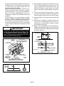
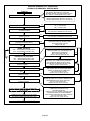
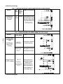
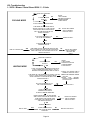
#1 PIN JUMPERED
A − Motor runs at 100% until demand is satisfied.
B − Once demand is met, motor ramps down to off.
A
B
100% CFM
OFF
NOTE − In Harmony II zoning applications in the heating mode, the
highest cooling speed selected is the highest blower speed obtainable. Also, the fan−only speed is used when the primary limit
has been tripped. In non−zoning applications, refer to the section
on the VSP3−1 control.
ADJUST
The ADJUST pins allow the motor to run at normal speed or
approximately 15% lower than normal speed. Blower
tables and the front of this manualgive two rows (NORMAL
and −) with their respective CFM volumes. The + adjustment setting is not operable. Notice that the normal adjustment setting for heat speed position #3 is 2030 CFM (955
L/s) in table 4. After the adjustment setting has been determined, choose the remainder speed jumper settings from
those in the table.
The TEST pin is available to bypass the VSP3−1 control and
run the motor at approximately 70% to test that the motor is
operational. This is beneficial primarily in troubleshooting. G
must be energized for motor to run.
HTG. BLOWER
For G32V−4 units only, place the HTG. BLOWER jumper
across the second and third pins (position #2).
NOTE − In Harmony II zoning applications, HTG. BLOWER
jumper must be in position #2.
HEAT
The HEAT jumper is used to set the blower speed to obtain
the required CFM as outlined in HEAT SPEED section of
tables 3 and 4.
The HEAT jumper selections are activated with a call for
first−stage heating (W1) and second−stage heating (W2).
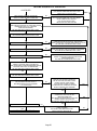
#2 PIN JUMPERED
A − Motor runs at 82% for approximately 7−1/2 minutes.
B − If demand has not been satisfied after 7−1/2 minutes,
the motor runs at 100% until demand is satisfied.
C − Once demand is met, motor ramps down to off.
Options 1, 2, 3, or 4 will have an increased dehumidification
effect on the system. Option 1 will have the least effect and
option 4 will have the greatest effect.
C
B
A
7 1/2 MIN
82%CFM
OFF
100% CFM
OFF
COOLING DEMAND
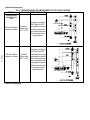
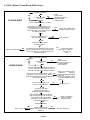
#3 PIN JUMPERED
A − Motor runs at 50% for 1/2 minute.
B − Motor then runs at 82% for approximately 7−1/2 minutes.
C − If demand has not been satisfied after 7−1/2 minutes,
motor runs at 100% until demand is satisfied.
D − Once demand is met, motor ramps down to off.
C
B
A
7 1/2 MIN
82% CFM
OFF
D
OFF
100% CFM
1/2 MIN
50% CFM
COOLING DEMAND
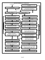
#4 PIN JUMPERED
A − Motor runs at 50% for 1/2 minute.
B − Motor then runs at 82% for approximately 7−1/2 minutes.
C − If demand has not been satisfied after 7−1/2 minutes,
motor runs at 100% until demand is satisfied.
D − Once demand is met, motor runs at 50% for 1/2 minute.
E − Motor ramps down to off.
C
B
A
OFF
7 1/2 MIN
82% CFM
1/2 MIN
50% CFM
D
E
100%
CFM
OFF
1/2 MIN
50% CFM
COOLING DEMAND
DELAY
The DELAY jumper is used to set the specific motor fan
mode of operation during cooling. Depending on the application, one of four fan options may be chosen by moving
the jumper to the appropriate set of pins.
OFF
COOLING
DEMAND
COOL
The cool jumper is used to set the blower speed to obtain
the required CFM as outlined in tables 3 and 4.
VSP Operation
Table 14 and 15 outline the operation of the variable speed
motor in relation to specific modes of operation. Some information has been repeated from the previous section to provide an example. Refer to each diagnostic LED or jumper
settings section for more information.
Page 20
TABLE 14
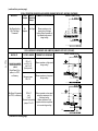
G32V−4 UNITS WITH CCB1, & TWO−SPEED OUTDOOR UNIT OPERATING SEQUENCE
Operating Sequence
System
Condition
System Demand
System Response
Step
Thermostat
Demand
*Relative Humidity
(EfficiencyPlus Lights)
***Compressor
Speed
Blower CFM
(COOL)
1
Y1
Acceptable (None)
Low
55% of
HIGH COOL
2
Y2
Acceptable (None)
High
HIGH COOL
1
Y1
Acceptable (None)
Low
55% of
HIGH COOL
2
Y1
Change to slightly
over setpoint (1)
Low
55% of
HIGH COOL
3
Demand
satisfied
Slightly over setpoint (1)
Off
Off
4
Y1
Slightly over setpoint (1)
High
**77%/74% of
HIGH COOL
1
Y1
Acceptable (None)
Low
55% of
HIGH COOL
2
Y1
Change to significantly
over setpoint (2 or more)
High
**77%/74% of
HIGH COOL
1
Y1
Over Setpoint
High
**77%/74% of
HIGH COOL
2
Y1
Change to Acceptable
(None)
High
3
None
Acceptable (None)
Off
Off
Normal operation
Call for humidity
removal during 1st
stage thermostat
demand
Significant increase
in humidity during
thermostat demand.
Humidity demand
satisfied during
thermostat demand.
Call for humidity
removal during 2nd
stage
g thermostat
demand
*Call
Call for 1st stage
cooling after call for
humidity removal.
Call for 2nd stage
cooling after call for
humidity removal
Call for cooling after
significant increase
in humidity
Humidity demand
satisfied between
thermostat demands
(unit off cycle).
HIGH COOL
4
Y1
Acceptable (None)
Low
55% of
HIGH COOL
1
Y2
Acceptable (None)
High
HIGH COOL
2
Y2
Change to slightly
over setpoint (1)
High
**77%/74% of
HIGH COOL
3
Y2
Acceptable (None)
High
HIGH COOL
1
None
Slightly over setpoint (1)
Off
Off
2
Y1
Slightly over setpoint (1)
Low
55% of
HIGH COOL
1
None
Slightly over setpoint (1)
Off
Off
2
Y2
Slightly over setpoint (1)
High
**77%/74% of
HIGH COOL
1
None
Significantly over setpoint
(2 or more)
Off
Off
2
Y1 or Y2
Significantly over
setpoint (2 or more
High
**77%/74% of
HIGH COOL
1
None
Over setpoint (1 or more)
Off
Off
2
Y1 or Y2
Change to
acceptable (None)
High
HIGH COOL
Comments
Compressor demand and indoor
blower speed follow thermostat
demand
Dehumidification mode begins with
next thermostat demand,
demand after initial
thermostat demand is satisfied.
If humidity increases significantly
over setpoint, or if slide switch is
moved significantly
significantly, unit will immediately go into dehumidification mode
(in presence of thermostat demand).
When humidity demand is satisfied,
blower immediately shifts to the
HIGH COOL CFM in order to hasten
the end of the cycle
cycle. Unit can only
g speed
p
p
shift out of high
compressor
operation
ti att b
beginning
i i off nextt cycle.
l
Blower immediately changes speed
in response to thermostat demand.
Dehumidification mode (high speed
compressor) begins with next therther
mostat demand after initial demand is
satisfied.
Reduced blower speed (dehumidification speed) begins immediately
with thermostat demand
If humidity increases significantly
over setpoint, or if slide switch is
moved unit immediately goes into
moved,
dehumidification mode (in presence
of thermostat demand).
While unit is not operating (no thermostat demand), slide switch is
moved down and back up. Blower
and compressor operate at high
speed until next thermostat demand.
Note − When changing unit mode of operation from cooling to heating, indicating lights that are on will stay on until the first thermostat heating demand.
*IMPORTANT - If power to unit is turned on with CCB1 calling for humidity removal, outdoor unit may be locked into high speed
indefinitely. To reset, move humidity slide switch all the way down then back up to desired setpoint (with unit running)
** Reduced blower speed is 77% of COOL for the V3 units; 74% of COOL for V5.
***If the two−speed control on a two−speed outdoor unit is set for LATCH 2 (15 minutes) or LATCH 3 (30 minutes), the compressor
will latch into high speed after a Y1 demand has occurred for that period of time.
Page 21
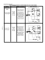
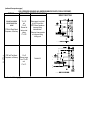
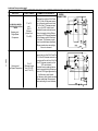
TABLE 15
G32V−4 Units with VSP3−1
Heating Mode
Cooling Mode
Units With
Single−Stage Heating
Units With
Two−Stage Heating
Units With
Single−speed Compressor
Non−Zoned Applications
Using a single−stage thermostat
with "one−stage" heating, the HEAT
LED−DS2 is lit when the thermostat
calls for heat. The ON/OFF LED−
DS3 is lit after 110 seconds (65 seconds prepurge and 45 seconds fan
"ON" time) from the time a call for
heat is made. This indicates the
blower is operating in high speed
heat.
Non−Zoned Applications
Using a two−stage thermostat with
first−stage (W1) calling, the ON/
OFF LED−DS3 is lit to indicate the
blower is operating in low speed
heat.
Non−Zoned Applications
Y1−DS and Y1−Y2 must be jumpered together. With a call for cooling, G, Y1, Y2 and DS on the unit
control board are energized from
the thermostat. HI/LOW LED−DS1
and ON/OFF LED−DS3 are lit to indicate a call for cooling.
Using a single−stage thermostat
with "W2 TIMED" and W1 calling,
the ON/OFF LED−DS3 is lit to indicate the blower is operating on low
speed heat.
When the ON/OFF LED−DS3 and
HEAT LED−DS2 are lit, the blower is
operating in high speed heat and
second−stage (W2) is calling.
HEAT LED−DS2 is lit with a call for
heat from the thermostat. ON/OFF
LED−DS3 is after 110 seconds from
the time a call for heat is made.
Note − Y1 to DS and Y1 to Y2 are
factory jumpered for single−stage
cooling, non−zoned applications.
Units With
Two−speed Compressor
Non−Zoned Applications
Y1−DS must be jumpered together.
With a call for single−stage cooling,
G, Y1, and DS on the unit control
board are energized from the Thermostat. With a call for second−stage
cooling, G, Y1, Y2, and DS on the
unit control board are energized
from the thermostat. In both cases,
HI/LOW LED−DS1 and ON/OFF
LED−DS3 are lit to indicate a call for
cooling.
Note − Jumper Y1−Y2 must be removed for units with two−speed
compressor.
When HEAT LED−DS2 is lit, the
blower is operating in high speed
heat and second−stage (W2) is calling.
Harmony Zoned Applications
The blower speed is controlled by
the PWM (pulse width modulation)
signal sent from the control center
of the zoning system to the terminal
strip’s DS terminal. HI/LOW LED−
DS1 and ON/OFF LED−DS3 are lit
to indicate the blower is operating.
Harmony Zoned Application
The blower speed is controlled by
the PWM (pulse width modulation)
signal sent from the control center
of the zoning system to the terminal
strip’s DS terminal. HI/LOW LED−
DS1 and ON/OFF LED−DS3 are lit
to indicate the blower is operating.
Note − In Harmony II zoning applications, HTG BLOWER jumper must
be in position #2.
Note − In Harmony II zoning applications, HTG BLOWER jumper must
be in position #2.
Harmony Zoned Application
The blower speed is controlled by
the PWM (pulse width modulation)
signal sent from the control center
of the zoning system to the terminal
strip’s DS terminal. HI/LOW LED−
DS1 and ON/OFF LED−DS3 are lit
to indicate the blower is operating.
Harmony Zoned Application
The blower speed is controlled by
the PWM (pulse width modulation)
signal sent from the control center
of the zoning system to the terminal
strip’s DS terminal. HI/LOW LED−
DS1 and ON/OFF LED−DS3 are lit
to indicate the blower is operating.
NOTE − For zone applications with Harmony, remove the wire from pin #2 and pin #13 of the J49 terminal at the motor and the wire
from pin #3 of the J73 terminal on the VSP control board, insulate the ends and secure to prevent shorting.
8.Two Stage Variable Speed Control (A24)
G32V−5 and later Units
WARNING
Shock hazard.
Disconnect power before servicing. Integrated
Control Board is not field repairable. If control is
inoperable, simply replace entire control.
Can cause injury or death. Unsafe operation will
result if repair is attempted.
G32V−5 and later units are equipped with the Lennox two−
stage, variable speed integrated SureLight control board.
The system consists of a ignition / blower control board
(figure 16 with control terminal designations in tables 16
through 19) and ignitor (figure 9). The board and ignitor
work in combination to ensure furnace ignition and ignitor
durability. The SureLight integrated board controls all major furnace operations. The board features two LED lights,
DS1 and DS2 for troubleshooting and four LED lights
(DS3, DS6, DS7 and DS8) to show furnace status. The
board also has two accessory terminals rated at (1) one
amp each. See table 20 for status code and table 21 for
troubleshooting diagnostic codes.
Electronic Ignition
At the beginning of the heat cycle the SureLight control
monitors the combustion air inducer prove switch. The control will not begin the heating cycle if the prove switch is
closed (by−passed). Once the prove switch is determined to
be open, the combustion air inducer is energized on low
(first stage) heat speed.
G32V−75 Only
At the beginning of the heat cycle the SureLight control
monitors the first and second stage combustion air inducer
prove switches. The control will not begin the heating cycle
if the first stage prove switch is closed (by−passed). Like
wise the control will not begin second stage heat if the second stage prove switch is closed and will allow first stage
heat only. However, if the second stage prove switch closes
DURING first stage pre−purge, the control will still respond
to second stage heat.
Page 22
Once the prove switch (first stage prove switch for
G32V−75) is determined to be open, the combustion air inducer is energized on low (first stage) heat speed. When
the differential in the prove switch is great enough, the
prove switch closes and a 15−second pre−purge begins. If
the switch is not proven within 2−1/2 minutes, the control
goes into Watchguard−Pressure Switch mode for a 5−minute re−set period. After the 15−second pre−purge period, the
SureLight ignitor warms up for 20 seconds after which the
gas valve opens for a 4−second trial for ignition. The ignitor
energizes during the trial until flame is sensed. If ignition is
not proved during the 4−second period, the control will try
four more times with an inter purge and warm−up time between trials of 35 seconds. After a total of five trials for ignition (including the initial trial), the control goes into Watchguard−Flame Failure mode. After a 60−minute reset period,
the control will begin the ignition sequence again.
The SureLight control board has an added feature that prolongs the life of the ignitor. After a successful ignition, the
SureLight control utilizes less power to energize the ignitor
on successive calls for heat. The control continues to ramp
down the voltage to the ignitor until it finds the lowest
amount of power that will provide a successful ignition. This
amount of power is used for 255 cycles. On the 256th call
for heat, the control will again ramp down until the lowest
power is determined and the cycle begins again.
Two Stage Operation / Thermostat Selection Jumper
The control can be utilized in two modes: SINGLE−STAGE
thermostat or TWO−STAGE thermostat. The thermostat
selection jumper E20, located just below dip switches 1
through 3 (figure 16), must be positioned for the particular
application. The jumper is factory set on TWO" for use with
a two−stage thermostat with two stage heat. Re−position
jumper to SINGLE" for use with a single stage thermostat
with two stage heat.
While in the single−stage thermostat mode (single jumper
setting), the burners will always fire on first−stage heat. The
combustion air inducer will operate on low speed and indoor blower will operate on low heat speed. After a 10 minute recognition period, the unit will switch to second stage
heat. While in the two−stage thermostat mode (two jumper
setting) the burners will fire on first−stage heat. The combustion air inducer will operate on low speed and indoor
blower will operate on low heat speed. The unit will switch
to second−stage heat on call from the indoor thermostat. If
there is a simultaneous call for first and second stage heat,
the unit will fire an first stage heat and switch to second
stage heat after 30 seconds of operation. See Sequence of
Operation flow charts in the back of this manual for more
detail.
Page 23
TW0−STAGE, VARIABLE SPEED INTEGRATED
CONTROL BOARD
DIAGNOSTIC
LEDs
DIP
SWITCHES
1−3
DIP
SWITCHES
5 − 12
LEDs
LED
ON−BOARD
JUMPER W951
ON−BOARD
ON−BOARD
(cut when heat pump is
JUMPER W914
JUMPER W915
used with FM21)
(cut when CCB1 or
Harmony II are used) (cut when two−stage
cooling is used)
THERMOSTAT CONNECTIONS (TB1)
DIP SWITCH FUNCTIONS
DIP SWITCH(ES)
FUNCTION
1 and 2
Blower Off Delay
3
Second Stage ON Delay (Single−stage t’stat)
4
Not used
5 and 6
Cooling Mode Blower Speed
7 and 8
Blower Speed Adjustment
9 and 10
Cooling Mode Blower Ramping Profile
11 and 12
Heating Mode Blower Speed
FIGURE 16
TABLE 16
TABLE 18
Two Stage Ignition / Blower Control Terminals
SureLight Board 12Pin Terminal Designation
LINE
Line 120VAC Neutral
PIN #
XFMR
Transformer 120VAC Neutral
1
Gas Valve High Fire
EAC
Electronic Air Cleaner 120VAC Neutral
2
Second Stage Prove Switch (G32V−75)
CIRC
Indoor Blower 120VAC Neutral
3
Not Used
HUM
Humidifier 120VAC Neutral
4
Ground
HUM
Humidifier 120VAC Hot
5
24V Hot
XMFR
Transformer 120VAC Hot
6
Primary Limit In
LINE
Line 120VAC Hot
7
Gas Valve Low Stage
CIRC
Indoor Blower 120VAC Hot
8
Gas Valve Common
EAC
Electronic Air Cleaner 120VAC Hot
9
24V Neutral
10
Ground
TABLE 17
SureLight Board 5 Pin Terminal Designation
Function
11
Primary Limit Out
12
1st Stage Prove Switch
PIN #
Function
1
Ignitor
TABLE 19
2
Combustion Air Inducer High Speed
SureLight Board 16 Pin Blower Control Terminals
3
Combustion Air Inducer Low Speed
4
Combustion Air Inducer Neutral
5
Ignitor Neutral
PIN #
Page 24
Function
1
Ground
2
Low Heat Speed
3
Ground
4
DELAY" Dip Switch Selection
5
COOL" Dip Switch Selection
6
Y1" Signal
7
ADJUST" Dip Switch Selection
8
Ground
9
0" From Thermostat
10
DS" Output Signal
11
HEAT" Dip Switch Selection
12
24 VAC
13
HIGH HEAT Speed
14
Y2" Signal
15
G"
16
CFM LED
TABLE 20
STATUS CODES
STATUS LED
COLOR
FUNCTION
DS3
ON / OFF ’
GREEN
DS3−ON indicates that the motor has a demand to operate. (This LED must be on in all
modes).
DS6
CFM"
GREEN
DS6−blinking indicates the airflow (CFM) demand in the motor. The air flow is determine by
counting blinks between two (2) second pauses. One blink equals roughly 100 CFM.
DS7
HI / LO"
YELLOW
DS7−ON indicaties the DS to R" jumper has not been cut. When the jumper is cut the system
will be operating with LENNOX HARMONY II (See Harmony Installation Instructions) or with
the CCB1 Efficiency Plus control.
CCB1: When ON, a 24 VAC is being applied and when OFF, it has been removed. This on/off
operation varies the indoor blower’s performance so dehumidification can be enhanced.
DS8
HEAT"
YELLOW
DS8−ON indicates the system is in HEAT mode.
TABLE 21
DIAGNOSTIC CODES
Diagnostic LEDs are labeled DS1 and DS2. See figure 16 for location of diagnostic LEDs.
DS1
DS2
SIMULTANEOUS
SLOW FLASH
SIMULTANEOUS
FAST FLASH
SIMULTANEOUS
SLOW FLASH
SIMULTANEOUS
FAST FLASH
DESCRIPTION
SLOW FLASH
ON
OFF
SLOW FLASH
OFF
FAST FLASH
High pressure switch open;
OR: Blocked inlet/exhaust vent;
OR: High pressure switch closed prior to activation of combustion air inducer.
ALTERNATING
SLOW FLASH
ALTERNATING
SLOW FLASH
Watchguard −− burners failed to ignite; OR limit open more than 3 minutes;
OR lost flame sense 5 times in one heating cycle;
OR pressure switch opened 5 times in one heating cycle.
SLOW FLASH
ON
ON
OFF
OFF
ON
OFF
ON
FAST FLASH
SLOW FLASH
SLOW FLASH
FAST FLASH
ALTERNATING
FAST FLASH
ALTERNATING
FAST FLASH
Power on − Normal operation.
Also signaled during cooling and continuous fan.
Normal operation − signaled when heating demand initiated at thermostat.
Primary, secondary or rollout limit switch open. Limits must close within 3 minutes
or unit goes into 1 hour Watchguard.
Low pressure switch open; (G32V−75 only)
OR: Blocked inlet/exhaust vent;
OR: Low pressure switch closed prior to activation of combustion air inducer.
Flame sensed without gas valve energized.
Circuit board failure or control wired incorrectly. Check 24 and 115 volts to board.
Main power polarity reversed. Switch line and neutral.
Low flame signal. Measures below 0.23 microAmps. Replace flame sense rod.
The following conditions are sensed during the ignitor warm−up period only:
1) Improper main ground;
2) Broken ignitor; OR: Open ignitor circuit;
3) Line voltage below 75 volts.
(If voltage lower than 75 volts prior to ignitor warm-up, control will signal waiting on
call from thermostat, and will not respond.
NOTE − Slow flash rate equals 1 Hz (one flash per second). Fast flash rate equals 3 Hz (three flashes per second).
Minimum flame sense current = 0.17−0.22 microAmps.
Page 25
Dip Switch Settings
Switches 1 and 2 −− Blower Off Delay −− The blower−on
delay of 45 seconds is not adjustable. The blower−off delay
(time that the blower operates after the heating demand
has been satisfied) can be adjusted by moving switches 1
and 2 on the integrated control board. The unit is shipped
from the factory with a blower−off delay of 90 seconds. The
blower off delay affects comfort and is adjustable to satisfy
individual applications. Adjust the blower off delay to
achieve a supply air temperature between 90° and 110°F at
the exact moment that the blower is de−energized. Longer
off delay settings provide lower supply air temperatures;
shorter settings provide higher supply air temperatures.The table below provides the blower off timings that will
result from different switch settings.
TABLE 22
Blower Off Delay Switch Settings
Blower Off Delay
Switch 1
Switch 2
(Seconds)
60
Off
Off
90
Off
On
120
On
Off
180
On
On
Switch 3 −− Second Stage Delay (Used with Single−
Stage Thermostat Only) −− This switch is used to determine the second stage on delay when a single−stage thermostat is being used. The switch is factory−set in the ON
position, which provides a 10−minute delay before second−
stage heat is initiated. If the switch is toggled to the OFF
position, it will provide a 15−minute delay before second−
stage heat is initiated. This switch is only activated when the
thermostat selector jumper is positioned for SINGLE−stage
thermostat use.
Switch 4 −− Not used.
Switches 5 and 6 −− Cooling Mode Blower Speed −−
Switches 5 and 6 are used to select cooling blower motor
speed. The unit is shipped from the factory with the dip
switches positioned for high speed (4) indoor blower motor
operation during the cooling mode. The table below provides the cooling mode blower speeds that will result from
different switch settings. Refer to blower data tables at the
front of this manual for corresponding cfm values.
TABLE 23
Cooling Mode Blower Speeds
Speed
Switch 5
Switch 6
1 − Low
On
On
2 − Medium Low
Off
On
3 − Medium High
On
Off
4 − High (Factory)
Off
Off
Switches 7 and 8 −− Blower Speed Adjustment −−
Switches 7 and 8 are used to select blower speed adjustment settings. The unit is shipped from the factory with the
dip switches positioned for NORMAL (no) adjustment. The
dip switches may be positioned to adjust the blower speed
by +10% or −10% to better suit the application. The table below provides blower speed adjustments that will result from
different switch settings. Refer to blower data tables at the
front of this manual for corresponding cfm values.
TABLE 24
Blower Speed Adjustment
Adjustment
Switch 7
Switch 8
+10% (approx.)
On
Off
NORMAL (Factory)
Off
Off
−10% (approx.)
Off
On
Switches 9 and 10 −− Cooling Mode Blower Speed
Ramping −− Switches 9 and 10 are used to select cooling
mode blower speed ramping options. Blower speed ramping may be used to enhance dehumidification performance.
The switches are factory set at option A which has the
greatest effect on blower motor performance. The table below provides the cooling mode blower speed ramping options that will result from different switch settings. The cooling mode blower speed ramping options are detailed on the
next page. See unit nameplate for manufacturing date.
TABLE 25
Cooling Mode Blower Speed Ramping
Ramping Option
Switch 9
Switch 10
A (Factory)
Off
Off
B
On
Off
C
Off
On
D*
On
On
*Only option for CCB1
Page 26
G32V units manufactured before April 2003
G32V units manufactured April 2003 and later
Ramping Option A (Factory Selection)
Motor runs at 50% for 1/2 minute.
Motor then runs at 82% for approximately 7−1/2 minutes.
If demand has not been satisfied after 7−1/2 minutes,
motor runs at 100% until demand is satisfied.
Once demand is met, motor runs at 50% for 1/2 minute.
Motor ramps down to off.
7−1/2 MIN
82% CFM
OFF
100%
CFM
1/2 MIN
50% CFM
OFF
S
S
S
S
S
Ramping Option A (Factory Selection)
Motor runs at 50% for 30 seconds.
Motor then runs at 82% for approximately 7−1/2 minutes. If demand has not been satisfied after 7−1/2 minutes.
Motor runs at 100% until demand is satisfied.
Once demand is met, motor runs at 50% for 30 seconds
then −
ramps down to stop.
7 1/2 MIN
82% CFM
OFF
1/2 MIN
50% CFM
1/2 MIN
50% CFM
COOLING DEMAND
S
S
S
Ramping Option B
Motor runs at 82% for approximately 7−1/2 minutes. If
demand has not been satisfied after 7−1/2 minutes −
motor runs at 100% until demand is satisfied.
Once demand is met, motor ramps down to stop.
7 1/2 MIN
82%CFM
OFF
7−1/2 MIN
82% CFM
OFF
1/2 MIN
50% CFM
COOLING DEMAND
Ramping Option B
Motor runs at 50% for 1/2 minute.
Motor then runs at 82% for approximately 7−1/2 minutes.
If demand has not been satisfied after 7−1/2 minutes,
motor runs at 100% until demand is satisfied.
Once demand is met, motor ramps down to off.
OFF
100%
CFM
100% CFM
100% CFM
OFF
COOLING DEMAND
OFF
1/2 MIN
50% CFM
COOLING DEMAND
Ramping Option C
Motor runs at 82% for approximately 7−1/2 minutes.
If demand has not been satisfied after 7−1/2 minutes,
the motor runs at 100% until demand is satisfied.
Once demand is met, motor ramps down to off.
S
Ramping Option C
Motor runs at 100% until demand is satisfied.
S
Once demand is met, motor runs at 100% for 60 seconds. Then,
S
ramps down to stop.
100% CFM
OFF
OFF
7−1/2 MIN
82%CFM
100% CFM
100% CFM
COOLING DEMAND
OFF
COOLING DEMAND
Ramping Option D
S− Motor runs at 100% until demand is satisfied.
Ramping Option D
Motor runs at 100% until demand is satisfied.
Once demand is met, motor ramps down to off.
OFF
100% CFM
COOLING
DEMAND
S− Once demand is met, motor ramps down to stop.
OFF
OFF
Page 27
100% CFM
COOLING
DEMAND
OFF
OFF
Switches 11 and 12 −− Heating Mode Blower Speed −−
Switches 11 and 12 are used to select heating mode blower
motor speed. The unit is shipped from the factory with the
dip switches positioned for medium low (2) speed indoor
blower motor operation during the heating mode. The table
below provides the heating mode blower speeds that will
result from different switch settings. Refer to blower data
tables at the front of this manual for corresponding cfm values.
TABLE 26
Heating Mode Blower Speeds
Speed
1 − Low
2 − Medium Low
(Factory)
3 − Medium High
4 − High
Switch 11
On
Switch 12
On
Off
On
On
Off
Off
Off
On−Board Jumper W914
On−board jumper W914, which connects terminals DS and
R on the integrated control board, must be cut when the furnace is installed with either the Harmony II zone control
board or the CCB1 EfficiencyPlus humidity control. Refer to
table 27 for operation sequence in applications including a
G32V, CCB1 and single−speed outdoor unit. Table 28 gives
the operation sequence in applications with a two−speed
outdoor unit.
On−Board Jumper W951
On−board jumper W951, which connects terminals R and O
on the integrated control board, must be cut when the furnace is installed in applications which include a heat pump
unit and the FM21 FuelMaster control board.
On−Board Jumper W915
On board jumper W915, which connects Y1 to Y2 terminals
on the integrated control board terminal strip must be cut if
two−stage cooling will be used.
On−Board Jumper W6
On board jumper W6 is an external measuring device for indoor blower CFM. If by chance W6 is cut, the CFM LED will
not operate but the furnace will operate as normal. The
jumper has no affect on furnace operation.
Diagnostic LEDs (DS1 and DS2)
Two diagnostic LEDs are located on the two−stage, variable
speed integrated control just to the left of the first bank of dip
switches. These lights’ flashes correspond with diagnostic
codes detailed on in table 21.
Status LEDs (HEAT, HI/LO, ON/OFF and CFM)
The integrated control includes four LEDs which indicate
operating status. The green ON/OFF LED is lit any time the
blower is operating. The green CFM LED indicates the
blower motor speed. Count the number of blinks between
the two−second pauses to determine the CFM. Each blink
represents approximately 100 CFM. The yellow HI/LO LED
is lit when the W914 (DS to R) jumper has not been clipped
for CCB1 or Harmony operation. The yellow HEAT LED is lit
when the indoor blower is operating at the HEATING
speed.
TABLE 27
G32V−5, CCB1 and Single−Speed Outdoor Unit
OPERATING MODE
SYSTEM DEMAND
SYSTEM RESPONSE
System Condition
Thermostat
Demand
*Relative Humidity
(EfficiencyPlus Lights)
Blower
CFM
(COOL)
Normal operation
Y1
COOL
Compressor demand and indoor blower
speed controlled by thermostat demand.
*Call for humidity
removal during
cooling demand
Y1
No demand. Humidity
level is acceptable
Humidity level rises
above setpoint. Demand
initiated.
77%/74%
of COOL
Call for dehumidification initiated by CCB1
control. Indoor blower speed reduced by
CCB1 control.
Dehumidification
demand satisfied
during cooling demand.
Y1
Humidity level falls below
setpoint. No demand
COOL
When humidity demand is satisfied, blower speed immediately increases to the
COOL CFM to hasten the end of the cycle.
Call for cooling after
call for humidity
removal.
None
Humidity level above setpoint. Demand initiated.
Off
Y1
Humidity level above setpoint. Demand initiated.
77%/74%
of COOL
Humidity demand
satisfied between
thermostat demands
(unit off cycle).
None
Over setpoint (1 or more)
Off
Y1
Change to acceptable
COOL
Comments
Dehumidification mode begins when rela
relative humidity is greater than setpoint.
While unit is not operating (no thermostat
demand) slide switch is moved down and
demand),
back up. Blower operates at COOL CFM.
NOTE − When changing unit mode of operation from cooling to heating, indicating lights that are on will stay on until the first thermostat heating demand.
* Reduced blower speed is 77% of COOL for V3 units and 74% of COOL for the V5 units.
Page 28
TABLE 28
G32V−5, CCB1 and Two−Speed Outdoor Unit
OPERATING MODE
System
Condition
Normal operation
Call for humidity
removal during
1st−stage cooling
demand
SYSTEM DEMAND
*Relative Humidity
(EfficiencyPlus Lights)
****Compressor
Speed
Blower CFM
(COOL)
Y1
No demand. Acceptable
Low
55% of
HIGH COOL
Y2
No demand. Acceptable
High
Y1
No demand. Acceptable
Low
HIGH COOL
55% of
HIGH COOL
Low
55% of
HIGH COOL
Off
Off
High
**77%/74% of
HIGH COOL
Low
55% of
HIGH COOL
High
**77%/74% of
HIGH COOL
High
**77%/74% of
HIGH COOL
Y1
Humidity level falls below
setpoint. No demand.
High
HIGH COOL
None
No demand. Acceptable
Off
Off
Y1
No demand. Acceptable
Low
55% of
HIGH COOL
Y2
No demand. Acceptable
High
HIGH COOL
High
**77%/74% of
HIGH COOL
High
HIGH COOL
Y1
Demand
satisfied
Y1
Significant increase in
humidity during
thermostat cooling
demand.
Y1
Y1
Y1
Humidity demand
satisfied during
thermostat demand.
Call for humidity
removal during 2nd
stage thermostat
demand
SYSTEM RESPONSE
Thermostat
Demand
Y2
Y2
Humidity level rises slightly
(1) above setpoint. Demand
initiated.
Humidity level remains
slightly (1) above setpoint.
Demand continues.
Humidity level remains
slightly (1) above setpoint.
Demand continues.
No demand. Acceptable
Humidity level rises significantly (2 or more) above
setpoint. Demand initiated.
Humidity level
above setpoint.
Humidity level rises slightly
(1) above setpoint. Demand
initiated.
No demand. Acceptable
*Call for 1st stage
cooling after call for
humidity removal.
None
Humidity level is slightly (1)
above setpoint.
Off
Off
Y1
Humidity level is slightly (1)
above setpoint.
Low
55% of
HIGH COOL
Call for 2nd stage
cooling after call for
humidity removal
None
Humidity level is slightly (1)
above setpoint.
Off
Off
Y2
Humidity level is slightly (1)
above setpoint.
High
**77%/74% of
HIGH COOL
Call for cooling after
significant increase in
humidity
None
Humidity level is significantly
above setpoint (2 or more).
Off
Off
Y1 or Y2
Humidity level is significantly
above setpoint (2 or more).
High
**77%/74% of
HIGH COOL
None
Humidity level is slightly (1)
above setpoint.
Off
Off
Y1 or Y2
Humidity level falls below
setpoint. No demand.
High
HIGH COOL
Humidity demand
satisfied between
thermostat demands
(unit off cycle).
Comments
Compressor demand and indoor
blower speed controlled by
thermostat demand
Dehumidification mode does not begin
until after initial thermostat demand is
satisfied and new cooling demand is
initiated.
If humidity rises significantly above setsignifipoint, or if slide switch is moved signifi
cantly,
l uniti will
ill immediately
i
di l go into
i
ded
humidification mode (in presence of
thermostat demand).
When humidity demand is satisfied,
blower immediately shifts to the COOL
CFM in order to hasten the end of the
cycle Unit can only shift out of high
cycle.
speed compressor operation at begin
beginning of next cycle.
Blower immediately changes speed in
response to thermostat demand.
Dehumidification mode (high speed
compressor) begins with next thermothermo
stat demand after initial demand is satisfied.
Reduced blower speed (dehumidification speed) begins immediately with
thermostat demand
If humidity increases significantly over
setpoint, or if slide switch is moved,
unit immediately goes into dehumidifidehumidifi
cation mode (in presence of thermostat
demand).
While unit is not operating (no thermostat demand), slide switch is moved
down and back up
up. Blower and com
compressor operate at high speed until
next thermostat demand.
Note − During mode of operation change from cooling to heating, indicating lights will not change until the first thermostat heating
demand.
*IMPORTANT - If power to unit is turned on with CCB1 calling for humidity removal, outdoor unit may be locked into high speed
indefinitely. To reset, move the humidity slide switch all the way down then back up to desired setpoint while the unit is running.
** Reduced blower speed is 77% of COOL for the V3 units; 74% of COOL for V5.
***If the two−speed control on a two−speed outdoor unit is set for LATCH 2 (15 minutes) or LATCH 3 (30 minutes), the compressor
will latch into high speed after a Y1 demand has occurred for that period of time.
Page 29
C−Blower Compartment (Figure 17)
G32V BLOWER MOTOR B3
J48
Located inside the blower compartment are the variable
speed blower motor (B3), coil choke (L13), and the secondary limit switches [(1)S21 and (2)S21]. To access the blower compartment follow the steps outlined below:
SHAFT
1. Blower Motor (B3)
MOTOR
G32V units use a three-phase, electronically controlled D.C.
brushless motor (controller converts single phase a.c. to three
phase D.C.), with a permanent-magnet-type rotor (figure 18).
Because this motor has a permanent magnet rotor it does not
need brushes like conventional D.C. motors. Internal components are shown in figure 19. The stator windings are split into
three poles which are electrically connected to the controller.
This arrangement allows motor windings to turn on and off
in sequence by the controller.
J49
CONTROLLER
FIGURE 18
G32V BLOWER MOTOR COMPONENTS
STATOR
(WINDINGS)
BEARING
OUTPUT
SHAFT
SUPPLY AIR BLOWER
AND SECONDARY LIMITS
ROTOR
FIGURE 19
A solid-state controller is permanently attached to the
motor. The controller is primarily an A.C. to D.C. converter. Converted D.C. power is used to drive the motor. The
controller contains a microprocessor which monitors
varying conditions inside the motor (such as motor workload).
The controller uses sensing devices to sense what position
the rotor is in at any given time. By sensing the position of the
rotor and then switching the motor windings on and off in sequence, the rotor shaft turns the blower.
BLOWER
BLOWER
COIL
WHEEL
MOTOR (B6)
CHOKE
(L13)
To Remove Blower From Unit: Remove Bolts and
Wiring Jackplugs. Then Slide Out Front of Unit.
G32V series blower motor ratings are listed in table 29.
All G32V blower motors use single phase power. An external run capacitor is not used. The motor uses permanently lubricated ball-type bearings.
FIGURE 17
3 3
To Remove Blower:
1. Turn off line voltage power. Unplug J69
from P69 located on blower deck.
2. Disconnect thermostat wiring connections at the terminal strip.
3. Disconnect J58/P58 and located on blower deck.
4. Disconnect J43/P43 and J49/P49 from
blower motor.
5. Disconnect wires from power choke.
6. Remove screw from control panel bracket at the blower.
7. Loosen screws (2) and remove control
box assembly from unit. Holes are slotted
so screws do not need to be removed.
8. Remove screws (2) and remove blower
from unit.
1
7
8
4 4
7
FIGURE 20
Page 30
2
5
6
TABLE 29
ELECTRONICALLY CONTROLLED BLOWER MOTOR
CCW ROTATION
Unit
Volts
Phase
HP
G32V3
G32V5
120
1
1/2
120
1
1
Internal Operation
Each time the controller switches a stator winding (figure 19)
on and off, it is called a pulse." The length of time each pulse
stays on is called the pulse width." By varying the pulse width
(figure 21), the controller varies motor speed (called pulsewidth modulation"). This allows for precise control of motor
speed and allows the motor to compensate for varying load
conditions as sensed by the controller. In this case, the controller monitors the static workload on the motor and varies motor
rpm in order to maintain constant airflow (cfm).
The motor is equipped with 11 incremental taps which are driven by the integral controller. The controller is capable of controlling three of the 11 taps.
The motor controller is driven by the VSP2−1, VSP3−1 or
two−stage variable speed SureLight control. The control
receives its demand (PWM signal or fixed 24 VAC or VDC
signal) from optional controls such as the Harmony zone control system, Efficiency Plus Humidity Control (CCB1) or a conventional thermostat.
Motor rpm is continually adjusted internally to maintain
constant static pressure against the blower wheel. The controller monitors the static work load on the motor and motor ampdraw to determine the amount of rpm adjustment. Blower rpm
may be adjusted any amount in order to maintain a constant
cfm as shown in Blower Ratings Tables. The amount of adjustment is determined by the incremental taps which are used
and the amount of motor loading sensed internally. The cfm remains relatively stable over a broad range of static pressure.
Since the blower constantly adjusts rpm to maintain a specified
cfm, motor rpm is not rated. Hence, the terms blower speed"
and speed tap" in this manual, on the unit wiring diagram and
on blower B3 refer to blower cfm regardless of motor rpm.
Page 31
When Harmony is used, speed taps are overridden and a
PWM signal generated by the Harmony controller continuously
varies motor speed based upon zone demands.
Initial Power Up
When line voltage is applied to B3, there will be a large inrush
of power lasting less than 1/4 second. This inrush charges a
bank of DC filter capacitors inside the controller. If the disconnect switch is bounced when the disconnect is closed, the disconnect contacts may become welded. Try not to bounce the
disconnect switch when applying power to the unit.
Motor Start-Up
When B3 begins start-up, the motor gently vibrates back and
forth for a moment. This is normal. During this time the electronic controller is determining the exact position of the rotor.
Once the motor begins turning, the controller slowly eases the
motor up to speed (this is called soft-start"). The motor may
take as long as 10-15 seconds to reach full speed. If the motor
does not reach 200rpm within 13 seconds, the motor shuts
down. Then the motor will immediately attempt a restart. The
shutdown feature provides protection in case of a frozen bearing or blocked blower wheel. The motor may attempt to start
eight times. If the motor does not start after the eighth try, the
controller locks out. Reset controller by momentarily turning off
power to unit.
The DC filter capacitors inside the controller are connected
electrically to the speed tap wires. The capacitors take
approximately 5 minutes to discharge when the disconnect
is opened. For this reason it is necessary to wait at least 5
minutes after turning off power to the unit before attempting to change speed taps.
DANGER
Disconnect power from unit and
wait at least five minutes to allow
capacitors to discharge before attempting to adjust motor speed tap
settings. Failure to wait may cause
personal injury or death.
MOTOR SPEED CONTROL WITH D.C. PULSE-WIDTH MODULATION
Motor speed is determined by the size of the electrical pulse sent to
the motor windings. The longer the pulse, the faster the motor.
OUTPUT FROM CONTROLLER TO MOTOR WINDINGS
WINDINGS TURNED OFF
WINDINGS TURNED ON
ÇÇ
ÇÇ
ON PULSE
ÇÇ
ÇÇ
OFF PULSE
The frequency of the pulses to the windings is 20KHz.
DO NOT ATTEMPT TO MEASURE THESE VOLTAGES.
LOW SPEED HEAT/COOL (output from controller to motor windings)
One
Pulse
One revolution
325VDC
O volts
WINDING #1
325VDC
O volts
WINDING #2
325VDC
O volts
WINDING #3
ÇÇÇÇÇÇÇÇÇÇÇÇÇÇÇÇÇÇ
ÇÇÇÇÇÇÇÇÇÇÇÇÇÇÇÇÇÇ
ÇÇÇÇÇÇÇÇÇÇÇÇÇÇÇÇÇÇ
ÇÇÇÇÇÇÇÇÇÇÇÇÇÇÇÇÇÇ
ÇÇÇÇÇÇÇÇÇÇÇÇÇÇÇÇÇÇ
ÇÇÇÇÇÇÇÇÇÇÇÇÇÇÇÇÇÇ
HIGH SPEED HEAT (output from controller to motor windings)
One revolution
325VDC
O volts
WINDING #1
325VDC
O volts
WINDING #2
325VDC
O volts
WINDING #3
ÇÇÇÇÇÇÇÇÇÇÇÇÇÇÇÇÇÇ
ÇÇÇÇÇÇÇÇÇÇÇÇÇÇÇÇÇÇ
ÇÇÇÇÇÇÇÇÇÇÇÇÇÇÇÇÇÇ
ÇÇÇÇÇÇÇÇÇÇÇÇÇÇÇÇÇÇ
ÇÇÇÇÇÇÇÇÇÇÇÇÇÇÇÇÇÇ
ÇÇÇÇÇÇÇÇÇÇÇÇÇÇÇÇÇÇ
HIGH SPEED COOL (output from controller to motor windings)
325VDC
O volts
ÇÇÇÇÇÇÇÇÇÇÇÇÇÇÇÇÇ
ÇÇÇÇÇÇÇÇÇÇÇÇÇÇÇÇÇ
ÇÇÇÇÇÇÇÇÇÇÇÇÇÇÇÇÇ
ÇÇÇÇÇÇÇÇÇÇÇÇÇÇÇÇÇ
ÇÇÇÇÇÇÇÇÇÇÇÇÇÇÇÇÇ
ÇÇÇÇÇÇÇÇÇÇÇÇÇÇÇÇÇ
One revolution
WINDING #1
325VDC
O volts
325VDC
O volts
WINDING #2
WINDING #3
FIGURE 21
Page 32
External Operation (Speed Tap Priority)
Figure 22 shows the two quick-connect jacks (J48 and J49)
which connect the motor to the G32V. Jack J48 is the power
plug and jack J49 connects the unit controls to the motor.
Line voltage must be applied to J48 pin 5 in order for the motor to operate. When using 120VAC pins 1 and 2 must be
jumpered. When control voltage is applied to J49 pin 3 and
15 (single stage heating and cooling), the motor is energized on the low speed heat/cool tap.
When voltage is applied to J49 pin 2 in addition to pin 3 and
15 (second stage heating), the blower is energized on the
high speed heating tap. When voltage is applied to J49 pin
10 in addition to pin 3 and 15 (second stage cooling), the
blower is energized on the high speed cooling tap. The motor
assigns priority to J49 pin 2 so that if a call for cooling and a call
for heating are concurrent, heating call overrides and the blower operates on high speed heating tap.
ICM2 with VSP3 and Two Stage Variable Speed
Control
The ICM2 operates slightly different than stated above
when matched with the VSP3 control. When control voltage
is applied to J49 pin 3 and 15, the motor is energized on
continuous fan. When voltage is applied to J49 pin 2 in
addition to pin 3 and 15 (first stage heating), the blower is
energized on the low speed heating tap. When voltage is
applied to J49 pin 13 in addition to pin 3 and 15 (second
stage heating), the blower is energized on the high speed
heating tap. The motor assigns priority to J49 pin 2 so that if
a call for cooling and a call for heating are concurrent, heating call overrides and the blower operates on high speed
heating tap.
BLOWER B3 HARNESS CONNECTORS
POWER
CONNECTOR J48
J49
CONTROL
PIN 1 - C1
CONNECTOR J49
PIN 2 - W / W1
PIN 3 - C2
PIN 4 − Delay
1 PIN 5 - Cool
PIN 6 - Y1
PIN 7 - Adjust
PIN 8 - 0ut
PIN 9 - 0
PIN 10 - BK / PWM
PIN 11 - Heat
PIN 12 - R
PIN 13 - EM / W2
PIN 14 - Y / Y2
PIN 15 - G
PIN 16 - Out +
J48
PIN 1 - Jumper PIN 1 to PIN2 for 120VAC line input only.
PIN 2 - Jumper PIN 1 to PIN2 for 120VAC line input only.
PIN 3 - Ground
PIN 4 - AC Line
PIN 5 - AC Line
FIGURE 22
Page 33
DANGER
Do not attempt to repair electronically controlled
blower motor or VSP. There are no field serviceable
parts. If either component appears to be faulty after
following checkout procedure, replace entire component then recheck for proper operation.
2−Choke Coil (L13)
A choke coil is used on all G32V units. The choke is located on the blower housing and is used to block radio frequency interference.
Precautions
If the G32V or its electronically controlled blower motor is improperly or inadequately grounded, it may cause television interference (commonly known as RFI or radio frequency interference).
This interference is caused by internal switching frequencies of the motor controller. TV interference may
show up as small specks or lines which randomly appear
on the TV screen accompanied by pops or clicks in the sound.
Before attempting any service, make sure the indoor unit is
causing the interference. To check, disconnect power to indoor
unit then check TV for continued signs of interference.
TV interference may be stopped by making sure the motor is solidly grounded to the cabinet (metal to metal) and
by making sure the cabinet is solidly grounded. If TV interference persists, make sure the television (and all affected
RF appliances) are moved away from the G32V. Also make
sure affected appliances are connected to a separate electrical
circuit.
SENSOR
LIMIT CONTROL (S10) FOR
G32V SERIES UNITS AND ALTERNATE STYLE
Units may be equipped with either style limit.
LIMIT
A flame sensor is located on the left side of the burner support. See figure 23. The sensor is mounted on a bracket in
the burner support and the tip protrudes into the flame envelope of the left−most burner. The sensor is fastened to
burner supports and can be removed for service without removing any part of the burners. During operation, flame is
sensed by current passed through the flame and sensing
electrode. The SureLight control allows the gas valve to remain open as long as flame signal is sensed.
SPADE CONNECTORS
D−Heating Components
1.Flame Sensor
INSULATING COVER (s)
FIGURE 24
4.Flame Rollout Switch (S47)
Flame rollout switch S47 is a SPST N.C. high temperature limit
located on the right side of the burner box assembly (see figure
IGNITOR
3/8"
25). S47 is wired to the burner ignition control A92. When
S47 senses flame rollout (indicating a blockage in the
combustion passages), the flame rollout switch trips,
and the ignition control immediately closes the gas
valve. Switch S47 in all G32V units is factory preset to open
at 200F + 12F (93C + 6.7C) on a temperature rise. All
flame rollout switches are manually reset.
FLAME ROLLOUT SWITCH (S47)
FLAME ROLLOUT
SWITCH (S47)
FIGURE 23
NOTE − The G32V furnace contains electronic components that are polarity sensitive. Make sure that the furnace is wired correctly and is properly grounded.
FIGURE 25
2.Combustion Air Inducer (B6)
All G32V units use a two−stage combustion air inducer to move
air through the burners and heat exchanger during heating operation. The blower uses a 120VAC motor. The motor operates
during all heating operation and is controlled by the SureLight
integrated control A92 and the two−stage control board A86.
The combustion air inducer operates for 15 seconds before
burner ignition (pre-purge) and for 5 seconds after the gas
valve closes (post-purge). The combustion air inducer operates on low speed during first−stage heat (low fire), then
switches to high speed for second−stage heat (high fire).
3.Primary Limit Control (S10) Figure 24
The primary limit (S10) on G32V units is located in the
middle of the heating vestibule panel. When excess heat is
sensed in the heat exchanger, the limit will open. If the limit
is tripped, the furnace control energizes the supply air blower and de−energizes the gas valve. The limit automatically
resets when unit temperature returns to normal. The switch
is factory set and cannot be adjusted. The switch may
have a different setpoint for each unit model number.
However, the setpoint will be printed on the outside face
of the limit.
5.Burners
All units use inshot burners (see figure 26). Burners are factory
set and do not require adjustment. A sight glass is furnished
in the burner box assembly for flame viewing. Always operate the unit with the burner box cover in place. Burners
can be removed as an assembly for service. Burner maintenance and service is detailed in the MAINTENANCE section
of this manual. Each burner uses an orifice which is precisely
matched to the burner input (see nameplate for orifice size).
The orifice is threaded into the burner manifold. The burner
is supported by the orifice and will easily slide off for service.
Each orifice and burner are sized specifically to the unit. Refer to Lennox Repair Parts Listing for correct sizing information. A flame retention ring in the end of each burner maintains
correct flame length and shape and keeps the flame from lifting
off the burner head. In addition, the burner entrance to each
clamshell (Figure 2) is fitted with a corbel cup (orifice) used to
direct the flow of comTYPICAL BURNER ASSEMBLY
bustion products.
FIGURE 26
Page 34
6.Gas Valve
WHITE RODGERS 36E SERIES GAS VALVE
PROPANE GAS
The G32V uses gas valves manufactured by White Rodgers or Honeywell. The valves are two-stage internally redundant to assure safety shut−off. If the gas valve must be
replaced, the same type valve must be used. The Honeywell valve (figure 27) is adjustable on low fire and high fire
and is field convertible for LP. WhiteRodgers supplies two
separate valves for natural and LP (figures 28 and 29) .
White Rodgers valves are not adjustable on low fire.
HI
the SureLight integrated control and the two−stage control. 24V
applied to the terminals energizes the valve.
IMPORTANT
WhiteRodgers valve is NOT adjustable on low
fire. Do not attempt to adjust low fire on WhiteRodgers valve.
HONEYWELL VR8205 Series Gas Valve
MANIFOLD
PRESSURE
TAP
HIGH FIRE
ADJUSTMENT
SCREW
(under cap)
P M
C
MANIFOLD
PRESSURE
OUTLET ON
SIDE
FIGURE 29
24VAC terminals and gas control knob are located on top of the
valve. Terminals on the gas valve are connected to wires from
HIGH HEAT
MANIFOLD
PRESSURE
ADJUSTMENT
ON SIDE
(under cap)
100% Sealed Combustion
The burner box is completely sealed and operates under a
negative pressure. A pressure hose is connected from the
burner box to the gas valve regulator and differential pressure switch. The gas valve senses the pressure in the burner box and changes gas valve output based on changes in
burner box pressure. The intent is to compensate for different vent configurations which can greatly affect the rate of
the unit.
Figure 30 show how gas valve output changes as burner
box pressure changes. Generally, a lower burner box
pressure produces a leaner gas/air mixture and a higher
burner box pressure produces a richer mixture. Burner
box pressure pressure will be between 0" and −1.0". Manifold pressure for natural units should be 3.5" W.C. + or −
.30" and 7.0" W.C. + or − .30" for propane units. A procedure showing how to check manifold pressure is shown on
page 32.
NORMAL OPERATION
lOW FIRE
ADJUSTMENT
SCREW
(under cap)
GAS VALVE SHOWN IN OFF POSITION
INLET PRESSURE TAP
FIGURE 27
WHITE RODGERS 36E SERIES GAS VALVE
NATURAL GAS
HIGH HEAT
MANIFOLD
PRESSURE
ADJUSTMENT
ON SIDE
(under cap)
GAS VALVE OUTPUT
MANIFOLD PRESSURE (positive inches water column)
3.5
3.4
OPERATION AT THIS EXTREME
MAY INDICATE A BLOCKED
INLET OR OTHER PROBLEM"
3.3
3.2
3.1
3.0
2.9
2.8
2.7
AOPERATION AT THIS EXTREME
MAY INDICATE A BLOCKED
OUTLET OR OTHER PROBLEM
2.6
2.5
−1.0
MANIFOLD
PRESSURE
OUTLET ON
SIDE
FIGURE 28
−0.8
−0.6
−0.2
Gray area indicates normal operating range + 10% of manifold pressure.The purpose of this chart is to explain unit operation . Each unit
may vary depending on installation, altitude, intake/exhaust configuration and other factors.
FIGURE 30
Page 35
−0.4
BURNER BOX PRESSURE
(Negative inches water gauge
measured on right side of burner box)
0
7.Differential Pressure Switch (S102) all
units, (S128) G32V−75 units only
(Combustion Air Prove Switch)
All G32V series units are equipped with a proving switch
S102 located on the vestibule panel.The G32V−75 unit only,
is equipped with a second prove switch S128. The switches
are connected to the combustion air inducer housing by
means of a flexible silicon hose. A separate hose connects
the prove switch to the burner box and the gas valve regulator. The silicon hose on S128 will tee into S102. See figure31. The switch monitors air pressure in the combustion
air inducer housing and burner box.
Both switches are a single-pole single-throw normally open
pressure switch electrically connected in series with the ignition control. The purpose of the switch is to prevent burner
operation if the combustion air inducer is not operating. The
switch also guards against insufficient combustion air, due to
restrictions in the intake and exhaust piping.
On start-up, the switch senses that the combustion air inducer is operating. It closes a circuit to the ignition control when
the difference in pressure across the prove switch increases
above a particular setting. See table 30. The pressure
sensed by the switch is relative to the pressure in the burner
box. In order for the furnace to operate, the larger negative must always be on the combustion air inducer side
of the switch. If the flue or air inlet become obstructed during operation, the switch senses a loss of pressure differential (drops below set point) and opens the circuit to the ignition control.
The switch is factory set and is not adjustable. It is a safety
shut-down control and MUST not be bypassed.
Figure 32 shows an example of the pressure differential
(.25" W.C.. shown) required to obtain unit operation. If the
switch does not successfully sense the required differential, the switch cannot close and the furnace cannot operate.
When measuring the pressure differential, readings should
be taken at the prove switch.
G32V
model
TABLE 30
Pressure Pressure Switch Setting
Switch
in. negative W.C..
S102
.40 $ .05
S128
.20 $ .05
100,000
btuh
S102
.25 $ .05
125,000
btuh
S102
.20 $ .05
75,000
btuh
DIFFERENTIAL PRESSURE SWITCH CIRCUITRY
(G32V3−75 SHOWN)
BURNER
TEE
BOX
HOSE
BARB
S102 PROVE
SWITCH
BURNER
BOX
SENSING
HOSE
TEE
GAS
VALVE
SENSING
HOSE
S128 PROVE
SWITCH
(G32V3−75
ONLY)
COMBUSTION
AIR BLOWER
GAS
VALVE
PRESSURE SWITCH
HOSE
FIGURE 31
Page 36
CHART REPESENTS NORMAL OPERATING
CHARACTERISTICS OF THE PRESSURE SWITCH ONLY
AND SHOULD NOT BE USED FOR TROUBLSHOOTING
COMBUSTION AIR BLOWER STATIC PRESSURE
−1.2
DIFFERENTIAL SWITCH CLOSED
−1.0
−0.8
−0.6
DIFFERENTIAL SWITCH OPEN
(Furnace will not operate)
−0.4
−0.2
0
0
−0.2
−0.4
−0.6
−0.8
−1.0
−1.2
BURNER BOX STATIC PRESSURE
FIGURE 32
Temporarily jumpering the pressure switch when troubleshooting will determine if the pressure switch and furnace
are operating properly. However, this may not indicate if the
sealed combustion system is operating properly. If the unit
cannot attain the required inches differential (see table 30) ,
the unit will not operate. Be sure to remove jumper when finished. See Warning this page.
Measuring pressure differential
The differential pressure is the difference in pressure measured on either side of the pressure switch:
1 − Remove thermostat demand and allow to cycle off.
2 − Disconnect hose from left side of pressure switch and
install Tee as shown in figure 33.
TEE AND 1/4"i.d. RUBBER HOSE FIELD PROVIDED
USED FOR MEASURING PRESSURE
ACROSS BURNER BOX AND COMBUSTION AIR BLOWER
WARNING
Safety Hazard. Turn off gas supply before jumpering switch or testing switch differential. If
switch is operating properly and sealed combustion system is operating improperly, a potentially lethal situation will be created when
switch is bypassed. DO NOT ALLOW UNIT TO
OPERATE WITH SAFETY SYSTEMS BYPASSED.
Checks of pressure differential can be made as an aid in troubleshooting. It is important to remember that the switch must
see the required differential in order for the furnace to operate.
Lack of differential usually indicates problems in the intake or
exhaust piping but may indicate problems in the heat exchanger, condenser coil, header boxes, combustion blower or other
components. Generally, if both readings are closer to zero (figure 32) the unit may have a restricted flue outlet or other problem. If both readings are farther from zero (figure 32) the unit
may have a restricted flue inlet or other problem.
Page 37
TO PRESSURE
SENSING HOSE
TO PRESSURE
SWITCH
TO DRAFT GAUGE
FIGURE 33
3 − Install draft gauge to open end of Tee.
4 − Operate unit and observe draft gauge reading. Readings will change as heat exchanger warms.
a. Take one reading immediately after startup.
b. Take a second reading after unit has reached steady
state (approximately 5 minutes).
5 − Remove thermostat demand and allow to cycle off.
6 − Remove draft gauge and Tee. Reinstall combustion air
sensing hose to left side of pressure switch.
7 − Disconnect hose from right side of pressure switch and
install Tee as shown in figure 33.
8 − Install draft gauge to open end of Tee.
9 − Operate unit and observe draft gauge reading. Readings will change as heat exchanger warms.
a. Take one reading immediately after startup.
b. Take a second reading after unit has reached steady
state (approximately 5 minutes). Both readings should
fall above the line shown in figure 32.
10− Compare readings to figure 32. Be sure to compare
only like readings (compare startup reading to startup
reading, then compare steady state reading to steady
state reading). Subtract the absolute steady state readings from one another. This will be the pressure differential. In order for the furnace to operate, the larger
negative must always be on the combustion air
blower side of the switch.
Example − one side of the pressure switch reads .60"
and the other side of the pressure switch reads .10".
Pressure differential is .60" − .10"= .50"
The pressure differential should be greater
than the settings in table 30.
11− When test is complete, remove thermostat demand
and allow unit to cycle off.
12− Remove draft gauge and Tee. Reinstall pressure
switch sensing hose to left side of pressure switch.
If pressure switch does not close at start up or differential is
less than set point the following should be checked.
1 − Restriction in exhaust and or intake vent.
2 − Pressure switch lines are routed correctly and for damage.
3 − Condensate in pressure switch lines.
4 − Wiring of pressure switch to furnace.
5 − Blocked heat exchanger or leak in heat exchanger.
II−PLACEMENT AND INSTALLATION
Make sure unit is installed in accordance with installation instructions and applicable codes.
6 − Promptly apply solvent cement to end of pipe and inside socket surface of fitting. Cement should be applied lightly but uniformly to inside of socket. Take care
to keep excess cement out of socket. Apply second
coat to end of pipe.
NOTE−Time is critical at this stage. Do not allow primer
to dry before applying cement.
7 − Immediately after applying last coat of cement to pipe,
and while both inside socket surface and end of pipe
are wet with cement, forcefully insert end of pipe into
socket until it bottoms out. Turn pipe 1/4 turn during assembly (but not after pipe is fully inserted) to distribute
cement evenly. Once joint is made, PVC may swell.
Hold joint together until bonded (approximately 20 seconds).
NOTE−Assembly should be completed within 20 seconds after last application of cement. Hammer blows
should not be used when inserting pipe.
8 − After assembly, wipe excess cement from pipe at end
of fitting socket. A properly made joint will show a bead
around its entire perimeter. Any gaps may indicate a
defective assembly due to insufficient solvent.
9 − Handle joints carefully and support properly until completely set.
B−Venting Considerations
The thickness of construction through which vent/air intake
pipes may be installed is 24" (610mm) maximum and 3"
(76mm) minimum. If a G32V furnace replaces a furnace
which was commonly vented with another gas appliance, the
size of the existing vent pipe for that gas appliance must be
checked. Without the heat of the original furnace flue products, the existing vent pipe may be oversized for the single
water heater or other appliance. The vent should be checked
for proper draw with the remaining appliance.
A−PVC Joint Cementing Procedure
WARNING
DANGER OF EXPLOSION! Fumes from PVC glue
may ignite during system check. Remove spark
plug wire from ignition control before 120V power
is applied. Reconnect wire after two minutes.
1 − Measure and cut vent pipe to desired length.
2 − Debur and chamfer end of pipe, removing any ridges or
rough edges. If end is not chamfered, edge of pipe may
remove cement from fitting socket and result in a leaking joint.
3 − Clean and dry surfaces to be joined.
4 − Test fit joint and mark depth of fitting on outside of
pipe.
5 − Uniformly apply liberal coat of PVC primer for PVC or
ABS cleaner for ABS for at least 5 to 15 seconds to inside
socket surface of fitting and male end of pipe to depth of
fitting socket. Remove puddles of primer before applying
cement.
CAUTION
Insufficient combustion air can cause headaches, nausea, dizziness or asphyxiation. Excessive exposure to contaminated combustion air
will result in safety and performance related
problems. Avoid exposure to the following substances in the combustion air supply:
Permanent wave solutions;
Chlorinated waxes and cleaners;
Chlorine base swimming pool chemicals;
Water softening chemicals;
De−icing salts or chemicals;
Carbon tetrachloride;
Halogen type refrigerants;
Cleaning solvents (such as perchloroethylene);
Printing inks, paint removers, varnishes, etc.;
Hydrochloric acid;
Cements and glues;
Antistatic fabric softeners for clothes dryers; and
Masonry acid washing materials.
Page 38
Intake Piping
1 − Cement intake piping in slip connector located at top of
unit.
2 − Route piping to outside of structure. Continue with
installation following instructions given in exhaust and
intake piping termination section.
Exhaust Piping
1 − Cement exhaust piping into flue collar socket located
on the left side of the top cap.
2 − All horizontal runs of exhaust pipe must slope back toward unit. A minimum of 1/4" (6mm) drop for each 12"
(305mm) of horizontal run is mandatory for drainage.
Horizontal runs of exhaust piping must be supported every 5 ft. (1.52m) using hangers for schedule 40 pipe. All
other pipe must be supported every 3 ft. (.91m).
NOTE − Exhaust piping should be checked carefully to
make sure there are no sags or low spots.
NOTE − Exhaust piping must be insulated with 1/2"
(13mm) Armaflex or equivalent when run through unheated space. Do not leave any area of exhaust pipe
open to outside air; exterior exhaust must be insulated
with 1/2" (13mm) Armaflex or equivalent.
CAUTION
Do not discharge exhaust into an existing stack or
stack that also serves another gas appliance. If
vertical discharge through an existing unused
stack is required, insert PVC pipe inside the stack
until the end is beyond the top or outlet end of the
metal stack.
CAUTION
The exhaust vent pipe operates under positive
pressure and must be completely sealed to prevent leakage of combustion products into the living space.
Removal of Unit from Common Venting System
In the event that an existing furnace is removed from a venting system commonly run with separate gas appliances,
the venting system may be too large to properly vent the remaining attached appliances. The following test should be
conducted while all appliances (both in operation and those
not in operation) are connected to the common venting system. If the venting system has been installed improperly,
corrections must be made as outlined in the previous section.
Page 39
1 − Seal any unused openings in the common venting system.
2 − Visually inspect the venting system for proper size and
horizontal pitch and determine there is no blockage or
restriction, leakage, corrosion and other deficiencies
which could cause an unsafe condition.
3 − Insofar as is practical, close all building doors and windows and all doors between the space in which the appliances remaining connected to the common venting
system are located and other spaces of the building. Turn
on clothes dryers and any appliances not connected to
the common venting system. Turn on any exhaust fans,
such as range hoods and bathroom exhausts, so they will
operate at maximum speed. Do not operate a summer
exhaust fan. Close fireplace dampers.
4 − Follow the lighting instruction. Place the appliance being inspected in operation. Adjust thermostat so appliance will operate continuously.
5 − Test for spillage at the draft hood relief opening after 5
minutes of main burner operation. Use a draft gauge or
the flame of match or candle, or smoke from a cigarette,
cigar.
6 − After it has been determined that each appliance remaining connected to the common venting system
properly vents when tested as outlined above, return
doors, windows, exhaust fans, fireplace dampers and
any other gas-burning appliance to their previous condition of use.
7 − If improper venting is observed during any of the above
tests, the common venting system must be corrected.
The common venting system should be re−sized to approach the minimum size as determined by using the
appropriate tables in appendix G in the current standards of the National Fuel Gas Code ANSI Z223−1 in
the U.S.A., and the appropriate Category 1 Natural
Gas and Propane appliances venting sizing tables in
the current standards of the CAN/CGA−B149.1 and .2
in the Natural Gas and Propane Installation Code in
Canada.
Intake and Exhaust Piping Terminations
Intake and exhaust pipes may be routed either horizontally
through an outside wall or vertically through the roof. In attic
or closet installations, vertical termination through the roof
is preferred. Figures 34 through 46 show typical terminations.
1 − Use recommended piping materials for both intake
and exhaust piping.
2 − Secure all joints, including drain leg, gas tight using approved primer and cement.
3 − Piping diameters should be determined according to
length of pipe run. See vent pipe specifications on
page 6. Locate intake piping upwind (prevailing wind)
from exhaust piping. To avoid re−circulation of exhaust
gas on roof terminations, end of exhaust pipe must be
higher than intake pipe.
Exhaust and intake exits must be in same pressure
zone. Do not exit one through the roof and one on the
side. Also, do not exit the intake on one side and the
exhaust on another side of the house or structure.
4 − Intake and exhaust pipes should be placed as close together as possible at termination end (refer to illustrations). Maximum separation is 3" (76mm) on roof terminations and 6" (152mm) on side wall terminations.
5 − Exhaust piping must terminate straight out or up as
shown. In rooftop applications, a 2" X 1−1/2" reducer for
2" venting, 3" x 2" reducer for 3" venting must be used
on the exhaust piping after it exits the structure to improve the velocity of exhaust away from the intake piping.
On roof terminations, the intake piping should terminate straight down using two 90 elbows (See figure
34).
Inches(mm)
3(76) MAX.
8 (203) MIN
3 x 2 (76 x 51) OR
2 x 1−1/2 (51 x 38)
PVC REDUCER
1/2 (13) FOAM
INSULATION IN
UNCONDITIONED
SPACE
12 (305) ABOVE
AVERAGE SNOW
ACCUMULATION
IMPORTANT
Do not use screens or perforated metal in intake
and exhaust terminations. Doing so will cause
freeze−ups and may block the terminations.
NOTE − If winter design temperature is below 32 F (0C), exhaust piping must be insulated with 1/2" (13mm), Armaflex or
equivalent when run through unheated space. Do not leave
any surface area of exhaust pipe open to outside air; exterior
exhaust pipe must be insulated with 1/2" (13mm) Armaflex or
equivalent. In extreme cold climate areas, 3/4" (19mm) Armaflex or equivalent is recommended. Insulation on outside runs
of exhaust pipe must be painted or wrapped to protect insulation from deterioration.
NOTE − During extremely cold temperatures, below
approximately 20F (6.67C), units with long runs of vent
pipe through unconditioned space, even when insulated,
may form ice in the exhaust termination that prevents the
unit from operating properly. Longer run times of at least 5
minutes will help to alleviate most icing problems. Also, a
heating cable may be installed on exhaust piping and termination to prevent freeze−ups. Heating cable installation
kit is available from Lennox. See Condensate Piping section for part numbers.
NOTE − Care must be taken to avoid re−circulation of exhaust back into intake pipe.
6 − On field supplied terminations for side wall exits, exhaust piping should extend a minimum of 12" (305mm)
beyond the outside wall. Intake piping should be as
short as possible. See figure 35.
1/2 (13) ARMAFLEX
INSULATION IN
UNCONDITIONED SPACE
12 (305) MIN.
2 X 1−1/2
(51 x 38)
PVC REDUCER
2 (51) PVC
3 (76) OR
2 (51) PVC
UNCONDITIONED
ATTIC SPACE
1−1/2 (38) PVC
1/2 (13) ARMAFLEX
INSULATION
6 (152)
MAXIMUM
PROVIDE SUPPORT
FOR INTAKE AND
EXHAUST LINES
ROOF TERMINATION KIT
(15F75) LB−49107CC for 2 (51) Venting
(44J41) LB−65678A for 3 (76) Venting
2 (51) PVC
COUPLING
OUTSIDE
WALL
8 (203)
MINIMUM
TOP VIEW
WALL RING KIT
(15J74) LB−49107CB for 2 (50.8) Venting
Inches (mm)
FIGURE 34
FIGURE 35
Page 40
7 − On field supplied terminations, a minimum separation
IMPORTANT
distance between the end of the exhaust pipe and the
end of the intake pipe is 8" (203mm).
8 − If intake and exhaust piping must be run up a side wall
to position above snow accumulation or other obstruc-
For Canadian Installations Only:
In accordance to CAN/CGA−B149.1 and .2, the
minimum allowed distance between the combustion air intake inlet and the exhaust outlet of other
appliances shall not be less than 12" (305mm).
tions, piping must be supported every 3 ft. (.91m) as
shown in figure 41. Refer to figures 39 and 40 for propEXHAUST
TERMINATION
er piping method. WTK wall termination kit must be extended for use in this application. See figure 44 or use
EXHAUST
kit WTKX shown in figure 45. When exhaust and intake
piping must be run up an outside wall, the exhaust pip-
INTAKE
TERMINATION
ing is reduced to 1−1/2" (38mm) after the final elbow.
12 (305) Min.
above grade.
INTAKE
The intake piping may be equipped with a 90 elbow
turndown. Using turndown will add 5ft. (1.5m) to the
equivalent length of the pipe.
Inches
(mm)
CONCENTRIC WALL TERMINATION
(60G77) LB−49107CE for G32V−75 Units Only
(33K97) LB−87942 for G32V−100 & −125 Units Only
FIGURE 38
1/2 (12.7) FOAM INSULATION
IN UNCONDITIONED SPACE
Inches(mm)
12 (305) MIN. for 2 (51)
20 (508) MAX. for 3 (76)
Inches(mm)
UNCONDITIONED
SPACE
OUTSIDE WALL
Optional Turndown
Shown
(Intake Only)
TOP VIEW
WALL TERMINATION
(22G44) LB−49107CD for 2 (50.8) Venting
(44J40) LB−65701A for 3 (76.2) Venting
OUTSIDE WALL
PROVIDE SUPPORT
FOR INTAKE AND
EXHAUST LINES EVERY
36 (914)
FIGURE 36
EXHAUST
TERMINATION
1/2 (13) FOAM
INSULATION IN
UNCONDITIONED
SPACE
12 (305) ABOVE
AVERAGE SNOW
ACCUMULATION
8 (203)
MIN.
12 (305) ABOVE
AVERAGE
SNOW
ACCUMULATION
1/2 (13) FOAM
INSULATION
SIDE VIEW
WALL RING TERMINATION
(15F74) LB−49107CB for 2" (51) Venting
INTAKE
TERMINATION
FIGURE 39
9 − Position termination ends so they are free from any obstructions and above the level of snow accumulation
(where applicable). Termination ends must be a minimum of 12" (305mm) above grade level. Do not point
into window wells, stairwells, alcoves, courtyard areas
or other recessed areas. Do not position termination
ends closer than 12" below roof eaves or above a walkway. Since the G32V is a certified direct vent, Category
IV gas furnace, the location of the termination is limited
by building codes. In the absence of local codes, refer to
the current National Fuel Gas Code ANSI Z223−1 in
U.S.A., and current standards CAN/CGA−B149.1 /.2 of
Inches (mm)
INTAKE
EXHAUST
CONCENTRIC ROOFTOP TERMINATION
(60G77) LB−49107CE for G32V−75 Units Only
(33K97) LB−87942 for G32V−100 & −125 Units Only
FIGURE 37
Page 41
the Natural Gas and Propane Installation Instructions in
Canada for details. The termination should be at least
12" (305mm) from any opening through which flue
products could enter the building.
When horizontally vented, minimum clearance for termination from electric meters, gas meters, regulators
and relief equipment is 4 ft. (1.2m) for US installations.
Refer to the current CAN/CGA−B149.1 and .2 for
installations in Canada or with authorities having local
jurisdiction.
At vent termination, care must be taken to maintain
protective coatings over building materials (prolonged
exposure to exhaust condensate can destroy protective coatings). It is recommended that the exhaust outlet not be located within 6 feet (1.8m) of a condensing
unit because the condensate can damage the painted
coating.
IMPORTANT
Combustion air intake inlet and exhaust outlet
should not be located within 6 ft. (1.8m) of dryer vent
or combustion air inlet or outlet of another appliance. Piping should not exit less than 3 ft. (.91m)
from opening into another building.
10− Suspend piping using hangers at a minimum of every 5
feet (1.52m) for schedule 40 PVC and every 3 feet
(.91m) for ABS−DWV, PVC−DWV, SPR−21 PVC, and
SDR−26 PVC piping. A suitable hanger can be fabricated by using metal or plastic strapping or a large wire
tie.
11− In areas where piping penetrates joists or interior
walls, hole must be large enough to allow clearance on
all sides of pipe through center of hole using a hanger.
12− Isolate piping at the point where it exits the outside wall
or roof.
13− When furnace is installed in a residence where unit is
shut down for an extended period of time, such as a
vacation home, make provisions for draining condensate collection trap and lines.
14− Based on the recommendation of the manufacturer, a
multiple furnace installation may use a group of up to four
termination kits WTK assembled together horizontally,
as shown in figure 43.
Front View
EXHAUST VENT
12
(305)
5
(127)
INTAKE
VENT
Inches(mm)
1/2 (13)
FOAM
INSULATION
3 (76) OR
2 (51) 90_ ELBOW
3 x 2 (76 x 51) OR
2 x 1−1/2 (51 x 38)
REDUCER BUSHING LOCATION
FOR OFFSET TERMINATION
1/2 (13) Foam
Insulation in
Unconditioned Space
Side View
EXHAUST VENT
INTAKE VENT
Inches (mm)
OUTSIDE WALL
VENT TERMINATIONS
WALL TERMINATION KIT (30G28) WTK
FIGURE 42
3 (76) OR
Optional Turn2 (51) 90_ ELBOW
down
(Not Shown)
Inches
May Be Used on
FRONT VIEW
(mm)
Intake Only
WALL TERMINATION
(22G44) LB−49107CD for 2(51) Venting
(44J40) LB−65701A for 3(76) Venting
FIGURE 40
METAL OR PLASTIC
STRAPPING
OR LARGE
WIRE TIES
FIGURE 41
Page 42
Front View
EXHAUST
VENT
9
(229)
5
(127)
Front View
EXHAUST
VENT
12
(305)
5−1/2
(140)
INTAKE VENT
34
(864)
18 MAX.
(457)
NOTE−Enclosed exhaust
pipe is insulated with 1/2"
(13mm) foam insulation.
If intake and exhaust
pipes are reversed, slit
and remove foam insulation and reapply to other
vent. Exhaust vent must
be insulated.
INTAKE
VENT
Inches (mm)
EXHAUST VENT
Side View
12
(305)
4
(102)
Side View
Inches (mm)
OUTSIDE WALL
INTAKE
VENT
OPTIONAL VENT TERMINATION FOR
MULTIPLE UNIT INSTALLATION
WALL TERMINATION KIT WTK
FIGURE 43
COVER EXHAUST
VENT WITH
1/2 (13)
FOAM
INSULATION
12
(305)
Front View
INTAKE
AIR
EXHAUST
AIR
5
(127)
Inches (mm)
GRADE
EXHAUST VENT
8 MIN.
(203)
INTAKE
VENT
GRADE
VENT TERMINATIONS
MODEL WTKX (30G79)
EXTENSION RISER FOR GRADE CLEARANCE
FIGURE 45
12 MIN.
(305)
Above Grade
G32V VENTING IN EXISTING CHIMNEY
5-1/2
(140)
ÉÉÉÉÉÉÉÉÉÉ
GRADE
8" − 12"
(203mm − 305mm)
EXHAUST
AIR
INTAKE
AIR
3" − 8"
(76mm−
203mm)
Side View
8 (203)
Minimum
Inches (mm)
3" − 8"
(76mm−
203mm)
12 (305)
Minimum
ABOVE GRADE
ÉÉÉÉÉÉÉÉÉÉÉ
ÉÉÉÉÉÉÉÉÉÉÉ
GRADE
VENT TERMINATIONS
MODEL WTK WALL TERMINATION KIT (30G28)
EXTENDED VENT FOR GRADE CLEARANCE
NOTE−Do not discharge exhaust gases directly into any chimney or vent stack. If vertical discharge through an existing unused chimney or stack is required, insert piping
inside chimney until the pipe open end is above top of chimney and terminate as illustrated. In any exterior portion of chimney, the exhaust vent must be insulated. An alternate method is to fill the chimney with vermiculite or equal to take advantage of its
acoustic and thermal properties.
FIGURE 44
FIGURE 46
Page 43
Condensate Piping
This unit is designed for either right- or left-side exit of condensate piping. Condensate drain line should be routed
only within the conditioned space to avoid freezing of condensate and blockage of drain line. An electric heat cable
should be used where condensate drain is exposed to unconditioned areas. The following procedure is for all G32V
units.
For Left-Hand Side Condensate Exit:
Insert nipple/adapter assembly from the left hand
side of the cabinet and through the combustion air
blower mounting structure into the threaded opening
in the condensate trap.
5 − Connect field supplied plumbing to nipple and route to
open drain. Plumbing should be vented to a point higher
than the condensing coil. See figure 48.
1 − Determine which side condensate will exit the unit.
2 − Connect 1/2" (13mm) plastic pipe plug (provided) in
the unused end of the condensate trap. Install plug so
that it is sealed water tight yet able to be removed. Do
not permanently seal the connection. Teflon tape is
recommended to seal joint. See figure 47.
CAUTION
Do not use copper tubing or existing copper condensate lines for drain line.
CONDENSATE PLUMBING
(Plumbing must be vented higher than coil.)
CONDENSATE ASSEMBLY
(For left or right installation)
COLD HEADER
BOX
COMBUSTION AIR
BLOWER BRACKET
NIPPLE
ADAPTER
CONDENSATE TRAP
NIPPLE
ADAPTER
PLUG
BOOT OR CAP
FIGURE 47
3 − Use the provided adapter (1/2" PVC x 1/2" MPT) and
the nipple (1/2" PVC) to carry drainage outside the
cabinet. If a field substitute is needed, 1/2" CPVC x 1/2"
MPT adapter and 1/2" CPVC is acceptable for use.
4 − Glue nipple to the adapter using the procedures outlined in the Joint Cementing Procedures" section.
The nipple/adapter assembly should be connected in
a non-permanent manner and must be water tight.
Teflon tape is recommended to seal the joint.
For Right-Hand Side Condensate Exit:
Install the nipple/adapter assembly from the outside
of the cabinet and insert the adapter into the threaded
opening in the condensate trap.
FIGURE 48
6 − Connect condensate drain line (1/2" [13mm] SDR 11
plastic pipe or tubing) to condensate connection on
condensate trap assembly and route to open drain.
Condensate line must be sloped downward away from
condensate trap to thedrain. If drain level is above condensate outlet, use a condensate pump to pump condensate to the higher level. Condensate drain line
should be routed within the conditioned space to avoid
freezing of condensate and blockage of drain line. If
this is not possible, a heat cable kit may be used on the
condensate trap and condensate line. Heating cable
kit is available from Lennox in various lengths; 6ft.
(1.8m) − kit no. 18K48; 24ft. (7.3m) − kit no. 18K49; and
50ft. (15.2m) − kit no. 18K50.
Page 44
G32V CONDENSATE
REMOVAL PROCESSB
Condensate Removal Process:
3
DETAIL OF
FLUE TRAPB
4
4
1
FLUE TRAP
HOSE BARB
1. Condensate mixed with flue products exits
the coil and enters the cold header box.
2. Condensate and flue products are separated.
Flue products are drawn into the combustion
air blower while condensate is drained into the
COLD
header box condensate trap.
HEADER
3. Flue products are expelled into the flue. As
BOX
flue products travel up and out, they cool and
more condensate is produced.
4. Condensate travels down the walls of the
flue pipe and into drain hose.
5. Water drains down through the flue drain
VENT
hose and is emptied into the header box condensate trap.
6. When the cold header box condensate trap is
full, water begins draining out the condensate
drain pipe.
7. An external condensate trap is not required, but
a vent is required. The vent must extend above
the height of the condenser coil (approx. 1 inch
above the top of the cold header box).
7
5
FLUE
DRAIN
HOSE
2
COMBUSTION
AIR BLOWER
6
HEADER BOX
CONDENSATE TRAP
DETAIL OF COLD HEADER CONDENSATE TRAP
CONDENSATE
FROM COIL
1
COLD HEADER BOX
5
1
2
HOSE BARB
COIL OPENING BEHIND
COLD HEADER BOX
1/2"PVC
1/2"MPT PLUG
1/2"MPT TO FEMALE
PVC PIPE ADAPTER
RUBBER BOOT OR CAP
SIDE DETAIL OF
HEADER BOX
CONDENSATION TRAP
FLUE DRAIN HOSE
FIGURE 49
Page 45
FRONT DETAIL OF
HEADER BOX
CONDENSATION TRAP
6
III−START-UP
A−Preliminary and Seasonal Checks
1 − Inspect electrical wiring, both field and factory installed for
loose connections. Tighten as required.
2 − Check voltage at disconnect switch. Voltage must be
within range listed on the nameplate. If not, consult the
power company and have voltage condition corrected
before starting unit.
3 − Inspect condition of condensate traps and drain assembly. Disassemble and clean seasonally.
B−Heating Start-Up
FOR YOUR SAFETY READ BEFORE LIGHTING
CAUTION
Shock and burn hazard.
G32V units are equipped with the SureLight ignition system. Do not attempt to light manually.
WARNING
Do not use this furnace if any part has been underwater. Inspect the furnace and replace any part of
the control system and any gas control which has
been under water.
How To Operate Gas Valve (Figure 50)
WARNING
If you do not follow these instructions exactly, a
fire or explosion may result causing property
damage, personal injury or loss of life.
1 − STOP! Read the safety information at the beginning of
this section.
2 − Set thermostat to lowest setting.
3 − Turn off all electrical power to furnace.
4 − This appliance is equipped with an ignition device
which automatically lights the burner. Do not try to light
the burner by hand.
5 − Remove unit access panel.
6 − WhiteRodgers natural valve, move lever to OFF.
WhiteRodgers propane and Honeywell valve, turn
knob to OFF. Do not force. See figure 50.
7 − Wait five (5) minutes to clear out any gas. If you then smell
gas, STOP! Immediately call your gas supplier from a
neighbor’s phone. Follow the gas supplier’s instructions. If
you do not smell gas go to next step.
White Rodgers
Natural Gas Valve
WARNING
White Rodgers
LP Gas Valve
If overheating occurs or if gas supply fails to shut
off, shut off the manual gas valve to the appliance
before shutting off electrical supply.
VALVES SHOWN IN
OFF POSITION
CAUTION
Before attempting to perform any service or maintenance, turn the electrical power to unit OFF at
disconnect switch.
Honeywell Nat / LP Gas Valve
BEFORE LIGHTING smell all around the appliance area for
gas. Be sure to smell next to the floor because some gas is
heavier than air and will settle on the floor.
Use only your hand to turn the gas control switch. Never
use tools. If the switch will not turn by hand, do not try to repair it, call a qualified service technician. Force or attempted repair may result in a fire or explosion.
G32V units are equipped with the SureLight ignition system.
DO NOT attempt to manually light burners on this furnace.
Each time thermostat calls for heat, burners will be automatically lit. The ignitor does not get hot when there is no call for
heat on units with SureLight ignition system.
FIGURE 50
8 − WhiteRodgers natural valve, move lever to ON. WhiteRodgers propane and Honeywell valve, turn knob to ON.
Do not force.
9 − Replace access panel.
10− Turn on all electrical power to unit.
11− Set thermostat to desired setting.
Page 46
12− If the appliance will not operate, follow the instructions
To Turn Off Gas To Unit" and call your service technician or gas supplier.
Turning Off Gas To Unit
1 − Set thermostat to lowest setting.
2 − Turn off all electrical power to unit if service is to be performed.
3 − Remove access panel.
4 − WhiteRodgers natural valve, move lever to OFF. WhiteRodgers propane and Honeywell valve, turn knob to
OFF. Do not force.
5 − Replace access panel.
NOTE−On initial start−ups and when condensate trap is
dry, unit may turn itself off and on to allow condensate
trap to fill. This is normal operation.
C−Safety or Emergency Shutdown
Turn off unit power. Close manual and main gas valves.
D−Extended Period Shutdown
Turn off thermostat or set to UNOCCUPIED" mode. Close
all gas valves (both internal and external to unit) to guarantee no gas leak into combustion chamber. Turn off power to
unit. All access panels, covers and vent caps must be in
place and secured.
Refer to Maintenance" section of this manual for instructions on how to prepare condensate assembly for extended
period shutdown.
IV−HEATING SYSTEM SERVICE CHECKS
A−A.G.A./C.G.A. Certification
All units are A.G.A. and C.G.A. design certified without modifications. Refer to the G32V Operation and Installation Instruction Manual Information.
B−Exhaust CO2 and CO content
Carbon Dioxide is a colorless and odorless gas produced in
small amounts by all furnaces, including the G32V, during
combustion process. See table 31 or 32 for CO2 levels
when the unit is properly installed and operating normally. If
unit appears to be operating normally at or beyond the upper limit of the CO2 range, the unit should be checked for
abnormally high CO.
CO content will be less than 0.04% (400 PPM) in an air free
sample regardless of the firing rate used.
TABLE 31
Natural Gas
Hi Fire CO2
G32VUnit
Low Fire CO2
Min Vent
Max Vent
Min Vent
Max Vent
75,000
7.4−8.4
7.8−8.8
5.0−6.0
5.4−6.4
100,000
6.9−7.9
7.3−8.3
4.5−5.5
5.6−6.0
125,000
6.9−7.9
7.7−8.7
5.0−6.0
54.−6.4
Page 47
TABLE 32
Propane Gas
Hi Fire CO2
G32VUnit
Low Fire CO2
Min Vent
Max Vent
Min Vent
Max Vent
75,000
7.5−8.5
8.2−9.2
5.5−6.5
5.9−6.9
100,000
8.0−9.0
8.5−9.5
5.2−6.2
5.6−6.6
125,000
7.9−8.9
8.4−9.4
5.3−6.3
6.0−7.0
Testing for abnormally high CO2 and CO.
One method for testing the CO2/CO content is the Bacharach CO2 test with the Fyrite CO2 indicator. Other methods
of testing CO2/CO are available. Closely follow the instructions included in the test kit you choose. Follow the procedure below in order to check CO2/CO on the G32V furnace.
1 − Drill size "R" or 11/32 in. on the exhaust vent, just exiting the cabinet and tap 1/8−27 NPT. This hole will be
used to draw your CO2/CO sample.
2 − Install a hose barb connector into test hole.
3 − Attach one end of Fyrite sampling tube to hose barb.
4 − Set thermostat to highest setting and allow unit to run
15 minutes.
5 − When CO2/CO testing is complete, turn off unit, remove hose barb from exhaust vent and use a1/8" plastic plug (46F4801) to close off port.
C−Gas Piping
Gas supply piping should not allow more than 0.5"W.C. drop
in pressure between gas meter and unit. Supply gas pipe
must not be smaller than unit gas connection.
D−Testing Gas Piping
When pressure testing gas lines, the gas valve must be disconnected and isolated. Gas valves can be damaged if
subjected to more than 0.5psig (14" W.C.). See figure 51. If
the pressure is equal to or less than 0.5psig (14"W.C.), use
the manual shut−off valve before pressure testing to isolate
furnace from gas supply.
GAS PIPING TEST PROCEDURE (TYPICAL)
MANUAL MAIN SHUT−OFF
VALVE WILL NOT HOLD
NORMAL TEST PRESSURE
FURNACE
ISOLATE
GAS VALVE
CAP
GAS VALVE WILL NOT HOLD TEST PRESSURE IN
EXCESS OF 0.5 PSIG (14"W.C.)
FIGURE 51
IMPORTANT
In case emergency shutdown is required, turn off
the main shut-off valve and disconnect the main
power to unit. These controls should be properly
labeled by the installer.
When checking piping connections for gas leaks, use preferred means. Kitchen detergents can cause harmful corrosion on various metals used in gas piping. Use of a specialty
Gas Leak Detector is strongly recommended. It is available
through Lennox under part number 31B2001.
Do not use matches, candles, flame or any other source of
ignition to check for gas leaks.
MANIFOLD CHECK
(G32V−75 SHOWN)
HOSE
BARB
BURNER
BOX
SENSING
HOSE
E−Testing Gas Supply Pressure
When testing supply gas pressure, connect test gauge to
inlet pressure tap (field provided). Check gas line pressure
with unit firing at maximum rate or high fire. Low pressure
may result in erratic operation or underfire. High pressure
can result in permanent damage to gas valve or overfire.
For G32V units, operating pressure at unit gas connection
must be between 4.5" W.C. and 13.0" W.C.
On multiple unit installations, each unit should be checked
separately, with and without units operating. Supply pressure must fall within range listed in previous paragraph.
GAS
VALVE
SENSING
HOSE
GAS VALVE
CONNECT C.A.B. HOSE TO +" SIDE OF SWITCH.
CONNECT BURNER BOX HOSE TO −" SIDE OF SWITCH.
FIGURE 52
F−Check Manifold Pressure
IMPORTANT
WhiteRodgers valve is NOT adjustable on low
fire. Do not attempt to adjust low fire on WhiteRodgers valve.
Manifold Operating Pressure is the manifold pressure measured during normal operation (sensing burner box pressure). Manifold Absolute Pressure is the manifold pressure
measured when the gas valve regulator is operating at factory preset level (sensing atmospheric pressure).
After line pressure has been checked and adjusted, check
manifold absolute pressure. Move pressure gauge to outlet
pressure tap located on unit gas valve (GV1). Checks of
manifold absolute pressure are made as verification of proper
regulator adjustment.
Manifold operating pressure for the G32V can be measured
at any time the gas valve is open and is supplying gas to the
unit. For natural gas units, normal manifold absolute pressure
for high fire is 3.5 in. W.C. (see figure 30 for changes due to
burner box pressure). and 1.7 in. W.C. for low fire. For propane units, normal manifold absolute pressure for high fire is
7.5 in. W.C. and 3.5 in. W.C for low fire. See tale below.
4 − While waiting for the unit to stabilize, notice the flame.
Flame should be stable and should not lift from burner.
Natural gas should burn blue.
5 − After allowing unit to stabilize for 5 minutes, record
manifold pressure. Manifold pressure should read
3.5"W.C. + or − 0.3 W.C. for natural gas units and 7.5"
W.C + or − 0.3" W.C for propane gas units. Regulator
cap must be installed when reading pressures.
NOTE−Shut unit off and remove manometer as soon as
an accurate reading has been obtained. Take care to replace pressure tap plug.
NOTE−During this test procedure, the unit will be overfiring:
Operate unit only long enough to obtain accurate reading to prevent overheating heat exchanger.
Attempts to clock gas valve during this procedure will
be inaccurate. Measure gas flow rate only during normal unit operation.
6 − When test is complete remove obstruction from hose
and return hose to gas valve barb.
WARNING
IMPORTANT
For safety, connect a shut-off valve between the
manometer and the gas tap to permit shut off of
gas pressure to the manometer.
The gas valve is factory set and should not require adjustment. Also, gas valve regulation varies with burner box
pressure (figure 30).
*Manifold Absolute Pressure Measurement and Adjustment
1 − Connect test gauge to outlet tap on gas valve.
2 − Disconnect pressure sensing hose from gas valve
and plug hose. Leave hose barb on valve open to atmosphere. See figure 52.
3 − Start unit on high fire and allow 5 minutes for unit to
reach steady state.
Fire and explosion hazard.
These instructions MUST be followed exactly.
Can cause a fire or explosion resulting in property
damage, personal injury or loss of life.
G− Proper Gas Flow (Approximate)
Furnace should operate at least 5 minutes before checking gas flow. Determine time in seconds for two revolutions of gas through the meter. (Two revolutions assures a
more accurate time.) Divide by two and compare to time
in table 33 below.
NOTE−To obtain accurate reading, shutoff all other gas
appliances connected to meter.
Page 48
TABLE 33
G32V
U i
Unit
−75
−100
−125
GAS METER CLOCKING CHART
Seconds for One Revolution
Natural
LP
1 cu ft
2 cu ft
1 cu ft
2 cu ft
Dial
Dial
Dial
DIAL
48
96
120
240
36
72
90
180
29
58
72
144
Natural−1000 btu/cu ft
LP−2500 btu/cu ft
H−High Altitude Derate
See specifications section in this manual for manifold pressure settings for installations at altitudes from 0 to 7500ft. (0
to 2286m).
IMPORTANT
For safety, shut unit off and remove manometer as
soon as an accurate reading has been obtained.
Take care to replace pressure tap plug.
I−Flame Signal
A microamp DC meter is needed to check the flame signal on
the SureLight control. Use a flame signal transducer (part
number 78H5401) available from Lennox to measure the
flame signal, if meter used will not read microamp signal.
Flame (microamp) signal is an electrical current which
passes from the ignition control through the sensor electrode during unit operation. Current passes from the sensor
through the flame to ground to complete a safety circuit.
To Measure Flame Signal:
1 − Set the volt meter to the DC voltage scale. Insert transducer into the VDC and common inputs. Observe correct polarities. Failure to do so results in negative (−)
values.
2 − Turn off supply voltage to control.
3 − Disconnect flame sensor lead from terminal of ignition
control.
4 − Connect (+) lead of transducer to ignition control sensor connection.
5 − Connect (−) lead of the transducer to sensor wire.
6 − Turn supply voltage on and close thermostat contacts
to cycle system.
7 − When unit lights, read voltage on meter display. Remember 1 DC volt = 1 DC microamp.
TABLE 34
FLAME SIGNAL MICROAMPS
Boards
18M34
46M99
18M99
49M59
Boards
63K89
24L85
56L83
97L48
Normal
u0.23
Low
0.17 to 0.22
Drop Out
0.16
Normal
u0.61
Low
0.21 to 0.60
Drop Out
0.20
V−TYPICAL OPERATING CHARACTERISTICS
A−Blower Operation and Adjustment
NOTE− The following is a generalized procedure and
does not apply to all thermostat controls.
1 − Blower operation is dependent on thermostat control
system.
2 − Generally, blower operation is set at thermostat subbase fan switch. With fan switch in ON position, blower
operates continuously. With fan switch in AUTO position,
blower cycles with demand or runs continuously while
heating or cooling circuit cycles.
3 − In all cases, blower and entire unit will be off when the
system switch is in OFF position.
B−Temperature Rise
Temperature rise for G32V units depends on unit input,
blower speed, blower horsepower and static pressure as
marked on the unit rating plate. The blower speed must be
set for unit operation within the range of AIR TEMP. RISE
°F" listed on the unit rating plate.
To Measure Temperature Rise:
1 − Place plenum thermometers in the supply and return air
plenums. Locate supply air thermometer in the first horizontal run of the plenum where it will not pick up radiant
heat from the heat exchanger.
2 − Set thermostat to highest setting.
3 − After plenum thermometers have reached their highest
and steadiest readings, subtract the two readings. The
difference should be in the range listed on the unit rating plate. If the temperature is too low, decrease blower
speed. If temperature is too high, first check the firing
rate. Provided the firing rate is acceptable, increase
blower speed to reduce temperature. To change blower speed taps see the Blower Speed Taps section in this
manual.
C−External Static Pressure
1 − Measure tap locations as shown in figure 53.
2 − Punch a 1/4" diameter hole
STATIC PRESSURE
TEST
in supply upstream of evaporator and return air plenums.
MANOMETER
Insert manometer hose flush
with inside edge of hole or insulation. Seal around the
hose with permagum. ConG32V UNIT
nect the zero end of the maFIGURE 53
nometer to the discharge (supply) side of the system.
On ducted systems, connect the other end of manometer to the return duct as above. For systems with non−
ducted returns, leave the other end of the manometer
open to the atmosphere.
3 − With only the blower motor running and the evaporator
coil dry, observe the manometer reading. Adjust blower
motor speed to deliver the air desired according to the
job requirements.
4 − Pressure drop must not exceed 0.8" W.C.
5 − Seal around the hole when the check is complete.
Page 49
VI−MAINTENANCE
Retainers for factory supplied return air filter are shown in
figure 54.
BOTTOM RETURN FILTER
FURNACE
BACK
REAR FILTER CLIP
SIDE FILTER CLIPS (2)
RETURN AIR
OPENING
FURNACE
FRONT
FURNACE
BASE BOTTOM
FIGURE 54
A−Filters
At the beginning of each heating season, the system should
be checked as follows:
1 − Filters should be inspected monthly and must be
cleaned or replaced when dirty to ensure proper furnace operation.
2 − Reusable foam filters used with the G32V can be
washed with water and mild detergent. When dry, they
should be sprayed with filter handicoater prior to reinstallation. Filter handicoater is RP Products coating no.
418 and is available as Lennox part no. P-8-5069.
3 − If replacement is necessary, order Lennox part no.
31J81 for 14" x 25" (356 x 635mm) filter for
G32VQ3−75 units and P-8-7831 for 20" x 25" (508 x
635mm) filter for G32V−100 and -125 units.
B−Cleaning Heat Exchanger and Burners
If cleaning the heat exchanger becomes necessary, follow
the below procedures and refer to figure 1 when disassembling unit. Use papers or protective covering in front of furnace while removing heat exchanger assembly.
1 − Turn off electrical and gas power supplies to furnace.
2 − Remove upper and lower furnace access panels.
3 − Remove four (4) screws around air intake fitting and lift
intake pipe up and away.
4 − Loosen hose clamp securing top of flue transition to
bottom of flue collar. Remove screw securing flue collar to top cap and lift exhaust pipe and flue collar up and
away.
5 − If electrical field make up box is located inside the unit,
it must be removed.
6 − Remove gas supply line to connected to gas valve.
7 − Mark all gas valve wires and disconnect them from
valve. Mark and remove wires from flame roll-out
switch.
8 − Remove top cap of unit.
9 − Remove sensor wire from SureLight control. Disconnect 2-pin plug from the ignitor.
10− Mark and disconnect pressure switch tubing from both
sides of the pressure switch.
11− Loosen two (2) screws holding gas manifold support at
vestibule panel.
12− Remove four (4) burner box screws at the vestibule
panel and remove burner box and gas valve/manifold
assembly with bracket.
13− Drain condensate trap. Disconnect condensate line
from the outside of unit. Remove condensate line from
condensate trap by turning the adapter fitting counterclockwise. The fitting has standard right hand threads.
14− Disconnect the drain hose from the flue transition to
the elbow on the cold header (collector) box trap.
15− Disconnect the 3-pin plug from the combustion air
blower at the blower deck. Remove four (4) screws
from combustion air blower and remove flue transition
and blower assembly from cabinet. Take care not to
lose the combustion air orifice.
BURNER ACCESS/REMOVAL
BURNER MOUNTING
BRACKET
PATCH PLATE
Simplified Burner Removal:
1− Remove cover by loosening bottom screws (2) and removing
cover front screws (5).
2− Remove ignitor wire and sensor
wire. Remove gas valve and
manifold assembly.
3− Remove burner assembly.
2
ROLLOUT SWITCH
1
3
BARBED PRESSURE
SWITCH FITTINGS
FIGURE 55
Page 50
UNIT VEST PANEL
16− Disconnect 9-pin plug from the blower compartment at
the blower deck.
17− Remove 9-pin plug above the blower deck.
18− Remove the limit switch and the pressure switch from
the vestibule panel.
19− Remove two (2) screws from the front cabinet flange at
the blower deck. Remove front screws from cabinet at
blower deck on left and right sides. Cabinet sides must
be slightly spread to clear heat exchanger passage.
20− Remove screws along vestibule sides and bottom
which secure vestibule panel and heat exchanger assembly to cabinet. Remove heat exchanger then remove cold end header box.
21− Back wash heat exchanger with soapy water solution
or steam. If steam is used it must be below 275F
(135C) .
22− Thoroughly rinse and drain the heat exchanger. Soap
solution can be corrosive so take care that entire assembly is completely rinsed.
23− Re−install heat exchanger into cabinet making sure
that the clamshells of the heat exchanger assembly
are resting in the notches of the support located at the
rear of the cabinet. This can be viewed by removing the
indoor blower and examining through the blower opening.
24− Re-secure the supporting screws along the vestibule
sides and bottom to the cabinet.
25− Re-install cabinet screws on sides and front flange at
blower deck.
26− Re-install the limit switch and pressure switch (−75 unit
will have a second switch) on the vestibule panel.
27− Re-install 9-pin plug to blower deck and connect it to
the 9-pin plug from below the blower deck.
28− Re-install the combustion air blower. Be careful that
the plastic orifice on the blower inlet has not fallen out.
See figure 1. Reconnect the 3-pin plug to the wire harness. Re-install the flue transition in the cabinet and reattach the drain tube. Route the drain tube below the
combustion air blower housing and to the elbow on the
cold header (collector) box trap. See figure 31.
29− Re-install condensate line with adapter to condensate
trap. Use fresh Teflon tape to ensure a leak−free joint.
Re-connect to condensate line outside of the unit.
30− Re-install the burner box. Tighten the screws holding
the support bracket. It is important that the glass fiber
gasket not be damaged so it will provide a continuous
seal between the burner box and the vestibule panel.
31− Reconnect pressure switch tubing by connecting the
tubing from the burner box to the barb on the bottom
and the tubing from the combustion air blower to the
barb on the top. See figure 31.
Note−G32V−75 units will have two pressure switches.
32− Reconnect the sensor and ignitor wires.
33− Re-install top cap to unit.
Page 51
34− Re-install electrical connections to gas valve. Brown
wire to H1, yellow wire to C2 and orange wire to M. Reconnect wires to flame roll-out switch.
NOTE − Unit is polarity-sensitive. 120V supply wiring
must be installed correctly.
35− Reconnect main gas line to gas valve.
36− Re-install field make-up box if removed.
37− Re-install exhaust pipe/flue collar and secure flue collar to the unit top cap using existing screw. Insert the
bottom of the flue collar into the top of the flue transition
and tighten hose clamp.
38− Re-install intake pipe fitting to burner box with screws.
39− Replace both upper and lower access panels.
40− Refer to instruction on verifying gas and electrical connections when re-establishing supply.
41− Following lighting instructions from installation manual, light and run unit for 5 minutes to ensure heat exchanger is clean, dry and operating safely.
Cleaning the Burner Assembly
1 − Turn off electrical and gas power supplies to furnace.
Remove upper and lower furnace access panels.
2 − Disconnect the gas supply line to gas valve. Depending on gas plumbing installation, the gas manifold may
move aside enough that breaking the union may not be
necessary.
3 − Remove five (5) screws from edges of burner box cover.
4 − Loosen two (2) screws on bottom of burner box front.
The cover is key holed at these screw point so screws
do not need to be removed. Pull off cover and set
aside.
6 − Mark gas valve wires and disconnect them from valve.
7 − Mark and disconnect sensor wire from the burner box
at the SureLight control. Disconnect 2-pin plug from
the ignitor at the burner box.
8 − Loosen two (2) screws at the gas manifold support
bracket.
9 − Pull on the left side of the gas manifold and follow with
tension to the right side. The manifold support bracket
will be free of the mounting screws on the vestibule
panel. Set the gas manifold/gas valve assembly aside.
Take care not to damage foam gaskets on each end of
the gas manifold.
10− Using a 1/4" nut driver, remove the burner mounting
screws from underneath the burners.
11− While supporting ignitor and sensor lines at the grommet, grasp burners and simultaneously pull burners
and grommet out of the burner box.
12− Remove ignitor and sensor assemblies from burners
using a 1/4" nut driver to remove two screws from each
bracket.
13− Clean burner by running a vacuum with a soft brush attachment over face of burners. Visually inspect inside of
burners and crossovers for any blockage caused by foreign matter. Remove any blockage.
14− Re-install ignitor and sensor bracket assemblies on
burners.
NOTE − Ignitor must be installed on the opposite side of
the burner from the metal button protrusions. Screws
which attached the ignitor bracket must be installed from
the same side as the ignitor and through the bracket to
engage in the smaller holes located in the burner. The
correct burner orientation is with metal button protrusions always pointing up.
15− Replace burner ignitor assembly back into burner box
so that grommet groove fits back into sheet metal
notch and makes a good seal. The burners sit on top of
the burner box flanges. Make certain that the screws
from underneath the box pass through the larger holes
in the flange and engage in the smaller holes in the
burner. Re-install the two screws.
16− Re-install the gas manifold/gas valve assembly by first
inserting the right hand side of the gas manifold into the
burner box. Swing left side of manifold into box while engaging support bracket to vestibule panel screws. Check
that foam gaskets are providing a seal around each end
of the gas manifold. All gas orifices should be engaged. If
at this point the burners were mounted in the wrong
holes, this needs to be corrected. The saddle brackets
on the gas manifold should be flush with the front surfaces on the burner box sides.
17− Inspect the dual layered metal pieces at the front lip of
the cover. These pieces must sandwich around the
metal. Re-install burner box cover.
18− Re-install the screws to secure the burner box cover.
Make sure screws are tight to ensure a leak tight burner box. Tighten the two screws underneath the box.
Again, inspect the grommet to ensure a tight seal.
19− Tighten the two screws holding the manifold bracket to
the vestibule panel.
20− Re-install the electrical connections to the gas valve.
Brown wire to H1, yellow wire to C2 and orange wire to
M.
21− Re−install the sensor wire to the spade connector on
the SureLight control. Re-install the 2-pin ignitor plug
at the burner box.
22− Reconnect gas line to gas valve.
23− Replace lower access panel.
24− Following lighting instructions and gas line connection
test procedures from installation manual.
25− Replace upper access panel.
C−Supply Air Blower
1 − Check and clean blower housing and blower wheel.
2 − Motors are prelubricated for extended life; no further lubrication is required.
D−Electrical
1−
2−
3−
4−
Check all wiring for loose connections.
Check circuit breaker located in unit control box.
Check for correct voltage at unit (unit operating).
Check amp-draw on blower motor.
Motor Nameplate_________Actual_________
E−Intake and Exhaust Lines
Check intake and exhaust lines and all connections for
tightness and make sure there is no blockage. Also check
condensate line for free flow during operation.
F−Insulation
Outdoor piping insulation should be inspected yearly for deterioration. If necessary, replace with same materials.
G−Winterizing and Condensate Trap Care
1 − Turn off power to unit.
2 − Have a shallow pan ready to empty condensate water.
Avoid spilling water into the control box.
3 − Remove clamp from flue assembly and remove boot or
cap. Empty water from cap. Visually inspect bottom of
flue assembly. Replace boot and clamp.
4 − Remove boot from condensate trap and empty water.
Inspect trap then replace boot.
Page 52
VII−WIRING DIAGRAM & SEQUENCE OF OPERATION
G32V −1 UNITS SCHEMATIC WIRING DIAGRAM
Page 53
G32V −3 UNITS SCHEMATIC WIRING DIAGRAM
Page 54
G32V −4 UNITS SCHEMATIC WIRING DIAGRAM
Page 55
A−Sequence of Operation
Ignitor operation will vary between SureLight boards. Board
63K89, 56L83 and 24L85 will energize ignitor for the first
second of the 4 second ignition trial. Board 97L48, will energize ignitor during the entire trial until flame is sense.
1 − When there is a call for heat, W1 of the thermostat energizes W of the furnace control with 24VAC.
2 − SureLight control runs self−check for S10 primary limit
switch normally closed contacts. The control also
checks S128 combustion air prove switch and S102
high fire prove switch normally open contacts. Follow
steps 4 through 8 per respective thermostat.
Single−stage Mode, Single−stage Thermostat
3 − SureLight control energizes combustion air inducer B6
on high speed. Combustion air blower runs until S102
high fire prove switch closes (switch will close within
2−1/2 minutes or control goes into Watchguard−
PROVE Switch mode). A 15−second pre−purge follows
after S102 closes.
4 − SureLight control energizes ignitor. A 20−second
warm−up period begins.
5 − Gas valve is energized on first stage heat (low). Gas
valve opens for a 4 second trial for ignition.
6 − Flame is sensed. After 8 seconds from when gas valve
opens, valve energizes on second stage (high heat).
7 − After 45−second delay, indoor blower B3 is energized
on heating speed.
Two−stage Mode, Single−stage Thermostat
1 − SureLight control energizes combustion air inducer B6
on low speed. Combustion air inducer runs until combustion air prove switch S102 (or S128 onG32V3−75
units) closes (switch will close within 2−1/2 minutes or
control goes into Watchguard−PROVE Switch mode).
A 15−second pre−purge follows once S102 closes.
2 − SureLight control energizes ignitor. A 20−second
warm−up period begins.
3 − Gas valve is energized on first stage. Gas valve opens
for a 4−second trial for ignition. Signal is sent from control module to two−stage control board to begin W2
(second−stage) ON delay.
4 − Flame is sensed, gas valve remains open for the heat
call.
5 − After 45−second delay, indoor blower B3 is energized
on low speed.
6 − Second stage time on delay complete (8, 12, or 15 minutes). Combustion air inducer B6 switches to high
speed, indoor blower B3 switches to heating speed
and gas valve opens on high fire (second stage.)
Two−stage Mode, Two−stage Thermostat
1 − SureLight control energizes combustion air inducer B6
on low speed. Combustion air inducer runs until combustion air prove switch S102 closes (or S128 on
G32V3−75 units. Switch will close within 2−1/2 minutes
or control goes into Watchguard−PROVE Switch
mode). A 15−second pre−purge follows once S102
closes.
2 − SureLight control energizes ignitor. A 20−second
warm−up period begins.
3 − Gas valve is energized on first stage only. Gas valve
opens for a 4−second trial for ignition.
4 − Flame is sensed, gas valve remains open for the heat
call.
5 − After 45−second delay, indoor blower B3 is energized
on low speed.
6 − Call for second stage heat comes from indoor thermostat (W2).
Page 56
HEATING SEQUENCE OF OPERATION
NOTE: LED REFERS TO SURELIGHT CONTROL . LED−DS REFERS TO VSP CONTROL.
NORMAL HEATING MODE
ABNORMAL HEATING MODE
GAS VALVE OFF. COMBUSTION AIR INDUCER OFF.
INDOOR BLOWER DELAY OFF.
LED #1 ON
LED #2 ON
(RESET CONTROL BY TURNING MAIN POWER OFF.)
POWER ON
NO
CONTROL SELF−CHECK OKAY?
COMBUSTION AIR INDUCER ON FOR 1 SECOND.
POLARITY REVERSED.
LED #1 −− FAST FLASH
LED #2 −− SLOW FLASH
NO
POLARITY OKAY?
YES
ROLLOUT SWITCH CLOSED?
YES
GAS VALVE OFF. COMBUSTION AIR INDUCER OFF.
INDOOR BLOWER OFF DELAY.
LED #1 −− ON
LED #2 −− SLOW FLASH
NO
BURNER OFF?
(CONTINUOUS FLAME CHECK)
YES
NORMAL OPERATION:
LED #1 −− SIMULTANEOUS SLOW FLASH
LED #2 −− SIMULTANEOUS SLOW FLASH
GAS VALVE OFF. COMBUSTION AIR INDUCER ON.
INDOOR BLOWER ON.
LED #1 −− SLOW FLASH
LED #2 −− OFF
NO
THERMOSTAT CALLS FOR HEAT:
LED #1 −− FAST FLASH
LED #2 −− FAST FLASH
YES
COMBUSTION AIR INDUCER OFF.
INDOOR BLOWER ON.
LED #1 −− SLOW FLASH
LED #2 −− ON
NO
PRIMARY LIMIT SWITCH CLOSED?
YES
PROVE SWITCH CONTACTS OPEN?
(HIGH AND LOW HEAT)
YES
ENERGIZE COMBUSTION AIR INDUCER.
ENERGIZE HTG ACC. TERM.
YES
IS UNIT PROPERLY GROUNDED?
YES
GAS VALVE OFF.
COMBUSTION AIR INDUCER OFF.
INDOOR BLOWER OFF DELAY.
LED #1 OFF
LED #2 SLOW FLASH
(Sequence holds until PROVE switch
closes or thermostat resets control.)
NO
NO
COMBUSTION AIR INDUCER OFF.
INDOOR BLOWER OFF.
LED #1 −− ALTERNATING FAST FLASHES
LED #2 −− ALTERNATING FAST FLASHES
IS LINE VOLTAGE ABOVE 75 VOLTS?
TWO−STAGE MODE
CALL FOR 1ST STAGE HEAT
W2 TIMED MODE
SINGLE STAGE T’STAT
COMBUSTION AIR INDUCER
ON LOW SPEED (t 2.5 MINUTES)
LOW−HEAT PROVE
SWITCH CLOSED?
SINGLE−STAGE MODE
HIGH HEAT ONLY
COMBUSTION AIR INDUCER
ON HIGH SPEED (t 2.5 MINUTES)
NO
YES
HIGH−HEAT PROVE
SWITCH CLOSED?
YES
PREPURGE
15 SECONDS
NO
PROVE SWITCH WATCHGUARD
(5 MINUTES)
COMBUSTION AIR INDUCER OFF.
INDOOR BLOWER OFF.
LED #1 OFF
LED #2 SLOW FLASH
WATCHGUARD 60-MINUTE DELAY
(SIGNAL LIMIT OR IGNITION FAILURE)
GAS VALVE OFF. COMBUSTION AIR
AND INDOOR BLOWER OFF.
LED #1 AND LED #2
ALTERNATING SLOW FLASHES
CONTINUED ON NEXT PAGE
Page 57
HEATING SEQUENCE CONTINUED
NORMAL HEATING MODE
ABNORMAL HEATING MODE
PREPURGE
15 SECONDS
WATCHGUARD 60-MINUTE DELAY
(SIGNAL LIMIT OR IGNITION FAILURE)
GAS VALVE OFF. COMBUSTION AIR
AND INDOOR BLOWER OFF.
LED #1 AND LED #2
ALTERNATING SLOW FLASHES
IGNITION SEQUENCE BEGINS
(Ignition trial counter initiated.)
WATCHGUARD −− FLAME FAILURE.
GAS VALVE OFF.
COMBUSTION AIR INDUCER OFF.
INDOOR BLOWER OFF.
LED #1 & LED #2 ALTERNATE FLASH.
IGNITOR WARM−UP
(20 SECONDS)
TWO−STAGE MODE
CALL FOR 1st STAGE HEAT
MAIN GAS VALVE OPEN
LOW HEAT ONLY
W2 TIMED MODE
SINGLE STAGE T’STAT
MAIN GAS VALVE OPEN
LOW HEAT ONLY
SECOND STAGE
TIME ON BEGINS
SINGLE−STAGE MODE
HIGH HEAT ONLY
NO
YES
CONTROL CHECKS RETRY
FOR IGNITION COUNT.
HAVE FOUR RE-TRIES
BEEN COMPLETED?
GAS VALVE OPEN
HIGH AND LOW HEAT
4 SECONDS
FLAME RECTIFICATION CURRENT CHECK
(u0.20 microamps)
FLAME PRESENT?
(Response time −− 2 seconds maximum.)
NO
GAS VALVE
DE−ENERGIZED
YES
"HEAT" LED−DS2 LIT INDOOR BLOWER ON DELAY BEGINS
(45 seconds.)
TWO−STAGE MODE
CALL FOR 1st STAGE HEAT
W2 TIMED MODE
SINGLE STAGE T’STAT
CFM" LED−DS4 BLINKS ONCE
FOR EVERY 100CFM. INDOOR
BLOWER ON LOW SPEED
SINGLE−STAGE MODE
HIGH HEAT ONLY
CFM" LED−DS4 BLINKS ONCE FOR
EVERY 100CFM. INDOOR BLOWER
ON HIGH HEATING SPEED
WATCHGUARD 60-MINUTE DELAY
LIMIT SWITCH. GAS VALVE OFF.
COMBUSTION AIR AND INDOOR
BLOWER OFF. LED #1 SLOW FLASH
AND LED #2 ON. IS 60 MINUTE RESET
PERIOD COMPLETE?
NO
FLAME PRESENT?
(Continuous flame check)
FLAME SIGNAL
(u0.61 microamps)
NO
PRIMARY LIMIT SWITCH CLOSED?
NO
ROLLOUT SWITCH CLOSED?
NO
LOW FLAME SIGNAL
LED #1 −− SLOW FLASH
LED #2 −− FAST FLASH
GAS VALVE DE−ENERGIZED.
COMBUSTION AIR INDUCER DE−ENERGIZED.
INDOOR BLOWER ON.
LED #1 − SLOW FLASH; LED #2 − ON.
NO
HAS LIMIT RESET?
(See table 8 DIAGNOSTIC CODES for limit reset operation) YES
PROVE SWITCH CLOSED?
(CONTINUED ON NEXT PAGE)
CONTINUED ON NEXT PAGE
GAS VALVE DE−ENERGIZED.
COMBUSTION AIR INDUCER DE−ENERGIZED.
INDOOR BLOWER OFF DELAY (Selected time)
LED #1 −− ON
LED #2 −− SLOW FLASH
Page 58
HEATING SEQUENCE CONTINUED
NORMAL HEATING MODE
ABNORMAL HEATING MODE
PROVE SWITCH CLOSED?
YES
PREPURGE
(See top of previous page.)
NO
YES
TWO−STAGE MODE
CALL FOR 1st STAGE HEAT
W2 TIMED MODE
SINGLE STAGE T’STAT
CALL FOR 2nd STAGE
HEAT (HIGH HEAT)
FROM THERMOSTAT
2nd STAGE ON DELAY
ON CONTROL BOARD
COMPLETE (8, 12 OR 15 MIN.)
GAS VALVE DE−ENERGIZED.
INDOOR BLOWER DE−ENERGIZED.
COMBUSTION AIR INDUCER ON FOR 2.5 MINUTES.
PROVE SWITCH
CLOSED?
PROVE SWITCH WATCHGUARD
COMBUSTION AIR INDUCER
DE−ENERGIZED.
INDOOR BLOWER SWITCHES TO HEATING SPEED.
CFM" LED−DS4 BLINKS ONCE FOR EVERY 100 CFM.
¦ 2.5
MINUTES
COMBUSTION AIR INDUCER SWITCHES TO
HIGH SPEED?
5−MINUTE DELAY
HIGH HEAT PROVE SWITCH CLOSED?
COMBUSTION AIR
INDUCER ON.
YES
HIGH HEAT GAS VALVE OPEN? (8 SEC. DELAY)
NO
YES
TWO−STAGE MODE
CALL FOR 1st STAGE HEAT
W2 TIMED MODE
SINGLE STAGE T’STAT
SINGLE−STAGE MODE
HIGH HEAT ONLY
CONTROL CHECKS: FLAME PRESENCE, CLOSED
PRIMARY LIMIT, CLOSED PROVE SWITCHES,
CONTINUOUSLY CLOSED ROLLOUT SWITCH (during
heating cycle).
SEE PREVIOUS SEQUENCES FOR FAILURE MODES.
DIAGNOSTIC CODES
LED #1
SLOW FLASH
ON
SLOW FLASH
DEMAND FOR HEAT SATISFIED.
THERMOSTAT OPENS.
OFF
SLOW FLASH
GAS VALVE DE−ENERGIZED.
COMBUSTION AIR INDUCER POST−PURGE 5
SECONDS. HTG ACC. TERM. DE−ENERGIZED
INDOOR BLOWER
SELECTED TIME OFF DELAY.
Page 59
LED #2
ON
DESCRIPTION
Primary or secondary limit open
SLOW FLASH Rollout switch open
OFF
Flame sensed without gas valve energized
SLOW FLASH PROVE switch open
SLOW FLASH Power on
FAST FLASH
FAST FLASH
FAST FLASH
SLOW FLASH Polarity reversed
SLOW FLASH
FAST FLASH
ON
ON
Heating demand
Low flame signal
Circuit board failure
ALTERNATING SLOW FLASH
Watchguard −− burners failed to ignite
ALTERNATING FAST FLASH
Watchguard −− low voltage, below 75V or
improper main ground.
COOLING SEQUENCE OF OPERATION
NORMAL COOLING MODE
ABNORMAL COOLING MODE
POWER ON
IGNITION CONTROL MAIN POWER ON.
GAS VALVE OFF. COMBUSTION AIR INDUCER OFF.
INDOOR BLOWER OFF WITH NORMAL DELAY.
SIGNAL CIRCUIT BOARD FAILURE AT LED.
INTERRUPT MAIN POWER TO RESET CONTROL.
NO
CONTROL SELF DIAGNOSTIC CHECK.
IS CONTROL OPERATING NORMALLY?
YES
TURN INDUCER ON FOR 1 SECOND.
YES
IS POLARITY REVERSED?
SIGNAL IMPROPER
GROUND AT LED.
SIGNAL HOLDS
UNTIL UNIT IS
PROPERLY
GROUNDED.
SIGNAL POLARITY REVERSED AT LED.
NO
NO
YES
IS THERE
PROPER GROUND?
IS VOLTAGE
ABOVE 75 VOLTS?
ROLLOUT SWITCH MONITORED CONTINUOUSLY.
IS ROLLOUT SWITCH CLOSED?
NO
LOW VOLTAGE SIGNAL AT LET HOLDS
UNTIL VOLTAGE RISES ABOVE 75 VOLTS.
NO
GAS VALVE OFF. COMBUSTION AIR INDUCER OFF.
INDOOR BLOWER OFF WITH NORMAL DELAY.
SIGNAL CIRCUIT BOARD FAILURE AT LED.
SEQUENCE HOLDS UNTIL ROLLOUT SWITCH CLOSES.
NO
GAS VALVE OFF. COMBUSTION AIR INDUCER OFF.
INDOOR BLOWER OFF WITH NORMAL DELAY.
SIGNAL CIRCUIT BOARD FAILURE AT LED.
SEQUENCE HOLDS UNTIL FLAME IS NOT SENSED.
YES
CHECK FOR MAIN BURNER FLAME SENSE.
IS MAIN BURNER FLAME OFF?
LED: SLOW FLASH RATE REMAINS UNCHANGED
THROUGHOUT COOLING CYCLE.
THERMOSTAT CALLS FOR COOLING.
COMPRESSOR CONTACTOR AND BLOWER
ENERGIZED WITH 0-SECOND DELAY
(COOLING SPEED). ACC. TERM. ENERGIZED.
ON/OFF" LED−DS3 LIT. CFM" LED−DS4 BLINKS
ONCE FOR EVERY 100CFM.
THERMOSTAT OPENS.
COMPRESSOR OFF.
INDOOR BLOWER AND ACC. TERM. OFF
WITH 0-SECOND DELAY.
Page 60
SURELIGHT CONTROL
CONTINUOUS LOW SPEED FAN SEQUENCE OF OPERATION
LED: SLOW FLASH RATE REMAINS
UNCHANGED THROUGHOUT SEQUENCE.
MANUAL FAN SELECTION MADE AT THERMOSTAT.
CONTROL (G) ENERGIZES SYSTEM FAN AT ACB
LOW SPEED. ACC. TERMINAL IS ENERGIZED.
THERMOSTAT CALLS FOR HEAT (W).
NO
HTG ACC. TERM. ENERGIZES
WITH COMB. AIR BLOWER.
YES
BOARD NO. 63K8901
SYSTEM FAN DE−ENERGIZED. SYSTEM FAN
ENERGIZES ON ACB HEAT SPEED AFTER
NORMAL DELAY.
THERMOSTAT CALLS FOR COOLING.
NO
YES
BOARD NO. 24L85, 56L83, 97L48
SYSTEM FAN SWITCHES TO ACB HEAT SPEED
AFTER NORMAL DELAY (fan remains energized)
SYSTEM FAN SWITCHED TO ACB COOL
SPEED. ACC. TERM. REMAINS ON.
THERMOSTAT OPENS. COMBUSTION AIR
AND HTG ACC TERMINAL DE−ENERGIZE.
THERMOSTAT OPENS.
BOARD 63K89: SYSTEM FAN OFF. ACC. TERM.
OFF. (AFTER OFF DELAY COMPLETED).
BOARDS 24L85, 56L83 AND 97L48:
SYSTEM FAN SWITCHES TO
LOW SPEED AFTER NORMAL DELAY.
(fan remains energized)
MANUAL FAN SELECTION MADE AT THERMOSTAT.
CONTROL (G) ENERGIZES SYSTEM FAN AT ACB
LOW SPEED. ACC. TERM. ENERGIZED.
Page 61
G32V −5, −6 UNITS SCHEMATIC WIRING DIAGRAM
Page 62
B−Sequence of Operation.
Sequence depends on type thermostat used. Units are
applicable for single stage or two stage thermostats.
Both type thermostats are described below. Thermostat jumper E20 dictates which mode unit will operate
in. See flow chart for more sequence detail.
SureLight Control Self Check
When there is a call for heat, the SureLight integrated control runs a self check. The control checks for S10 primary
limit, S21 secondary limit (s) and S47 rollout switch normally closed contacts. The control also checks for prove switch
S102 and low heat prove switch S128 (G32V−75 only) normally open contacts. Once self check is complete and all
safety switches are operational, heat call can continue.
Two−Stage Thermostat, Two Stage Heat. Jumper E20
set at TWO".
1− SureLight control energizes combustion air inducer B6
on low heat speed. Combustion air inducer runs until
S102 prove switch contacts close (switch must close
within 2 1/2 minutes or control goes into Watchguard
PROVE Switch mode.
G32V−75 ONLY − Combustion air inducer runs until
S128 prove switch contacts close (switch must close
within 2 1/2 minutes or control goes into Watchguard
PROVE Switch mode. Prove switch S102 may also
close). A 15 second pre−purge follows once S128
closes.
2− SureLight control begins 20 second ignitor warm up period.
3− Gas valve opens on first stage for a 4 second trial for
ignition. Ignitor stays energized during the trial or until
flame sensed.
4− Flame is sensed, gas valve remains on first stage heat,
ignitor de−energizes.
5− After 45 second delay, indoor blower B3 is energized
on low heat speed.
The furnace will stay in this mode until first stage demand is satisfied OR a second stage heat demand is
initiated.
6− Second stage heat demand initiated. A 30 second second stage recognition period begins.
7− The combustion air inducer ramps up to high heat
speed.
G32V−75 − S102 high heat prove switch closes.
8− Gas valve energizes second stage heat.
9− B3 indoor blower ramps up to high heat speed.
Page 63
Single−Stage Thermostat, Two Stage Heat. Jumper
E20 set at SINGLE"
1− SureLight control energizes combustion air inducer B6
on low heat speed. Combustion air inducer runs until
S102 prove switch contacts close (switch must close
within 2 1/2 minutes or control goes into Watchguard
PROVE Switch mode.
G32V−75 ONLY − Combustion air inducer runs until
S128 prove switch contacts close (switch must close
within 2 1/2 minutes or control goes into Watchguard
PROVE Switch mode. Prove switch S102 may also
close). A 15 second pre−purge follows once S128
closes.
2− SureLight control begins 20 second ignitor warm up period.
3− Gas valve opens on first stage for a 4 second trial for
ignition. Ignitor stays energized during the trial or until
flame sensed.
4− Flame is sensed, gas valve remains on first stage heat,
ignitor de−energizes.
5− After 45 second delay, indoor blower B3 is energized
on low heat speed.
6− A 10 minute (factory set) or 15 minute (field set) second
stage heat delay period begins.
7− The combustion air inducer ramps up to high heat
speed.
G32V−75 − S102 high heat prove switch closes.
8− Gas valve energizes second stage heat.
9− B3 indoor blower ramps up to high heat speed.
HEATING SEQUENCE OF OPERATION
NORMAL AND ABNORMAL HEATING MODE
POWER ON
CONTROL SELF−CHECK OKAY?
POLARITY OKAY?
NO
GAS VALVE OFF. COMBUSTION AIR INDUCER
OFF. INDOOR BLOWER OFF. CHECK FOR
BROKEN IGNITOR OR OPEN IGNITER CIRCUIT.
DS 1 AND DS 2 ALTERNATING FAST FLASH.
GAS VALVE OFF. COMBUSTION AIR INDUCER OFF.
INDOOR BLOWER OFF. (RESET CONTROL BY
TURNING MAIN POWER OFF.) DS1 ON, DS2 ON
POLARITY REVERSED.
DS 1 −− FAST FLASH
DS 2 −− SLOW FLASH
NO
YES
IS THERE A
PROPER GROUND?
NO
SIGNAL HOLDS UNTIL UNIT IS PROPERLY GROUNDED.
DS1 AND DS2 ALTERNATING FAST FLASH.
NO
SIGNAL HOLDS UNTIL VOLTAGE RISES ABOVE 75 VOLTS.
DS1 AND DS2 ALTERNATING FAST FLASH.
YES
IS VOLTAGE
ABOVE 75 VOLTS?
YES
BURNER OFF?
(CONTINUOUS FLAME CHECK)
GAS VALVE OFF. COMBUSTION AIR INDUCER ON.
INDOOR BLOWER ON HEATING SPEED.
DS1 SLOW FLASH, DS2 OFF,
ON/OFF LED OFF
NO
YES
A
NORMAL OPERATION:
DS 1 −− SIMULTANEOUS SLOW FLASH
DS 2 −− SIMULTANEOUS SLOW FLASH
NO
COMBUSTION AIR INDUCER OFF.
INDOOR BLOWER ON. HAS PRIMARY LIMIT
RESET WITHIN 3 MINUTES?
DS1 SLOW FLASH, DS2 ON,
ON/OFF LED ON, HEAT LED ON.
B
THERMOSTAT CALLS FOR HEAT:
DS 1 −− SIMULTANEOUS FAST FLASH
DS 2 −− SIMULTANEOUS FAST FLASH
NO
NO
YES
PRIMARY LIMIT
SWITCH CLOSED?
YES
ROLLOUT SWITCH CLOSED?
NO
YES
FIRST (LOW) STAGE PRESSURE SWITCH
CONTACTS OPEN?
NO
YES
SECOND (HIGH) STAGE PRESSURE SWITCH
CONTACTS OPEN?
NO
TWO−STAGE OR SINGLE−STAGE THERMOSTAT
CALL FOR HEAT
COMBUSTION AIR INDUCER ON LOW SPEED.
DS1 AND DS2 SIMULTANEOUS FAST FLASH
YES
60−MINUTE LIMIT WATCHGUARD MODE.
GAS VALVE OFF, COMBUSTION AIR INDUCER
OFF, INDOOR BLOWER OFF WITH DELAY.
DS1 AND DS2 ALTERNATING SLOW FLASH,
ON/OFF LED OFF, HEAT LED ON.
GAS VALVE OFF. COMBUSTION AIR INDUCER OFF.
NO
HAS MANUAL ROLLOUT SWITCH(ES) BEEN
RESET (CLOSED) WITHIN 3 MINUTES?
DS1 SLOW FLASH, DS2 ON,
YES
ON/OFF LED ON, HEAT LED ON.
GAS VALVE OFF. COMBUSTION AIR INDUCER OFF.
INDOOR BLOWER OFF. CONTROL REMAINS UNTIL
PRESSURE SWITCH IS DETECTED OPEN.
DS1 OFF, DS2 SLOW FLASH,
ON/OFF LED OFF, HEAT LED OFF.
GAS VALVE OFF.
COMBUSTION AIR INDUCER OFF.
INDOOR BLOWER OFF.
CONTROL WILL NOT ATTEMPT SECOND−STAGE
OPERATION DURING THIS HEAT DEMAND.
FIRST−STAGE OPERATION WILL BE ATTEMPTED.
DS1 OFF, DS2 FAST FLASH,
ON/OFF LED OFF, HEAT LED ON.
CONTINUED ON NEXT PAGE
Page 64
HEATING SEQUENCE OF OPERATION
CONTINUED
THERMOSTAT CALLS FOR HEAT
DS1 AND DS2 SIMULTANEOUS FAST FLASH
(Refer to box A on previous page)
NO
FIRST−STAGE (LOW−FIRE) PRESSURE
SWITCH CLOSED WITHIN 2.5 MINUTES?
GAS VALVE OFF. COMBUSTION AIR INDUCER
OFF. INDOOR BLOWER OFF. UNIT WILL RETRY
AFTER 5−MINUTE WAIT PERIOD.
DS1 OFF, DS2 SLOW FLASH,
ON/OFF LED OFF, HEAT LED OFF.
YES
15−SECOND COMBUSTION AIR INDUCER
PRE−PURGE INITIATED BY CLOSED FIRST−STAGE
PRESSURE SWITCH (or 15 SECOND
INTER−PURGE PERIOD.)
DS1 AND DS2 SIMULTANEOUS FAST FLASH.
IGNITOR WARM−UP (20 SECONDS)
DS1 AND DS2 SIMULTANEOUS FAST FLASH
IS VOLTAGE ABOVE 75 VOLTS?
NO
COMBUSTION AIR INDUCER OFF, IGNITER OFF.
SIGNAL HOLDS UNTIL VOLTAGE RISES ABOVE 75 VOLTS.
DS1 AND DS2 ALTERNATING FAST FLASH.
NO
COMBUSTION AIR INDUCER OFF, IGNITER OFF.
SIGNAL HOLDS UNTIL UNIT IS PROPERLY GROUNDED.
DS1 AND DS2 ALTERNATING FAST FLASH.
NO
COMBUSTION AIR INDUCER OFF, IGNITOR OFF.
SIGNAL HOLDS UNTIL IGNITOR IS REPLACED
OR RECONNECTED.
DS1 AND DS2 ALTERNATING FAST FLASH.
YES
IS THERE A PROPER GROUND?
IS IGNITOR INTACT AND CONNECTED?
YES
AT END OF IGNITOR 20 SECOND WARM UP
PERIOD, 4−SECOND TRIAL FOR IGNITION.
GAS VALVE OPENS, IGNITOR ENERGIZED DURING
4−SECOND TRIAL UNTIL FLAME SENSED.
DS1 AND DS2 SIMULTANEOUS FAST FLASH.
YES
4−SECOND FLAME STABILIZATION PERIOD.
DS1 AND DS2 SIMULTANEOUS FAST FLASH.
FLAME RECTIFICATION CURRENT CHECK
CAN FLAME BE PROVEN WITHIN 4
SECONDS AFTER GAS VALVE OPENS?
(u0.16 microamps)
GAS VALVE OFF. COMBUSTION AIR
INDUCER ON. INDOOR BLOWER OFF.
DS1 SLOW FLASH, DS2 FAST FLASH,
ON/OFF LED OFF, HEAT LED 0N.
HAS CONTROL FAILED TO SENSE
FLAME FOR FIVE CONSECUTIVE TRIES
DURING A SINGLE HEAT DEMAND?
NO
NO
YES
WATCHGUARD MODE. GAS VALVE OFF,
COMBUSTION AIR INDUCER OFF.
INDOOR BLOWER OFF.
DS1 AND DS2 ALTERNATING SLOW FLASH.
ON/OFF LED 0FF, HEAT LED OFF.
IS 60−MINUTE RESET PERIOD COMPLETE?
YES
YES
FLAME PRESENT?
YES
CONTINUED ON NEXT PAGE
NO
HAS CONTROL RESET IGNITION SEQUENCE
FOUR (4) TIMES?
DS1 SLOW FLASH, DS2 FAST FLASH,
ON/OFF LED OFF, HEAT LED ON .
Page 65
NO
HEATING SEQUENCE OF OPERATION
CONTINUED
THERMOSTAT CALLS FOR HEAT.
DS1 AND DS2 SIMULTANEOUS FAST FLASH.
SEE BOX A.
FLAME SIGNAL ABOVE
(u0.23 microamps)
NO
LOW FLAME SIGNAL
(Does not affect control operation)
DS1 SLOW FLASH, DS2 FAST FLASH.
YES
YES
SINGLE−STAGE THERMOSTAT MODE
(E20 SET AT SINGLE")
TWO STAGE THERMOSTAT MODE
(E20 SET AT TWO")
YES
YES
START SECOND−STAGE RECOGNITION
ON DELAY (10 OR 15 MINUTES).
DS1 AND DS2 SIMULTANEOUS FAST FLASH.
45−SECOND INDOOR BLOWER ON DELAY BEGINS.
DS1 AND DS2 SIMULTANEOUS FAST FLASH.
YES
YES
FIRST−STAGE (LOW FIRE)
PRESSURE SWITCH CLOSED?
YES
NO
NO
C
NO
PRIMARY LIMIT AND
ROLLOUT SWITCH CLOSED?
GAS VALVE OFF, COMBUSTION AIR INDUCER OFF,
INDOOR BLOWER ON. DS1 SLOW FLASH, DS2 ON,
ON/OFF LED ON, HEAT LED ON.
FIRST−STAGE HEAT DEMAND SATISFIED?
DS1 AND DS2 SIMULTANEOUS SLOW FLASH.
YES
GAS VALVE OFF, COMBUSTION AIR INDUCER
OFF FOLLOWING POST PURGE.
INDOOR BLOWER OFF WITH DELAY
DS1 AND DS2 SIMULTANEOUS SLOW FLASH
HAS PRIMARY LIMIT OR ROLLOUT
SWITCH CLOSED WITHIN 3 MINUTES?
(Indoor blower on low speed during 3−minute period)
YES
NO
SECOND−STAGE HEAT DEMAND.
SECOND−STAGE HEAT DEMAND REQUIRED?
DS1 AND DS2 SIMULTANEOUS SLOW FLASH.
LIMIT SWITCH WATCHGUARD MODE.
GAS VALVE OFF, COMBUSTION AIR INDUCER OFF,
YES
INDOOR BLOWER OFF WITH DELAY.
DS1 AND DS2 ALTERNATING SLOW FLASH,
ON/OFF LED OFF, HEAT LED OFF.
IS 60−MINUTE RESET PERIOD COMPLETE?
YES
SECOND STAGE PRESSURE SWITCH CLOSED?
ABNORMAL FLASH CODE.
NOTE − IF SECOND−STAGE PRESSURE SWITCH
WAS ORIGINALLY FOUND CLOSED,
ABNORMAL CODE WILL FLASH.
YES
GAS VALVE OFF. COMBUSTION AIR INDUCER ON.
INDOOR BLOWER OFF AFTER DELAY.
DS1 OFF, DS 2 SLOW FLASH,
ON/OFF LED OFF, HEAT LED ON.
NO
SECOND−STAGE PRESSURE SWITCH CLOSED
AT BEGINNING OF HEAT DEMAND?
DS1 OFF, DS2 SLOW FLASH,
ON/OFF LED ON, HEAT LED ON.
SECOND−STAGE 30−SECOND DELAY ON BEGINS.
DS1 AND DS2 SIMULTANEOUS FAST FLASH
YES
SECOND STAGE HEAT DEMAND
DS1 AND DS2 SIMULTANEOUS SLOW FLASH.
SECOND−STAGE COMBUSTION AIR INDUCER
ON. SECOND−STAGE GAS VALVE ON. HIGH
HEAT INDOOR BLOWER SPEED ON.
DS1 AND DS2 SIMULTANEOUS FAST FLASH.
ON/OFF LED ON.
NO
YES
SECOND−STAGE PRESSURE SWITCH CLOSED
IN LESS THAN TEN (10) SECONDS?
DS1 AND DS2 SIMULTANEOUS FAST FLASH.
NO
RETURNS TO FIRST−STAGE HEAT MODE WHICH
CONTINUES UNTIL SECOND−STAGE PRESSURE
SWITCH CAN BE PROVEN or HEAT DEMAND IS
SATISFIED. FIVE (5) MINUTE WAIT PERIOD
INITIATED BEFORE RETRY. WERE 5 ATTEMPTS
MADE FOR SECOND−STAGE HEAT?
YES
YES
CONTINUED ON NEXT PAGE
NORMAL OPERATION.
DS1 AND DS2 SIMULTANEOUS SLOW FLASH.
Page 66
NO
HEATING SEQUENCE OF OPERATION
CONTINUED
SEE BOX A
NORMAL OPERATION
DS1 AND DS2 SIMULTANEOUS SLOW FLASH.
SEE BOX B
THERMOSTAT CALLS FOR HEAT
DS 1 AND DS 2 SIMULTANEOUS FAST
FLASH.
GAS VALVE OFF. COMBUSTION AIR INDUCER OFF.
INDOOR BLOWER ON.
YES
DS1 SLOW FLASH, DS2 ON,
ON/OFF LED ON, HEAT LED 0N.
HAS PRIMARY LIMIT OR ROLLOUT SWITCH
CLOSED WITHIN 3 MINUTES?
NO
ARE PRIMARY LIMIT AND ROLLOUT
SWITCH CLOSED?
YES
NO
LIMIT SWITCH WATCHGUARD MODE. GAS VALVE
OFF. COMBUSTION AIR INDUCER OFF. INDOOR
BLOWER OFF WITH DELAY. IS 60−MINUTE RESET
PERIOD COMPLETE? DS SLOW FLASH, DS2 ON,
ON/OFF LED OFF, HEAT LED OFF.
GAS VALVE OFF, COMBUSTION AIR INDUCER
OFF AFTER 15 SECOND POST PURGE, INDOOR
BLOWER OFF AFTER DELAY.
DS1 OFF, DS2 FAST FLASH,
ON/OFF LED ON, HEAT LED ON.
RETURN TO HEAT DEMAND?
NO
FIRST−STAGE (LOW FIRE) HEAT
PRESSURE SWITCH CLOSED?
SECOND−STAGE (HIGH FIRE) HEAT
PRESSURE SWITCH CLOSED?
RETURN TO FIRST−STAGE HEAT MODE.
FIRST−STAGE CONTINUES UNTIL SECOND−
STAGE PRESSURE SWITCH CAN BE PROVEN
or HEAT DEMAND IS SATISFIED. A FIVE (5)
MINUTE WAIT PERIOD IS INITIATED BEFORE
RETRY. WERE 5 ATTEMPTS MADE FOR
SECOND−STAGE HEAT?
NO
SEE BOX C
FIRST−STAGE HEAT DEMAND SATISFIED?
NO
YES
HEAT DEMAND SATISFIED?
DS1 AND DS2 SIMULTANEOUS FAST FLASH.
YES
SINGLE−STAGE THERMOSTAT MODE
(E20 SET AT SINGLE")
YES
YES
YES
YES
TWO STAGE THERMOSTAT MODE?
(E20 SET AT TWO")
YES
YES
HEAT DEMAND SATISFIED?
DS1 AND DS2
SIMULTANEOUS FAST FLASH.
YES
FIRST AND SECOND STAGE HEAT
DEMAND SATISFIED SIMULTANEOUSLY.
DS1 & DS2 SIMULTANEOUS FAST FLASH.
NO
SECOND STAGE HEAT
DEMAND SATISFIED?
DS1 AND DS2
SIMULTANEOUS FAST FLASH.
YES
GAS VALVE OFF, COMBUSTION AIR
INDUCER OFF AFTER 5−SECOND
LOW SPEED POST PURGE PERIOD,
INDOOR BLOWER OFF DELAY
INITIATED ON LOW HEAT SPEED.
DS1 AND DS2
SIMULTANEOUS FAST FLASH
YES
GAS VALVE, COMBUSTION AIR INDUCER
AND INDOOR BLOWER RETURN TO FIRST−
STAGE OPERATION.
DS1 AND DS2 SIMULTANEOUS FAST FLASH.
FIRST STAGE HEAT DEMAND SATISFIED?
YES
GAS VALVE OFF. COMBUSTION AIR INDUCER
OFF AFTER 5−SECOND LOW SPEED POST−
PURGE PERIOD. INDOOR BLOWER OFF.
DELAY INITIATED ON LOW HEAT SPEED.
DS1 & DS2 SIMULTANEOUS FAST FLASH.
DEMAND FOR HEAT SATISFIED.
POWER ON STAND BY.
DS1 AND DS2
SIMULTANEOUS SLOW FLASH
Page 67
COOLING SEQUENCE OF OPERATION
POWER ON
YES
IS POLARITY REVERSED?
SIGNAL IMPROPER
GROUND AT DS.
SIGNAL HOLDS
UNTIL UNIT IS
PROPERLY
GROUNDED.
SIGNAL POLARITY REVERSED.
DS1 FAST FLASH, DS2 SLOW FLASH.
NO
NO
YES
IS THERE
PROPER GROUND?
IS VOLTAGE
ABOVE 75 VOLTS?
NO
LOW VOLTAGE SIGNAL AT DS HOLDS
UNTIL VOLTAGE RISES ABOVE 75 VOLTS.
YES
THERMOSTAT CALLS FOR FIRST−STAGE COOL.
COMPRESSOR AND CONDENSER FAN
ENERGIZED.
INDOOR BLOWER ENERGIZED ON FIRST STAGE
COOL SPEED AFTER 2 SECOND DELAY.
FIRST−STAGE DEMAND FOR COOL SATISFIED?
YES
NO
THERMOSTAT CALLS FOR SECOND−STAGE COOL.
INDOOR BLOWER RAMPS UP TO SECOND−STAGE COOL SPEED.
SECOND−STAGE DEMAND FOR COOL SATISFIED?
YES
UNIT RETURNS TO FIRST STAGE COOL
Page 68
COMPRESSOR AND CONDENSER FAN DE−ENERGIZED.
INDOOR BLOWER DE−ENEGIZED.
CONTINUOUS LOW SPEED FAN SEQUENCE OF OPERATION
MANUAL FAN SELECTION MADE AT THERMOSTAT.
AFTER 2 SECOND DELAY, INDOOR BLOWER IS
ENERGIZED ON CONTINUOUS FAN SPEED.
YES
YES
THERMOSTAT CALLS FOR FIRST STAGE COOL.
THERMOSTAT CALLS FOR FIRST−STAGE HEAT.
YES
YES
AFTER 45−SECOND DELAY, INDOOR BLOWER
SWITCHES TO LOW HEAT SPEED.
INDOOR BLOWER RAMPS TO FIRST STAGE
COOLING SPEED AFTER A 2−SECOND DELAY.
YES
FIRST−STAGE HEAT DEMAND SATISFIED.
FIRST−STAGE COOL DEMAND SATISFIED?
NO
NO
SECOND STAGE COOL DEMAND
THERMOSTAT CALLS FOR SECOND−STAGE HEAT.
INDOOR BLOWER RAMPS TO SECOND
STAGE COOL SPEED
INDOOR BLOWER SWITCHES TO HIGH HEAT SPEED
AFTER 30−SECOND RECOGNITION PERIOD.
YES
YES
SECOND STAGE COOL DEMAND SATISFIED?
SECOND−STAGE HEAT DEMAND SATISFIED.
YES
YES
INDOOR BLOWER RAMPS DOWN TO FIRST STAGE
COOL SPEED.
Page 69
INDOOR BLOWER RAMPS DOWN TO LOW
HEAT SPEED.
YES
MATCH UP
TABLE 35
G32V−1 / −3 OPERATION SEQUENCE AND JUMPERS SUMMARY WITH VSP2 (HEATING)
T−Strip
Mode of COMMENTS OR SEQUENCE
Jumper Operation
Jumper
FOR COOLING JUMPERS
SEE COOLING SECTION
BELOW
Page 70
Single-Stage Heating
with Single−Stage
Thermostat
No
One−Stage
Jumpers
Blower operates on the high
speed heat tap during the
heating mode.
Two-Stage Heating
With Single−Stage
Thermostat
No
Jumpers
W2 Timed
Blower operates on the low
speed heat/cool tap during the
first stage of heating. Blower
operates on the high speed
heat tap during second stage
heating.
Remove pin #3 of the J73
plug on the VSP control.
See figure 12. Insulate end
to prevent it from shorting.
Harmony Heating
No
Jumpers
Two−Stage
Blower operates on PWM
signal generated by Harmony. Harmony overrides
blower speed taps. Blower
speed varies according to
zone demand.
Low and high fire controlled by
temperature modulating switch.
(continued on following page)
(continued from previous page)
MATCH UP
G32V−1 / −3 OPERATION SEQUENCE AND JUMPERS SUMMARY WITH VSP2 (HEATING CONTINUED)
T−Strip
Mode of
COMMENTS OR SEQUENCE
Jumper Operation
Jumper
Two−Stage Heating
With Two−Stage
Thermostat
No
Two−Stage
Jumpers
Blower operates on the low
speed heat/cool tap during first
stage heating. Blower operates
on high speed heat tap during
second stage heating.
G32V−1 / −3 OPERATION SEQUENCE AND JUMPERS SUMMARY WITH VSP2 (COOLING)
MATCH UP
T−STRIP JUMPER
COMMENTS OR SEQUENCE
Page 71
FOR HEATING JUMPERS
SEE HEATING SECTION
ABOVE
Single-Speed Compressor, no CCB1,
no Harmony
DS to Y1"
(factory wired)
Blower operates on high speed
cool tap during cooling.
Remove Jumper
DS to Y1"
Blower operates on low speed
heat/cool tap during cooling
Y1
Two-Speed Compressor,
no CCB1, no Harmony
DS" to Y2"
Move factory
wired jumper from
Y1 to Y2".
(continued on following page)
Blower operates on low
speed heat/cool tap when
compressor is in first
stage cooling. Blower operates on high speed cool
tap when compressor is in
second stage cooling.
Y2
(continued from previous page)
G32V−1 / −3 OPERATION SEQUENCE AND JUMPERS SUMMARY WITH VSP2 (COOLING CONTINUED)
T−STRIP JUMPER COMMENTS OR SEQUENCE
MATCH UP
FOR HEATING JUMPERS
SEE HEATING SECTION
ABOVE
CCB1 with Single-Speed
Compressor, no Harmony
Page 72
CCB1 with Two-Speed
Compressor, no Harmony
No Jumpers
(Remove jumper
from Y1 to DS")
No Jumpers
(Remove jumper
from Y1 to DS")
(continued on following page)
Blower speed is controlled by
the DC signal from CCB1.
Blower operates on low speed
heat/cool tap during dehumidification. Otherwise, blower operates on high speed cool tap
during cooling cycle.
Blower speed is controlled by
the DC signal from CCB1.
Blower operates on low speed
heat/cool tap during dehumidification. Otherwise, blower operates on high speed cool tap
during high speed compressor
operation and low speed heat/
cool tap during low speed
compressor operation.
Y1
Y2
(continued from previous page)
G32V−1 / −3 OPERATION SEQUENCE AND JUMPERS SUMMARY WITH VSP2 (COOLING CONTINUED)
T−STRIP JUMPER
MATCH UP
COMMENTS OR SEQUENCE
WIRING CONNECTIONS
FOR HEATING JUMPERS
SEE SEE HEATING SECTION
ABOVE
Harmony and SingleSpeed Compressor
Page 73
Harmony and TwoSpeed Compressor
No Jumpers
(Remove
jumper from
Y1 to DS").
No Jumpers
(Remove
jumper from
Y1 to DS").
Remove pin #3 of the J73
terminal on the VSP control. Insulate end to prevent shorting. Blower operates on PWM signal generated by Harmony. Harmony
overrides blower speed
taps. Blower speed varies
according to zone demand.
Remove pin #3 of the J73
terminal on the VSP control. Insulate end to prevent shorting. Blower operates on PWM signal generated by Harmony. Harmony
overrides blower speed
taps. Blower speed varies
according to zone demand.
MATCH UP
FOR COOLING JUMPERS
SEE COOLING SECTION
BELOW
Single-Stage Heating
with Single−Stage
Thermostat
Page 74
Two-Stage Heating
With Single−Stage
Thermostat
TABLE 36
G32V−4 OPERATION SEQUENCE AND JUMPERS SUMMARY WITH VSP3 (HEATING)
T−Strip
Mode of
COMMENTS OR SEQUENCE
WIRING CONNECTIONS
Jumper Operation
Jumper
No
Jumpers
One−Stage
Blower operates on
high speed during the
heating mode.
No
Jumpers
W2 Timed
Blower operates on low
speed during the first stage
of heating. Blower operates
on high speed during
second−stage heating.
Remove pin #3 of the J73 plug on
the VSP control, and pins #2
and 13 of the J49 plug at the
motor. See figure 15 and 22. Insulate
ends to prevent them from shorting.
Harmony Heating
No
Jumpers
(continued on following page)
Two−Stage
Blower operates on PWM signal
generated by Harmony. Harmony overrides blower speed taps.
Blower speed varies according
to zone demand.
Low and high fire controlled by
temperature modulating switch.
TEMPERATURE
MODULATING
SWITCH
(continued from previous page)
MATCH UP
G32V−4 OPERATION SEQUENCE AND JUMPERS SUMMARY WITH VSP3 (HEATING CONTINUED)
T−Strip
Mode of
WIRING CONNECTIONS
COMMENTS OR SEQUENCE
Jumper Operation
Jumper
Two−Stage Heating
With Two−Stage
Thermostat
MATCH UP
Page 75
FOR HEATING JUMPERS
SEE HEATING SECTION
ABOVE
Single-Speed Compressor, no CCB1,
no Harmony
Two-Speed Compressor,
no CCB1, no Harmony
No
Jumpers
Two−Stage
Blower operates on low
speed during first stage
heating. Blower operates on
high speed during second
stage heating.
G32V−4 OPERATION SEQUENCE AND JUMPERS SUMMARY WITH VSP3 (COOLING)
WIRING CONNECTIONS
T−STRIP JUMPER
COMMENTS OR SEQUENCE
DS to Y1
and Y1 to Y2
and O to R
(factory wired)
Blower operates on high speed
during cooling.
Remove jumper
DS to Y1
Blower operates on low speed
during cooling.
DS to Y1
and
O to R
Remove factory−wired
jumper Y1 to Y2.
Blower operates on low speed
cool when compressor is in
first stage cooling.
Blower operates on high
speed cool when compressor
is in second stage cooling.
Y1
Y2
(continued on following page)
(continued from previous page)
G32V−4 OPERATION SEQUENCE AND JUMPERS SUMMARY WITH VSP3 (COOLING CONTINUED)
T−STRIP JUMPER COMMENTS OR SEQUENCE
MATCH UP
WIRING CONNECTIONS
FOR HEATING JUMPERS
SEE HEATING SECTION
ABOVE
CCB1 with Single-Speed
Compressor, no Harmony
Page 76
CCB1 with Two-Speed
Compressor, no Harmony
Y1 to Y2
and
O to R
Remove the
factory−wired
jumper
Y1 to DS.
O to R
Remove jumper
from Y1 to DS
and
Y1 to Y2.
Blower speed is controlled
by the DC signal from
CCB1. Blower operates on
low speed during
dehumidification.
Otherwise, blower operates
on high speed during
cooling cycle.
See table 14.
Y
1
Y
2
(continued on following page)
(continued from previous page)
G32V−4 OPERATION SEQUENCE AND JUMPERS SUMMARY WITH VSP3 (COOLING CONTINUED)
T−STRIP JUMPER
MATCH UP
COMMENTS OR SEQUENCE
WIRING
CONNECTIONS
Remove the wire from Pin #2 and
Pin #13 of the J49 harness connector at the motor and the wire from
Y1 to Y2
FOR HEATING JUMPERS
Pin
#3 of the J73 harness connecSEE SEE HEATING SECTION
and
ABOVE
tor on the VSP control board.
O to R
Insulate the wire ends and secure
(Remove
Harmony and
them to prevent shorting. Blower
jumper from
Single-Speed
operates on PWM signal generated
Y1 to DS.)
Compressor
by the Harmony control board control board. The Harmony control
board overrides blower speed taps.
Blower speed varies according to
the zone’s demand.
Page 77
Harmony and
Two-Speed Compressor
O to R
(Remove jumper
from Y1 to DS
and Y1 to Y2.)
Remove the wire from Pin #2 and Pin
#13 of the J49 harness connector at
the motor and the wire from Pin #3 of
the J73 harness connector on the
VSP control board.
Insulate the wire ends and secure
them to prevent shorting. Blower operates on PWM signal generated by
the Harmony control board.
The Harmony control board overrides
blower speed taps. Blower speed
varies according to zone’s demand.
G32V−5 Units with Two Stage Variable Speed Control
TABLE 37
Field Wiring Applications
Thermostat
1 Heat / 1 Cool
NOTE − Use dip
switch 3 to set
second−stage
heat ON delay.
ON−10 minutes.
OFF−15 minutes.
1 Heat / 1 Cool
with CCB1
NOTE − Use dip
switch 3 to set
second−stage
heat ON delay.
ON−10 minutes.
OFF−15 minutes.
E20
SINGLE
SINGLE
Jumper Settings (See figure 16)
W915
W914
Yes
Intact
Yes
Cut
Page 78
W951
Intact
Intact
Wiring Connections
S1
T’STAT
S1
T’STAT
CONTROL
TERM. STRIP
CCB1
OUTDOOR
UNIT
CONTROL
OUTDOOR
TERM. STRIP
UNIT
TABLE 37
Field Wiring Applications (Continued)
Thermostat
1 Heat / 2 Cool
NOTE − Use dip
switch 3 to set
second−stage
heat ON delay.
ON−10 minutes.
OFF−15 minutes.
1 Heat / 2 Cool
with CCB1
NOTE − Use dip
switch 3 to set
second−stage
heat ON delay.
ON−10 minutes.
OFF−15 minutes.
E20
SINGLE
Jumper Settings (See figure 16)
W915
W914
No
Intact
W951
Intact
SINGLE
No
Cut
Intact
2 Heat / 2 Cool
TWO
No
Intact
Intact
2 Heat / 2 Cool
with CCB1
TWO
No
Cut
Intact
Page 79
Wiring Connections
S1
T’STAT
S1
T’STAT
S1
T’STAT
S1
T’STAT
CONTROL
TERM. STRIP
CCB1
CONTROL
OUTDOOR
TERM. STRIP
UNIT
CONTROL
TERM. STRIP
CCB1
OUTDOOR
UNIT
OUTDOOR
UNIT
CONTROL
OUTDOOR
TERM. STRIP
UNIT
TABLE 37
Field Wiring Applications (Continued)
Thermostat
2 Heat / 1 Cool
FM21 Heat
Pump / 1 Cool
E20
TWO
SINGLE
Jumper Settings (See figure 16)
W915
W914
Yes
Intact
Yes
Intact
W951
Intact
Wiring Connections
S1
T’STAT
CONTROL
TERM. STRIP
Cut
OUTDOOR
UNIT
CONTROL
TERM. STRIP
FM21
*Disconnect existing
furnace transformer and
replace with 75VA, 24V
transformer if defrost
option to be used.
75VA, 24V
TRANSFORMER*
NOTE − Wiring connections to outdoor unit and
thermostat made at
FM21 control board per
FM21 instructions.
Harmony
Application*
2 Heat / 1 Cool
TWO
Yes
Cut
Intact
TEMP.
MOD.
SWITCH
NOTE −
Remove
Y1/Y2 jumper
for two−stage
cooling.
HARMONY
CONTROL
TERM. STRIP
OUTDOOR
UNIT
HARMONY
CONTROL
TERM. STRIP
OUTDOOR
UNIT
FAN LO
FAN LINE
Harmony
Application*
2 Heat / 2 Cool
TWO
No
Cut
Intact
TEMP.
MOD.
SWITCH
FAN LO
FAN LINE
*Cut wires at pin positions 2 and 13 of J/P46. Insulate ends to prevent a short. Blower operates on PWM signal generated by Harmony. Harmony
overrides blower speed taps. Blower speed varies according to zone demand. Low and high−fire controlled by temperature modulating switch.
Page 80
VIII− Troubleshooting
1− VSP2−1 Blower Control Board G32V−1 / −3 Units
DOES UNIT OPERATE?
YES
IS 24VAC ACROSS
R AND C?
COOLING MODE
CHECK:
1−UNIT POWER
2−INTERLOCK SWITCH
3−TRANSFORMER
4−LIMIT SWITCH
NO
NO
YES
PLACE JUMPER ACROSS R AND G.
IS BLOWER ON LOW SPEED AND IS
ON/OFF" LED−DS3 LIT? CFM" LED−DS4
LIGHT SHOULD BLINK ONCE FOR EVERY 100 CFM SELECTED IN THE
TABLES ON PAGE 2.
YES
NO
IS 24 VOLTS PRESENT AT J73
PIN 12 ON VSP2 BOARD?
CHECK UNIT WIRING
AND IF CORRECT,
REPLACE VSP2−1.
NO
REPLACE VSP2−1.
YES
IN ADDITION TO R AND G,
JUMPER R AND DS.
END OF COOLING TEST
YES
IS BLOWER ON HIGH SPEED AND ARE DS1 AND
DS3 LIT? DOES THE CFM" LED−DS4 LIGHT BLINK
ONCE FOR EVERY 100 CFM SELECTED IN THE
TABLES ON PAGE 2?
NO
CHECK UNIT WIRING
AND IF CORRECT
REPLACE THE
VSP2−1.
DOES UNIT OPERATE?
YES
IS 24VAC ACROSS
R AND C?
CHECK:
1−UNIT POWER
2−INTERLOCK SWITCH
3−TRANSFORMER
4−LIMIT SWITCH
NO
YES
HEATING MODE
PLACE HTG. BLOWER" JUMPER IN POSITION #2.
PLACE JUMPER ACROSS R AND W1. WAIT 75
SECOND FOR PREPURGE AND FANON" DELAY.
IS BLOWER ON LOW SPEED AND IS ON/OFF" LED− NO
DS3 LIT? CFM" LED−DS4 LIGHT SHOULD BLINK
ONCE FOR EVERY 100 CFM SELECTED IN THE
TABLES ON PAGE 2.
YES
1−CHECK UNIT WIRING AND IF
CORRECT, REPLACE VSP2−1.
2−BREAK AND REMAKE JUMPER
(R TO W1).
3−AFTER
30−35
SECOND
PURGE, IS 24VAC PRESENT
AT GAS VALVE?
NO
IS 24 VOLTS PRESENT AT J73
PIN 12 ON VSP2 BOARD?
REPLACE VSP2−1.
YES
PLACE HTG. BLOWER"
JUMPER IN POSITION #1.
R AND W1 REMAIN JUMPERED.
DOES BLOWER SHIFT TO HEAT SPEED
AND IS HEAT" LED−DS2 ON? DOES THE
CFM" LED−DS4 LIGHT BLINK ONCE
FOR EVERY 100 CFM SELECTED IN
THE TABLES ON PAGE 2?
YES
NO
CHECK UNIT WIRING
AND IF CORRECT,
REPLACE VSP2−1.
REMOVE JUMPERS
YES
END OF TEST
AFTER THE SELECTED
TIME, DOES BLOWER
TURN OFF?
Page 81
NO
REPLACE THE VSP2−1.
2− VSP3−1 Blower Control Board G32V−4 Units
DOES UNIT OPERATE?
YES
IS 24VAC ACROSS
R AND C?
COOLING MODE
CHECK:
1−UNIT POWER
2−INTERLOCK SWITCH
3−TRANSFORMER
4−LIMIT SWITCH
NO
NO
YES
PLACE JUMPER ACROSS R, G, AND Y1.
IS BLOWER ON LOW SPEED AND IS ON/
OFF LED−DS3 AND HI/LOW LED−DS1 LIT?
CFM LED−DS4 LIGHT SHOULD BLINK
ONCE FOR EVERY 100 CFM SELECTED IN
THE TABLES ON PAGE 2.
YES
NO
CHECK UNIT WIRING AND IF
CORRECT, REPLACE VSP3−1.
NO
IS 24 VOLTS PRESENT AT J73
PIN 12 ON VSP3 BOARD?
REPLACE VSP3−1.
YES
IN ADDITION TO R G, AND Y1
JUMPER R AND Y2.
END OF COOLING TEST
YES
NO
IS BLOWER ON HIGH SPEED AND ARE DS1 AND
DS3 LIT? DOES THE CFM LED−DS4 LIGHT BLINK
ONCE FOR EVERY 100 CFM SELECTED IN THE
TABLES ON PAGE 2?
CHECK UNIT WIRING
AND IF CORRECT
REPLACE THE
VSP3−1.
DOES UNIT OPERATE?
YES
IS 24VAC ACROSS
R AND C?
CHECK:
1−UNIT POWER
2−INTERLOCK SWITCH
3−TRANSFORMER
4−LIMIT SWITCH
NO
YES
HEATING MODE
PLACE HTG. BLOWER JUMPER IN POSITION #2.
PLACE JUMPER ACROSS R AND W1. WAIT 75
SECOND FOR PREPURGE AND FAN ON DELAY.
IS BLOWER ON LOW SPEED AND IS ON/OFF" NO
LED−DS3 LIT? CFM" LED−DS4 LIGHT SHOULD
BLINK ONCE FOR EVERY 100 CFM SELECTED IN
THE TABLES ON PAGE 2.
YES
1−CHECK UNIT WIRING AND IF
CORRECT,
REPLACE
2−BREAK
AND REMAKE JUMPER
VSP3−1.
(R TO W1).
3−AFTER 30−35 SECOND PURGE,
IS 24VAC PRESENT AT GAS
VALVE?
NO
IS 24 VOLTS PRESENT AT J73
PIN 12 ON VSP3 BOARD?
REPLACE VSP3−1.
YES
PLACE HTG. BLOWER
JUMPER IN POSITION #1.
R AND W1 REMAIN JUMPERED.
DOES BLOWER SHIFT TO HIGH SPEED
AND IS HEAT" LED−DS2 ON? DOES THE
CFM" LED−DS4 LIGHT BLINK ONCE
FOR EVERY 100 CFM SELECTED IN
THE TABLES ON PAGE 2?
YES
NO
CHECK UNIT WIRING
AND IF CORRECT,
REPLACE VSP3−1.
REMOVE JUMPERS
YES
END OF TEST
AFTER THE SELECTED
TIME, DOES BLOWER
TURN OFF?
Page 82
NO
REPLACE THE VSP3−1.
3− Variable Speed Blower Motor
To check−out the VSM blower and the blower control board,
begin with the ICM2 motorand follow the check−out procedure
as outlined. The ICM2 consist of a control module and motor.
The control module can be replaced separately from the motor
if necessary. However, if the motor fails the motor/module assembly must be replaced. To verify proper operation of the
blower control board, check the board as outlined in the troubleshooting flowcharts on the previous page.
ICM−2 WITH VSP2
120V to the motor must not be interrupted. All connections for check out will be from the voltage source below (battery or 24V) to plug J46, after disconnecting from blower control board.
J46
1
13
1
CHECK−OUT PROCEDURE USING BATTERY
An ordinary 9 volt battery with maximum DC
20volts is recommended. A 9 volt battery will
last for about one day of normal operation.
13
CHECK−OUT PROCEDURE USING 24V SOURCE
Unit transformer T1 with a maximum AC 30 volts
may be used in lieu of a battery. If transformer T1
is used, double check all wiring connections before placing unit back in operation.
LOW SPEED CHECK−OUT
LOW SPEED CHECK−OUT
1
2
3
4
5
6
7
8
1 2 3 4 5 6 7 8 9 10 11 12 13
9 10 11 12 13
J46
J46
C
R
1− Disconnect power to unit.
2− Disconnect plug J46 from P46 located on the
blower control board.
3− Connect voltage source as shown above.
4− Turn on power to unit. Blower should operate
at low speed.
HIGH SPEED CHECK−OUT
1
2
3
4
5
6
7
8
1− Disconnect power to unit.
2− Disconnect plug J46 from P46 located on the
blower control board.
3− Disconnect C and R from control board.
4− Connect voltage source as shown above.
5− Turn on power to unit. Blower should operate
at low speed.
HIGH SPEED CHECK−OUT
1 2 3 4 5 6 7 8 9 10 11 12 13
9 10 11 12 13
J46
J46
C
6− Disconnect power to unit.
7− Connect voltage source as shown above.
8− Turn on power to unit. Blower should operate
at high speed.
HEATING SPEED CHECK−OUT
1
2
3
4
5
6
7
8
R
6− Disconnect power to unit.
7− Connect voltage source as shown above.
8− Turn on power to unit. Blower should operate
at high speed.
HEATING SPEED CHECK−OUT
1 2 3 4 5 6 7 8 9 10 11 12 13
9 10 11 12 13
J46
J46
C
9− Disconnect power to unit.
10−Connect voltage source as shown above.
11−Turn on power to unit. Blower should operate
at heating speed.
R
9− Disconnect power to unit.
10− Connect voltage source as shown above.
11− Turn on power to unit. Blower should operate
at heating speed.
A kit is available from the Lennox parts center to use in testing the variable speed motor. The kit 70J11 includes a test plug
harness to facilitate ICM−2 check−out. Follow testing procedures outlined in the instructions provided with the kit.
The testing procedures are different than those listed above.
Page 83
ICM−2 WITH VSP3
120V to the motor must not be interrupted. All connections for check out will be from the voltage source below (battery or 24V) to plug J46, after disconnecting from blower control board.
CHECK−OUT PROCEDURE USING 24V SOURCE
Unit transformer T1 with a maximum AC 30 volts
may be used in lieu of a battery. If transformer T1
is used, double check all wiring connections before placing unit back in operation.
LOW COOL SPEED
CHECK−OUT PROCEDURE USING BATTERY
An ordinary 9 volt battery with maximum DC
20volts is recommended. A 9 volt battery will
last for about one day of normal operation.
LOW COOL SPEED
1
2
3
4
5
6
7
8
1 2 3 4 5 6 7 8 9 10 11 12 13
9 10 11 12 13
J46
J46
To Y" on ignition control. !
C
1 Disconnect power to unit.
2 Disconnect plug J46 from P46 located on the
blower control board.
3 Connect voltage source as shown above.
4 Turn on power to unit. Blower should operate
at low cool speed.
HIGH COOL SPEED
1− Disconnect power to unit.
2− Disconnect plug J46 from P46 located on the
blower control board.
3− Disconnect C and R from ignition control
board.
4− Disconnect Y" from ignition control and connect a separate wire between R" on the
transformer and Y" on the ignition control.
5− Connect voltage source as shown above.
6− Turn on power to unit. Blower should operate
at low cool speed.
R
To Y2" on TB1.!
To Y" on ignition control. !
1
2
3
4
5
6
7
8
HIGH COOL SPEED
9 10 11 12 13
1 2 3 4 5 6 7 8 9 10 11 12 13
J46
5 Disconnect power to unit.
6 Connect voltage source as shown above.
7 Disconnect Y" on ignition control AND remove connection from Y2" on TB1 in control
box. Connect a separate wire between the −
side of the battery and BOTH Y" on the ignition control and Y2" on TB1.
To Y2" on TB1.!
C
R
8 Turn on power to unit. Blower should operate
at high cool speed.
LOW HEAT SPEED
7− Disconnect power to unit.
8− Connect voltage source as shown above.
9− Disconnect Y2" on TB1 in control box and
connect a separate wire between R" on
transformer and Y2" on TB1.
10− Turn on power to unit. Blower should operate at high cool speed.
LOW HEAT SPEED
1 2 3 4 5 6 7 8 9 10 11 12 13
1
2
3
4
5
6
7
8
9 10 11 12 13
J46
J46
To W" on ignition control board. !
To W" on on ignition control. !
C
R
9 Disconnect power to unit.
10 Connect voltage source as shown above.
11 Disconnect W" terminal on ignition control
board and connect a separate wire between
W" and + side of battery.
12 Turn on power to unit. Blower should operate
at low heat speed.
11− Disconnect power to unit.
12− Connect voltage source as shown above.
13− Disconnect W" from ignition control and
connect a separate wire between R" on
transformer and W" on the ignition control.
14− Turn on power to unit. Blower should operate
at low heat speed.
HIGH HEAT SPEED
1
2
3
4
5
6
7
8
HIGH HEAT SPEED
9 10 11 12 13
1 2 3 4 5 6 7 8 9 10 11 12 13
J46
J46
To W2" on TB1 !
To W2" on TB1 !
C
13 Disconnect power to unit.
14 Connect voltage source as shown above.
15 Disconnect W2" on TB1 in control box and
connect a separate wire between W2" and +
side of battery.
16 Turn on power to unit. Blower should operate
at high heat speed.
Page 84
R
15− Disconnect power to unit.
16− Connect voltage source as shown above.
17− Disconnect W2" from TB1and connect a
separate wire between R" on transformer
and W2" on TB1.
18− Turn on power to unit. Blower should operate
at low heat speed.
ICM−2 WITH TWO STAGE VARIABLE SPEED CONTROL BOARD
120V to the motor must not be interrupted. All connections for check out will be from the voltage source below (battery or 24V) to plug J46, after disconnecting from blower control board.
REMOVE PLUG FROM BOARD
1
16
CHECK−OUT PROCEDURE USING BATTERY
An ordinary 9 volt battery with maximum DC
20volts is recommended. A 9 volt battery will
last for about one day of normal operation.
LOW
COOL
SPEED
1
2
3
4
CHECK−OUT PROCEDURE USING 24V SOURCE
Unit transformer T1 with a maximum AC 30 volts
may be used in lieu of a battery. If transformer T1
is used, double check all wiring connections before placing unit back in operation.
J46
LOW
COOL
SPEED
Disconnect power to unit.
Disconnect plug J46 from P46 located on the blower control board.
Connect voltage source as shown above.
Turn on power to unit. Blower should operate at low cool speed.
1
2
3
4
HIGH
COOL
SPEED
R
J46
Disconnect power to unit.
Disconnect plug J46 from P46 located on the blower control board.
Connect voltage source as shown above.
Turn on power to unit. Blower should operate at low cool speed.
HIGH
COOL
SPEED
J46
5 Disconnect power to unit.
6 Connect voltage source as shown above.
7 Turn on power to unit. Blower should operate at high cool speed.
C
C
J46
5 Disconnect power to unit.
6 Connect voltage source as shown above.
7 Turn on power to unit. Blower should operate at high cool speed.
C
LOW
HEAT
SPEED
8 Disconnect power to unit.
9 Connect voltage source as shown above.
10 Turn on power to unit. Blower should operate at low heat speed.
HIGH
HEAT
SPEED
R
LOW
HEAT
SPEED
J46
J46
8 Disconnect power to unit.
9 Connect voltage source as shown above.
10 Turn on power to unit. Blower should operate at low heat speed.
HIGH
HEAT
SPEED
J46
11 Disconnect power to unit.
12 Connect voltage source as shown above.
13 Turn on power to unit. Blower should operate at high heat speed.
R
C
R
J46
11 Disconnect power to unit.
12 Connect voltage source as shown above.
13 Turn on power to unit. Blower should operate at high heat speed.
Page 85
4− SureLight Control Board
UPON INITIAL POWER UP, REMOVE ALL THERMOSTAT DEMANDS TO THE UNIT
Unless otherwise noted, condition applies to all G32V units.
PROBLEM: 1 UNIT FAILS TO OPERATE IN THE COOLING, HEATING, OR CONTINUOUS FAN MODE
Condition
Possible Cause
1.1
1.1.1
− Both diagnostic lights fail to light up. Main voltage 120V not supplied to unit.
LED#1−Off
LED#2−Off
1.1.2
Miswiring of furnace or improper connections.
1.1.3
Circuit breaker tripped or fails to
close.
1.1.4
Door interlock switch failure.
1.1.5
Transformer Failure.
1.1.6
Failed control board.
1.2
G32V−1 through −4 Units Only
− Diagnostic lights flash the roll
roll−out
out
code.
LED#1−On,
LED#2−Slow Flash
1.3
− On initial power−up the comb. air
blower does not energize.
− Diagnostic lights flash the reverse
polarity code.
1.2.1
Roll−out switch open.
ACTION 1 − Check 120V main voltage.
Determine cause of main power failure.
ACTION 1 − Check for correct wiring of 120V to
power make up box and transformer.
ACTION 2 − Check 24V wiring to control board.
ACTION 1 − Replace circuit breaker if it is reset
but does not have continuity.
ACTION 2 − If circuit breaker still trips, check for
short.
ACTION 1 − Check that door switch is activated
when door is closed.
ACTION 2 − Check wire connections to switch, replace loose connectors.
ACTION 3 − Check continuity of switch in closed
position. Replace if malfunctioning
ACTION 1 − Check that transformer output is
24V. Replace if malfunctioning
ACTION 1 − If all the above items have been
checked, replace board.
ACTION 1 − Manually reset the roll−out switch
by pushing the top button.
ACTION 2 − Determine the cause of the roll−out
switch activation before leaving furnace.
1.2.2
Roll−out switch failure.
ACTION 1 − Check continuity across roll−out
switch. Replace roll−out switch if switch is reset
but does not have continuity.
1.2.3
Miswiring
Mis
iring or improper connections at
roll−out switch.
ACTION 1 − Check wiring connections to switch
switch.
1.2.4
Nine pin connector failure
ACTION 1 − Check 9−pin connector for proper
connection to control board.
ACTION 2 − Check continuity of the multi plug
pin.
1.3.1
120V main power polarity reversed.
ACTION 1 − Check the 120V has line and neutral
correctly input into control.
ACTION 2 − Reverse the line and neutral at the
120V field connection.
LED#1−Fast Flash,
LED#2−Slow Flash.
1.4
G32V−1 through −4 Units Only
1.4.1
− On initial power up the combustion air Open combustion air blower motor cirblower does not energize.
cuit.
− Diagnostic lights flash normal power
on operation.
operation
LED#1−Slow Flash
LED#2−Slow Flash
Corrective Action / Comments
1.4.2
Failed combustion air blower motor.
Page 86
ACTION 1 − Check for 120V to combustion air
blower. If no power, check wire and connections.
ACTION 1 − If power is present at blower, replace
blower.
PROBLEM 1: UNIT FAILS TO OPERATE IN THE COOLING, HEATING, OR CONTINUOUS FAN MODE
Condition
1.5
− On initial power−up the combustion
air blower remains energized.
g
− Di
Diagnostic
ti lilights
ht flflash
h th
the iimproper
main ground.
LED#1−Alternating Fast Flash
LED#2−Alternating Fast Flash
Possible Cause
Corrective Action / Comments
1.5.1
Improper ground to the unit.
ACTION 1 − Check that the unit is properly
grounded.
ACTION 2 − Install a proper main ground to the
unit
1.5.2
6−Pin connector is improperly attached to the circuit board.
ACTION 1 − Check 6−pin connector for proper
installation. Correctly insert connector into control.
1.5.3
Line voltage is below 75V.
ACTION 1 − Check that the line voltage is above
75V. Determine cause of voltage drop and supply
correct voltage to the control.
PROBLEM 2: UNIT FAILS TO OPERATE IN THE COOLING OR HEATING MODE, BUT COMBUSTION
AIR BLOWER OPERATES CONTINUOUS. G32V−1 through −4 UNITS WITH CONTROL BOARDS DATE
CODED AFTER NOV.1 1997, WILL OPERATE IN COOLING WITH COMBUSTION AIR BLOWER CYCLING 5 SECONDS ON 55 SECONDS OFF, BUT NOT IN THE HEATING MODE.
Condition
2.1
− On initial power−up the combustion
air blower remains energized.
− Diagnostic lights flash the improper
main ground.
− G32V−1 to −4 Units with control
boards date coded after Nov.1
Nov 1 1997;
combustion air blower will cycle 5
seconds on 55 seconds off.
Possible Cause
Corrective Action / Comments
2.1.1
Open ignitor circuit.
ACTION 1 − Check for correct wiring and loose
connections in the ignitor circuit. Check multi −
plug connections for correct installation.
2.1.2
Broken or failed ignitor.
ACTION 1 − Unplug ignitor and read resistance
across ignitor. If resistance does not read between 10.9 and 19.7 ohms, replace the ignitor.
LED#1−Alternating Fast Flash
LED#2−Alternating Fast Flash
PROBLEM 3: UNIT FAILS TO FIRE IN THE HEATING MODE, COMBUSTION AIR BLOWER DOES NOT
ENERGIZE
Condition
Possible Cause
Corrective Action / Comments
3.1
− Unit operates with a cooling or continuous fan demand.
− Combustion air blower will not start
with a Heating demand.
− Diagnostic lights flash the limit failure
mode
mode.
3.1.1
Primary or secondary (if equipped) or
rollout limit switch open.
ACTION 1 − Check continuity across switch(es).
Switches reset automatically upon cool down.
Rollout switch must be reset manually.
ACTION 2 − Check for restrictions on blower inlet
air (including filter) and outlet air. Determine
cause for limit activation before placing unit back
in operation.
3.1.2
Miswiring of furnace or improper connections at limit switch(es).
ACTION 1 − Check for correct wiring and loose
connections. Correct wiring and/or replace any
loose connections.
3.2.1
Miswiring of furnace or improper connections to combustion air blower.
ACTION 1 − Check for correct wiring and loose
connections. Correct wiring and/or replace any
loose connections.
3.2.2
Pressure switch stuck closed.
ACTION 1 − Check that the pressure switch is
open without the combustion air blower operating. Replace if malfunctioning
LED#1−Slow Flash,
LED#2−On
3.2
− Unit operates with a cooling and continuous fan demand.
− Combustion air blower will not start
with a Heating demand.
− Diagnostic lights flash the pressure
switch failure code.
LED#1−Off,
LED#2−Slow Flash
Page 87
PROBLEM 3: UNIT FAILS TO FIRE IN THE HEATING MODE, COMBUSTION AIR BLOWER DOES NOT
ENERGIZE (CONT.).
Condition
3.3
− Unit operates with a cooling and continuous fan demand.
− Combustion air blower will not start
with a Heating demand.
− Diagnostic lights flash the pressure
switch failure code 2
2.5
5 minutes after
heating demand.
LED#1−Off,
LED#2−Slow Flash
Possible Cause
Corrective Action/Comments
3.3.1
Miswiring of furnace or improper connections to combustion air blower.
ACTION 1 − Check for correct wiring and loose
connections. Correct wiring and/or replace any
loose connections.
3.3.2
Combustion air blower failure.
ACTION 1 − If there is 120V to combustion air
blower and it does not operate, replace combustion air blower.
PROBLEM 4: UNIT FAILS TO FIRE IN THE HEATING MODE, COMBUSTION AIR BLOWER
ENERGIZES, IGNITOR IS NOT ENERGIZED.
Condition
Possible Cause
Corrective Action/Comments
4.1
− Unit operates with a cooling and
continuous fan demand.
− Combustion air blower energizes
with a heating demand
demand.
− Diagnostic lights flash the pressure
switch failure code 2.5 minutes after
heating
g demand.
4.1.1
Pressure switch does not close due to
incorrect routing of the pressure
switch tubing.
ACTION 1 − Check that the pressure switch tubing is correctly routed. Correctly route pressure
switch tubing.
4.1.2
Pressure switch does not close due to
obstructions in the pressure tubing.
ACTION 1 − Remove any obstructions from the
pressure tubing and/or taps.
4.1.3
Pressure switch tubing damaged
ACTION 1 − Check pressure switch tubing for
leaks. Replace any broken tubing.
4.1.4
Condensate in pressure switch tubing.
ACTION 1 − Check pressure switch tubing for
condensate. Remove condensate from tubing.
Check that the condensate tubing is located correctly.
4.1.5
Pressure switch does not close due to
a low differential pressure across the
pressure switch.
ACTION 1 − Check the differential pressure
across the pressure switch. This pressure
should exceed the set point listed on the switch.
ACTION 2 − Check for restricted inlet and exhaust vent. Remove all blockage.
ACTION 3 − Check for proper vent sizing and
run length. See installation instructions.
4.1.6
Wrong pressure switch installed in the
unit, or pressure switch is out of calibration.
ACTION 1 − Check that the proper pressure
switch is installed in the unit. Replace pressure
switch if necessary.
4.1.7
Miswiring of furnace or improper connections at pressure switch.
ACTION 1 − Check for correct wiring and loose
connections. Correct wiring and/or replace any
loose connections.
4.1.8
Pressure switch failure.
ACTION 1 − If all the above modes of failure have
been checked, the pressure switch may have
failed. Replace pressure switch and determine if
unit will operate.
LED#1 Off
LED#1−Off
LED#2−Slow Flash
Page 88
PROBLEM 5: UNIT FAILS TO FIRE IN THE HEATING MODE, COMBUSTION AIR BLOWER
ENERGIZES, IGNITOR IS ENERGIZED. (CONT.)
Condition
Possible Cause
Corrective Action/Comments
5.1
5.1.1
Check that gas is being supplied to
the unit.
ACTION 1 − Check line pressure at the gas valve.
Pressure should not exceed 13" WC for both natural and propane. Line pressure should read a
minimum 4.5" WC for natural and 8.0"WC for propane.
5.1.2
Miswiring of gas valve or loose connections at multi−pin control amp
plugs or valve.
ACTION 1 − Check for correct wiring and loose
connections. Correct wiring and/or replace any
loose connections.
5.1.3
Malfunctioning gas valve or ignition
control.
ACTION 1 − Check that 24V is supplied to the gas
valve approximately 35 seconds after heat demand is initiated.
ACTION 2 − Replace the valve if 24V is supplied
but valve does not open (check for excessive gas
line pressure before replacing gas valve).
ACTION 3 − Replace the control board if 24V is
not supplied to valve.
− Unit operates with a cooling and
continuous fan demand.
− Combustion air blower energizes
with Heating demand.
− Ignitor is energized but unit fails to
light.
LED#1−Alternating Slow Flash
LED#2−Alternating Slow Flash
PROBLEM 6: BURNERS LIGHT WITH A HEATING DEMAND BUT UNIT SHUTS DOWN
PREMATURELY
Condition
6.1
− Burners fire with a heating demand.
− Burners light but unit shuts off prior
to satisfying T−stat demand.
− Diagnostic lights flash the pressure
switch code.
LED#1−Off
LED#2−Slow Flash
6.2
− Combustion air blower energizes with
a heating demand.
− Burners
B
light
li ht b
butt ffailil tto stay
t lit
lit.
− After 5 tries the control diagnostics
flash the watchguard burners failed to
ignite code.
LED#1−Alternating Slow Flash
LED#2−Alternating Slow Flash
Possible Cause
Corrective Action/Comments
6.1.1
Wrong concentric vent kit used for terminating the unit.
ACTION 1 − Check vent termination kit installed.
1−1/2" dia. concentric vent (kit60G77) for 50 and
75 inputs and 2" dia. concentric vent (kit 33K97)
for 100 &125 inputs.
6.1.2
Condensate drain line is not draining
properly.
ACTION 1 − Check condensate line for proper
vent slope, and any blockage. Condensate
should flow freely during operation of furnace.
Repair or replace any improperly installed condensate lines.
6.1.3
Low pressure differential at the pressure switch.
ACTION 1 − Check for restricted vent inlet or exhaust. Remove all blockage.
ACTION 2: Check for proper vent sizing. See
installation instructions.
6.2.1
Sensor or sense wire is improperly
installed.
ACTION 1 − Check that sensor is properly located (page 10) and that the sense wire is
properly attached to both the sensor and the
control.
6.2.2
Sensor or sense wire is broken.
ACTION 1 − Check for a broken sensor.
ACTION 2 − Test continuity across the sense
wire. If wire or sensor are damaged replace the
component.
6.2.3
Sensor or sensor wire is grounded to
the unit.
ACTION 1 − Check for resistance between the
sensor rod and the unit ground.
ACTION 2 − Check for resistance between the
sensor wire and the unit ground.
ACTION 3 − Correct any shorts found in circuit.
6.2.4
Control does not sense flame.
ACTION 1 − Check the microamp signal from
the burner flame. If the microamp signal is below 0.70 microamps, check the sense rod for
proper location or contamination.
ACTION 2 − Replace, clean, or relocate flame
sense rod. If rod is to be cleaned, use steel
wool or replace sensor. DO NOT CLEAN ROD
WITH SAND PAPER. SAND PAPER WILL
CONTRIBUTE TO THE CONTAMINATION
PROBLEM. NOTE: Do not attempt to bend
sense rod.
Page 89
PROBLEM 6: BURNERS LIGHT WITH HEATING DEMAND BUT UNIT SHUTS DOWN
PREMATURELY (CONT.)
Condition
6.3
− Combustion air blower energizes
with a heating demand.
− Burners light.
− Roll−out switch trips during the heating demand.
− Diagnostic lights flash roll−out failure.
G32V−1 through −4 Units Only
LED#1−On
LED#2−Slow Flash
G32V−5 Units
LED#1−Slow Flash
LED#2−On
6.4
− Combustion air blower energizes
with a heating demand.
− Burners light roughly and the unit
fails to stay lit.
− Diagnostic lights flash watchguard
flame failure.
LED#1−Alternating Slow Flash
LED#2−Alternating Slow Flash
Possible Cause
Corrective Action/Comments
6.3.1
Unit is firing above 100% of the
nameplate input.
ACTION 1 − Check that the manifold pressure
matches value listed on nameplate. See installation instructions for proper procedure.
ACTION 2 − Verify that the installed orifice size
match the size listed on the nameplate or installation instructions.
ACTION 3 − Check gas valve sensing hose to insure no leaks are present.
ACTION 4 − Check the input rate to verify rate
matches value listed on nameplate.
6.3.2
Gas orifices leak at the manifold connection.
ACTION 1 − Tighten orifice until leak is sealed.
NOTE: Be careful not to strip orifice threads.
ACTION 2 − Check for gas leakage at the
threaded orifice connection. Use approved method for leak detection (see unit instructions).
6.3.3
Air leakage at the connections between the primary heat exchanger,
secondary heat exchanger, and combustion air blower.
ACTION 1 − Check for air leakage at all joints in
the heat exchanger assembly. Condition may
cause high CO2 with high CO.
ACTION 2 − Seal leakage if possible (high temperature silicon is recommended), replace heat
exchanger if necessary, tag and return heat exchanger to proper Lennox personnel.
6.3.4
Insufficient flow through the heat exchanger caused by a sooted or restricted heat exchanger.
ACTION 1 − Check for sooting deposits or other
restrictions in the heat exchanger assembly.
Clean assembly as outlined in instruction manual.
ACTION 2 − For G32V gas furnaces, check for
proper combustion and flow. CO2 should measure between 7.9% and 8.5% for high fire and between 5.5% and 6.3% for low fire. CO should
measure below .04% (400PPM) in an air−free
sample of flue gases.
6.3.5
Burners are not properly located in
the burner box.
ACTION 1 − Check that the burners are firing into
the center of the heat exchanger openings. Correct the location of the burners if necessary.
6.4.1
Recirculation of flue gases. This condition causes rough ignitions and operation. Problem is characterized by
nuisance flame failures.
ACTION 1 − Check for proper flow of exhaust
gases away from intake vent. Remove any obstacles in front of the intake and exhaust vent
which would cause recirculation.
ACTION 2 − Check for correct intake and exhaust
vent installation.
6.4.2
Improper burner cross−overs
ACTION 1 − Remove burner and inspect the
cross−overs for burrs, or any restriction or if crossover is warped. Remove restriction or replace
burners.
Page 90
PROBLEM 6: BURNERS LIGHT WITH HEATING DEMAND BUT UNIT SHUTS DOWN
PREMATURELY (CONT.)
6.5
− Combustion air blower energizes
with a heating demand.
− Burners light.
− Diagnostic lights flash watch guard
flame failure.
− NOTE" Unit might go into 60 minute
Watchguard mode depending on intermittent nature of sensor signal.
6.5.1
Loose sensor wire connection causes
intermittent loss of flame signal.
ACTION 1 − Check that the sensor is properly located.
ACTION 2 − Check that the sense wire is properly
attached to both the sensor and the control. Pay
extra attention to the pin connectors.
LED#1−Alternating Slow Flash
LED#2−Alternating Slow Flash
PROBLEM 7: CONTROL SIGNALS LOW FLAME SENSE DURING HEATING MODE
Condition
Possible Cause
Corrective Action/Comments
7.0
− Unit operates correctly but the diagnostic lights flash low flame sense
code
code.
7.1.1
Sense rod is improperly located on
the burner.
ACTION 1 − Check the sense rod for proper location on the burner. Properly locate the sense rod
or replace if rod cannot be located correctly.
7.1.2
Sense rod is contaminated.
ACTION 1 − Check sense rod for contamination
or coated surface. Clean the sense rod with steel
wool or replace sensor. DO NOT USE SAND PAPER TO CLEAN ROD. SAND PAPER WILL
CONTRIBUTE TO THE CONTAMINATION
PROBLEM.
LED#1−Slow Flash
LED#2−Fast Flash
PROBLEM 8: RF STATIC DURING TIME FOR IGNITION
Condition
Possible Cause
Corrective Action/Comments
8.0
− AM radio interference
8.1.1
Ignitor operation
ACTION 1− Call Technical Support, Dallas
Page 91