1
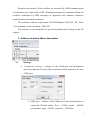
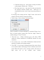
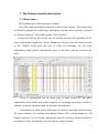
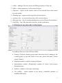
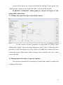
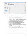
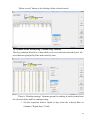
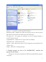
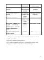
HARD-AND-SOFT SET OF ELECTRO-CHEMICAL PROTECTION (ECP) TELEMETRY SYSTEM (HSS-ECP) «DON-STEL-K» For remote control and operate of cathodic protection rectifiers are equipped by “KATRON-SKZ” controllers DESCRIPTION AND USER MANUAL SPE DONKONT LTD, SPE DON LTD/ Rostov-on-Don 2013 CONTENT 1. About software__________________________________________________2 2. Software structure. Menu description.________________________________3 2.1 Settings__________________________________________________3 2.2 Database_________________________________________________5 2.3 Report___________________________________________________5 2.4 «?» Help_________________________________________________5 3. Description of the software interface_________________________________6 3.1 Main window_____________________________________________6 3.2 Window the new object add (“Add” button)_____________________9 3.3 Window the properties object edit (“Edit” button)________________11 3.4 Window the object control (“Operate” button)___________________11 3.5 Window of the Reading log (“Reading log” button)_______________13 3.6 Window of the Archive log (“Archive log” button)_______________14 3.7 Window of the Messages log (“Message log” button)_____________15 3.8 Window of the Staff log (“Staff log” button)____________________15 4. “Hot buttons”___________________________________________________16 5. Variants of the software. Files structure of the software__________________16 6. Warning messages are sent by the controller and generated by the software__17 1 1. About software. The software of the HARD-AND-SOFT SET OF ELECTRO-CHEMICAL PROTECTION TELEMETRY SYSTEM “DON-STEL-K” (below will named as Software) is intended for remote monitoring and control of cathodic protection rectifiers (CPR) are equipped by “KATRON-SKZ” controllers. Basic functions of the software: - monitoring and visualization of the CPR current values as output voltage and current, protective potential, time counters and wattmeter values, type and settings of work mode, standby power supply and door sensor statuses; - reading of the archives from the controllers memory (up to 60 days depth with 1 hour averaging); - receiving of the warning messages from the CPRs and transmitting of them to local network PCs and to some e-mails; - transmitting to the CPRs controllers of the control commands and settings which including: settings of work mode (automatic/non automatic), settings of outputs voltage, currents and protective potential values, writing date, time, wattmeter’s type and telephone numbers for sending of warning messages to controller; - keeping logs of request results, warning messages and operator actions; - creating, printing and exporting of current parameters reports for all objects; - creating, printing and exporting of archives reports for every object for selected day; - keeping all data to database of MS Access format with possibility using them for automatic generation of reporting and analytic. All received data are saved to database and present in comfortable form to operator. 2 Requests and control of the rectifiers are executed by GSM communication in transmit/receive data mode (CSD. Warning messages are transmitted from the rectifiers controllers by SMS messages to registered cells numbers (inclusive central modem of terminal software). The minimal software requirement: OS MS Windows 2000, NT, XP, Vista, 7; the minimal screen resolution: 1024x768. The software is not demanded of special installation and writing to the OS register. 2. Software structure. Menu description. 2.1. Settings. Connection settings – settings of the COM-port and information receiving timeouts. Execute after connection of the modem to the new COM-port: COM-port – number of the COM-port to the which modem is connected. Default values: Port – COM1, speed - 9600По умолчанию: порт - СОМ1, скорость - 9600 бод; 3 Connection timeout, ms – time period of waiting of readiness to data transmit. Default value – 50000 ms; Receiving timeout, ms - time period for data receiving from the requested controller. Default value – 30000 ms. It is recommended set more value if some connection problems are had. For keeping of the settings push the “Apply” button. After that the software will work with new connection settings. Sound settings – buzzer setting of warning messages. There is possible to set buzzer through PC’s soundcard (Using of wavfiles) or system's speaker (system tones). Push the “Apply” button for confirm settings or “Cancel” for abort. Connection type – settings connection type to the object, GSMmodem for wireless connection or CAN/RS-485 interface for wired connection; View of main screen – to set visible of information columns and color indicators of mistakes and warning messages; Check SMS – for receiving of warning messages from remote objects to the terminal window and keeping of them in database activate this option. When this option is active, message window will present in right down site of the terminal main window. 4 After activation of this option, in “Settings” menu will be not available settings of connection and connection type. For restore of access to connection settings need deactivate “Check SMS” option; Exit – saving database and close software. 2.2. Database: Delete object – delete active object (marked blue background and cursor in line beginning ) and all data of it; Choose base – select database for work. Possible choosing any databases HSS DON-STEL-K on a local PC also on any other PC of local network. Create base – creating of blank database. This option works only if MS Access software is installed on the local PC. Attention! Before creating new database save reserve copy of current database (see Save base), else all data of current database will be lost! Save base – saving data of current database to the new file; 2.3 Report: Current data (option is active in main window) – generate report about current data of selected group of the objects; Archive data (option is active in Archive log window) – generate report for archive data of object for selected Date. 2.4 «?» Help: Help – short information file about HSS DON-STEL-K software; About – information about authors and manufacturer. 5 3. The Software interface description. 3.1 Main window. This window open when software is started. List of all connected objects shown in a table of the window. The objects may be shared by groups for comfortably and logical viewing. Active group is selected in “Group of objects” field (right up part of the window). Group of fields on the up left part of window are used for searching of the object with desired properties. In the "Parameter" field is selected search criteria, in the “Search” field write any text or value for searching. As you enter information, table pointer automatically goes to the more relevant record in the table. There is information line at down part of main screen. In this place information about COM-port status, progress of executing operations, results or mistake of current operations and current time are indicated. Information in main screen table may be sorted by increases and decreases for some columns. For sorting of required column click column header by left button of mouse. For every click, appropriate symbol of sorting will be indicated in the header’s body. Sorting may execute only for single column. 6 Columns which allow sorting: 1. # c/c; 2. # Ident.; 3. Address; 4. Tel. #; 5. Range of CPR; 6. kW*hour; 7. Hours (r); 8. Hours (t); 9. Reading Date. Lines of some objects may have color backlight when the software work: Brown – some problems of current values reading (lost connection or object is not available); Lilac – some problems of archive data reading (mistake of receiving data or incorrect clock of controller); Red – received warning message. “Auto reading” elements group allow to read current values and archives data of the current group objects or objects of all having groups by schedule in auto mode. Only objects are having active checkbox of group operations (first column of table) will be used for group request. In the opened window “Schedule” for the “Schedule settings” set the days, start time and period (from 1 up to 23 hours) for starting of auto request. In the “Current data reading” set request type for current group (“Reading of group”) or for all objects (“Reading of all”). In the “Archives reading” set active “On/Off Archive reading” checkbox for request of the archives data on. If the checkbox set active, set depth of reading archives in days (from 1 up to 60 days). 7 For activate of the schedule push “Ok” button or “Cancel” for abort settings. After activation of the Schedule, the software set on to auto mode and deactivate control's elements of the interface. For restore of the operator control (manual mode) push “Stop” button of the “Auto reading” section. Schedule will be deactivated. For starting of groups request of objects without schedule push “Reading of group” for request of current group objects or push “Reading of all” for request of all objects. Only objects are having active checkbox of group operations (first column of table) will be used for group request. For canceling of the group request push “Stop” button. All basic functions of the software are grouped by sections. Transition to the functions occurs by pushing buttons of the right navigation column of the software interface: 8 1. «Add» – adding of the new object and filling properties of this one; 2. «Edit» - editing properties of the selected object; 3. «Operate» - request of the current values of the selected object and control by work modes.; 4. «Reading log» - request results log of the selected object; 5. «Archive log» - received archives log of the selected object; 6. «Message log» - log of warning messages are received from selected object; 7. «Staff log» - log of the operators activities on this workstation.. 3.2 Window the new object add («Add» button) For adding of the new object fill next fields: Groups of objects (choose group name from drop-list for adding to the created group or type the name of the new group and push “Create group” button); Sequence number (used for sorting of objects); Identification number (Registration number of object from project documentation); Address – address of the object mounting; Tel. number – phone number of the object’s controller (number of installed SIM-card); 9 Installation Date – Date of starting to work of the object; Network address of objects controller – network address of the objects controller, default is 1 (used if some objects are united to local wired network); Duty tel. numbers – phone numbers of customers or terminals which will be receiving the warning messages and have access to the object for control by GSM connection. For configure of access rights make active needed checkboxes for each number. Wattmeter type – choose wattmeter type from drop-list; Reference electrode – on/off; Uout control of the off rectifier – on/off Pnom, V*A – nominal output power of the rectifier; Range of CPR – 1-normal voltage, 2-twice voltage. For adding of the new object push “Apply” button, for abort push “Cancel” button. If the subscription list of the object was filled, the software will start connection to the added object, make writing to the controller and exit to main screen after that. All added objects are ordered by structure is presented below. 10 Groups of the objects are created and deleted by pushing “Create group” and “Delete group” buttons in the “Add” and “Edit” sections of the software. WARNING! WARNING! When group are deleted, all objects of this group will be deleted too. 3.3 Window the properties object edit («Edit» button) In this section all basic properties of object may be edited. After edition push “Apply” button for keep changing or push “Cancel” button for abort operation. If the subscription list of the object was filled, the software will start connection to the added object, make writing to the controller and exit to main screen after that. 3.4 Management of the object (“Operate” button) This section is intended for executing of requests and control by modes and working of the object. 11 There are three subsections: 1. Current data – start request and indication of received data from the object: o Iout, A – value of output current DC of the CPR; o Uout, V – value of output voltage DC of the CPR; o Up.p., V – value of protective potential on the protected construction measured relative to a reference electrode; o R, Ohm –calculated value resistance of the circuit; o Рout, VA – value of a current output power of the CPR; o W, kW*h – current value of the wattmeter; o Hours (r) – time work at installed mode and value (useful time of work); o Hours (t) – full time counter of the CPR; o T, C – temperature value inside the controller’s box; o Uacc., V – voltage value of the controller’s accumulator and charge status. For receiving current data push “Read” button in this subsection. In the request process all fields will be filled and regulators set to appropriate positions. 12 Received data are saved to database and may be viewed in the “Log” section of the software at any time. 2. Operate of CPR. This subsection is intended to control by modes and parameter's values of the CPR and read of them. First regulator (“Regime A/P”) set auto (A position) or manual (P position) work modes of the CPR. Second regulator (“Subregime I/Up.p./U”) set one of controlled parameters of the CPR work: I – output current control, Up.p. – protective potential control (possible only for auto mode), U – output voltage (possible only for manual mode). Third regulator is intended for setting selected parameter’s value. For changing of this one to type digital value to field. For save settings push “Save” button. The software will connect to the object and change settings. For reading current settings of the object to push “Read” button. The current settings are showed in the “Reg./Set” column of the software main screen in format: A(P)/xx,x А(Р) – Auto mode (Manual mode); хх.х – value setting; А(V) – Amps (Volts). Example: A/2.3V – is auto mode stabilization of the protective potential 2.3V setting. 3. Date/Time of object’s controller – This subsection is intended for synchronization of the objects in time. After first start of the object to set correct values of Date and time push “Save” button. Check Date and time values periodically, because correct values are very important for archives data. For check values push “Read” button. 3.5 Window of the Reading log (“Reading Log” button) This Log contains information about all data values which were received for each request. All saved data are grouped by Date and sorted by time. There is calendar element in the right down part of window. The days with request's data are marked by bold font. 13 “Delete record” button is for deleting of the selected record. 3.6 Window of the Archive log (“Archive log” button) This Log contains all archive’s data which were received from selected object. All saved data are grouped by Date and sorted by time. There is “Reading settings” elements group for reading of archives data from the selected object and for reading setting: o Set the requested archive depth in days from the selected Date in calendar (“Depth, days” field); 14 o Switch the type of request: “Current object” – request only selected object; “Current group” – request all objects of it’s group; “All groups” – request all objects of all groups. For start of archive data request push “Read” button. For abort of archive request push “Abort” button, after that the software will finish current connection and cancel operation. For deleting data of selected day’s push “Delete day” button. 3.7 Window of the Messages log (“Message log” button) This Log contains texts of the warning messages which was received from selected object or generated for it by the software. For deletion of the selected message push “Delete the message” button. 3.8 Window of the Staff log (“Staff log” button) This Log contains information about all actions of software operator. All saved data are sorted by Date and time. This Log is not editable. 15 4. “Hot buttons” list Buttons Actions Ctrl + Del Deleting selected object Ctrl + S Saving current database to the new file Alt + Ctrl + O Enable service mode Alt + Ctrl + P Disable service mode 5. Variants of the software. Files structure of the software Software is available in electronic, optical media or delivered by e-mail. We recommend installing the software in a dedicated folder on the user's hard drive. Also possible using the software from flash-drive or portable hard disk. The file structure of the software present below: 16 Katod.exe – executed file, used for start of the software. KatodProtect.mdb – database file in MS Access format. This one used for keep all data and has open structure for creation users forms and reports. WS_names.wsn – file settings for translation of received warning messages to some PC on local network. templateDB.mdb – template file for creation of the new database. TurboVideo.wmv – promotion movie file. LogFiles – folder with log files (Service files for diagnostics some problems of the software work). Sounds – audio files of warning messages. 6. Warning messages are sent by the “KATRON-SKZ” controller and generated by the software - Messages are sent by the controller have SMS format and tariffed by operator connection.: 17 Event TRIPPED THE DOOR SENSOR Message text in Message text in the mobile phone software terminal ВХОД НЕ TRIPPED THE DOOR НОРМА/DOOR SENSOR SENSOR TURNING OFF THE AC POWER НЕ НОРМА TURNING OFF THE АС220В/AC220V AC SUPPLY IS OFF RESTORE AC POWER НОРМА RESTORE AC POWER АС220В/AC220V IS ON FAULT. THE CPR HAS NOT -АВАР-/- POSSIBLE TO WORK IN FAULT- EMERGENCY MODE SETTING MODE. THE CPR WORK IN EMERGENCY MODE. THE CPR IS RESTORED IN -НОРМА- Штатный режим SETTING MODE - Messages are generated by the software when data from object are received (not SMS – not tariffed): «CPR is off» - generated if setting value is 0; «CPR’s mode was changed by other users» - generated if the software define changing of work mode or setting value to relation previously set. 18


![CAST for PSI user`s manual [v07]](http://vs1.manualzilla.com/store/data/005903758_1-a858c2dfda3ffb28451a6ec48d1cfa02-150x150.png)