1
US007577910B1
(12) United States Patent
Husemann et a].
(54)
METHOD AND APPARATUS FOR
6,792,605 B1 *
PROVIDING A MORE POWERFUL
USER-INTERFACE TO DEVICE WITH A
LIMITED USER-INTERFACE
(75) Inventors: Dirk Husemann, Adliswill (CH);
Michael Moser, Zurich (CH)
(73) Assignee: International Business Machines
Corporation, Armonk, NY (US)
(*)
Notice:
Subject to any disclaimer, the term of this
patent is extended or adjusted under 35
U.S.C. 154(b) by 1343 days.
(EP)
FOREIGN PATENT DOCUMENTS
JP
JP
JP
JP
JP
JP
JP
W0
W0
07-254920
l0-l62060
l0-240833
11-027290
11-031114
ll-l6l32l
2002-509669
WO 95/28673
WO 98/59284
l0/l995
6/1998
9/1998
l/l999
2/1999
6/1999
3/2002
l0/l995
l2/l998
OTHER PUBLICATIONS
Jaap Haartsen, “BluetoothiThe universal radio interface for ad hoc,
wireless connectivity”, Ericsson Review No. 3, 1998.
Christer Erlandson and Per Ocklind, “WAPiThe wireless applica
tion protocol”, Ericsson Review No. 4, 1998.
Foreign Application Priority Data
Jul. 12, 1999
Roberts et al. ............ .. 719/313
2000.
Jul. 10, 2000
(30)
9/2004
European Search Report, Application No. EP 99 111 3414, Mar. 21,
(21) App1.N0.: 09/613,113
(22) Filed:
US 7,577,910 B1
Aug. 18,2009
(10) Patent N0.:
(45) Date of Patent:
................................ .. 99113414
* cited by examiner
Primary ExamineriBa Huynh
(51)
(52)
Int. Cl.
G06F 3/00
(74) Attorney, Agent, or FirmiBrian P. Verminski, Esq.
(2006.01)
US. Cl. ..................... .. 715/744; 715/745; 715/746;
(57)
ABSTRACT
715/747
(58)
Field of Classi?cation Search ............... .. 345/716,
A method and apparatus for controlling a computer device
345/719, 720, 721, 723, 730; 7l5/744i749
with a limited user-interface via a remote computer device
having a more powerful user interface. Both computer
devices are interconnected via a wireless communication
channel and both computer devices support a common com
See application ?le for complete search history.
(56)
References Cited
munications protocol. User-interface information is sent from
U.S. PATENT DOCUMENTS
6,173,316 B1 *
1/2001
De Boor et al. ........... .. 709/218
6,216,158
B1 *
4/2001
Luo et al.
6,446,096
6,456,892
6,466,971
6,502,000
B1
B1
B1
B1
*
*
*
*
9/2002
9/2002
10/2002
12/2002
.......
. . . ..
709/217
Holland et al. ............ .. 715/513
Dara-Abrams et al. ...... .. 700/83
Humpleman et al. ...... .. 709/220
Arnold et al. ............... .. 700/83
6,509,913 B2*
1/2003 Martin et al.
6,560,640 B2 *
5/2003
the computer device with a limited user-interface to the
remote computer device to provide a user-interface at the
remote computer device for receiving user input at the remote
computer device. The user input controls the computer device
with a limited user-interface to execute commands therein
corresponding to the user input.
345/762
26 Claims, 10 Drawing Sheets
Smethers .................. .. 709/219
103
receive service
information
background
user requests (list of) devices
send user input to device
US. Patent
Aug. 18, 2009
Sheet 1 0f 10
US 7,577,910 B1
16
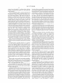
brought
into vicinity
FIG. 1
I/deIauIt-IontsI
Vlmer'aw
I/baud-raté]
'I/parity
[/lorrhéts
F
I
I
PJCL.
[/PostScript I
FIG. 2
US. Patent
Aug. 18,2009
US 7,577,910 B1
Sheet 2 0f 10
I |
15E
'
12
,36
' blueloolhJIsony_cdp_990)<.lmain_merlu.wml
General settings
Welcome to
SONY CD-Player 990x
32~
‘
/ _, 33
play_mode
CO_names d f
Please select the function you want lo
con?gure:
help
|"“’'37
. CD labels
3.
35~ -~Play
mode
7
30
FIG. 3
US. Patent
Aug. 18, 2009
Sheet 3 0f 10
US 7,577,910 B1
URL: uh'?sony_cdp_990)<!main_menu.wml#CD_naes
CD names.-
Generalsmings
Enter a name for the currently inserted
co-mm“
CD1
play__rnode
1
!
i;
help
,35
,/
_ 34
:1
_/'5'7
/""_’4O
FIG. 4
US. Patent
Aug. 18, 2009
Sheet 4 of 10
(A e‘. ‘M ; ,. ..‘_,
US 7,577,910 B1
K,
_ E j
31
éURL: bluetoolhJlsony__cdp_Q90>(Imain_menu.wm|#play
2
Play modes.
_
-
Select one ofthe following play
.
modes.
"play-modes:
.6 or“?
9 /,
enen semn
s
cgmms
phyjnode /} ,_../”34
Mp
~13?
6) Normal
(3 Random
51
O Shu?le
C- User-De?ned
5M
U
‘50
J
52
FIG. 5
US. Patent
Aug. 18, 2009
Sheet 5 0f 10
US 7,577,910 B1
FIG. 6
US. Patent
Aug. 18, 2009
Sheet 6 0f 10
US 7,577,910 B1
[73 _L.0
[72
I
transmitter
driver
MAC
protocol
2
receiver
driver
\74
user interface
[79
application
[a
HW-driver(s) 1Q
manager
device speci?c
70/
Fli'L
FIG. 7A
2i 3 1i
5:28.
B23
DOE2:
33:MT86:
DmU7
IL
2f
US. Patent
Aug. 18, 2009
Sheet 7 0f 10
US 7,577,910 B1
[730
[720
I
transmitter
driver
MAC
protocol
receiver
driver
UmnSoa.nm.ngmurn
C
M.1
l0
f
750
user interface drivcr
700/
(IL
FIG. 7B
7€l 1%)2
03 7Y4
0
5:2.
b0oEruE
EU“.
3.55805:7
82320v
00
FIG. 7C
US. Patent
Aug. 18, 2009
8761
H
Sheet 8 0f 10
US 7,577,910 B1
. .
. . - - - - - "
'
W
‘pamadlukllj
send service
information
background
'
L“
._
I
_______
A
‘
I '
_ _
Mwfer.
87
receive input & {-88
categorize cond.
request to
send UI
f 89
information: > - ' ' - - ' -.
/
update own US!
Send UI
handle/execute
with services
description
user input
7
\
I .
.
.
.
.
.
.
.
35
[90
send feedback
FIG. 8
US. Patent
/02
Aug. 18, 2009
Sheet 9 0f 10
US 7,577,910 B1
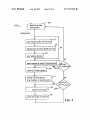
‘'3receive service 1/103
I
information
I‘
a
background
91
user requests (list of) devices
/92
I
display list of controllable devices
—93
user selects device
send request to send [II-description
Y
_
/-—96
receive UI-descn'ption
render UI-description
(e.g. display or read to user)
/
['6CCIVC USCI' input
send user1input to device
_
US 7,577,910 B1
1
2
METHOD AND APPARATUS FOR
PROVIDING A MORE POWERFUL
USER-INTERFACE TO DEVICE WITH A
LIMITED USER-INTERFACE
cation feature (such as the Casio PC Unite Data Bank Watch,
HBX-lOOB-l) used to connect to a PC.
There are many other examples of user-interfaces that are
severely lacking for various reasons, the most prominent of
Which are siZe and cost constraints. Often such user-interface
restrictions make the respective devices less useful for their
oWners than they could be.
TECHNICAL FIELD
The present invention relates to computer systems Which
It Would thus be useful to have a Way to unleash the full
have a limited user-interface, such as hand-held pervasive
potential of all these devices and to program and con?gure
them much more conveniently, thereby making them more
computing devices, and in particular to a design for allowing
easy interaction With such computer systems.
useful to their users.
There is groWing demand in the industry to offer devices
BACKGROUND OF THE INVENTION
that are ‘open’ in the sense that a user has access via an
interface to the device’s processor or other components. An
Through relatively recent technological innovations, com
ideal ‘open’ device Would be fully controlled by the user,
puter systems have become dramatically smaller and more
preferably Within Well-de?ned rules to prevent misuse or
destruction of the device itself.
In addition, there are a groWing number of devices that are
netWork enabled, Which means that they can communicate
portable. Even very poWerful personal computers (PCs), for
example, are small enough to sit on the desk at Work. Smaller
still are lap top computers and notebook computers. There are
computer terminals Which are small enough to be mounted in
a vehicle, such as a delivery truck. Still smaller are hand held
20 With one or more other devices via a netWork. This can be
achieved using physical connections, such as cables or ?bers,
terminals, Which are typically used for their portability fea
for example. As these devices get smaller, hoWever, it
becomes desirable to replace the physical connections With
tures, alloWing a user to carry the terminal in one hand and
operate it With the other.
In addition, there is a trend toWard offering consumers
electronic devices that include some sort of computer system,
Wireless connections (e.g. body netWorks, radio frequency
25
e.g., a microprocessor. Usually, these computer systems not
only control the operation or function of the consumer device,
reduces the ef?ciency gained by making the units smaller.
Ad-hoc Wireless connections are required Where devices
but also provide some interface for a user or operator to
control certain functions or parameters according to actual
needs. It is in the nature of these consumer devices that they
do not have a full user-interface like a computer With display
move around, enter an area and exit the area. The term ad-hoc
30
In addition, there are many different knoWn communica
and keyboard. It is not likely that a dishWasher, for example,
designed (and continue to be developed and designed)
35
for this is a Wrist Watch), While in other cases the interface is
limited to keep the cost of manufacturing loW, While still in
other cases the processing poWer of the computer system, or
the constrained memory space, limits the interaction betWeen
the user and system.
Many of today’ s devices have an inadequate user-interface.
refers to the need for frequent netWork reorganiZation.
tions protocols or standards that have been developed and
Will ever have such a full user-interface. In some cases the
interface is limited due to space constraints (a typical example
connections, or infrared connections), since physically con
necting the devices by means of cables or ?bers severely
directed at communication betWeen devices or subsystems.
HereinbeloW, some Wireless communications protocols or
standards Will be mentioned. There are many ?ber or cable
based, standardized approaches that are suited for such com
munication as Well.
40
GTE Corporation has developed a short-range radio-fre
quency (RF) technique Which is aimed at giving mobile
A typical example is a compact disk (CD) player Which
devices such as cellular phones, pagers and hand-held per
sonal computers (PCs) a smart Way to interact With one
alloWs programming of CD titles using a small four button
control. Programming of such a CD player is very cumber
another. GTE’s technique is tentatively named Body LAN
(local area netWork). The original development of Body LAN
some because one needs to use the buttons to move through 45 Was via a Wired vest With Which various devices Were con
the entire alphabet to select letters and/or numbers. Another
example is a Wrist Watch that alloWs the user to enter phone
nected (hence the name Body LAN). This then developed into
book entries, appointments, and to-do items. Typically, the
Xerox Corporation has developed a hand-held computing
device called PARC TAB. The PARC TAB is portable yet
connected to the of?ce Workstation through base stations
Which have knoWn locations. The PARC TAB base stations
are placed around the building, and Wired into a ?xed Wired
netWork. The PARC TAB system uses a preset knoWledge of
the building layout and the identi?ers of the various base
stations to determine the strongest base station signal for a
PARC TAB portable device. A PARC TAB portable device
keyboard includes a very limited number of keys. Further
more, the display is small and its resolution limited. Certain
keys have to be pressed several times to reach special char
acters, or to activate special functions. Yet another example is
a personal digital assistant (PDA) With a touch sensitive
to an RF connection.
50
screen. In this case the screen occupies most of the device’s
surface and there are very feW buttons, if any. Some functions
are easily accessible using a pointing device, but other func
tions have to be selected or activated ?ipping through several
layers of menus, for example. Other examples are telephones,
vending machines, microWave ovens, mobile phones, etc. For
the purposes of the present description these devices are
55
has a Wireless interface to the base stations. The PARC TAB
system assumes that the PARC TAB portable device is alWays
connected to the netWork infrastructure. The location of each
60
referred to hereinafter as user-interface limited devices.
Currently there are a feW approaches using a personal
computer (PC) to run better user-interfaces, eg the “Nokia
Cellular Data Suite” for mobile phones alloWs the entry of
phone book data. The Cellular Data Suite is a hardWare and
softWare package from Nokia designed for cellular phones.
Another example is a Wrist-Watch that has an IR-communi
portable PARC TAB device is alWays knoWn to the system
softWare. The base stations establish regions and are con
nected to poWer supplies. PARC TAB communication sys
tems have a star topology.
In an attempt to standardiZe data communication betWeen
65
disparate PC devices, several companies, including Ericsson,
IBM, Intel, Nokia, and Toshiba have established a consortium
to create a global standard for Wireless RF-based connectivity
US 7,577,910 B1
3
4
between ?xed, portable and mobile devices. There are many
ing Group’s web site http://www.homerf.org. The SWAP
speci?cation 1.0 is incorporated by reference in its entirety.
other companies adopting the proposed standard. The pro
posed standard is called Bluetooth and comprises architecture
There are several other known protocols and techniques
and protocol speci?cations ranging from the physical layer up
that allow communication between two or more devices. The
to the application layer. The Bluetooth standard contemplates
above described Bluetooth radio technology and HomeRF
allowing users to connect a wide range of devices easily and
approach are prominent wireless examples.
quickly, without the need for cables, expanding communica
tions capabilities for mobile computers, mobile phones and
other mobile devices. The Bluetooth operating environment
is not yet fully de?ned, but similarities are expected with the
IrDA (Infrared Data Association) speci?cation and the
Advanced Infrared (AIr) speci?cation. It is not unreasonable
to expect that the Bluetooth standard will eventually incorpo
SUMMARY OF THE INVENTION
It is therefore an object of the present invention to provide
a method and apparatus for providing a more powerful user
interface to a device with a limited user-interface.
It is another object of the present invention to provide a
method and apparatus for simpli?ed and improved user inter
rate aspects of the IEEE standard 802.1 1 and/ or HIPERLAN,
as promulgated by the European Telecommunications Stan
dards Institute (ETSI).
Bluetooth radio technology provides a standard protocol
suitable for forming small private ad-hoc groupings of con
action with a device with a limited user-interface, also
referred to herein as an “interface limited device.”
Bluetooth makes a distinction between a master unitiwhich 20
To achieve the above objects, a method and apparatus in
accordance with the present invention includes a standard
wireless communications protocol which allows a user to
interact with or control an interface limited device wirelessly
is a device whose clock and hopping sequence are used to
using a second (independent) device.
synchronize all other devicesiand slave units in the same
In other words, the present invention provides a more pow
erful user-interface to an interface limited device by interfac
ing it with a more powerful device in its vicinity. The more
nected devices away from ?xed network infrastructures.
network segment. In other words, the Bluetooth approach is
centraliZed. A query-based discovery design is used for ?nd
ing Bluetooth devices with an unknown address. Queries are
25
extensive input capabilities of the more powerful device (sec
also centraliZed at a registry server. Further details can be
ond device) are employed to control certain aspects of the
found in Haartsen, Allen, Inouye, Joeressen, and Naghshineh,
limited user-interface device (?rst device).
“Bluetooth: Vision, Goals, and Architecture” in the Mobile
Computing and Communications Review, Vol. 1, No. 2.
Mobile Computing and Communications Review is a publi
The method in accordance with the present invention
includes the steps of transmitting user-interface information
30
cation of the ACM SIGMOBILE.
HomeRF (based on Shared Wireless Access Protocol
interface information; receiving user input via the user-inter
(SWAP)) is another example of a prospective operating envi
ronment protocol which can be used to connect devices. A
HomeRF Working Group was formed to provide the founda
from the ?rst device to the second device; providing a user
interface at the second device corresponding to the user
35
tion for a broad range of interoperable consumer devices by
face at the second device; transmitting user command
information corresponding to the user input from the second
device to the ?rst; and executing the corresponding user com
mands at the ?rst device.
establishing an open industry speci?cation for wireless digi
tal communication between PCs and consumer electronic
devices anywhere in and around the home. The working
group, which includes the leading companies from the per
DESCRIPTION OF THE DRAWINGS
40
sonal computer, consumer electronics, peripherals, commu
nications, software, and semiconductor industries, is cur
rently
developing
a
speci?cation
for
following detailed description of an exemplary embodiment
thereof taken in conjunction with the attached drawings in
wireless
communications in the home called the SWAP. The HomeRF
SWAP system is designed to carry both voice and data tra?ic
45
and to interoperate with the Public Switched Telephone Net
work (PSTN) and the Internet. It operates in the 2400 MHZ
band and uses a digital frequency hopping spread spectrum
radio. The SWAP technology protocol being developed is
being derived to some extent from extensions of existing
cordless telephone (DECT) and wireless LAN technology to
present invention;
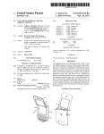
FIG. 3 illustrates a ?rst user-interface window in accor
dance with an embodiment of the present invention;
supporting both a time division multiple access (TDMA)
service to provide delivery of interactive voice and other
FIG. 4 illustrates a second user-interface window in accor
55
dance with an embodiment of the present invention;
FIG. 5 illustrates a third user-interface window in accor
collision avoidance (CSMA/CA) service for delivery of high
speed packet data. The SWAP system is contemplated to
operate either as an ad-hoc network or as a managed network
under the control of a connection point. In an ad-hoc network,
where only data communication is supported, all stations will
be equal and control of the network will be distributed
which:
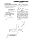
FIG. 1 is a block diagram illustrating a typical environment
wherein the present invention is utiliZed, in accordance with
an embodiment of the present invention;
FIG. 2 is an illustrative representation of an exemplary
execution tree in accordance with an embodiment of the
50
enable a new class of home cordless services. It envisions
time-critical services, and a carrier sense multiple access/
The above and other objects, features and advantages of the
present invention will become more apparent in light of the
60
dance with an embodiment of the present invention;
FIG. 6 is a block diagram illustrating another embodiment
of a typical environment in which the present invention is
utiliZed, in accordance with an embodiment of the present
invention;
between stations. For time critical communications such as
FIG. 7A is a block diagram illustrating a ?rst device (with
interactive voice, the connection pointiwhich provides the
a limited user-interface) in accordance with an embodiment
of the present invention;
gateway to the PSTNiwill be required to coordinate the
system. Stations will use the CSMA/CA to communicate with
a connection point and other stations. Further details about
HomeRF can be found at the Home Radio Frequency Work
65
FIG. 7B is a block diagram illustrating a second device
with a more powerful user-interface) in accordance with an
embodiment of the present invention;
US 7,577,910 B1
6
5
addressing design is also required in a GSM-based imple
FIG. 7C is a block diagram illustrating the hardware layer
mentation of the present invention.
It is understood by those skilled in the art that at the present
of a second device in accordance with an embodiment of the
present invention;
time many of the protocols that are suited for use in wireless
communications systems are still in draft status. The present
FIG. 7D is a block diagram illustrating the hardware layer
of a ?rst device in accordance with an embodiment of the
design is independent of any one particular protocol and can
be used in connection with many such protocols. Accord
ingly, someone having ordinary skill in the art is able to
present invention;
FIG. 8 is a ?owchart illustrating the method of the present
invention in a ?rst device, in accordance with an embodiment
implement the present design in existing protocol environ
of the present invention;
ments as well as in protocol environments under development
or yet to be developed.
FIG. 9 is ?owchart illustrating the method of the present
invention in a second device to control a ?rst device in accor
The present design can be used anywhere inside, i.e. ware
dance with an embodiment of the present invention; and
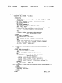
FIG. 10 is a Wireless Markup Language (WML) document
describing the user-interfaces of FIGS. 3-5.
houses, on manufacturing ?oors, in o?ices, on trading ?oors,
in private homes, and outside of buildings, in cars and trucks,
in airplanes, just to mention a few examples.
DESCRIPTION OF PREFERRED
EMBODIMENTS
For the purpose of the present description, a network can be
anything that allows a ?rst device (the limited user-interface
20
device) to communicate with a second device (which has a
more powerful user-interface).A simple point-to-point link, a
local area network (LAN), a GSM telephone link, an ethernet
link or any other kind of link is hereinafter referred to as
25
network. This network can either be a physical network or a
wireless network (e.g., infrared (IR), radio-frequency (RF),
such as HomeRF). The network may be completely isolated
from any other network, or it might comprise one or more
access points which provide the devices with access to
another network.
The speci?c range that constitutes a wireless network in
accordance with the present invention depends on actual
implementation details. Generally, a wireless network can be
Details about HummingBird transceivers are given in
30
can establish a network connection to another device.
Examples of devices are: laptop computers, workpads, node
pads, personal digital assistants (PDAs), notebook computers
40
computing systems, set-top boxes, cash registers, bar code
scanners, point of sales terminals, kiosk systems, cellular
phones, pagers, wrist watches, digital watches, badges, and
45
and voice access points, cameras, printers, fax machines,
keyboards, joysticks, HiFi systems, audio (sound) cards,
loudspeakers, ampli?ers, video cards, kitchen appliances,
the Haartsen, Allen, Inouye, Joeressen, and Naghshineh,
It is assumed, that once the devices are in vicinity of each
other, a wireless communication path between these devices
50
Other examples of devices that can be used in connection
with the present invention are, personal effects being
55
low-power radio-frequency (RF) communication, e.g. Blue
60
examples of wireless schemes that are suited.
Of course such a vicinity requirement may also be accom
net), thus effectively allowing remote control of a variety of
devices from virtually anywhere in the world. Such a global
equipped with computer-like hardware, such as a “smart wal
let” computer, jewelry, or articles of clothing. In addition to a
“smart wallet” computer, there are a number of other varia
tions of wearable computers. A “belt” computer is such a
variation which allows the user to surf, dictate, and edit docu
ments while they are moving around. Yet another example is
a child’s computer which is comparable to a personal digital
assistant for grade-school children. The child’s computer
might hold assignments, perform calculations, and help kids
plished via some global addressing design and a local proxy
(e. g. an IR-beacon on each ceiling or a BlueTooth “relay” in
each room or home) connected to a network (eg the Inter
tools, sensors such as smoke and/or ?re detectors, and virtu
ally any other digital device.
can be established4e.g. using magnetic ?eld (near ?eld/5-30
cm), infrared (IR), e.g., IrDA (0.5-2 m) or AIr (1-10 m), or
Tooth (71-10 m), or HomeRF (71-50 m), just to list some
smart cards. Other contemplated devices include: headsets,
Human Interface Device (HID) compliant peripherals, data
Well suited to support communication between devices is
the Bluetooth communications design, which is described in
“Bluetooth: Vision, Goals, and Architecture” in the Mobile
Computing and Communications Review, Vol. 1, No. 2.
Mobile Computing and Communications Review is a publi
cation of the ACM SIGMOBILE. This reference is incorpo
rated herein by reference in its entirety.
and other wearable computers, desktop computers, computer
terminals, networked computers, internet terminals and other
information via the network. Accordingly, two devices that
communicate with each other must support the same commu
and selection of communication partners, etc. depend on the
medium used and the communications protocol employed.
When referring to a device, any kind of device is meant that
case of a GSM network). Under certain circumstances the
communication range may go even further. The two
devicesiwhich communicate with each other have to be “in
nication protocol.
Manual”, Rev. 24 Jun. 1998, XETRON Corp., Cincinnati,
Ohio, USA
Details concerning the basic problems regarding identi?
cation and addressing, initial (resource) discovery, matching
meters and several thousands of square kilometers (e.g., in
or otherwise interconnected in order to be able to exchange
information with each other.
The devices need to be able to transmit and/or receive
medium. A possible shared medium is RF (Radio Frequency).
Possible systems could be based on technology and protocols
like BlueTooth, DECT, and HummingBird.
“Hummingbird Spread Spectrum Transceiver Operator’s
described as having a coverage area between a few square 35
vicinity,” which means that they have to be suf?ciently close
Two devices can be connected using a 1:1 connection.
Possible media are infrared and magnetic ?elds. The proce
dure to setup such a 1:1 connection can be similar to today’s
setup of a connection between two IrDA enabled devices, i.e.
the devices must be positioned such that their communication
subsystems (transceivers) can “see” each other. Then both
systems are triggered to start a connection setup procedure
until a wireless communication channel is established.
Likewise, two devices can be connected using a shared
manage their homework. It can interface with other children’ s
computers to facilitate collaboration, and it can access a
65
teacher’s computer to download assignments or feedback.
Any wearable or portable device, any of?ce tool or equip
ment, home tool or equipment, system for use in vehicles, or
US 7,577,910 B1
7
8
systems for use in the public (i.e. vending machines, ticketing
machines, automated teller machines, etc.) may include the
present invention.
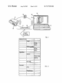
?rst device 10 by transmitting a more poWerful user-interface
(user-interface description 15) stored in the ?rst device 10 to
the second device 12. The ?rst device 10 and second device 12
communicate via a Wireless communications channel 16. A
more poWerful user-interface is a user-interface that is easier
to use, ie “richer” (in that it has more features), more intui
tive, faster, or the like. The user-interface description 15 is
then processed by the second device 12 such that the more
It is also assumed that a device, as used in connection With
the present invention, includes a minimum amount of pro
cessing poWer to enable it to participate in the design accord
ing to the present invention. These devices are thus also
referred to as computer devices. Most, if not all, of the above
listed devices may be vieWed as being devices With limited
poWerful user-interface 19 is then displayed and operated via
the second device 12. Then user-inputs and/or commands
user-interfaces. This may even be the case for a personal
computer Which has a display and a keyboard. There is still
room for improvement in such a computer’ s interface, e. g., by
adding speech input. There are no absolute criteria Which can
be used to decide Whether a particular device is a device With
and/or parameters are sent back to the ?rst device for execu
tion. In the present example, commands 17 (<command>)
and parameters 18 (<parameters>) are sent back to control or
operate the ?rst device 10 in response to commands input by
a limited user-interface or not. There is alWays room for
a user on the second device 12.
improvement and thus any computer device per se is assumed
The ?rst device 10 may provide its user-interface in some
standard format (herein referred to as a user-interface descrip
tion 15) to be broadcast to all other devices, such as the second
to be a device With a limited user-interface. The present inven
tion may be implemented Where there is a second computer
device 12, appearing in vicinity. If the user-interface descrip
device that has a more poWerful user-interface, more
adequate, more convenient, or superior user-interface capa
bilities. Not all aspects of the user-interface have to be supe
rior or more powerful. It is suf?cient, for example, if there is
a ?rst device Which has no speech input (i.e. it has a limited
user-interface) and a second device Which has a speech input.
The present invention may also be implemented, as selected
20
tion 15 is suf?ciently small then the entire interface descrip
25
tion can be transmitted quickly and stored at these other
devices.
If there are a plurality of devices (“controllable” devices)
With limited user-interfaces in vicinity of a second device
With a superior user-interface, then the user requests some
visual veri?cation on the second device listing all “control
lable” devices (e.g., in the form of a list, a menu, a graph, or
the like) from Which he/ she can then choose one device With
a limited user-interface and request its user-interface to be
by a user, to control the second computer device that has a
more poWerful user-interface via the device With the limited
user-interface, if so desired as a users convenience dictates.
Some of the above-mentioned devices can be regarded
hereinafter as the device (controller) Whose interface is used
to interact With the user-interface limited device (controlled
30
displayed, thereby beginning the aforementioned process,
device).
according to the present invention.
The communication path 16 betWeen the ?rst device 10 and
A computer device is generally referred to as a computer
device With a limited user-interface Where, for example, one
or more of the folloWing applies: the user-interface is inad
mand from the ?rst device 10 (thus becoming the “controlled
device” or server) to the second device 12 in vicinity (the
second device 12 is used to transfer data for a speci?c com
35
equate for the tasks required; the user-interface is small and
dif?cult to read, understand, or hear; the user-interface pre
controller or client/user agent). The second device 12 pro
vides the user-interface description 15 to the user. This can be
sents an inconvenience to the user; there is no graphics
done by displaying it (reference number 19) to the user on
capable display (e. g. a text-only display); there is a restricted
number of input keys, or input keys Which are too small; there
display 14, for example. Then, the second device 12 aWaits
40
The user enters responsive commands, eg by picking
his/her choice from a presented menu, or supplies input by
are too many functions Which are mapped to a limited number
of buttons and thus imposes complicated control structures
that make it dif?cult to operate the device Without prior exten
sive study of a user’s manual, especially for seldom used or
advanced functions; the user-interface is not poWerful
enough, making its use to sloW, or has loW resolution, or the
like.
Devices With a more poWerful user-interface capabilities
generally ful?ll, for example, one or more of the folloWing
criteria: there is a larger screen; there is a screen With graphics
keying-in the requested data. In doing so the user makes use
of the controller-device’ s more poWerful user-interface capa
45
interaction, selection, or input is then sent back to the con
and4optionallyione or more parameters 18) via the com
50
capability; there is a full keyboard; there is a pointing device;
munication path 16.
The controlling device 12 is not required to have any prior
knoWledge of the features and the user-interface of the con
trolled device 10. No special softWare needs to be pre-in
55
tion input, tactile input, etc.
A typical environment Where the present invention is used
stalled because everything is dynamically doWnloaded from
the controlled device 10 When required. Any Laptop or PDA
that happens to be handy, or maybe even a public kiosk
system, could quickly be used as a “user-interface server”
Without installing anything and Without leaving any notice
is illustrated in FIG. 1. There is a ?rst computer device 10
Which has a limited user-interface 11 (in the present example
the user-interface comprises a simple display and a feW but
tons). When there is a second computer device 12 in vicinity
of the ?rst device 10 that has superior user-interface capabili
ties (keyboard 13 and display 14) than that of the ?rst device
10 and Which may be controlled or con?gured, and assuming
that the tWo devices 10 and 12 communicate With each other,
bilities (be it a larger keyboard 13, voice-recognition, color
display 14, or the like). Information describing the user’s
trolled device 10 in the form of “requests” (i.e. commands 17
there is a voice-input feature and so forth.
The user-interface may be any kind of interface used for
interaction betWeen a user and the device, such as a display,
keyboard, mouse, track point, audio output, speech recogni
the user’s interaction.
60
able traces on that system (except maybe a feW modi?ed
cache-entries in the system’ s memory). HoWever, there are of
course some prerequisites Which must be ful?lled by all
involved devices to alloW the aforementioned interfacing.
One such prerequisite requires that both devices have a
standardized procedure and format of describing suf?ciently
65
rich user-interfaces such that it is possible to render typical
the superior user-interface capabilities of the second device
user-interface controls, i.e. display input-prompts, selection
12 may be employed to facilitate and speed-up the use of the
menus, help-texts or other text-messages to visualiZe a
US 7,577,910 B1
9
10
device’s status, etc. Suitable candidates for such user-inter
The present invention implements any suitable design used
for broadcasting and/or discovery of service offerings of the
face description formats are: HTML (the HyperText Markup
Language used in the WWW), WML (Wireless Markup Lan
guage de?ned by the WAP forum), other, still-to-be-de?ned
XML (Extensible Markup Language) dialects, and X-Win
doWs protocol.
particular design. What is required is that a device having a
One preferably uses a user-interface description Which is
optimized so that transmissions betWeen devices are ef?cient.
limited user-interface. The service information is updated
frequently, since the Wireless netWorks composition may
The user-interface description is preferably ?exible and
change frequently.
extensible.
In addition, the devices must be able to detect each other’ s
devices Within vicinity to determine Whether certain services
devices as described above, Without being limited to any one
more poWerful user-interface receive and store service offer
ing information describing those devices in vicinity having a
In one example, a resource discovery design may alloW tWo
presence, exchange basic capability descriptions andion
description can be a simple ?ag or bit combination, for
example, Which describes standard types of services. These
standard types of services may be prede?ned such that they
are available and What kind of services are available. A ?rst
device maintains a record With information about services
and associated identi?ers about a second device, Which acts
as a service-providing device. The ?rst device may comprise
a service discovery module Which maintains a record With
information about services and associated identi?ers, and a
can be identi?ed by a simple ?ag or bit combination. The
basic capability description can also be any other kind of
list of identi?ers about service-providing devices. The service
discovery module enables the ?rst device to distinguish a
demandibe able to setup a suf?ciently reliable point-to
point connection amongst each other. This basic capability
information Which is Well suited to identify one or several of
the services offered. In addition to identifying a type of ser
vice, one might have to set or de?ne certain parameters and
20
options (referred to hereinafter as parameters).
Thus, there are certain common requirements betWeen
devices. The devices, for example, Will initiate a resource
25
discovery design and exchange a capability and/or device
class description for describing their respective service offer
30
tial devices, and upon detection of other devices in vicinity,
upload information describing their service offerings. In
addition, it is advantageous if a device is able to signal its
presence to other devices and to doWnload its oWn service
offering information or (broadcast it) to the other devices. The
broadcast of service information may optionally be done
35
using a different protocol layer than the layer eventually used
vice is offered and by What device (i.e., all devices XYZ offer
the services A and B, and all devices MNO offer the services
C and D, for example).
An example of a design for broadcast and/ or discovery of
service offering information is addressed in a co-pending
40
45
“language”; WML has a relatively small and simple broWser,
“deck-of-cards” metaphor maps perfectly to familiar con
currently assigned to the assignee of the present application,
?guration paradigms (“property-sheets” or “tabs”); WML
50
user-interface description and receive the corresponding
commands) available. The general approach is that a group of
55
can be encoded very compact using either binary WML or
tokeniZed WML. Most tags become single-byte items and
strings are collected in a string-table. In the example given
beloW the original WML ?le is 1.5 kB, While the tokeniZed
form is only 652 bytes, even Without compressing the string
table. If the string table Were compressed (e. g., using Lempel
Ziv, the same algorithm used in the popular .Zip or .gZip
tools), the resulting ?les are even smaller. In addition, WML
vicinity are quickly identi?ed, and devices leaving vicinity
are quickly identi?ed as no longer in vicinity. This design
described in a communications system using WML. The ben
e?ts of WML include: WML is a small, simple, XML-based
that Will soon be available on many mobile devices; WML’s
ments in Wireless Local Networks”, ?led on 25 Jan. 1999,
devices Will take turns broadcasting a list of service offerings
(hereinafter referred to as user-interface description) avail
able. By using variable transmission delays that are reset
When other simultaneous device broadcasts are received, and
adjusting the distribution of these delays, neW devices in
ling device then forWards commands to the controlled device.
An example of the present invention is illustrated in con
nection With a preferred embodiment hereinbeloW. In the
folloWing description, the invention is implemented and
European patent application entitled “Service Advertise
the contents of Which are hereby incorporated by reference.
According to this design, each device takes turns broadcast
ing a list of services (among Which could be the ability to send
The device’s capability description may include a basic
initial message (a “pointer”) Which is stored at the receiver
side as part of each device’s description, for example.
The controlled device sends user-interface descriptions in
some standardized format and receives and interprets inputs,
commands and/or parameters sent back from the controlling
device.
The controlling device understands and is able to receive
the user-interface descriptions and to make them accessible to
the user on demand or automatically, eg by displaying a
menu or a list of all devices currently in vicinity. The control
for sending user initiated command information to remotely
control the controlled device 10. In another approach, the
service information is inherently knoWn based on Which ser
When used in combination With a Wireless communications
protocol, it controls certain services or tasks carried out or
assigned to a device With a superior user-interface Which is in
vicinity of the device With a limited a user-interface request
ing the service.
ings once they detect their mutual presence. A device includes
the ability to detect the presence of other potential devices in
vicinity by receiving communications from the other poten
service offered by a service-providing device in vicinity from
a service offered by a service-providing device not in vicinity.
The resource discovery design may be de?ned such that,
60
has built-in variables replacement functionality; and WML
has timer functionality.
In order to signal that certain commands (and parameters)
are to be sent to the controlled device, the WML-broWser (or
provides for the formation of small separate ad-hoc groupings
of connected devices. Local netWorks are established imme
its underlying communication stack) must recogniZe URLs
diately (ad-hoc) When needed, and change as the grouping
that use a special “protocol”.
varies according to the devices currently in vicinity. A net
Work of all eligible devices in vicinity (devices that Will alloW
themselves to be netWorked) can be established While alloW
ing devices to be added or removed accordingly.
65
The protocol may be based on existing protocol, like:
HTTP (HyperText Transport Protocol, i.e. the Intemet
WWW protocol) requests as speci?ed in [RFC1738] and
[RFC2068], in example:
US 7,577,910 B1
11
12
is an initial URL. The URL decomposes into a “host name”
sony_cdpi990_mmoser_livingroom Which is a logical name
FTP (?le transfer protocol) in example:
that has to be mapped to the physical address of the device,
and the remainder (command and optional parameters) Which
The gopher protocol, in Which there have already been
suggestions to extend the notation using additional schemes
in example:
is the actual request to be sent to the device. In the above
example, the command “main_menu” is issued (Without
parameters) to return to the initial main menu.
The above URL is stored as part of the description that all
The “?le:”-protocol, Which has already been Widely
devices maintain about other devices currently in vicinity. If
the user-interface description ?le siZe is small enough, the
device may send the entire user-interface description imme
adopted and incorporated into most WWW-browsers in
example:
diately folloWing the resource discovery phase.
(Note: the //<host_name> fragment is optional andiif not
Devices With a means to display the user-interface descrip
tion act as service providers and controllers for devices With
a limited user-interface. If there are a plurality of devices With
limited user-interfaces in vicinity of a device that serves as the
presentidefaults to “this host” or “local host” Which
accesses a local ?le rather than a ?le or resource located at a
remote server).
Similarly suggested, but not yet adopted, is a protocol that
controller, the plurality of devices together With their user
alloWs the control of and communication via “local” devices
(serial ports, printer ports, smart-card readers, USB-ports,
etc.) using for example:
20
e.g. device://COM1/setbaudrate;19200 to change the ?rst
communication port’s serial speed to 19200 baud/ s.
In addition, the present invention proposes a <comm> pro
tocol to send commands to communicating devices that are
“attached” using some short-range communication means
interface capability-description may be displayed on the con
troller’s screen for selection. The controller’s display may
typically include a system-menu With a selection button
labeled “act as user-interface for a nearby device”. Clicking
the selection button pops up a list of “controllable” devices.
The user then picks a controllable device from that list,
Whereupon the user-interface-URL (Wml-user-interface
25
URL) is transmitted to the selected device to carry out the
method according to the present invention.
The transmission of the user-interface-URL triggers the
transfer of the main-control menu of the controlled device
(like IR or RF) using the folloWing protocol: <comm>://
<device_id> [: <portnr>]/<pre?x>/<cmd>[ ;<params>.]
from the controlled device to the controlling device (control
Which this command/request is to be sent, e.g. “IrD ” or
“property sheets”, a visualiZation technique that is often used
to edit object attributes and parameters.
An example is illustrated in FIGS. 3-5, Where a CD-player
<comm> refers to the netWork or communication means over 30 ler). WML uses a “deck of cards” metaphor, Which maps to
“Bluetooth”, “Hummingbird”, etc. A parameter <device_id>
is needed to provide communication means, Which support
multi-par‘ty communication (i.e. not only 1 :1 communication
like IrDAV1) to address a speci?c device. An optional param
35
eter <portnr> may also be added to specify a speci?c port,
card to select the play mode 34 and a generic help card 37. The
corresponding WML document is shoWn in FIG. 10.
When a WML-browser is used by the controller, the deck
Where more than one communication channel exists betWeen
communicating devices, or to select a non-default channel for
special purposes (eg for device monitoring, diagnosis, con
?guration, etc.).
40
This device-id may be derived from the concatenation of a
manufacturer identi?cation and a model identi?cation (e.g.
clicks on the CD-labels link 32 or the user selects the “CD
“sony_cdpi990X”) With some user-speci?ed arbitrary name
shoWn in FIG. 4. Here the user may enter a CD-name in an
45
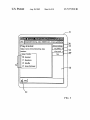
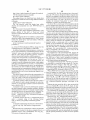
Selecting the play-mode link 35 (or play_mode-tab 34)
tree) as shoWn in FIG. 2.
A parameter <cmd> (or the last path-fragment) speci?es
pops up a WindoW 50 as shoWn in FIG. 5. Again, the user
50
The commands and parameters are transmitted on user
command, e.g., the user clicks the OK-button 52 on the CD
ny_cdpi990_mmoser_livingroom/cd_titles/add;BMW:
55
The above URL Would sWitch the play mode of the CD
player to “Normal”. Based on the protocol (here “bluetooth”)
the controller device’s communication stack recogniZes that
Wml_ui:<device_id>/ [<path>]/<command>[ ;<param
60
An example implementing this protocol is shoWn beloW:
menu
prede?ned service name (standardized) and sony_cdpi
990_mmoser_livingroom/main_menu
this is not a normal request, to be sent out via TCP/IP and the
Internet, but rather that this request must be intercepted and
forWarded to the local (bluetooth) communication stack.
The host speci?cation of the URL is then used to address
Wml_ui:sony_cdpi990_mmoser_livingroom/main_
Resource discovery is performed so a device may describe
its resources to its peers. In the above example Wml_ui is a
player play-modes WindoW 50 of FIG. 5, instructing the con
troller’s broWser to submit the folloWing URL, in example:
bluetooth://sony_cdpi990/playmode/select;Normal
To perform resource discovery, a communicating device
sends a command string in the folloWing format:
eters>]
selects from the different play modes by clicking on one of the
radio buttons 51 using the controller device’s input facility.
optional parameters of the above command. Examples imple
menting this protocol are represented beloW: bluetooth://so
Exodus bluetooth://sony_cdpi990_mmoser_livingroom/
play_mode/ select; shuf?e.
insert ?eld 41 using the input facility of the controller device,
e.g., a full-bloWn keyboard, pen-input, voice-input, or the
like.
a URL-<path>) is used to group commands into some tree
structure, e. g. if one looks at a printer’s menu-tree (execution
the actual command, While a parameter <params> describes
layout is displayed as WindoW 30 on the screen 31 of the
controller, as shoWn in FIG. 3. When, for example, the user
names”-tab 33, a card 40 to edit CD-titles is displayed, as
or physical location (eg “mmoser_livingroom'”)
A parameter <pre?x> (Which may have the same syntax as
is controlled by a controller having a display 31. The user
interface 30 shoWn contains a deck With only 4 cards: a
Welcome & overvieW card 36, a card to edit CD names 33, a
65
the speci?ed device (here a “Sony CD-player model 990”)
and the remaining URL-part (the optional path, the command
and the optional parameter(s)) are then sent to the speci?ed
device.
US 7,577,9l0 B1
13
14
The addressed device must have a simple “command-in
terpreter” that is able to recognize and execute received com
Ware interface 25. The device 70 may also have a user-inter
face unit 24 for interaction With a user (eg a small LCD
mands by analyzing submitted URLs, i.e. extracts and recog
display and some input keys).
niZes certain command strings plus optionally separates and
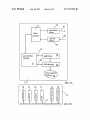
During remote access, user-interface information is sup
plied from a user-interface manager 71 to the MAC unit 72
converts parameters, etc. The complexity and robustness of
this interface is completely up to the manufacturers discre
tion, and therefore may vary according to manufacturer and
model number.
and transmitted to the (remote) controlling device via trans
mitter driver 73 and channel 81. User-interface information
The user may optionally receive a visual or audible con?r
mation When he/ she presses a button or clicks on a link and
With the more poWerful user-interface capabilities in order to
provide a superior user-interface to the controlled device for
thus “submits a request” to the controlled device. For this
reason the controlled device may react (this is an optional
step) and return some response to the submitted request, since
simply receiving a time-out message in the broWser With no
a user. Depending on the implementation, the user-interface
information may be information that describes a full user
interface (item 63 in FIG. 6).
success/failure indication Whatsoever is generally not su?i
cient.
Commands entered at the controlling device by the user are
received via channel 82 by the receiver driver 74 and for
The ?exibility, siZe, and complexity of this response is
completely up to the manufacturers discretion, the devices
capabilities, and resources. For example, the device may:
return data to display a speci?c card con?rming the reception
of the command and describing the results of its execution;
return data to display the complete user-interface-“deck”
Warded to MAC 72 and to user-interface manager 71. To
control the device 70 the user-interface manager 71 may
comprises any information needed by the controlling device
interface (see item 19 in FIG. 1), or describes a partial user
20
again With certain texts or default choices noW adapted
embodies a device’s purpose and/or functionality (be it a
video cassette recorder, a coffee machine, a printer, a stereo
according to the status changes caused by the previous com
mand; or return just a minimal OK, or error, page depending
on the command’s result. The user may then navigate back to
25
the control stack by pressing “return” in the broWser. Many
device, etc.). The actual activity or functionality of the device
70 is independent of the present design; using the present
design provides that this activity may be controlled and/or
monitored from another device.
Here, the MAC 72, the user-interface manager 71 and the
other responses or combinations of the above responses are
possible.
One exemplary implementation of the present invention is
communicate directly (item 83) or indirectly via an optional
application programming interface 79 (API) and a device
speci?c application 78 With hardWare drivers 26, and conse
quently With device speci?c hardWare 20 that provides and
30
application 78 are logical constructs. They may be imple
described in connection With FIG. 7A. FIG. 7A is a block
mented on separate devices or incorporated into a program
diagram illustrating the components, both logical compo
stored in memory 76. If incorporated into a program, the
device 70 may physically be the same as other devices, except
for the fact that it comprises the above-mentioned program.
nents and physical components, of a device 70 With a limited
user-interface. FIG. 7D illustrates building blocks of the hard
Ware layer. The device 70 comprises a transmitter driver 73
for sending information via an output channel 81 to another
device, such as a device With more poWerful user-interface
capabilities, and a receiver driver 74 for receiving information
35
The program comprises instructions that When processed by
40
the CPU 77, instruct the device 70 to perform the operations
necessary to implement the present invention.
The user-interface manager 71 exchanges the user-inter
face information, alloWing the user-interface to be provided
to the remote controlling device and control information and/
from other devices via input channel 82. The channels 81, 82
may be any kind of channels, such as an IR, RF, or body
netWork channels, for example. These channels do not have to
be the same. It is conceivable, for example, that the output
channel 81 is an infrared channel Whereas the input channel
82 is a RF channel.
The transmitter driver 73 and receiver driver 74 communi
45
cate With a medium access control (MAC) unit 72. The MAC
layer is Well de?ned by international standards (cf. ISO OSI
(Open Standards Interconnection) reference model as
described in A. S. Tannenbaum’s book “Computer Net
Works”, for example). The MAC unit 72 is preferably a con
ventional unit employed in communication systems to con
trol the MAC layer. Note that a MAC layer is a logical
ity periodically in step 84. This service announcement pro
cess may optionally run in the background, as indicated by the
dashed loop 8411. When the device receives information from
50
interface (UI) information; and user input. When the input
contains service information, then the received information is
55
used to update the device’ s oWn list of services in step 89. The
service information may be used by the second device to
transmit information about its capabilities. The service infor
mation is stored in a list for later retrieval. Alternatively, the
information may be retrieved only if needed, for example.
60
When the input is identi?ed to be a request to send user
interface (UI) information then the device sends its UI infor
mation to the second device in step 85. Finally, When the
information comprises a user input received from the second
poWer plug, a solar cell, a battery, or any other suitable means
Which are purposely left out for clarity.
With reference to FIG. 7D, the device 70 may comprise a
bus 21 enabling communication betWeen some of the
device’s components/units, such as the central processing
another device (second device), it categoriZes the information
into one of several categories. In the present example there are
three categories: service information; request to send user
division, and Would be only logically divided from other parts
of the protocol implemented at 71 on the same physical
device. The MAC unit 72 may be employed to detect and/or
avoid collisions betWeen transmitted data packets received
simultaneously from different devices. In the present embodi
ment the MAC unit 72 is used to send and receive packets. In
many cases, such a MAC unit 72 may not be required.
Device 70 and it’s components may be poWered via a
or parameters to be received from the device in response to
user input.
Referring noW to FIG. 8, a How chart is used to describe the
steps that are performed by a device 70 With a limited user
interface. The device 70 also transmits service information
(service announcements) to one or more devices Within vicin
device, then the device 70 processes and/or executes this user
65
input in step 86. In an optional step 90, a con?rmation signal
unit (CPU) 77, memory 76, the communication hardWare 22,
is returned to the second device to indicate to the user that the
23 and any other device speci?c hardWare 20 through a hard
controlled device processed or executed the command. Alter
US 7,577,910 B1
15
16
natively (see the dashed arrow at the lower right-hand side)
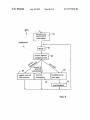
mation is not received, the controller device 700 returns to
the device 70 may, if instructed, send an entire or partial UI
background monitoring 102 to receive service information in
step 103.
description again Which is updated to re?ect results or status
In an alternative embodiment, the controlled device ini
tiates the process. In this case, the controlled device sends
user-interface information to a particular second device. If
there is a plurality of devices Within vicinity of the controlled
changes caused by the prior command. Finally, the device 70
returns to monitoring mode in step 87, and aWaits additional
information from the second device or any other device in
vicinity.
device, then the controlled device or the user selects one.
Before user-interface information is sent out, the device or
user may determine Whether there is another device in vicin
The embodiment described in connection With FIG. 8
implements a procedure Where the second device (i.e., the
device With a superior or more poWerful user-interface) trig
ity Which has the best user-interface. This may be done by
simply looking at the information stored in a list of available
devices in vicinity With corresponding services. If no list is
maintained, the controlled device transmits the user-interface
information hoping there is a device in vicinity Which is able
to receive and interpret the user-interface information. The
second device receives the user-interface information and
gers the device 70 With a limited user-interface to send user
interface information, Which may, for example, be initiated
When a user points the second device into the direction of the
computer device 70 With limited user-interface, or simply
brings the second device in vicinity of the device 70.
With reference noW to FIGS. 7B and 7C, an embodiment of
a controller device 700ii.e. a device that has a more poWer
provides a corresponding user-interface to the user. The user
then uses this user-interface to input information. The user’s
ful user-interfaceiis illustrated. FIG. 7B illustrates typical
logical and softWare-layer building blocks and FIG. 7C illus
trates building blocks of the hardWare layer. As shoWn in FIG.
73, the controller device 700 comprises a MAC protocol
20
feedback is returned to the second device to indicate to the
user that the controlled device processed or executed the
command.
handler 720, a transmitter driver 730, and a receiver driver
740 for communication With a remote device (not shoWn). In
addition, there is a user-interface manager 710 and a user
interface driver 750 to communicate With the user-interface.
As illustrated in FIG. 7C, the device 700 comprises a bus
706 (e. g. a back plane bus or a cable bus) for interconnecting
a transmitter 701, receiver 702, memory 703, CPU 704, and
user-interface 705 connected to a display and/or keyboard or,
25
An extension of the above described design is described
beloW With reference to FIG. 6. The user-interface source 67
and the command target 60 are separate, as illustrated in FIG.
6. The controlled device 60 does not necessarily have to
supply the entire user-interface description (Which could
30
pointing device, for example.
FIG. 9 is a flow chart illustrating the corresponding steps
performed by the controller device 700 during operation. The
controller device 700 background monitors 102 and receives
service information from a device With a limited user-inter
input is then sent to the controlled device Where the input is
processed and/or executed. In an optional step, con?rmation
35
become quite large4e.g. When lots of graphical elements are
employed) but only minimal required information. In this
case, the device 60 just sends a partial user-interface 63 (eg
a text-only version) via the Wireless communications path 66
to the controller 62, or the controlled device 60 supplies only
an initial user-interface description 63 (eg a URL) or
“pointer”.
face in step 103. If there is a plurality of computer devices
With limited user-interfaces (controllable devices) Within
The actual user-interface 65 or the additional information
vicinity of the controller device 700, then a list of these
controllable devices is displayed for the user in step 92. In
step 91 the user may also optionally request the list. The user
then selects a controllable device he Wants to control (con
trolled device) or interact With from the list in step 93. If there
is only one controllable device, or if the controller device 700
(eg graphics 69) are then retrieved from other locations, for
40
the illustrated example the actual user-interface is fetched
from a WWW server 67 using an HTTP request 64. This
otherWise knoWs Which controllable device the user Wants to
interact With, then steps 91-93 may be bypassed as indicated
45
device 60 itself.
controlled device responds by sending the requested user
Another, more complex user-interface implementation
alloWs the controlled device to implement only basic com
50
broWser equipped With some ?exible scripting language
Would, for example, automate tasks like the folloWing:
55
sponding commands are then sent back to the controlled
received from the controlled device and provided to the user
“CDDB”)
60
Copy the title and author of that CD into the title ?eld of the
CD-player’s User Interface and submit that request.
Start over.
predetermined period in step 100, the controller device 700
then aWaits additional user-interface information in step 101
for a predetermined period of time. If the additional user
interface information is transmitted the interface information
is received, returning to step 96. If the user-interface infor
Ask the user to insert a CD
Once a CD is inserted, request and display the current CD’ s
identi?cation code
Search that CD’s ID-code in a Web-based database (eg
device in step 99. A con?rmation signal may optionally be
(not illustrated in FIG. 9). The controller device 700 then
Waits for additional user input for a predetermined period of
time in step 100, returning to step 98 if additional user input
is received. If no additional user input is received during the
mands, using scripting techniques. These commands are
combined by the controller to form more poWerful compound
commands and also automate certain repetitive tasks. A
device in step 96, a corresponding user-interface is displayed
to the user in step 97. This may, for example, be done by
displaying the user-interface to the user, by reading text to the
user, by printing some information, etc. The controller device
700 then Waits to receive user input in step 98, and corre
alloWs the user-interface description 63 stored in the device
60 to be very small and only requires the implementation of a
simple command and parameter parsing capability in the
by arroW 94. Next, a request to send user-interface informa
tion is transmitted to the controlled device in step 95. The
interface information, as illustrated in step 85 of FIG. 8. After
the user-interface information is received by the controller
example, a ?le pre-installed on the controller or a WWW
server on the Internet, and combined into a uni?ed user
interface presentation 68 on the screen 14 of the device 62. In
Thus, the user simply inserts one CD after the other into a
65
CD-player (controlled device in the present example) While
the PC (controller device in the present example) searches
and automatically programs the corresponding CD-labels
into the CD-player.
US 7,577,910 B1
17
18
The present invention may also incorporate the translation
of user-interface controls. In this case, the controlling device
pointing device provided by the controller device to control
acts as a format translator, i.e. converts user-interface ele
pointing device.
ments to/from different formats or media. The controlling
The present invention may in part or as a Whole be imple
mented by or on a special computer device or a general
features of a device Which lacks such a mouse, pen, or other
device may, for example, provide speech synthesis and “read”
some text message to a vision impaired or occupied person
purpose computer device. This may be done by implementing
(e.g. during car-driving). Similarly, spoken commands to
the invention in some form of computer program. Computer
enter data into an input ?eld or activate a control-element (a
program in the present context means an expression, in any
language, code or notation, of a set of instructions intended to
cause a computer device to perform a particular function
either directly or after either or both of the folloWing:
spoken “button click”) may be converted. Such conversion
involves user-interface representation formats that do not
make any assumptions about the actual physical user-inter
face capabilities available in a device, but rather specify
a) conversion to another language, code or notation; and
b) reproduction in a different material form.
While the present invention has been described in detail
abstract functional levels of controls, e.g. WML does not
specify minimal display siZes in pixels nor require a mini
20
With reference to the preferred embodiments, they represent
more exemplary applications. Thus, it is to be clearly under
stood that many variations can be made by anyone having
ordinary skill in the art While staying Within the scope and
spirit of the present invention as de?ned by the appended
claims. Although speci?c terms are used herein, the descrip
tion uses terminology in a generic and descriptive sense only
25
and not for purposes of limitation.
The invention claimed is:
1. A method for controlling at least one ?rst device having
a limited user-interface by using at least one second device,
Wherein the ?rst and second devices communicate via a Wire
mum number of fonts to be available for menus and text
output, but rather speci?es “selection”, “input” and “activa
tion” capabilities. Menu-texts may eitherbe displayed or read
to the user and the user can type his/her ansWer or simply
speak to the device.
If a manufacturer relies on the fact that seldom used func
tions need not be controlled via a device’s front-panel but
rather using a better suited external device, the amount of
user-interface code for complicated, seldom used functions
can be drastically reduced, Which yields much easier, less
error-prone softWare development and consequently shorter
time-to -market and considerable price bene?ts due to quicker
development. A controllable device in accordance With the
less communication channel and support a common commu
nications protocol, the method comprising the steps of:
transmitting the limited user-interface information from
present invention is simpler and less expensive.
Given a minimal communication range (say 15-20 m), the
the at least one ?rst device to the at least one second
device to be controlled need not even be in the same room. It
could be in the basement or on the roof (e.g. heating, air
30
second device, the extended user interface having more
The standardized communication channel betWeen a con
extensive capabilities than the capabilities of the limited
trolled device and a controller can be extended (this technique
is usually knoWn as “proxy”) to alloW the bridging of larger
distances and to alloW remote-control and remote-diagnosis
device;
providing an extended user-interface on the at least one
condition, antennas, cable tuners, satellite receivers, etc.).
user-interface of the at least one ?rst device the extended
35
capabilities. For example, building and heating control might
user-interface utiliZing the transmitted limited user-in
terface information and comprising extended functions
require special knoWledge such that even a good user-inter
so as to extend the capabilities of the limited user-inter
face does not enable a customer to correctly adjust certain
face;
settings. By temporarily relaying the user-interface to a spe
cialiZed ?rm, some external specialist may con?gure or diag
accepting user commands input via the extended user
40
nose a remote system. Such World-Wide access to home
equipment is convenient for a “normal” user, too, because it
device; and
Will alloW the user to control home systems from a remote
location.
HTML can optionally be used as the exchange format. This
alloWs more ?exible, more poWerful user-interfaces but
Would be less elegant and compact than an WML implemen
executing the transmitted user commands on the ?rst
45
tation. Any other markup language may also be used.
prior to said ?rst device transmitting user-interface informa
50
an appointment from a PDA’s agenda to the doWnloaded
user-interface of a Wrist-Watch. The drag and drop capabili
interfaces, as Well as betWeen devices. If more than one
may act as an intermediate, i.e. one could drag and drop
information betWeen tWo controlled devices (eg copy a
phone number stored in a Wrist-Watch to a mobile phone).
55
Many of the bene?ts of the present invention become obvi
ous When reading the speci?cation. The present design alloWs
a user to make use of larger, better readable displays (e.g., a
larger color graphics display), superior/faster input capabili
ties (e.g., a full-?edged keyboard, or pointing device), and
ing-in data on a tiny numeric keyboard. According to the
present invention, the user may use a mouse, pen, or any other
the ?rst device and the second device.
5. The method recited in claim 1, Wherein the second
device comprises a display for displaying said extended user
interface.
6. The method recited in claim 1, Wherein the second
device comprises a keyboard for accepting the user com
mands.
7. The method recited in claim 1, Wherein a markup lan
guage is used for user-interface information.
8. The method recited in claim 7, Wherein Wireless Markup
Language (WML) is used as the markup language.
better suited l/O interfaces (eg a printer or audio system). It
is certainly easier to program a mobile phone or a Wrist-Watch
using a PDA or a computer screen and a keyboard than key
tion to said second device.
4. The method recited in claim 1, Wherein the Wireless
communication channel is automatically established betWeen
ties Work betWeen host-applications and doWnloaded user
device is currently controlled by the same controller, that host
device.
2. The method recited in claim 1, Wherein the user-inter
face information is a standardized user-interface description.
3. The method recited in claim 1, Wherein the second
device transmits a list of available services to the ?rst device
If the host-device (the controller) supports drag-and-drop
capabilities, this functionality may be exploitedieg. to copy
interface;
transmitting user commands from the second to the ?rst
9. The method recited in claim 1, Wherein the second
65
device provides the extended user-interface by using broWser
softWare to display at least a portion of the user-interface
information.