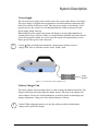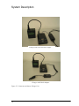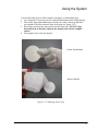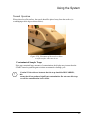
1
User‟s Manual Quantum Sniffer QS-H150 Portable Explosives Trace Detection System 2007 2007 by Implant Sciences Corporation All Rights Reserved The information contained herein is proprietary and is provided solely for the purpose of allowing customers to operate and/or service Implant Sciences Corporation manufactured equipment and is not to be released, reproduced, or used for any other purposes without written permission of Implant Sciences Corporation (Implant Sciences). Implant Sciences has made every reasonable attempt to ensure that the system is in optimum working condition. Failure to operate the equipment precisely as described in this manual may result in personal injury and void system warranty. Implant Sciences will not be held liable in instances of improper or unauthorized operation of equipment. Information and specifications in this manual are subject to change without notice. Quantum Sniffer, Implant Sciences and the Implant Sciences logo are trademarks of Implant Sciences Corporation. Throughout this manual, trademarked names may be used. Use of trademark symbols is not used in every instance as the names are used only in an editorial fashion, with no intention of infringement. The software contained in the Quantum Sniffer H150 system and accompanying materials are copyrighted. Unauthorized copying of the software, including software that has been modified, merged, or included with other software or the written materials is expressly forbidden without the prior written consent of Implant Sciences. All right, title, and interest in all copies of this software are and shall at all times remain the sole and exclusive property of Implant Sciences. Customer may be held legally responsible for any copyright infringement that is caused or encouraged by its failure to abide by these terms. DAFAR INTERNATIONAL INC. TEL:+886-2-2345-5738 FAX:+886-2-2345-5743 http://www.dafar.com.tw Contents Section 1: Before You Begin Warnings,Cautions & Notes ...................................................................................................................... Warranty Information ................................................................................................................................. Safety Summary ........................................................................................................................................ Typographic Conventions .......................................................................................................................... Entering Text ......................................................................................................... ............................... Press or Click ..................................................................................................................... .................. “Click” When No Mouse ........................................................................................................................ Press “ENTER”.................................................................. ................................................................... System Prompts or Messages .............................................................................................................. 2 2 3 4 4 4 4 4 4 Section 2: System Description Introduction ................................................................................................................................................ 6 Theory of Operation ................................................................................................................................... 6 Sampling Methods ..................................................................................................................................... 7 Vapor Sampling ................................................................................................................................ 7 Trace Detection: Non-Contact Sampling ................................................................................ 7 Trace Detection: Wipe Sampling................................................................................................... 7 Substances ............................................................................................................ ............................. 8 Standard Features .................................................................................................. .......................... 9 Physical Characteristics .......................................................................................................................... 10 Hardware Description .............................................................................................................. 11 Handheld Unit ...................................................................................................................................... 12 Power Supply ....................................................................................................................................... 13 Battery Charger Unit ........................................................................................................................... 13 Privilege Levels ........................................................................................................................................15 Operator Level (1) ...............................................................................................................................15 Supervisor Level (2) ............................................................................................................................15 Administrator Level (3) ........................................................................................................................16 Section 3: Using the System Powering Up the System ...................................................................................................................... 18 Using the Control Buttons ....................................................................................................................... 20 Warnings ............................................................................................................................. .................... 21 Humidity Too HIGH! ........................................................................................................................... 21 Low Charge ........................................................................................................................................ 21 Menus ............................................................................................................................... ...................... 21 Main Menu ......................................................................................... ................................................. 21 Main Menu Functions .......................................................................................................................... 23 Administrator-Level Menu Selections ................................................................................................. 23 Substances ............................................................................................................................. ....... 23 System Parameters .................................................................................... 24 Sampling Parameters ............................................................................................................. 25 i Contents Object Sensors ............................................................................................................ 25 SpectrometerCell ....................................................................................................... 26 Calibrant Parameters .................................................................................................. 26 Dopant Parameters .................................................................................................... 27 Hardware Status .......................................................................................................... 27 Alarm History .............................................................................................................................. 28 Spectrogram .......... ......................................................................................................... 29 Download Results ............................................................................................................ 30 Deep Cleaning ................................................................................................................ 31 Regeneration ................................................................................................................32 Taking a Sample: Step-by-Step .......................................................................................... 33 Non-Contact Mode ........................................................................................................ 33 Wiping Method: Transfer Sampling ................................................................................ 34 Taking a Sample Using the Wipe Method ..................................................................... 34 Analyzing a Sample Taken with Wipe Method ............................................................... 36 Results ................................................................................................................................ 37 Resolving Alarms ............................................................................................................ ... 39 Recommended Search Practices ...................................................................................... 40 Sampling Vehicles ............................................................................................................ 40 Sampling Cargo & Containers........................................................................................... 41 Sampling People & Personal Items .................................................................................. 42 Recommendations .............................................................................................................. 43 Calibration Verification .......................................................................................................... 44 Normal Operation ................................................................................................................. 45 Contaminated Sample Traps .............................................................................................. 45 Section 4: Operating in Desktop Mode Accessing the Interface Software ............................................................................................ 48 Using the Interface Software ................................................................................................... 49 Hotkeys ................................................................................................................................... 50 Adding & Editing Users and Password ................................................................................... 51 Selecting, Adding & Modifying Substances ............................................................................ 52 Selecting & Deselecting Substances .................................................................................. 52 Adding a Substance ............................................................................................................ 53 Modifying Substance Parameters ....................................................................................... 53 Performing a Manual Calibration ............................................................................................. 54 SysCheck Command ............................................................................................................... 54 Maintenance Menu .................................................................................................................. 56 Downloading Files ............................................................................................................... 56 Downloading Files; Alternate Method ................................................................................... 7 Upgrading Software ............................................................................................................. 59 Deep Cleaning...................................................................................................................... 59 Regeneration ....................................................................................................................... 59 ii Contents Save Options ....................................................................................................................... 59 Cleaning ............................................................................................................................... 60 History Menu ........................................................................................................................... 61 Section 5: Maintenance Recommended Maintenance Schedule ................................................................................... 64 Changing Sieve Material ..........................................................................................................64 ChangCalibrant ....................................................................................................................... 66 Recharging the Batteries ......................................................................................................... 68 Shipping Batteries.................................................................................................................... 68 Consumables and Spare Parts ............................................................................................... 69 Section 6: Troubleshooting Troubleshooting ....................................................................................................................... 72 Appendix – Material Safety Data Sheets ................................................................................. 77 iii Section 1: Before You Begin 1 Before You Begin Warnings, Cautions & Notes Several conventions used throughout this manual are described below. When a symbol is displayed, the user should carefully read the details accompanying the symbol to determine if precautions must be taken to maintain a safe work environment. ! text ! Indicates a WARNING! The warning symbol indicates that improper use or handling could cause personal injury and/or damage to the equipment. The following the symbol describes the specific warning and the precautions that should be taken by the user. Indicates a Caution. A caution symbol indicates that improper use or failure to execute a critical step may cause damage to the equipment. Indicates a Note of Interest. Notes are statements that either provide extra information about a topic or contain special instructions for handling a particular condition or set of circumstances. Warranty Information The system comes with a standard one-year warranty from date of shipment that covers parts and labor, return to factory. Extended service plans are available through the factory. Authorized personnel must install the Quantum Sniffer H150. The warranty or service agreement may be voided if the system is installed or serviced by unauthorized personnel. The standard training program included in the purchase of the equipment must be scheduled through the factory. This training covers typical hardware and software operation. The customer is responsible for training personnel on proper protocol when dealing alarms and alarm resolution. The customer is responsible for shipping charges when returning a system to the factory. The unit MUST be shipped in its original shipping case. Implant Sciences is not responsible for damages incurred from misuse (e.g. unit dropped). 2 Before You Begin Safety Summary To keep personnel safe during operation of the equipment and for optimum performance of the equipment, the following cautions and warnings must be reviewed and understood before operating the system. ! ! WARNING! The user must be familiar with established protocols on how to handle an actual threat. Personal safety is of utmost importance. WARNING! Do not perform maintenance or repair without authorization from the factory as it could damage the equipment, cause injury, and/or void system warranty. ! WARNING! Do not hold analyzer nozzle against skin or plastic bags as air blown from the nozzle during the sampling process can reach temperatures of 60C (140F). ! WARNING!The nozzle of the instrument is very hot. Do not touch any part. ! ! Caution! The system is sensitive to the operating environment. Smoking And spraying of aerosols should be avoided around the system while the system is in operation. Caution! Spare calibrant capsules may be provided with the system. These capsules contain potentially toxic chemicals. See the MSDS sheet in the appendix. Do not leave these capsules in an unsecured location where untrained personnel can accidentally handle them. See Maintenance section for disposal recommendations. ! Caution! See the safety warnings concerning the battery in the section titled “Power Supply and Battery Charger Unit”. ! Caution! Do not cover ventilation openings. ! Caution! When switching from internal to external power (battery or power supply) ONLY do so when the screen is in the “Ready” state. 3 Before You Begin Typographic Conventions Entering Text When instructions in the manual require the user to enter text by typing on the keyboard, the text will appear in bold letters as shown: bold text Press or Click When instructions in the manual require the user to press a system control button, a key on the keyboard, or select a button on the screen by clicking the mouse, the text appears in capital bold letters as shown: Press ENTER “Click” When No Mouse A keyboard and monitor can be attached to the handheld unit for administrator-level use. A mouse is not used with the H150 system. Whenever the instructions mention clicking the mouse, the keyboard equivalent is to press the TAB key until the desired command box is highlighted by a change in the lettering color. Then press the ENTER key on the keyboard. A shortcut hot key is also provided. See the HOTKEYS listed in Section 4. Press “ENTER” When only the handheld unit is present and there is no monitor or keyboard attached, the instruction “Press ENTER” refers to pressing the ENTER button on the control panel of the unit. System Prompts or Messages Messages or system prompts will displayed in italicized, bold font as shown: “Save changes? 4 Section 2: System Description 5 System Description Introduction The Quantum Sniffer™ H150 is a real-time, non-contact as well as wiping explosives trace detector. The spectrometry component of the detector is an Ion Mobility Spectrometer with a novel non-radioactive ion source utilizing Quantum Sniffer (QS) photon-ionization technology developed by Implant Sciences Corporation. The QS-H150 is designed to detect the presence of explosives molecules in air (vapor detection) or on a surface (trace detection) Theory of Operation The device will sample air surrounding the inspected object. Sampled air is injected into theQS ion source, ionized, and exhausted from the system. If an organic compound of interest is found, the system processes an “Alarm”. Explosives detection and identification is based on the measurements of molecular ion mobility within a drift tube. Sampled air is drawn into the QS ion source. The QS ion source is tuned to ionize specific classes of organic molecules. After pulsed ionization, ions start their journey to the collector, pulled or drawn by an electrical field within the drift tube. Small ions arrive earlier, the larger ions move slower and arrive at the collector later. Every molecular ion has its signature in the arrival time, which allows us to identify the nature of detected ions. See Figure 2-1. Figure 2-1: System Schematic Cross Section 6 System Description Sampling Methods Vapor Sampling When used as a vapor detector, the handheld unit should be placed in the vicinity of the suspected threat. It should be taken into consideration that the device is capable of detecting explosives vapors down to volume concentrations of parts-per-trillion (ppt) in air. Equilibrium vapor pressures of such explosives as NG and TNT are much higher and their vapors will be detected even when diluted in air. Vapors of some low vapor pressure explosives, such as RDX, PETN, and HMX, can be detected if they were accumulated in a closed volume for some period of time and presented to the detector for analysis without diluting. This is dependant on ambient temperature. To detect vapors of low vapor pressure explosives, the inspected container or compartment should be slightly open – only enough to sample concentrated vapors from the inside, but not opened enough to allow outside air to dilute accumulated vapors. Trace Detection: Non-Contact Sampling When used as a trace detector, the sampling intake of the handheld unit must be placed above the inspected surface. When the START button on the Analyzer Unit is pressed, the vortex generator will blow warm air to the inspected surface and stimulate vapor release from explosives trace residue. At the same time the heated vortex creates a small artificial tornado above the surface and picks up vapors released by an explosive‟s trace and transport them into the device‟s ion source. Both functions, vapor detection and trace detection, are realized in one explosives detection system regime, activated by pressing the START button on the handle. If explosives molecules are detected, the system will process an “Alarm”. If no substance is detected, the system will display a “No Substance Detected” message and within 3 seconds will be “Ready” for the next analysis. Trace Detection: Wipe Sampling When used as a wipe detector, the sample is obtained by wiping a surface with an approved paper sample trap. See Section 3 for recommended wiping methods. The paper trap held within 1-2cm of the detection head for sampling. The operator presses the START button. The system vaporizes the material on the sample trap and if a target substance is detected, the Alarm is displayed on the screen, and a blue light emitting diode (LED) is illuminated. If no substance is detected, the system will display a “No Substance Detected” message and within 3 seconds will be “Ready” for the next analysis. If an explosive is detected, the used paper trap should be disposed of according to the user‟s standard protocol, possibly retaining the trap for forensic evidence if required for an alarm. If there is no alarm, the trap may be reused a number of times, depending on the environment. 7 System Description Substances The system is calibrated at the factory for the substances listed in Figure 2-2. Additional substances can be added. Contact factory for details. Substance NC Ammonium Nitrate RDX (C-4 component) PETN (SEMTEX component) NITRO1 NITRO2 RDX1 RDX2 PETN1 PETN2 PETN3 Nitroglycerin (Dynamite component) NG Black Powder BP TNT TNT DNT (Taggant) DNT TETRYL TETRYL HMX HMX EGDN EGDN Figure 2-2: Substance List 8 Substance ID System Description Standard Features The QS-H150 System consists of the following standard features: Simple-to-use software with 3 access levels for security purposes Non-contact analysis Wiping mode analysis using sample traps Automatic system self-calibration and self-cleaning 2 rechargeable batteries, each with up to 4-hour capacity Battery recharging unit Universal AC power supply 100/240VAC, 50-60Hz with 10 foot (3 meter) cable for operation with AC power source Audible and LED alarm indicators (audible indicators can be disabled) Audible proximity sensing indicator (audible indicator can be disabled) Built-in CPU and analysis software USB flash disk for easy data download Internal calibrant and optional reactant systems Durable waterproof transport case with low-profile wheels and retractable handle Verification sample User‟s manual 9 System Description Physical Characteristics Warm up Time: 15 minutes from „switch Operating Temperature: -10-50C (14-122F) Relative Humidity: 0-95% non-condensing Environmental: IP52 Rated Input Power: 12-15 VDC, 4-hour rechargeable battery 100-240VAC, 47-63Hz, 4A (max) via provided universal power supply Computer: Pentium-Based PC104 with built-in memory Analyzer Unit Display: 3” (7.5cm) Graphic LCD, 128 x 64 Analyzer Unit Dimensions: L 19¼” (49cm) x W 5” (13cm) x H 7½” (19cm) Analyzer Unit Weight: 9½ lbs (4_kg) (without battery installed) Power Supply Cable: 6 ft (1.8 meters) Non-Contact Sensitivity: Vapors- ppt (parts per trillion) Particles- < 20ng from 1cm distance (dependent on surface) Selectivity: 1% typical false-positive rate Sampling & Analysis Time: 12 seconds (default); 5-30 seconds (user variable) Cleardown Time: 14-16 seconds for most alarms Air collection for vapor Non-contact collection for trace particles via unique „tornado‟ (vortex) sample acquisition system. Particle collection by wiping surface with Sample Acquisition: sample trap Non-Contact Sampling Distance Particle: ½” to 2” (1 to 5cm) Vapor: concentration-dependent Sample Flow: 10 6ml per second System Description Hardware Description The major components of the system are described below. START BUTTONS BATTERY ACCESS CONTROL BUTTONS LCD DISPLAY PROXIMITY LED CALIBRANT ACCESS NOZZLE (SAMPLING AREA) Figure 2.3: Major Components of H150 System ON/OFF Figure 2-4: Rear Panel Connections 11 System Description Handheld Unit The Handheld Unit contains a built-in computer and analysis software. It has a backlit LCD screen that displays simple software screens that prompt the user through an analysis. This analysis begins by simply pressing the START button on the handle when the system displays a “Ready” message. The control buttons allow the user to maneuver through screens to set operating preferences and perform various functions. The Handheld Unit also contains connectors that allow an administrator-level user (or higher) to connect to a monitor and keyboard to access more in-depth analysis screens and functions. Additionally, the Handheld Unit contains an array of LEDs that indicates the status of the system; BLUE:: indicates an “Alarm” CONSTANT GREEN: indicates that system is “Ready” to take next sample BLINKING GREEN: indicates system is “Sampling” YELLOW: indicates that user must “Wait” YELLOW/GREEN: when system has been inactive for a period of time, the system goes into “Standby” mode, indicated by the slow blinking back and forth of YELLOW and GREEN LEDs. Standby occurs only when operating in battery mode. BLUE/GREEN/YELLOW: all 3 LEDs randomly blinking indicates that the system is booting up or that there may be a hardware or software problem WARNING!In cases of an alarm condition, the user must be familiar with ! applicable protocol on how to handle an actual threat. Personal safety is of utmost importance. 12 System Description Power Supply The universal power supply can be used to power the system in the absence of a battery. The power supply is plugged into an appropriate wall outlet and then connected to the back of the system via the power cable. Once the power supply is switched on, it will provide power to the system. It is recommended that the system be powered by the power supply during warm-up. When using the power supply, the system will display a message indicating that an external power source is in use. If there is a charged battery installed in the unit, and the system is being used with the AC power cord, the system will automatically revert to battery power if the power cord is removed. ! Caution!When switching from internal to external power (battery or power supply) ONLY do so when the screen is in the “Ready” state. POWER SUPPLY SUPPLY TO AC OUTLET Figure 2-5: Connection to Power Supply Unit Battery Charger Unit The battery charger and associated cables are used to charge the lithium ion battery. The charger can be powered using either the charger unit AC line cord or the charger unit vehicle adapter. Please refer to the Maintenance section for details on hooking up the charger components. Charge time for a depleted battery is 8 hours. ! Caution! When charging batteries, use only the cables provided with the battery charger unit to power the charger. 13 System Description Charger with Universal Power Supply Charger with Vehicle Adapter Figure 2-5: Connection to Battery Charger Unit 14 System Description Privilege Levels For security purposes, there are 3 privilege levels; Operator, Supervisor, and Administrator.Listed below are the software functions that each user-level can exercise. Operator Level (1) Log on/off Time/Date setup/confirmation Calibration Cleaning Alarm acknowledge/resolution Backlight enable/disable Audible alarm enable/disable Alarm LED enable/disable Proximity sensor audible indicator enable/disable Supervisor Level (2) Log on/off Time/Date setup/ confirmation Calibration Cleaning Alarm acknowledge/resolution Backlight enable/disable Audible alarm enable/disable Alarm LED enable/disable Proximity sensor audible indicator enable/disable Edit passwords Select substances & change alarm levels Deep cleaning & regeneration Add/Delete users 15 System Description Administrator Level (3) Log on/off Time/Date setup/ confirmation Calibration Cleaning Alarm acknowledge/resolution Backlight enable/disable Audible alarm enable/disable Alarm LED enable/disable Proximity sensor audible indicator enable/disable Add/Delete users Edit passwords Select substances & change alarm levels Deep cleaning & regeneration Edit substance parameters Add substances Download files Update software 16 Section 3 Using the System 17 Using the System Powering Up the System Note:These instructions assume that the appropriate personnel have been trained. 1. Ensure that the system battery is properly installed or that the system has been plugged into an appropriate power source. 2. Turn the system power ON by using the power switch on the rear of the unit. 3. The system will display an “Enter Password” prompt. Using the SCROLL control button, highlight each digit of the PIN number, pressing the ENTER button after each selection. 4. When finished entering the PIN number, SCROLL to highlight DONE, and press ENTER。 When shipped, the unit contains an administrator-level default password 1914. ! Caution!This is an administrator-level password and must be changed immediately! The administrator is responsible for logging onto the system with the default password, changing it, then adding users as described in the section titled „Adding and Editing Users and Passwords‟. Note that the system MUST be attached to a display and keyboard to accomplish this. ISC QS-H150 Explosives Trace Detector ENTER PASSWORD **** 0 1 2 3 4 5 6 7 8 9 Done Figure 3-1: Log In Screen 5. The system will display a “Date/Time” verification message. The user must verify the correct date and time and then press ENTER. If the date or time is incorrect, the user must follow the screen prompts to change them. 18 Using the System 6. The system will then display a “Warming Up” message along with a status indicator of time remaining. The system‟s YELLOW LED will flash during this time, indicating that the user must wait. 1:56 PM EXTERNAL WARMING UP… TIME REMAINING 14:37 Figure 3-2: Warming Up Screen 7. Once warmed up, the system will automatically perform a calibration. During the calibration, the LED on the system will be YELLOW, indicating that the user must wait. If the calibration fails, all of the LEDs will blink, indicating the calibration has failed. Please follow troubleshooting instructions for failed calibration (see Troubleshooting section). During the warm up period, an Administrator can access the various menu functions and perform operations other than sampling. When system is ready, it will display a “Ready” message and the GREEN LED will illuminate on the Analyzer Unit. Note:When system is powered using the power supply, „EXTERNAL‟ will display in the upper right-hand corner of the screen. When the system is powered with the battery, „BATT‟, along the battery power-level remaining will be indicated in the top right-hand corner of screen. 19 Using the System READY BATT Push START for Analysis, SCROLL for Menu/LOGOFFSCROLL MENU LOGOFF Figure 3-3: Ready Screen Using the Control Buttons Located just below the display screen, the control buttons allow the user to maneuver through different menus and carry out various functions. The level of access is dependant on the user level. Mo SCROLL Moves the cursor up through each of the menu selections. Also scrolls through additional menus when available. Increases numeric values (alarm level, sample time, etc.). Can also be used to scroll through Menu selections. Decreases numeric values (alarm level, sample time, etc.). Can also be used to scroll through Menu selections. ENTER 20 Carries out highlighted function. Using the System Warnings Various warning messages may appear on the screen indicating possible faults or less thanoptimal operating conditions. The most common messages follow. Humidity Too HIGH! The air-drying molecular sieves may need to be replaced. See Section 5. Low Charge The system‟s ion source may require regenerating. See “Regeneration” in the Menus section below. Menus The following describes the various menu functions that can be accessed using the control buttons. To access the menu, from the „Ready‟ screen, press the SCROLL button. Main Menu To access any of the menu items, use the SCROLL button to navigate through the menu items and highlight the item of choice. Once highlighted, press ENTER to access the field. Use the ARROW buttons to make changes. Note:Once changes are made to a given field, it is necessary to press the ENTER button for the changes to take affect. To gain access to the previous or next menu, UP and DOWN arrow keys. Use the SCROLL button to highlight the menu selection. Once highlighted, press ENTER to access the selected menu. \ prev Dist Audio ON Calibrate Back Light ON Clean Alarm Audio ON Turn ON Crevice Mode Alarm LED ON Figure 3-4: Main Menus 21 Using the System Administrator-level users have access to additional menu functions as described below. Substances System Parameters Hardware Status Alarm History Spectrogram Download results Deep cleaning Regeneration Allow Logon ON Software upgrade Save Options Language Figure 3-5: Administrator-Level Menu Selections 22 Using the System Main Menu Functions Calibrate: Forces the system to calibrate itself (manual calibration). Although the system automatically calibrates at predetermined intervals, a user may want to initiate a calibration sequence. Clean: Initiates a clean sequence. Again, the system cleans itself at predetermined intervals, but the user may choose to initiate a clean sequence. Crevice Mode ON/OFF: The Crevice tool is an optional tool that allows the user to sample in small crevices. This mode must be turned ON when the Crevice tool is attached. When this option has not been purchased, the menu selection is grayed out and cannot be selected. Distance Audio ON/OFF: Turns ON or OFF the audio on the proximity-sensing device. Backlight: Turns ON or OFF the graphic display backlight. Alarm Audio: Turns ON or OFF the alarm audio. Turning off the audible alarm might be used when trying to detect explosives in a more covert manner. Alarm LED: Turns ON or OFF the blue alarm LED. Turning off the alarm LED might be used when trying to detect explosives in a more covert manner. Administrator-Level Menu Selections Substances Allows Administrator-level user to select/deselect substances and change alarm levels. When selecting substances, it is important to keep in mind that some substances contain more than one peak. The user can select each peak individually in the „SP‟ column. This means that the system will alarm if any of the peaks are detected. However, if the user wants the system to alarm ONLY when BOTH peaks are present, they must place an * in the „DP‟ column next to the substance peak. When substances are selected, SP means single peak alarm is selected and DP means dual peak alarm is selected. 23 Using the System Note:Please note that only a representative selection of substances is shown in the figure below. There are many other substances in the library that can be selected and changed. Subst SP DP Calibr Ampl 1000 NITRO * 3000 RDX * 250 TNT * 250 Figure 3-6: Select Substance & Change Alarm Level Screen System Parameters Allows Administrator-level access to a secondary menu where various system parameters can be viewed and changed. prev Calibrant Sampling Parameters Dopant Object Sensors prev Spectrometer Cell Figure 3-7: System Parameters Menu Screens 24 Using the System Sampling Parameters View and edit the parameters of the Sampling System instrumentation. A RESTORE DEFAULTS feature is available to reset all system parameters to the factory settings. ! Caution! It is recommended that these settings be kept at the factorydefault levels. Changing any of these parameters could render the system inoperable. Contact Factory for instructions before editing these parameters. prev 15 Stand By Time Sampling Time, sec 12 Sampling Air Flow 80 Vortex Air Flow 90 Vortex Heater 80 Vortex Heater Idle 20 prev Figure 3-8: Sampling Parameters Screens Note: Values shown are for illustration purposes only and may not represent actual default values. Object Sensors Allows the user to change the parameters of various sensing devices. Prev Distance Min, cm 0 Distance Max, cm 5 Figure 3-9: Object Sensors Screen Note: Values shown are for illustration purposes only and may not represent actual default values. 25 Using the System Spectrometer Cell Allows the user to view the status of the ion mobility spectrometer and change critical component parameters. prev High Voltage 2371 Source Power 100 Sieves Air Flow 80 Figure 3-10: Spectrometer Cell Screen Note: Values shown are for illustration purposes only and may not represent actual default values. Calibrant Parameters Allows the user to view the status of the calibrant unit and change the calibrant temperature. prev CAL Ampl CAL Pos 3126 33.2ms Last 10/08/07 13:36 Set CAL Temp 70 CAL Temp Status 70 RESTORE DEFAULTS prev Figure 3-11: Calibrant Parameters Screen Note: Values shown are for illustration purposes only and may not represent actual default values. 26 Using the System Dopant Parameters If dopant is used, allows the user to view the status of the dopant (reactant) unit and change the reactant temperature. prev Set Dopant Temp 0 Dopant Temp Status 0 Figure 3-12: Reactant Parameters Screen Note: Values shown are for illustration purposes only and may not represent actual default values. Hardware Status The Hardware Status screen displays the status of the various components of the system. These are status indicators and cannot be changed. prev NozAir_1 not active PrSensT 45 (45) Press START to quit Figure 3-13: Hardware Status Screen 27 Using the System Alarm History The Alarm History screen allows the user to scroll through and view alarms that have been automatically saved on the system‟s computer. From this screen, the user can also view the alarm in spectrogram format as shown in the figure below. The alarm spectrogram displays the time (in ms) and level of the alarm. To view the alarm spectrogram, from the Alarm History screen, press SCROLL. To exit the Alarm Spectrogram screen, and go back to the Alarm History screen, press SCROLL. To exit the Alarm History screen, press ENTER. 10/01/2007 15:17:23 Subs detected: TNT Peak:33.23 (32.93-33.43) Ampl:1168 ((level 250) Cal:10/01/07 15:15:49 Figure 3-14: Alarm History 1145 33.12 Figure 3-15: Alarm History & Alarm Spectrogram Screen 28 Using the System Spectrogram The Spectrogram screen allows the user to view data (whether alarm or other) in spectrogram format. Use the SCROLL key to move the X-axis across the screen to display the time (ms) and level at any given point in the peak. Use the ARROW keys to change the vertical (amplitude) scale of the graph. To exit the Spectrogram screen, press ENTER. 145 19.00 LEVEL TIME X AXIS Figure 3-16: Spectrogram Screen 29 Using the System Download Results Download files to a USB stick that have been saved in the system‟s internal memory.Insert a USB drive into the socket on the I/O panel and press START when instructed. Are you sure you want to download results onto USB stick? (30 MB required ) Press START to confirm, any other key to quit Insert USB stick, Press any button, Wait for READY Start Downloading Downloading AL061011 41% Done Figure 3-17: Download Screen 30 Using the System The system reboots the internal computer in order to properly recognize the USB stick and executes a separate program for the download. During that process, the small screen will go blank briefly, and the fans in the Analyzer unit will stop. During downloading, the green and blue LED‟s will blink. When the download is complete, the main Analyzer program is restarted automatically from the beginning. ! Caution! Files are erased from the internal computer disk when they are downloaded. The only copy is now on the USB stick. Exceptions to the normal download sequence occur when: 1. No USB stick has been inserted. Message: NO USB STICK! Press ENTER to clear the message. The system will reboot. Start a new download. 2. There is not enough space on the USB stick. Message: NO ROOM! Press ENTER to clear the message. The system will reboot. Start a new download with a USB stick that has sufficient space to receive the download. Deep Cleaning The Deep Cleaning feature allows the administrator to perform a deep cleaning of the system. A deep cleaning cycle increases the sample path heater temperatures for a pre-set amount of time to burn off contamination that may have accumulated during extensive usage or from a strong alarm. Note: Prior to performing a deep cleaning, the system should be plugged into an AC power source. Do not perform deep cleaning using battery power, as this will deplete the battery. Press START to begin DEEP CLEANING other key to quit Figure 3-18: Deep Cleaning Screen 31 Using the System Regeneration The Regeneration feature allows the administrator to perform a mirror regeneration cycle. A mirror regeneration will increase the temperature of the ion source window. This will bake off contamination that may have built up on the window. This function should be used when a “Low Charge” warning appears on the display. Note: Prior to performing a mirror regeneration cycle, the system should be plugged into an AC power source. Do not perform regeneration using the battery power as this will deplete the battery. Note: It is not possible to interrupt the regeneration process except by rebooting the computer. Press START to begin MIRROR REGENERATION other key to quit Figure 3-19: Regeneration Screen 32 Using the System Taking a Sample: Step-by-Step Non-Contact Mode The non-contact sampling method is used where there exists the possibility of finding vapor from a concealed or confined explosive source. It is also used to search for explosive residue or surface contamination generally left behind in the form of fingerprints by someone who has handled, or come in contact with explosives. The following steps are for taking a sample in non-contact mode: 1. Verify that the GREEN LED is on (not flashing), and that the system is displaying the “Ready” screen. 2. Press the green START button. The green LED will begin flashing, indicating that the system is ready to begin the sample once the proximity sensor is interrupted. You have 15 seconds to begin sampling once the LED starts flashing. 3. Slowly move the sample nozzle towards the sample target. Once the correct sample distance has been sensed, the system will automatically begin sampling. Hold the nozzle above (½” – 2” inches or 1 to 5cm) the target area for the duration of the sample, typically 12 seconds. 4. If there is no alarm and the sampling is complete, move the nozzle away from the surface and prepare for the next sample. The display will show “Ready” when the next sample may begin. Typical system responses for an alarm or no-alarm condition appear in the following section (see Figure 3-24). Figure 3-20: Non-Contact Sampling Wiping Method: Transfer Sampling 33 Using the System The wiping method involves collecting, or transferring the sample onto a paper sample trap and then analyzing the trap, using the non-contact method. Use sample traps and the wiping method when the following conditions exist: Surfaces, such as metallic surfaces, that are difficult to heat Surface, such as plastic and synthetic fabrics, that could potentially be damaged by heat Restricted access surface where the system can not physically fit Extremely cold environments where the sample can be brought to the instrument that is located in a climate-controlled area Large surface areas that need to be searched in a short period of time Taking a Sample Using the Wipe Method Explosive compounds can be detected on a variety of surfaces, e.g. clothing, luggage, packages, vehicles, etc. Using a sample trap is an effective way to search quickly. Many types of paper and cloth can be used for collecting samples, however, Implant Sciences recommends the use of sample traps provided with the instrument, as they are contaminant-free. If you choose to use a locally sourced paper trap such as a paper towel, it is recommended that you run several samples of the paper and then test the verification sample (also provided with the instrument) to ensure that the instrument sensitivity has been maintained. If false alarms occur as a result of sampling the intended paper, or if the instrument fails to produce a TNT alarm when analyzing he verification sample, DO NOT USE that particular paper type. Keep trying different papers until one is found that will not produce false alarms and does not prevent detection of the verification sample. Once a reliable paper source is identified, use only that particular type of paper. Sample traps may be used several times unless they have collected a substance that produces an alarm, have been torn or shredded, or have become excessively dirty or oily. Any of the conditions mentioned would be cause to discard the sample trap and use a new one. If the paper trap should become wet during sampling, it should be allowed to dry before being analyzed. 34 Using the System Use the following steps to collect samples with paper or cloth sample traps: 1. Use clean gloves to prevent excessive hand contamination from soiling the trap. 2. Place index finger and middle finger onto the top center of the trap and allow your thumb to hold the underside edge of the trap (see Figure 3-21). 3. Press firmly and wipe the target area in one direction only. DO NOT wipe back and forth as this may redeposit the sample back onto the sampled surface. 4. The sample is now ready for analysis. Proper Trap Handling Wiping a Surface Figure 3-21: Sampling with a Trap 35 Using the System Analyzing a Sample Taken with Wipe Method Use the following steps to analyze samples taken by the wipe sampling method: 1. Verify that the GREEN LED is on (not flashing), and that the system is displaying the “Ready” screen. 2. Press the green START button. The green LED will begin flashing, indicating that the system is ready to begin the sample once the proximity sensor is interrupted. You have 15 seconds to begin sampling once the LED starts flashing. 3. Position the sample trap approximately ½” – 2” inches or 1 to 5cm under the sampling nozzle, ensuring that you pass over the proximity sensor to begin the sample. Ensure that the portion of the trap where the sample was collected is positioned directly under the sampling nozzle. 4. Continue to hold the trap in this position until the sample is complete (Ready screen will be displayed) or an alarm is produced. 5. Upon alarm, or when the sample is completed, immediately remove the trap from the sampling area. 6. If an alarm is produced, or the sample trap is dirty or torn, discard the trap and use a new one for the next sample. Typical system responses for an alarm or no-alarm condition appear in the following section (see Figure 3-24). Figure 3-22: Analyzing a Sample Trap 36 Using the System Results The following is a list of possible results and messages that may appear on the unit: LED Color Description Result BLUE ALARM Follow alarm protocol GREEN NO ALARM System ready for next sample WAIT System may be self-calibrating or self-cleaning. Wait for „Ready‟ screen. FAILURE System Hardware or software has failed. Contact appropriate personnel. YELLOW BLUE/GREEN/YELLOW If the system alarms, an alarm screen displays similar to the one shown below. To clear the alarm, press the START button. To view the alarm details, press ENTER. From the „Alarm Details‟ screen, press ANY BUTTON to continue to the „Ready‟ screen. Substance Detected 10/10/2007 09:52:33 TNT Subs Detected:TNT TNT !! Push START to go on, ENTER for alarm details Peak:: 33.39) 32.98 (32.89- Ampl: 1375 (level 250) Last Cal: 10/10/07 09:35:02 Figure 3-23: Example of Alarm Screens The screen on the right is reached by pressing the ENTER key. 37 Using the System Typical Non-Alarm Sequence Typical Alarm Sequence 1:56 PM 1:56 PM BATT READY Push START for Analysis BATT READY Push START for Analysis _______________________ ▼Menu _____________ ▼Menu 1:56 PM BATT SAMPLING . . . Continue to hold over surface 1:56 PM BATT SAMPLING . . . Continue to hold over surface Substance Detected RDX 1:56 PM 1:56 PM BATT BATT ! ! ALARM ! ! RDX DETECTED Press START to Continue. ANY KEY to View Details NO ALARM Wait for Ready 1:56 PM READY BATT Cleaning Attempt 1 READY Figure 3-24: Typical Sample Sequences 38 Using the System Resolving Alarms WARNING! In cases of an alarm condition, the user must be familiar with ! company protocol on how to handle an actual threat. Personal safety is of utmost importance. When an alarm occurs, the system will display an alarm condition, and the blue LED will illuminate (unless disabled). Additionally, if the audible alarm is enabled, an alarm will sound during an alarm. The system will automatically save the alarm file to the removable USB flash disk (when installed). When the USB disk is not installed, the alarm file will be saved to the system‟s hard drive. All alarm files are saved with all system conditions recorded. To resolve an alarm condition, the user must FIRST FOLLOW ESTABLISHED PROTOCOL FOR ALARMS. After following established protocol, the user presses the START button to clear the alarm. To view alarm details press ENTER. From the „Alarm Details‟ screen, press any button to continue to the „Ready‟ screen. 39 Using the System Recommended Search Practices The tables in the following sections indicate the areas that should be sampled and the recommended sampling methods that should be used to collect samples. Sampling Vehicles Search Article Non-Contact Method Trunk space X Trunk articles, parcels, luggage, etc. X Door handles, mirrors, steering wheel, controls, seat fabric X X Heat/AC ventilation, air fan ON switch X Speakers, stereo ON switch X Glove box or other compartments X Engine compartment X Non-Contact Method Wipe Sampling Method X Wipe Sampling Method Figure 3-25: Sampling a Vehicle ! 40 Caution! When searching for vapors, use care to keep the vapors from escaping. Opening doors and trunks just a very small amount when starting a sample cycle and holding the nozzle very close to the opening will increase the probability of detecting vapors Using the System Sampling Cargo & Containers Search Article Container openings, inspection ports, cracks, gaps, seams Non-Contact Method Wipe Sampling Method X Door latches, handles, locks X Contents- well sealed X Contents- possible opening exposed X Palletized items wrapped in plastic Loose items X X Non-Contact Method X Wipe Sampling Method Figure 3-26: Sampling Cargo & Containers ! Caution! When searching for vapors, use care to keep the vapors from escaping. 41 Using the System Sampling People & Personal Items Search Article Wipe Sampling Method Hands X Clothing- pockets, buttons, belts, shoes X Purses, carry bags, brief cases (seams, handles, latches) X X Eyeglasses, pens, keys X X X WARNING! Do not hold analyzer nozzle against skin as air blown from the nozzle during the sampling process can reach temperatures over 60C (140F). Non-Contact Method Figure 3-27: Sampling People and Personal Items 42 X Identification- license, passport, manifest Currency and coins ! Non-Contact Method Wipe Sampling Method Using the System Recommendations In the case of a positive alarm situation follow the alarm resolution guidelines as dictated within your policy and procedures manual. It may be necessary for legal purposes to label and retain traps that produced an alarm condition. It is the user‟s responsibility to be prepared to accomplish this according to his organization‟s policy and procedures. A suggested sealable holder is a static free plastic container of the type used for electrical circuit boards. It is recommended that the user should verify that a new blank trap does not produce an alarm after an alarm event has occurred to avoid accidental false alarms because of residual contamination within the instrument. Trap material, other than the paper traps supplied by ISC, may only be employed in special circumstances and ISC cannot guarantee that any given trap material will be consistently effective. A few requirements need to be considered before using a paper towel or napkin to wipe a surface. Cleanliness is absolutely important. A sample trap has to be clean to the instrument, not simply “white”. The paper sample trap should have a slight texture or abrasiveness. Ideally, the perfect trap doesn‟t change the spectra at all. It is not recommended that one vigorously wipe surfaces. The heat generated by the friction of rubbing can actually cause the microscopic quantities of explosives to decompose. This is more important for the more volatile substances, such as nitroglycerine, TATP and HMTD. A sample trap may exhibit small clean tears, but a heavily ripped trap should not be used. Minute pieces of trap material, possibly contaminated, may be drawn into the sampling region. This can cause an alarm, and the lint may become lodged in the sampling line, making clear down difficult. In addition, if the trap is reused after being contaminated earlier with an explosive or a contaminant, continued false alarms may occur. Personnel associated with the operator may be “hot”, because they work around explosives and unknowingly have become contaminated. In turn, these individuals may further contaminate the work area and be the source of “false” alarms. It can not be overemphasized that the operator most likely successful in finding a true positive will be the one that recognizes the locations that people will likely be touching and uses good wiping technique to obtain the sample. 43 Using the System Calibration Verification Users can verify that the system is working properly by taking a sample with the Verification Sample provided with the system. To do this, with the system „Ready‟, press START. Open the Verification Sample and hold it close to the nozzle, ensuring that the can is passed over the proximity sensor, as shown in the figure below. The system should alarm. If the system does not alarm to TNT, repeat this process, making sure the Verification Sample is held no more than 1 inch from the nozzle. If the system still does not alarm, contact a Supervisor or Administrator for help. Figure 3-28: Calibration Verification Normal Operation 44 Using the System Normal Operation When placed on a flat surface, the nozzle should be placed away from the surface (i.e. overhanging a table edge as shown below). Figure 3-29: Placement of the nozzle relative to a flat surface when not in use Contaminated Sample Traps If the trap contained large amounts of contamination, the display may instruct that the START button be pushed again to initiate an automatic cleaning cycle. ! Caution! If the software instructs that the trap should be DISCARDED , this means that it has produced significant contamination. Do not reuse this trap, even if the contamination is not visible. 45 Using the System A sample trap may be reused as many times as desired provided; a) b) c) d) it is not physically damaged by tears or holes, it is not highly contaminated as indicated by the DISCARD TRAP message on the display, the trap is not so loaded with visible spurious material that it is spreading contamination between locations, and the surface of the trap is still rough enough to reasonably collect a sample. It is not unusual for traps to be reused as many as 10 times in fairly clean environments. However, in a shipboard situation where sample-collecting locations are more likely to be contaminated by oil, as few as 1-2 uses may be more normal. The software will attempt up to a preset number of cleaning cycles if the system is identified as being contaminated. If these cleanings are successful, the display will indicate „Ready’. If the unit has failed to clean, the operator may choose to perform manual cleaning, which is initiated on the menu screen shown in Figure 3-4 by selecting CLEAN. It is recommended that this is the best method for most situations, since all operators can access it. A stronger cleaning procedure is to turn on DEEP CLEANING in the administratorlevel menu. This heat cleaning process requires about 30 minutes to complete and is usually successful at removing any contamination in the sample air pathway. Note: It is recommended that the system power supply be used to power the system during any cleaning cycles to preserve battery power. 46 Using the System Section 4: Operating in Desktop Mode 47 Using the System Accessing the Interface Software The QS-H150 comes with all required analysis software preloaded onto the system‟s computer. The system can then be connected to an external monitor and keyboard, where the more in-depth analysis software can be viewed and various maintenance functions can be carried out. To access the interface software, connect the system as shown in the figure below. H150 System Rear Panel Connection using separate keyboard and monitor Figure 4-1: Accessing Interface Software 48 Using the System Once connected to the monitor and keyboard, the Interface software will display as shown below. Figure 4-2: Main Analysis Screen (shown with System Parameters enabled) Using the Interface Software Functions on the screen can be accessed by; using the keyboard to press the key highlighted letter or symbol on the tab (these are also known as hotkeys) or using the TAB key on the keyboard to scroll through the tabs, then pressing ENTER once the tab of interest is highlighted 49 Using the System Hotkeys The table below lists the hotkeys that access various software functions. Pressing these keys on the keyboard will launch the associated function on the main screen. Hotkey Tab Name S START U UP D DOWN L LEFT R RIGHT Moves the cursor right + GAIN + Zooms In on the Y-Axis - GAIN - Zooms Out on the Y-Axis W WIDE Zooms In on the X-Axis N NARROW 1 CURSOR 1 Controls position of Cursor-1 2 CURSOR 2 Controls position of Cursor-2 C SYSCHECK Displays system parameters M MAN CAL Accesses manual calibration screen T SUBSTS Accesses substance selection screen A A_ALARM OFF I A_DIST OFF B BKLIGHT OFF E MAINTENANCE F FREEZE Freezes the spectra while allowing the user to move the cursor and carry out other functions Y HISTORY Shows time sequence of spectra O OK Accepts changes that have been made SPACE BAR N/A Toggle continuous spectrum measurement 50 Description Initiates a sampling sequence. This is the same as pressing the START button on the Analyzer Unit. Moves the cursor up Moves the cursor down Moves the cursor left Zooms Out on the X-Axis Turns audible alarm on or off Distance indicator on or off Turns Analyzer Unit backlight on or off Accesses maintenance functions Using the System Hotkey Tab Name Description TAB N/A Moves between hotkey tabs ARROWS N/A Moves highlight around tables to select/edit item ESC N/A Leaves sub-screen when not editing; same as OK ENTER N/A Selects highlighted table item for edit; ends edit Note: The other sub-menus may employ different definitions of the hot keys. These are indicated by the highlighted red letter for the entry on the menu. For example, the MAINTENANCE menu uses the hot key U to signify Upgrade software instead of Up. Adding & Editing Users and Password The system arrives with a preset administrator-level password. The administrator must log into the system with this password to add users and set passwords. The administrator must also change the factory-set password. To add or modify passwords, the system MUST be connected to a keyboard and display. When any administrator or supervisor-level user logs in, the Passwords screen automatically displays. An administrator can also access the Passwords screen from the analysis screen by clicking on the MAINTENANCE tab or pressing E on the keyboard, then clicking PASSWORDS or pressing P on the keyboard. To add users or edit any of the fields, use the ARROW keys on the keyboard to highlight the field to be changed. Once highlighted, press ENTER to edit the field. When finished, press ENTER again to accept the change. To exit the Passwords screen, press O or ESCAPE on the keyboard or click OK. 51 Using the System Figure 4-3: Adding & Editing Users and Passwords Selecting, Adding & Modifying Substances To select, add, or modify a substance, click the SUBSTS tab or press T on the keyboard toaccess the substances screen. Selecting & Deselecting Substances To select a substance, using the ARROW keys, move to the very first column in front of the Subst ID. Press ENTER to open the field. Press ANY KEY (other than spacebar) on the keyboard to select a substance (placing a * symbol in front of the Subst ID). Press ENTER to close the field. To deselect a substance, using the ARROW keys, move to the very first column in front of the Subst ID and press the SPACE BAR to remove the * symbol in front of the Subst ID. Press O or ESC to exit the substance screen when done. 52 Using the System Adding a Substance Adding a substance requires characterization of the substance to determine the correct parameters for entry. Only trained and experienced personnel should attempt to add or modify substances. To add a substance, using the ARROW keys, move to the Subst ID field and press ENTER to edit the field. Enter the name of the new substance. When done, press ENTER to accept the change. Use the ARROW keys to move to each field, pressing ENTER to access the field and add substance parameters. Use the ARROW keys to change substance colors. Press ENTER to accept the changes. When done entering all new substance parameters, click OK or press O or ESCAPE onthe keyboard to exit the Substances screen. Modifying Substance Parameters To modify a substance, using the ARROW keys, move to the field to be changed and press ENTER to access the field. Enter modifications and then press ENTER to accept the change. Continue using the ARROW keys to move to each field, pressing ENTER to access the field and add substance parameters, and then ENTER again to accept the change. When done making modifications, click OK or press O or ESCAPE on the keyboard to exit the Substances screen. Figure 4-4: Substances Screen 53 Using the System Performing a Manual Calibration In cases where the system may not be calibrating properly, or if the user chooses to perform a calibration rather than rely on the system‟s automatic calibration cycle, a manual calibration can be performed. Performing a manual calibration simply forces the system to perform a calibration using the internal calibrant. To access the manual calibration screen, press M on the keyboard, or click the MAN CALIB tab. Note: At extremely high altitude greater than 10,000 feet, the unit may not calibrate correctly. Figure 4-5: Calibration Spectrum SysCheck Command The SysCheck command (C) causes the information box at the far right of the display to toggle between the standard hardware parameter view, a list of the peaks and alarms that were observed in the most recent sample, fan status, and the recent command log file. 54 Using the System Parameters Peaks Fan Status Log File Figure 4-6: SysCheck Toggle Displays 55 Using the System Maintenance Menu The Maintenance (E) menu lists items for maintaining the system under a variety of conditions. In order to select an item, use the TAB key to step through the entries and press enter or press the hot key associated with each item (D – download, R – restore defaults, P – passwords, C – deep clean, G – regeneration, A – Replacements, O – OK, S – save options). OK Figure 4-7: Maintenance Menu Downloading Files All alarm files are automatically saved to the removable USB disk when it is properly installed into the system. The disk can be easily removed and inserted into any PC USB port where the alarm files can be accessed. ! Caution! The alarm files on the system‟s hard disk are permanently deleted from the hard disk once they are transferred to the USB disk. If the USB disk is lost or misplaced, the alarm files will not be retrievable from the system‟s computer. Use care to appropriately manage the alarm files. The alarm files are saved to the computer‟s internal hard drive. The alarm files will need to be downloaded to a USB drive by selecting DOWNLOAD RESULTS from the main menu. See the entry titled “Download Results” in section 3. 56 Using the System Spectrogram Download results Deep cleaning Regeneration Are you sure you want to download results onto USB stick? Press START to confirm, any other key to quit Insert USB stick, Press any button, Wait for READY Figure 4-8: Downloading Alarm Files Downloading Files; Alternate Method An alternate method for downloading files to a USB drive would be when the QS-H150 system is connected to an external monitor and keyboard. The user would select DOWNLOAD from the Maintenance menu using the external keyboard and monitor. The user would be required to place a USB disk into the USB connector on the system‟s rear panel and follow the prompts to complete the download. Occasionally, it is necessary to download alarm files to make space on the system‟s computer. Depending on usage, this may be once every 6 months. The procedure may also be performed more frequently to recover recent alarm files. Note: Only files from the system‟s hard drive will be downloaded to the USB drive using this method. 57 Using the System Figure 4-9: Alternate Download Method Note: During download, the transferred files are deleted from the system‟s internal disk drive. Press E to access the maintenance screen. Select D (DOWNLOAD) from the submenu. The system reminds the user that a memory stick is needed in the USB port. DO NOT CONTINUE IF THERE IS NO MEMORY STICK INSERTED. The system allows the user to exit without downloading at this time. The internal disk drive may contain as much as 800MB of files. The download will transfer only as many files as will fit in the memory key. Using a small capacity memory key may require that the download process has to be repeated many times to transfer all files. Each time a new memory card is inserted, the user must press the SPACE BAR to continue the automatic transfer of files. Use care in storing the memory sticks as they contain the only copy of alarm history. 58 Using the System Upgrading Software When software updates become available, the alarm files must first be copied to a removable USB drive. The user must then insert the USB drive containing the software updates into the QS-H150 system‟s USB connector (located on the rear panel). With the USB drive installed, the system must be restarted. The files will automatically be Deep Cleaning Deep cleaning is a procedure to heat the sample air pathway to remove possible contamination. Access is by pressing the C key from the Maintenance menu. Regeneration Regeneration is a procedure for heating the flash lamp mirror to remove any possible contamination coating that may have accumulated from a sample with a high content of heavy molecule vapor or other contamination. Usually, the program displays a message indicating “Charge too low”. In the case of extreme contamination of the mirror, there will be no peaks, just noise, in the IMS spectrum, since no ions are able to be produced. Access to this command is by pressing the G key from the Maintenance menu. This procedure, once started, can only be interrupted by switching OFF the system. One can observe the status of the procedure by watching the temperature of the mirror at the right of the display. In the first 5 minutes, the mirror temperature rises to 250oC and dwells there for about 30 minutes. The mirror temperature then gradually begins to cool down (called relaxation) to the normal set point. The process is complete when both mirror andion source temperatures return to their set points. Save Options The save options refer to how sample data is being saved to the internal disk. Since the disk space is limited, it is important to download periodically if saving frequently. Access is by pressing the S key from the Maintenance menu. “Every sampling” means to automatically save all sampling events. “Alarm only” means to automatically save only an alarm condition. “Do not save” means to never save. “Ask name” means to ask the operator for a file name before saving. 59 Using the System Figure 4-10: Save Options Menu Cleaning The command for cleaning (G) is used to manually duplicate the cleaning cycle that is automatically done after an alarm. The cleaning cycle operates the IMS and sampling fan. Its purpose is to purge the system of spurious residual peaks that may be left after a low volatility substance, such as RDX or PETN, is passed through the sampling system. This command is for a “simple” cleaning of the system and doesn‟t involve changing temperatures. For more complete cleaning, refer to section Deep Cleaning and Regeneration in the Maintenance menu. 60 Using the System History Menu The History Menu is for viewing previous file histories associated with alarm events within the QS-H150. It is reached by clicking on the HISTORY tab or pressing Y on the keyboard. The figure below shows the table of available display parameters for administrator inspection of alarm events together with a sample history of spectra. Figure 4-13: History Display and Options Menu The special commands for manipulating the group of spectra are the VERT CW tab (SHIFT _ on the keyboard), VERT CCW tab (SHIFT _ on the keyboard), HOR CW tab (SHIFT _ on the keyboard), HOR CCW tab (SHIFT _ on the keyboard), SCROLLSPECT tab (S on the keyboard), TOGGLE (T on the keyboard), and SELECTFILE (F on the keyboard). 61 Using the System Figure 4-14 shows the effect of VERT CW (SHIFT _). Note the colored three-dimensional rectangle in the upper right of the display. This rectangle shifts orientation with this group of commands so that the array of spectra can be tilted about either a vertical or horizontal axis for best viewing. Figure 4-14: History Display Tilted Using the Vert CW (shift _) Command 62 Section 5: Maintenance ! WARNING! Before performing maintenance on the system, be sure that the system power is OFF and that it is completely cooled down! 63 Maintenance Recommended Maintenance Schedule The system requires very little maintenance as most of the calibration and cleaning routinesoccur automatically during regular system operation. Changing Sieve Material Molecular sieve material is used to dry air inside of the drift region and to filter organic molecules from the dry air stream. The system employs alumina-based molecular sieves with a porosity size of 3A. New molecular sieves can be obtained from various vendors. Molecular sieves should be changed when the "Humidity too high" warning message is displayed on the screen1. When changing the sieve material, be sure to complete the process as quickly as possible and minimize the amount of time the sieves chambers are opened. ! Caution! Always wear clean, powder-free rubber gloves when changing thesieves. Close sieve bottle tightly after each use. ! Caution! Never touch any internal surfaces of sieves compartment, sievescap, and o-ring with non-protected hand. 1. Turn OFF the system power using the switch on the back of the unit. 2. Using a coin, unscrew each of the sieves caps located on the bottom of the unit. 3. Inspect o-rings on sieve caps for damage and replace if necessary. 4. With caps removed, tip the system over and discard sieve material in a waste bin. 5. Fill each sieve compartment with molecular sieve, ensuring that the chamber is completely full. 6. Install sieve caps, ensuring that the o-rings are in place. 7. Close the cap by pushing and gently turning the cap. 8. Tighten sieve caps using a coin or other appropriate tool. 9. Repeat process with the other sieves compartment. 10. Turn ON system and allow system to idle for 5 minutes. 1 In 64 more humid environments, the sieve material will need to be replaced more frequently. Maintenance Sieve Caps Figure 5-1: Accessing Sieves Compartments Figure 5-2: Filling Sieves Compartment 65 Maintenance Changing Calibrant Chemicals for calibration are contained in a heated chamber within the sensor head of the system. Access to the chamber is through a panel on the side of the unit. The calibrant lasts for at least 14 months in normal operation, since calibrations are performed automatically at specific intervals as needed. Note: Dopant (or Reactant) is not currently used in the H150. Calibrant Access (note: Dopant access is on the opposite side of unit labeled „D‟.) C Figure 5-3. Access Panel to the Calibrant or Reactant chamber. The calibrant access is labeled with a „C‟ and the reactant chamber is labeled with a „D‟. Figure 5-4. Calibrant or Reactant Chamber Covers 66 Maintenance ! ! Caution! Avoid breathing calibrant vapors. Work in a well-ventilated area. See the appendix for the material safety data sheets for the calibrant. Caution! Always wear clean, powder-free rubber gloves when changing the calibrant. Close the chamber cover and the shipping container containing the used chemical holder tightly after each use. Dispose of the Teflon chemical tube according to the local requirements for hazardous chemicalsor return it to ISC. ! Caution! Never touch any internal surfaces of the calibrant chamber or thecover caps with a non-protected hand. ! Caution! Allow the calibrant chamber to cool to a safe temperature before handling components to avoid burns and to minimize the evolution of toxicvapor. ! Caution! Always wear clean, powder-free rubber gloves when changing thecalibrant. The calibrant is used to generate a peak in the IMS spectrum at a known mobility. A small Teflon capsule of the material is loaded in the chamber labeled „C‟ on the side of the unit. Replacement cartridges can be obtained from Implant Sciences. 1. Turn OFF the system power using the switch on the back of the unit. 2. Wait for the calibrant chamber to cool to near room temperature. 3. Follow the instruction above concerning wearing powder-free gloves. 4. Unscrew the cap on the chamber compartment labeled „C‟, located on the side of the unit. 5. Using either tweezers or tilting the analyzer unit, remove the calibrant/reactant capsule from its chamber. Place the capsule on a disposable surface (such as paper) either by dropping it there from the tweezers or by allowing the capsule to drop onto the surface when tilting. 6. Open the container with the replacement capsule. 7. Insert the new capsule into the chamber by using either tweezers or by tilting the unit with the chamber opening upward and dropping the Teflon capsule into the hole. 8. Replace the chamber cover. 67 Maintenance 9. Place the used capsule into the empty shipping container and seal the cap. Mark the capsule to indicate that it contains a used capsule for disposal. 10. Dispose of the disposable surface that may have been contaminated with loose calibrant particles. 11. Dispose of the used capsule in the shipping container according to the local criteria for hazardous waste or ship the container back to ISC. Recharging the Batteries The system ships with 2 rechargeable lithium ion batteries and a battery recharging station. The charger can be powered with the line cord and universal power supply or with the vehicle adapter. ! Caution! Use only cables provided with the charging station when charging the batteries. 1. Plug in the charger using either the line cord or the vehicle adapter cable. 2. Plug the battery into the charger unit. 3. Turn ON the charger. The charger contains status indicator LEDs that blink while the battery is charging. When fully charged, the LEDs remain fully on (they do not blink). From a completely dead battery,it takes approximately 8 hours to charge a battery to full capacity. Shipping Batteries The lithium ion batteries require special shipping and handling. It is the customer‟s responsibility to understand the shipping requirements for lithium ion batteries, and Implant Sciences will not be held liable in the event of improper shipping. For information on shipping lithium ion batteries, please contact the DOT or visit their website at http://www.dot.gov/. 68 Maintenance Consumables and Spare Parts The following list contains part numbers and descriptions for spare parts and consumables that may be required to keep your system running properly. Please contact Implant Sciences for price and availability. Description Part Number Consumables Calibrant Cartridge (typically replaced annually) 10010871 Sample Traps for wipe sampling, 100 per can 42200098 Molecular Sieve, .5 lb bottle 41800004 Spare Parts Sieve compartment cap Calibrant chamber cap (internal screw cap etched with „C‟) Calibrant chamber cover (external black plastic cap) 20050706 20051059-001 42200090 Sieve cap o-ring 42000005-007 Calibrant cap o-ring 42000005-006 Power supply 41700008 Battery, rechargeable lithium ion 41700001 Battery charger 41700002 Battery charger vehicle adapter cable 41700003 System vehicle adapter cable 10010248 USB stick, 1GB* 41500033 User manual 42400008 Verification sample 10010156 Fuse, Power Supply, 250V, 6.3A, (2 per power supply) 42200027 * Note: As technology changes, the USB stick capacity and part number may change. 69 Section 6: Troubleshooting ! WARNING! Use great care when working around the nozzle area, as it can when working around the nozzle area, as it can ! Caution! Do not touch the nozzle area of the analyzer with a bare hand - it can become contaminated. Wear protective rubber gloves to avoid system contamination. 70 Troubleshooting Troubleshooting The purpose of this troubleshooting section is to recognize that there are certain environmental conditions that may prevent the system from operating optimally and prevent and overcome these conditions. The chart below will explain basic troubleshooting techniques to determine the cause of the problem. The system‟s IMS detector contains heaters and provides airflow to maintain its environment. This heat and airflow allows the instrument to operate cleanly and efficiently. During periods of inactivity when the instrument is not powered on, some contamination may build up that can cause problems such as calibration failure and false alarms. Additionally, humidity levels may elevate. It is recommended that the system is powered ON whenever possible. If this is not possible, and the instrument has been in storage for a significant amount of time, it is recommended that the instrument be powered up 12 hours prior to its expected use. If none of the techniques explained in this manual solve the problem and technical assistance is required, contact Implant Sciences at: DAFAR INTERNATIONAL INC. TEL:+886-2-2345-5738 FAX:+886-2-2345-5743 MAIL:[email protected] 71 Troubleshooting Problem Action Check the external power supply: Is the power switch ON? The switch should be in the „I‟ position. Check that the power cord is fully plugged in. Is the red LED (located adjacent to the power output cord) lit? If not lit, check the fuse near the AC power input module of the power supply. Replace if faulty. DOES NOT POWER UP Replace power supply if faulty Check power cord for damage If the instrument will not power up after performing these checks, please contact Implant Sciences Technical Support. DOES NOT CALIBRATE Replace sieve material as explained in Maintenance section of this manual. Turn the system power OFF, then switch back ON and allow it to warm up and auto calibrate. If auto calibration fails, perform REGENERATION from Maintenance menu. After Regeneration concludes, perform a manual calibration from the Main menu by selecting CALIB. If manual calibration fails, perform DEEP CLEANING from Maintenance menu. It is possible there are contaminants in the area preventing calibration (i.e. cigarette smoke, cleaning vapors). If calibration still fails after performing these steps, move the instrument to a different location and try these steps again. If calibration fails after performing these steps, contact Implant Sciences Technical Service. 72 Troubleshooting Problem Action The Humidity too high warning is displayed when the humidity to the instrument exceeds 1%. HUMIDITY TOO HGH Replace sieve as explained in Maintenance section of this manual. Power the system OFF then ON and allow several minutes to stabilize. The warning should go away. Note that the warning may remain for a few minutes while the system stabilizes. If the warning persists, replace sieve material from a reviously unopened bottle if available. Note: ALWAYS replace cap to sieve bottle immediately and tightly. If left opened, the sieve material will absorb moisture. If the problem persists after performing these steps, contact Implant Sciences Technical Service. This warning may be issued when the ionizing source does not work efficiently. This can be caused from a buildup of contamination on the source. The contamination can be “baked” off by performing a REGENERATION. TOTAL CHARGE TOO LOW Note: Always power the system using the external power supply when performing a regeneration. Perform a REGENERATION from the Maintenance menu. Regeneration may be repeated if necessary. If the problem persists after performing these steps, contact Implant Sciences Technical Service. False alarms may occur if the instrument has become contaminated. Allow sufficient time for any contamination to dissipate as explained in the introductory section of the Troubleshooting section. Note: Always power the system using the external power supply when performing a DEEP CLEANING. FALSE ALARMS Perform a DEEP CLEANING from the Maintenance menu. Repeat if necessary. Clean the nozzle area of the instrument with isopropyl alcohol or acetone to remove contamination that may have accumulated in that area. If the problem persists after performing these steps, contact Implant Sciences Technical Service. 73 Index AC power cord ................................................ 13 Accessing the interface software ..................... 48 Adding a substance ......................................... 53 Adding and editing users ................................ 51 Administrator................................................... 16 Administrator-level.......................................... 23 Alarm audio ...................................................... 2 Alarm details .................................................... 3 Alarm files, downloading ................................ 56 Alarm history .................................................. 28 Alarm LED ..................................................... 23 Alarm protocol ................................................ 39 Alarm resolution ....................... ......... .................... 39 Alarm results ................................................... 37 Alarm screen.................................................... 37 Alarm spectrogram .......................................... 28 Alarm, single and dual peak ............................. 2 Alarms, saving ................................................ 39 Analyzing, wipe method ................................. 36 Audible alarm .................................................. 50 Backlight ................................................... 23, 50 Batteries ...................................................... 13, 6 Batteries, recharging ....................................... 68 Batteries, shipping ........................................... 68 Battery charger ................................................ 13 Blinking LEDs ................................................ 12 Calibrant .......................................................... 67 Calibrant parameters ......................................26 Calibrant, changing.......................................... 66 Calibrate .......................................................... 23 Calibration verification ................................... 44 calibration, manual .......................................... 50 Calibration, manual ......................................... 54 Cargo sampling ............................................... 41 Changing calibrant........................................... 66 Changing sieve ................................................ 64 Clean ............................................................... 23 Cleaning .......................................................... 60 Collector ............................................................ 6 Consumables ................................................... 69 Container sampling ......................................... 41 Contaminated sample traps ............................. 45 Control buttons, using ...................................... 2 Conventions ......................................................2 Crevice tool ......................................................23 Cursor ........................................................ 20, 50 Cursor features ................................................ 50 Date/Time ........................................................ 18 Deep cleaning .............................................31, 59 Distance audio ..................................................23 Distance indicator ............................................50 Download results ..............................................30 74 Dualpeak alarm ...............................................23 Editing passwords ............................................51 Entering text ...................................................... 4 Factory settings ................................................25 Features, standard .............................................. 9 Freeze ...............................................................50 Gain ..................................................................50 Handheld unit ...................................................12 Hardware description .......................................11 Hardware status ................................................27 History menu ....................................................61 Hotkeys ............................................................50 Humidity too high ............................................21 Interface software, accessing ...........................48 Interface software, using ..................................49 Introduction ....................................................... 6 Ion Mobility Spectrometer .................................6 LED indicators............................................12, 37 LEDs, blinking .................................................12 List of substances............................................... 8 Low charge .......................................................21 Main menu ................................................ 21, 23 Maintenance .............................................. 50, 64 Maintenance functions, accessing.....................50 Maintenance menu ...........................................56 Manual calibration .................................... 50, 54 Recommendations for sampling .......................43 Menus Main Menu ...................................................21 Modifying substance parameters .....................53 Non-contact sampling ......................................33 Normal operation .............................................45 Numeric values ................................................20 Object sensors ..................................................25 Online help .......................................................50 Operator ...........................................................15 Options, save ....................................................59 Organic molecules ............................................. 6 Parameters, calibrant ........................................26 Password ................................................... 18, 51 Passwords, editing ............................................51 Photon-ionization............................................... 6 Physical characteristics ....................................10 Power supply ....................................................13 Powering up the system ...................................18 Privilege levels .................................................15 Protocol, alarm .................................................39 Ready screen ....................................................19 Recommended maintenance ............................64 Regeneration ..............................................32, 59 Resolving alarms ..............................................39 Restore defaults ................................................25 Index Reusing sample trap .......................................... 7 Sample trap ....................................................... 7 Sample trap, reuse ..............................................7 Sample traps, contamination............................ 45 Sampling cargo ................................................41 Sampling containers .........................................41 Sampling methods ............................................. 7 Sampling parameters ........................................25 Sampling people ...............................................42 Sampling personal items ................................. 42 Sampling vehicles ............................................40 Sampling, how-to .............................................33 Sampling, non-contact .....................................33 Sampling, wipe method ....................................34 Save options .................................................... 59 Search practices ................................................40 Selecting substances ........................................ 52 Selecting, adding & modifying substances ..... 52 Shipping batteries .............................................68 Sieve, changing ................................................64 Single peak alarm ............................................23 Software, updating ...........................................59 Spare parts ....................................................... 69 Spectra, freezing ...............................................50 Spectra, time sequence .................................... 50 Spectrogram......................................................29 Standard features ................................................9 Standby mode ...................................................12 Start button .......................................................50 Substance ...........................................................8 Substance, adding .............................................53 Substance, modifying .......................................53 Substances ....................................................8, 23 Substances, adding and modifying .................. 52 Substances, selecting ........................................52 Supervisor ........................................................15 Surface wiping .................................................. 7 Symbol .............................................................. 2 caution........................................... .................... 2 note of interest ........................... ....................... 2 warning ..................................... ........................ 2 SysCheck ....................................................50, 54 System parameters .....................................24, 50 System prompts ................................................ 4 System specification ........................................10 system status ....................................................12 Taking a sample ...............................................33 Theory of operation ........................................... 6 Tornado.............................................................. 7 Trace detection ...............................................6, 7 Transfer sampling ............................................34 Trap handling ...................................................35 Typographic conventions................................... 4 Updating software.............................................59 USB stick .................................. ............30,56,69 Users, adding and editing ................................51 Using the interface software ............................49 Vapor detection ..............................................6, 7 Vehicle adapter ................................................13 Vehicle sampling ..............................................40 Verification sample...........................................44 Vortex generator ............................................... 7 Warming up ......................................................19 Warnings.......................................................2, 21 Wipe detection .................................................. 7 Wipe method sampling ....................................34 Wipe method, analyzing ..................................36 X-axis ...............................................................50 Y-axis ...............................................................50 Zoom features ..................................................50 75 Appendix Appendix – Material Safety Data Sheets SIGMA-ALDRICH MATERIAL SAFETY DATA SHEET Date Printed: 09/10/2007 Date Updated: 01/31/2006 Version 1.3 Section 1 - Product and Company Information Product Name 5-NITROVANILLIN, 97% Product Number N28000 Brand ALDRICH Company Sigma-Aldrich Address 3050 Spruce Street SAINT LOUIS MO 63103 US Technical Phone: 800-325-5832 Fax: 800-325-5052 Emergency Phone: 314-776-6555 Section 2 - Composition/Information on Ingredient Substance Name CAS # SARA 313 5-NITROVANILLIN 6635-20-7 No Formula C8H7NO5 Section 3 - Hazards Identification EMERGENCY OVERVIEW Irritant. Irritating to eyes, respiratory system and skin. For additional information on toxicity, please refer to Section 11. Section 4 - First Aid Measures ORAL EXPOSURE If swallowed, wash out mouth with water provided person is conscious. Call a physician. INHALATION EXPOSURE If inhaled, remove to fresh air. If not breathing give artificial respiration. If breathing is difficult, give oxygen. DERMAL EXPOSURE In case of contact, immediately wash skin with soap and copious amounts of water. EYE EXPOSURE In case of contact, immediately flush eyes with copious amounts of water for at least 15 minutes. 76 Appendix Section 5 - Fire Fighting Measures FLASH POINT: N/A AUTOIGNITION TEMP: N/A FLAMMABILITY: N/A EXTINGUISHING MEDIA Suitable: Water spray. Carbon dioxide, dry chemical powder, or appropriate foam. FIREFIGHTING Protective Equipment: Wear self-contained breathing apparatus and protective clothing to prevent contact with skin and eyes. Specific Hazard(s): Emits toxic fumes under fire conditions. EXPOSURE HAZARD(S) Material: Irritant. Section 6 - Accidental Release Measures PROCEDURE(S) OF PERSONAL PRECAUTION(S) Wear respirator, chemical safety goggles, rubber boots, and heavy rubber gloves. METHODS FOR CLEANING UP Sweep up, place in a bag and hold for waste disposal. Avoid raising dust. Ventilate area and wash spill site after material pickup is complete. Section 7 - Handling and Storage HANDLING User Exposure: Do not breathe dust. Avoid contact with eyes, skin, and clothing. STORAGE Suitable: Keep tightly closed. Store in a cool dry place. Section 8 - Exposure Controls / PPE ENGINEERING CONTROLS Safety shower and eye bath. Mechanical exhaust required. PERSONAL PROTECTIVE EQUIPMENT Respiratory: Use respirators and components tested and approved under appropriate government standards such as NIOSH (US) or CEN (EU). Where risk assessment shows air-purifying respirators are appropriate use a dust mask type N95 (US) or type P1 (EN 143) respirator. Hand: Compatible chemical-resistant gloves. Eye: Chemical safety goggles. GENERAL HYGIENE MEASURES Wash thoroughly after handling. Wash contaminated clothing before reuse. Section 9 - Physical/Chemical Properties Appearance Form: Powder 77 Appendix Property Value At Temperature or Pressure Molecular Weight 197.15 AMU ALDRICH - N28000 www.sigma-aldrich.com pH N/A BP/BP Range N/A MP/MP Range 172 °C Freezing Point N/A Vapor Pressure N/A Vapor Density N/A Saturated Vapor Conc. N/A SG/Density N/A Bulk Density N/A Odor Threshold N/A Volatile% N/A VOC Content N/A Water Content N/A Solvent Content N/A Evaporation Rate N/A Viscosity N/A Surface Tension N/A Partition Coefficient N/A Decomposition Temp. N/A Flash Point N/A Explosion Limits N/A Flammability N/A Autoignition Temp N/A Refractive Index N/A Optical Rotation N/A Miscellaneous Data N/A Solubility N/A N/A = not available Section 10 - Stability and Reactivity STABILITY Materials to Avoid: Strong oxidizing agents, Strong bases. HAZARDOUS DECOMPOSITION PRODUCTS Hazardous Decomposition Products: Carbon monoxide, Carbon dioxide, Nitrogen oxides. Section 11 - Toxicological Information ROUTE OF EXPOSURE Inhalation: Material is irritating to mucous membranes and upper respiratory tract. Multiple Routes: Causes eye and skin irritation. May be harmful by inhalation, ingestion, or skin absorption. SIGNS AND SYMPTOMS OF EXPOSURE To the best of our knowledge, the chemical, physical, and 78 Appendix toxicological properties have not been thoroughly investigated. Section 12 - Ecological Information No data available. Section 13 - Disposal Considerations APPROPRIATE METHOD OF DISPOSAL OF SUBSTANCE OR PREPARATION Dissolve or mix the material with a combustible solvent and burn in a chemical incinerator equipped with an afterburner and scrubber. Observe all federal, state, and local environmental regulations. ALDRICH - N28000 www.sigma-aldrich.com Section 14 - Transport Information DOT Proper Shipping Name: None Non-Hazardous for Transport: This substance is considered to be non-hazardous for transport. IATA Non-Hazardous for Air Transport: Non-hazardous for air transport. Section 15 - Regulatory Information EU ADDITIONAL CLASSIFICATION Symbol of Danger: Xi Indication of Danger: Irritant. R: 36/37/38 Risk Statements: Irritating to eyes, respiratory system and skin. S: 26-36 Safety Statements: In case of contact with eyes, rinse immediately with plenty of water and seek medical advice. Wear suitable protective clothing. US CLASSIFICATION AND LABEL TEXT Indication of Danger: Irritant. Risk Statements: Irritating to eyes, respiratory system and skin. Safety Statements: In case of contact with eyes, rinse immediately with plenty of water and seek medical advice. Wear suitable gloves and eye/face protection. UNITED STATES REGULATORY INFORMATION SARA LISTED: No CANADA REGULATORY INFORMATION WHMIS Classification: This product has been classified in accordance with the hazard criteria of the CPR, and the MSDS 79 Appendix contains all the information required by the CPR. DSL: No NDSL: No Section 16 - Other Information DISCLAIMER For R&D use only. Not for drug, household or other uses. WARRANTY The above information is believed to be correct but does not purport to be all inclusive and shall be used only as a guide. The information in this document is based on the present state of our knowledge and is applicable to the product with regard to appropriate safety precautions. It does not represent any guarantee of the properties of the product. Sigma-Aldrich Inc., shall not be held liable for any damage resulting from handling or from contact with the above product. See reverse side of invoice or packing slip for additional terms and conditions of sale. Copyright 2007 Sigma-Aldrich Co. License granted to make unlimited paper copies for internal use only. ALDRICH - N28000 http://www.dafar.com.tw/dafar . 80