1
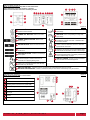
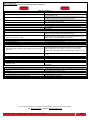
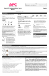
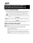
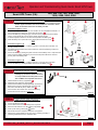
Operation and Troubleshooting Quick Guide: Smart UPS Tower
Smart-UPS Tower (VA):
STEP 1:
420, 620, 700, 750, 1000, 1400,
1500, 2200, 3000, 5000
Connect the UPS’s Internal Batteries (Figure 1):
2
1
NOTE: The Battery Disconnect/Connector may vary or be omitted on some
models. Figure 1 illustrates some of the variations in connectors. Please
follow the illustration which best resembles your UPS.
Procedure for Figure 1: (1, 2, 3)
1.1 Grasp the top edge of the bottom front cover and tilt it out. Use a flat-blade screwdriver or a
coin to remove the two battery door screws and open the door 1
1.2 Connect the battery by pressing the gray connector into the plug at the top of the battery
housing. A snap will be felt as the connector partially engages the jack.
A second snap will be felt as the connector securely seats in the battery jack 2
1.3 Close the battery door, replace the screws, and replace the lower front cover 3
3
OR
Procedure for Figure 1: (A)
1.1 Locate the ‘Battery Disconnect’ or ‘Battery Connector’ on the rear panel of the UPS. It is
typically a Yellow connector.
1.2 If the Battery Disconnect/Connector has a metal cover, remove the fastening screws and
move the cover A
1.3 Connect the battery by pressing the yellow connector into the Battery Jack. A snap will be felt
as the connector partially engages the jack. A second snap will be felt as the connector
securely seats in the Battery Jack.
OR
OR
B
A
Procedure for Figure 1: (B)
1.1 Locate the ‘Battery Disconnect’ or ‘Battery Connector’ on the rear panel of the UPS.
1.2 Connect the battery by pressing the Black connector into the Battery Jack B
STEP 2:
Figure 1
Install UPS accessories (Figure 2):
NOTE: Ensure the UPS is turned off prior to
installing any accessories. Some accessories
are not provided with the UPS, please contact
APC or CBM for the compatible accessories.
2
1
2.1 Install SmartSlot accessory (if applicable) 1
2.2 Install Step-down transformer (if applicable).
2.3 Install all external Battery Packs (if applicable). The External
Battery Pack connector is located on the rear panel of the
UPS, and is either BLUE (48V) or GREY (24V) 2
If the Connector has a metal cover, remove the fastening
screws and move the cover as in Figure 1.A. Figure 2
STEP 3:
Connect wiring & charge UPS (Figure 3):
NOTE: Ensure equipment is turned off.
3.1 Connect equipment to UPS 1
3.2 Connect UPS Power Cord to a suitable power receptacle.
3.3 Set UPS circuit breakers to the ‘ON’ position (if applicable) 3
3.4 Power-up the UPS by pressing the
button.
2
3.5 Wait for the Self-Test to complete, then power-up equipment.
3.6 Allow UPS to charge batteries for 24 hours prior to operating on battery or
performing additional Self-Test or Calibration tests.
1
2
3
Figure 3
c o a s t T e c _ O T Q G _ S U T 1 _ 2 0 1 3 0 1 0 1 V 0 6 Page 1
UPS Front Panel (Figure 4):
NOTE: Symbols & functions may differ on some UPS models.
Figure 4 illustrates some of the variations in displays.
Please use the illustration which best resembles your UPS.
D
A
B
3
7
1
8
C
9
8
F
9
E
7
C
9
3
7
G
4
8
6
5
2
1
2
3
Figure 4
POWER ‘ON’ BUTTON - Button to turn UPS on
A
& perform manual self-test.
POWER ‘OFF’ BUTTON - Button to turn UPS
B
off.
6
input voltage.
AVR TRIM - UPS is compensating for a high utility
input voltage.
OVERLOAD - The power demand from the load has
C exceeded the capacity of the UPS. A sustained alarm
tone is also emitted.
POWER ‘ON/OFF’ BUTTON - Button to turn
UPS on or off.
LOAD CAPACITY - The load is indicated by the
D number of sections illuminated, one to five. Each bar
represents 20% of the load.
4 ESCAPE BUTTON - Button to exit a sub-menu.
5
AVR BOOST- UPS is compensating for a low utility
BATTERY CHARGE - The battery charge level is
E indicated by the number of sections illuminated. When
all five blocks are illuminated, the UPS is at full charge.
ENTER BUTTON - Button to confirm a selection
on the menu.
SYSTEM FAULTS - The system has a fault. The
F fault number will illuminate on the display interface. See
“UPS Troubleshooting” on page 3
UP/DOWN BUTTONS – Buttons to scroll though
menu options.
ONLINE - UPS is supplying utility power to the
7 connected equipment. If not lit, the UPS is not
turned ON, or is supplying battery power.
G
DISPLAY SCREEN – Display important information
about the UPS and connected equipment.
ON BATTERY - UPS is supplying battery backup
8 power to the connected equipment. UPS will beep
four times every 30 seconds.
9
REPLACE BATTERY - UPS fails a self-test, or battery is bad. UPS makes short beeps for a minute.
BATTERY DISCONNECTED - Flashes to indicate the battery is disconnected. UPS will beep every two seconds.
UPS Back Panel (Figure 5):
Figure 5
NOTE: Panel layout may differ on some models.
1
USB port
2
RJ45 connector - serial UPS monitoring port
3
Chassis ground connection screw (TVSS GND)
4
SmartSlot for optional NMC accessory card
5
Circuit breaker/Overload protection
6
UPS input
7
Outlets
8
EPO connector
8
4
2
1
1
3
4
7
5
6
2
c o a s t T e c _ O T Q G _ S U T 1 _ 2 0 1 3 0 1 0 1 V 0 6 3
7
5
6
Page 2
UPS Troubleshooting:
NOTE: Troubleshooting procedures may differ depending on UPS model.
Problem:
Solution:
UPS will not turn on
Press the ON button once to power the UPS and the load.
Check that the power cable from the UPS to the power supply is securely
connected at both ends.
Reduce the load on the UPS by unplugging equipment and reset the circuit
breaker (on back of UPS) by pressing the plunger back in.
Check the AC power supply to the UPS with a table lamp. If the light is very
dim, have the utility voltage checked.
Confirm the battery connections.
• ON button not pushed.
• UPS not connected to AC power supply.
• UPS input circuit breaker tripped.
• Very low or no utility voltage.
• Battery not connected properly.
UPS will not turn off
Do not attempt to use the UPS. Unplug the UPS and have it serviced
immediately.
• Internal UPS fault.
UPS operates on-battery although normal line voltage exists
•
UPS’s input circuit breaker tripped.
•
Very high, low, or distorted line voltage. Inexpensive fuel powered
generators can distort the voltage.
•
Normal UPS operation.
Reduce the load on the UPS by unplugging equipment and reset the circuit
breaker (on back of UPS) by pressing the plunger back in.
Move the UPS to a different outlet on a different circuit. Test the input
voltage with the utility voltage display. If acceptable to the load, reduce the
UPS’s sensitivity. See User’s Manual for procedures.
UPS beeps occasionally
None. The UPS is protecting the load.
UPS does not provide expected backup time
•
The UPS’s battery is weak due to recent outage or is near the end of its
service life.
•
The UPS is overloaded.
•
The UPS has been shut down by remote control.
Charge the battery. Batteries require recharging after extended outages.
Also, they wear faster when put into service often or when operated at
elevated temperatures. If the battery is near the end of its service life,
consider replacing the battery even if the replace battery indicator is not yet
lit.
Check the UPS’s load display. Unplug less needed equipment, such as
printers.
Front panel indicators flash sequentially
None. The UPS will restart automatically when utility power returns.
All indicators are lit and UPS emits a constant beeping
Do not attempt to use the UPS. Turn the UPS off and have it serviced
immediately.
•
Internal UPS fault.
•
The UPS is shut down and the battery is discharged from an extended
outage.
•
•
Weak batteries.
Replacement batteries not connected properly.
All indicators are off and UPS is plugged into wall outlet
None. The UPS will return to normal operation when the power is restored
and the battery has a sufficient charge.
The replace battery light is lit
Do another self-test to see if it clears.
Confirm the battery connections.
For the complete User Manual or comprehensive troubleshooting, please visit the following websites:
APC: http://www.apc.com or coastTec: http://www.coastTec.com
c o a s t T e c _ O T Q G _ S U T 1 _ 2 0 1 3 0 1 0 1 V 0 6 Page 3