1
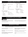
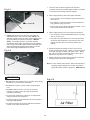
®
User Manual
Read and understand this manual before using machine.
DELUXE AIR FILTER – 3 SPEED
Model Number
65120
®
C
US
STEEL CITY TOOL WORKS
VER. 09.2014
Manual Part No. OR74185N
®
THANK YOU fo r pu rch as ing yo ur ne w St ee
l Ci ty
sig ne d, tes ted , an d
de
en
be
s
ha
ter
fil
air
is
Th
r.
lte
Fi
Ai r
mi nd . W he n pr op erl y
in
r,
me
sto
cu
the
u,
yo
th
wi
d
cte
ins pe
wi ll pr ov ide yo u wi th
us ed an d ma int ain ed , yo ur air fil ter
is wh y it is ba ck ed by
ye ars of tro ub le fre e se rv ice , wh ich
nti es in the bu sin es s.
on e of the lon ge st ma ch ine ry wa rra
pr od uc ts in the St ee l
Th is air fil ter is jus t on e of ma ny
ch ine ry an d is pr oo f of
Ci ty' s fam ily of wo od wo rk ing ma
r sa tis fac tio n.
ou r co mm itm en t to tot al cu sto me
r ex ce lle nc e ea ch an d
fo
ive
str
to
e
nu
nti
co
we
ty
Ci
l
ee
At St
u, ou r cu sto me r. Fo r
yo
of
on
ini
op
the
lue
va
d
an
y
da
ev ery
St ee l Ci ty To ol Wor ks ,
co mm en ts ab ou t yo ur air fil ter or
ee lc it yt oo lw or ks .c om
ple as e vis it ou r we b sit e at ww w. st
2
TABLE OF CONTENTS
INTRODUCTION
SECTION 1
Warranty .................................................................................................................................................4
SECTION 2
Product Specifications ............................................................................................................................7
SECTION 3
Accessories and Attachments ................................................................................................................7
SECTION 4
Definition of Terms ..................................................................................................................................7
SECTION 5
Feature Identification ..............................................................................................................................8
SECTION 6
General Safety........................................................................................................................................9
SECTION 7
Product Safety ......................................................................................................................................11
SECTION 8
Electrical Requirements........................................................................................................................12
SECTION 9
Unpacking & Inventory..........................................................................................................................14
SECTION 10
Assembly ..............................................................................................................................................15
SECTION 11
Operations ............................................................................................................................................17
SECTION 12
Maintenance .........................................................................................................................................18
SECTION 13
Troubleshooting ....................................................................................................................................19
SECTION 14
Parts List..........................................................................................................................................20-21
INTRODUCTION
This user manual is intended for use by anyone working with this machine. It should be kept available
for immediate reference so that all operations can be performed with maximum efficiency and safety.
Do not attempt to perform maintenance or operate this machine until you have read and understand the
information contained in this manual.
This Air Filter is intended to filter dry airborne wood dust only. It must be limited to non-explosive,
non-metallic atmosphere. This machine is not to be modified for any reasons.
The drawings, illustrations, photographs, and specifications in this user manual represent your machine
at time of print. However, changes may be made to your machine or this manual at any time with no
obligation to Steel City Tool Works.
3
WARRANTY
2 YEAR LIMITED WARRANTY
Steel City Tool Works, LLC (SCTW) warrants this SCTW machinery to be free of defects in workmanship and materials for a period
of 2 years from the date of the original retail purchase by the original owner for domestic use. Granite components are warranted for
2 years based on normal use and is void if non SCTW accessories are used that cause the break or chip. Customer must advise
SCTW within 30 days for any damage or defect found upon receipt of the product to qualify for the warranty on granite.
The warranty does not cover any product used for professional or commercial production purpose nor for industrial or educational
applications. Such cases are covered by our 1 year Limited Warranty with the Conditions and Exceptions listed below.
Conditions and exception:
Warranty applies to the original buyer only and may not be transferred. Original proof of purchase is required.
Warranty does not include failures, breakage or defects deemed after inspection by an Authorized Service Center, (ASC) or agent of,
have been directly or indirectly caused by or resulting from improper use, lack of or improper maintenance, misuse or abuse,
negligence, accidents, damage in handling or transport, or normal wear and tear of any part or component.
Additionally, warranty is void if repairs or alterations are made to the machine by an unauthorized service center without the direct
consent of SCTW
Consumables such as blades, knives, bits and sandpaper are not covered.
Wear items such as drive belt, bearings, switch, are covered for 1 year.
To file a claim of warranty or to find a service center, call toll free 877-724-8665 or email [email protected] and
you must be able to present the original or photo copy of the sales receipt including the serial number from the machine and/or carton.
SCTW will inspect, repair or replace, at its expense and its option, any part that has proven to be defective in workmanship or
material, provided that the customer returns the product prepaid to a designated ASC and provides SCTW with a reasonable
opportunity to verify the alleged defect by inspection. SCTW will return the product or replacement at our expense unless it is
determined by us that there is no defect or that the defect resulted from causes not within the scope of our warranty in which case we
will, at your direction, dispose of or return the product. In the event you choose to have the product returned, you will be responsible
for the handling and shipping costs of the return.
SCTW furnishes the above warranties in lieu of all other warranties, express or implied. SCTW shall not be liable for any special,
indirect, incidental, punitive or consequential damages, including without limitation loss of profits arising from or related to the
warranty, the breach of any agreement or warranty, or the operation or use of its machinery, including without limitation damages
arising from damage to fixtures, tools, equipment, parts or materials, direct or indirect loss caused by and other part, loss of revenue
or profits, financing or interest charges, and claims by and third person, whether or not notice of such possible damages has been
given to SCTW. Damages or any kind for any delay by or failure of SCTW to perform its obligations under this agreement or claims
made a subject of a legal proceeding against SCTW more than one (1) year after such cause of action first arose.
The validity, construction and performance of this Warranty and any sale of machinery by SCTW shall be governed by the law of the
Commonwealth of Pennsylvania, without regard to conflicts of law’s provisions of any jurisdiction. Any action related in any way to
any alleged or actual offer, acceptance or sale by SCTW or any claim related to the performance of and agreement including without
limitation this Warranty, shall take place in the federal or state courts in Allegheny County, Pennsylvania.
Warranty registration card must be submitted to SCTW for purpose of proof within 90 days of purchase with a copy of the sales
receipt. Failure to do so will, revert the 2 year warranty to 1 year as in the terms stated above. This registration is also needed to
facilitate contact in case of a safety recall.
This warranty gives you specific legal rights and you may have other rights which vary in certain States or Provinces.
Note to user
This instruction manual is meant to serve as a guide only. Specification and references are subject to change without prior notice.
Check the website www.steelcitytoolworks.com for updated manuals with reference to the VER# located on the front page.
LIMITED WARRANTY – ACCU-SHOP line of bench top tools
Steel City Tool Works, LLC (SCTW) warrants this SCTW ACCU-SHOP machinery to be free of defects in workmanship and materials
for a period of 2 years from the date of the original retail purchase by the original owner for domestic use.
Consumables such as blades, knives, bits and sandpaper are not covered.
Wear items such as drive belt, bearings, switch, are covered for 1 year.
The warranty does not cover any product used for professional or commercial production purpose nor for industrial or educational
applications. Such cases are covered by our 30 days Limited Warranty with the Conditions and Exceptions listed previously.
4
WARRANTY CARD
Name ________________________________________________
Street _______________________________________________
Apt. No. ______________________________________________
City _________________________ State ______ Zip __________
Phone Number_________________________________________
E-Mail ________________________________________________
The following information is given on a voluntary basis
and is strictly confidential.
Where did you purchase your STEEL CITY machine?
Store: ____________________________________________
City:______________________________________________
2.
How did you first learn of Steel City Tool Works?
___ Advertisement
___ Mail Order Catalog
___ Web Site
___ Friend
___ Local Store
Other_______________________
! CUT HERE
3.
4.
5.
6.
7.
Which of the following magazines
___ American Woodworker
––– Cabinetmaker
___ Fine Homebuilding
___ Journal of Light Construction
___ Popular Mechanics
___ Popular Woodworking
___ WOOD
___ WOODEN Boat
___ Woodsmith
___ Woodworker
___ Workbench
What is your age group?
___ 20 to 29 years
___ 40 to 49 years
___ 60 to 69 years
9.
How many Steel City machines do you own? _____________
11. Which benchtop tools do you own? Check all that apply.
___ Belt Sander
___ Belt / Disc Sander
___ Drill Press
___ Band Saw
___ Grinder
___ Mini Jointer
___ Mini Lathe
___ Scroll Saw
___ Spindle / Belt Sander
Other______________________
do you subscribe to?
___ American How-To
___ Family Handyman
___ Fine Woodworking
___ Old House Journal
___ Popular Science
___ Today’s Homeowner
___ Woodcraft
___ Woodshop News
___ Woodwork
___ Woodworker’s Journal
Other_________________
12. Which portable / hand held power tools do you own?
Check all that apply.
___ Belt Sander
___ Biscuit Jointer
___ Dust Collector
___ Circular Saw
___ Detail Sander
___ Drill / Driver
___ Miter Saw
___ Orbital Sander
___ Palm Sander
___ Portable Thickness Planer
___ Saber Saw
___ Reciprocating Saw
___ Router
Other_______________________
13. What machines / accessories would you like to see added to the
STEEL CITY line?
____________________________________________________
____________________________________________________
Which of the following woodworking / remodeling shows do
you watch?
___ Backyard America ___ The American Woodworker
___ Home Time
___ The New Yankee Workshop
___ This Old House
___ Woodwright’s Shop
Other__________________________________________
What is your annual household
___ $20,000 to $29,999
___ $40,000 to $49,999
___ $60,000 to $69,999
___ $80,000 to $89,999
How would you rank your woodworking skills?
___ Simple
___ Intermediate
___ Advance
___ Master Craftsman
10. What stationary woodworking tools do you own?
Check all that apply.
___ Air Compressor
___ Band Saw
___ Drill Press
___ Drum Sander
___ Dust Collection
___ Horizontal Boring Machine
___ Jointer
___ Lathe
___ Mortiser
___ Panel Saw
___ Planer
___ Power Feeder
___ Radial Arm Saw
___ Shaper
___ Spindle Sander
___ Table Saw
___ Vacuum Veneer Press
___ Wide Belt Sander
Other____________________________________________
Product Description:_____________________________________
Model No.: ___________________________________________
Serial No. _____________________________________________
1.
8.
14. What new accessories would you like to see added?
____________________________________________________
____________________________________________________
income?
___ $30,000 to $39,999
___ $50,000 to $59,999
___ 70,000 to $79,999
___ $90,000 +
15. Do you think your purchase represents good value?
___Yes
___ No
16. Would you recommend STEEL CITY products to a friend?
___ Yes
___ No
___ 30 to 39 years
___ 50 to 59 years
___ 70 + years
17. Comments:
____________________________________________________
____________________________________________________
____________________________________________________
____________________________________________________
____________________________________________________
How long have you been a woodworker?
___ 0 to 2 years
___ 2 to 8 years
___ 8 to 20 years
___ over 20 years
5
FOLD ON DOTTED LINE
PLACE
STAMP
HER E
SteelCityToolWorks
#4 Northpoint Court
Bolingbrook, IL 60440
FOLD ON DOTTED LINE
6
PRODUCT SPECIFICATIONS
Product Dimensions :
Motor Specifications:
Type
Industrial, ball bearing
Footprint
28 ” x 24 ” (71cm x 61cm)
Continuous Duty
1/5
Length
28 ” (71cm)
Horsepower
Width
24 ” (61cm)
Amps
2.0 / 2.6 / 6.0
Height
12 ” (30.5cm)
Voltage
120
Weight
59Lbs.(27Kg)
Phase
single
Hertz
60
RPM
850 / 1050 / 1200 (no load)
Shipping Dimensions :
Product Specifications :
Noise Lever (Decibel)
68dB
CFM
540 / 730 / 1250
Outer Filter
5-micron, electristatic
Inner Filter
1 micron
Filter Cycle
(20’ x 20’ x 8’)
10 / 14 / 22 times per hour
Carton Type
Cardboard
Length
30-3/8 ” (77cm)
Width
26 ” (66cm)
Height
14.2 ” (36cm)
Gross Weight
73Lbs. (33Kg)
ACCESSORIES AND ATTACHMENTS
! WARNING
Use only accessories recommended for this machine.
Contact your local Steel City dealer for accessories, or
Using other accessories may cause serious injury and
visit our website at : www.steelcitytoolworks.com.
cause damage to the machine.
DEFINITION OF TERMS
Below are some terms that will help you to understand and setup your Air Filter
and design your own Air Filter System.
C.F.M.=Cubic Feet/Minute - A measurement of the
amount of air volume that can move through a dust
collector in one minute.
Air Filter or Ambient Air Filter - A machine used to
filter dry airborne wood dust.
Dust Collector - A machine used to collect fine wood
dust and chips.
Static Pressure - A measurement of the amount of the
resistance to airflow in a dust collection sstem.
Dust Collection System - A dust collector connected
to multiple woodworking machine utilizing various
types of hose/pipe and fittings.
One Micron - One micron is equal to one millionth of a
meter.
7
FEATURE IDENTIFICATION
Fig. 1-1
F
C
A
B
D
E
A. Air Filter
B. Handle
C. Eye-bolt
D. Outer Electrostatic Pre-Filter
E. Intake Side
F.
Exhaust Side
8
GENERAL SAFETY
!
WARNING
!
WARNING
TO AVOID serious injury and damage to the machine,
read and follow all Safety and Operating Instructions
before assembling and operating this machine.
This manual is not totally comprehensive. It does not
and can not convey every possible safety and operational problem which may arise while using this
machine. The manual will cover many of the basic and
specific safety procedures needed in an industrial environment.
Exposure to the dust created by power sanding, sawing, grinding, drilling and other construction activities
may cause serious and permanent respiratory or
other injury, including silicosis (a serious lung disease), cancer, and death. Avoid breathing the dust,
and avoid prolonged contact with dust. The dust
may contain chemicals known to the State of
California to cause cancer, birth defects or other
reproductive harm.
All federal and state laws and any regulations having
jurisdiction covering the safety requirements for use of
this machine take precedence over the statements in
this manual. Users of this machine must adhere to all
such regulations.
Some examples of these chemicals are:
• Lead from lead-based paints.
• Crystalline silica from bricks, cement and other
masonry products.
• Arsenic and chromium from chemically-treated
lumber.
Below is a list of symbols that are used to attract your
attention to possible dangerous conditions.
!
This is the international safety alert symbol. It is used
to alert you to potential personal injury hazards. Obey
all safety messages that follow this symbol to avoid
possible injury or death.
!
Always operate tool in well ventilated area and provide for proper dust removal. Use a dust collection
system along with an air filtration system whenever
possible. Always use properly fitting NIOSH/OSHA
approved respiratory protection appropriate for the
dust exposure, and wash exposed areas with soap
and water.
DANGER
Indicates an imminently hazardous situation which, if
not avoided, WILL result in death or serious injury.
!
1. To avoid serious injury and damage to the machine,
read the entire User Manual before assembly and
operation of this machine.
WARNING
Indicates a potentially hazardous situation which, if not
avoided, COULD result in death or serious injury.
!
CAUTION
!
WARNING
Indicates a potentially hazardous situation, if not avoided, MAY result in minor or moderate injury. It may also
be used to alert against unsafe practices.
CAUTION
2. ALWAYS wear eye protection. Any machine can
throw debris into the eyes during operations,
which could cause severe and permanent eye
damage. Everyday eyeglasses are NOT safety
glasses. ALWAYS wear Safety Goggles (that
comply with ANSI standard Z87.1) when operating power tools.
CAUTION used without the safety alert symbol indicates a potentially hazardous situation which, if not
avoided, may result in property damage.
NOTICE
This symbol is used to alert the user to useful information about proper operation of the machine.
9
!
10. SECURELY anchor this unit into a supporting structure when suspending it from the ceiling. Always
keep a minimum of 7 feet between the bottom of
the unit and the floor surface to allow for sufficient
head clearance. Use only a chain rated for a minimum of 150 lb. working load to adequately hold the
unit. Use steel S-hooks that are at least 1/4” in
diameter to suspend the unit from the ceiling. Lagtype bolts used to suspend the unit from the ceiling
must be threaded at least 1-1/2” into the supporting
structural members.
WARNING
3. ALWAYS wear hearing protection. Plain cotton is
not an acceptable protective device. Hearing
equipment should comply with ANSI S3.19
Standards.
!
11. SUPPORT this unit or securely clamp it to the work
surface when it is used in a portable application to
eliminate potential movement and/or damage from
falling.
WARNING
12. DO NOT operate this unit without the filters in
place.
4. ALWAYS wear a NIOSH/OSHA approved dust
mask to prevent inhaling dangerous dust or airborne particles.
13. MAKE CERTAIN that the intake and exhaust areas
are clean prior to starting the unit. A clogged intake
or exhaust can cause a fire and/or explosion.
5. ALWAYS keep the work area clean, well lit, and
organized. DO NOT work in an area that has slippery floor surfaces from debris, grease, and wax.
!
6. ALWAYS unplug the machine from the electrical
receptacle before making adjustments, changing
parts or performing any maintenance.
WARNING
14. KEEP all fingers, arms, and hands away from
the fan. Avoid all exposure to rotating parts to
prevent injury.
7. DO NOT leave the air filter plugged into the
electrical outlet. Unplug air filter from the outlet
when not in use and before servicing, changing
filters, unclogging and cleaning.
!
8. DO NOT use this unit to filter metal dust. Combining wood and metal dust can create an explosion or
fire hazard. This air filter is intended for use
where only dry airborne dust is present. Its use
should be limited to non-explosive, non-metallic
atmospheres.
WARNING
15. DO NOT handle the plug or air filter with wet
hands.
9. DO NOT use this machine to dissipate fumes or
smoke; fire or explosions can result.
16. DO NOT pull the air filter by the power cord.
NEVER allow the power cord to come in contact
with sharp edges, hot surfaces, oil or grease.
10
PRODUCT SAFETY
1. Serious personal injury may occur if normal safety
precautions are overlooked or ignored. Accidents
are frequently caused by lack of familiarity or failure
to pay attention. Obtain advice from supervisor,
instructor, or another qualified individual who is
familiar with this machine and its operations.
!
9. DO NOT handle the plug or air filter with
wet hands.
2. Every work area is different. Always consider safety first, as it applies to your work area. Use this
machine with respect and caution. Failure to do so
could result in serious personal injury and damage
to the machine.
10. NEVER use the air filter near any flammable or
combustible liquids.
3. Prevent electrical shock. Follow all electrical and
safety codes, including the National Electrical Code
(NEC) and the Occupational Safety and Health
Regulations (OSHA). All electrical connections and
wiring should be made by qualified personnel only.
!
WARNING
11. NEVER use the air filter to dissipate fumes or
smoke. NEVER pick up anything that is burning or
smoking, such as cigarettes, matches or hot ashes.
12. USE only as described in this manual. USE accessories only recommended by Steel City.
WARNING
13. DO NOT pull the air filter by the power cord.
NEVER allow the power cord to come in contact
with sharp edges, hot surfaces, oil or grease.
14. REPLACE a damaged cord immediately. DO NOT
use a damaged cord or plug. If the air filter is not
operating properly, or has been damaged, left outdoors or has been in contact with water.
4. TO REDUCE the risk of electrical shock. DO
NOT use this machine outdoors. DO NOT
expose to rain. Store indoors in a dry area.
15. DO NOT use the air filter as a toy. DO NOT use
near or around children.
5. STOP using this machine, if at any time you experience difficulties in performing any operation.
Contact your supervisor, instructor or machine service center immediately.
!
6. Safety decals are on this machine to warn and
direct you to how to protector yourself or visitors
from personal injury. These decals MUST be maintained so that they are legible. REPLACE decals
that are not legible.
WARNING
16. DO NOT insert fingers or foreign objects into
the dust intake port. Keep hair, loose clothing,
fingers, and all body parts away from openings
and moving parts of the air filter.
7. DO NOT leave the air filter plugged into the
electrical outlet. Unplug air filter from the outlet
when not in use and before servicing, changing
bags, unclogging and cleaning.
17. PERIODICALLY INSPECT filter for any cuts, rips
or tears. NEVER operate the air filter with a
damaged filter.
8. ALWAYS turn the power switch “OFF” before
unplugging the air filter.
18. The air filter is designed for home use or light
commercial duty ONLY.
19. CONNECT air filter to a properly grounded outlet
only. See grounding instructions.
11
ELECTRICAL REQUIREMENTS
!
TO REDUCE the risk of electrical shock, DO NOT use
machine outdoors. DO NOT expose to rain. Store
indoors in a dry area.
WARNING
TO PREVENT electrical shock, follow all electrical and
safety codes, including the National Electrical Code
(NEC) and the Occupational Safety and Health
Regulations (OSHA). All electrical connections and
wiring should be made by qualified personnel only.
DO NOT connect the machine to the power source
before you have completed the set up process. DO
NOT connect the machine to the power source until
instructed to do so.
GROUNDING INSTRUCTIONS
!
PLUGS/RECEPTACLES
WARNING
!
WARNING
This machine MUST BE GROUNDED while in use to
protect the operator from electric shock.
• Electrocution or fire could result if this machine is
not grounded properly or if the electrical configuration does not comply with local and state electrical
codes.
In the event of a malfunction or breakdown, GROUNDING provides the path of least resistance for electric
current and reduces the risk of electric shock. This
machine is equipped with an electric cord that has an
equipment-grounding conductor and a grounding plug.
The plug MUST be plugged into a matching electrical
receptacle that is properly installed and grounded in
accordance with ALL local codes and ordinances.
• MAKE CERTAIN the machine is disconnected
from power source before starting any electrical|
work.
• MAKE SURE the circuit breaker does not exceed
the rating of the plug and receptacle.
If a plug is provided with your machine DO NOT modify
the plug. If it will not fit your electrical receptacle, have
a qualified electrician install the proper connections to
meet all electrical codes local and state. All connections
must also adhere to all of OSHA mandates.
The motor supplied with your machine is a 120 volt,
alternating current, 60 hertz, single phase motor. It is
shipped wired for 120 volt application. Never connect
the green or ground wire to a live terminal.
IMPROPER ELECTRICAL CONNECTION of the equipment-grounding conductor can result in risk of electric
shock. The conductor with the green insulation (with or
without yellow stripes) is the equipment-grounding
conductor. DO NOT connect the equipment-grounding
conductor to a live terminal.
This tool is intended for use on a circuit that has an
electrical receptacle as shown in Figure 1-1. Figure 1-1
shows a NEMA approved 3-wire, 15 amp electrical plug
and receptacle that have a grounding conductor. If a
properly grounded electrical receptacle is not available,
an adapter as shown in Figure 1-2 can be used to temporarily connect this plug to a 2-contact ungrounded
receptacle. The adapter has a rigid lug extending from it
that MUST be connected to a permanent earth ground,
such as a properly grounded receptacle box. THIS
ADAPTER IS PROHIBITED IN CANADA.
Check with a qualified electrician or service personnel if
you do not completely understand the grounding
instructions, or if you are not sure the tool is properly
grounded.
12
EXTENSION CORDS
Fig. 1-1
!
WARNING
To reduce the risk of fire or electrical shock, use the
proper gauge of extension cord. When using an
extension cord, be sure to use one heavy enough to
carry the current your machine will draw.
The smaller the gauge-number, the larger the diameter
of the extension cord is. If in doubt of the proper size of
an extension cord, use a shorter and thicker cord. An
undersized cord will cause a drop in line voltage resulting in a loss of power and overheating.
Fig. 1-2
!
CAUTION
USE ONLY a 3-wire extension cord that has a 3-prong
grounding plug and a 3-pole receptacle that accepts the
machine’s plug.
If you are using an extension cord outdoors, be sure it
is marked with the suffix “W-A” (“W” in Canada) to indicate that it is acceptable for outdoor use.
Make certain the extension cord is properly sized, and
in good electrical condition. Always replace a worn or
damaged extension cord immediately or have it
repaired by a qualified person before using it.
Protect your extension cords from sharp objects, excessive heat, and damp or wet areas.
MINIMUM RECOMMENDED GAUGE FOR EXTENSION CORDS (AWG)
120 VOLT OPERATION ONLY
13
25’ LONG
50’ LONG
100’ LONG
0 to 6 Amps
18 AWG
16 AWG
16 AWG
6 to 10 Amps
18 AWG
16 AWG
16 AWG
10 to 12 Amps
16 AWG
16 AWG
14 AWG
UNPACKING & INVENTORY
This Air Filter will require a minimal amount of
assembly.
Filter should only be turned “ON” after all the parts
have been obtained and installed correctly. For missing
parts, contact Steel City at 1-877-SC4-TOOL.
Remove all of the parts from the shipping box and lay
them on a clean work surface. Compare the items to
figures 1-2 and 1-3, verify that all items are accounted
for before discarding the shipping box.
!
CAUTION: Make certain shipping blocks have been
removed from between cabinet and blower assembly,
before unit is turned on. You will have to remove the
filters to remove the shipping blocks.
WARNING
The following items are to be provided in the shipping
box:
If any parts are missing, do not attempt to plug in the
power cord and turn “ON” the Air Filter. The Air
Fig. 1-1
A. Air Filter
Fig. 1-2
B. Eye-bolt 5/16-18 x 1-1/2” (4)
Fig. 1-3
C. Flange nut 5/16-18 (4)
E. Remote Control Unit
(Batteries not included)
D. Rubber Pad (4)
C
E
D
B
14
INSTRUCTION FOR REMOVING SHIPPING BLOCKS
1.Remove the Electrostatic per filter P/N54 and the
three pocket inner filter P/N 53.
Fig.1-5
2.Using a screw driver, remove the two screws on
either side of the inlet guard screen. SEE FIG. 1-4
Fig.1-4
4.Replace inlet guard screen and install and tighten
the two screws removed in step#2.
5.Replace the three pocket inner bag filter and the
electrostatic per filter. Plug unit in and turn on.
3.Pull inlet guard screen to one side and remove
shipping blocks from top and bottom of housing.
SEE FIG. 1-5
ASSEMBLY
!
WARNING
CAUTION: For operator safety, we sugest that the
unit be clamped down when used on a workbench or
positioned on sawhorses.
1. DO NOT assemble the Air Filter until you are sure
the tool IS NOT plugged in.
2. DO NOT assemble the Air Filter until you are sure
the power switch is in the "OFF" position.
2. There are two lifting handles located on each side of
the air filter. These handles should be used to carry
the Air Filter from place to place. To avoid damage to
the air filters, carry the air filter with the filters
positioned away from your body.
3. For your own safety, DO NOT connect the machine
to the power source until the machine is completely
assembled and you read and understand the entire
Owner's Manual.
CAUTION: This Air Filter weighs approximately 55
pounds.
The Air Filter can be used as a portable or stationary
unit. As a portable unit it can be moved and placed
near the work to be done. As a stationary unit it can
be hung overhead in the shop. Determine which type
of use is best fitted for your applications and proceed
to that section in the assembly instructions.
STATIONARY UNIT ASSEMBLY
THIS TOOL WEIGHS APPROXIMATELY 55 POUNDS.
MAKE CERTAIN THE UNIT IS SECURELY SUPPORTED WHEN MOUNTING TO A CEILING OR OVERHEAD
SUPPORT.
PORTABLE UNIT ASSEMBLY
!
WARNING
1. Remove four screws from the top of Air Filter (B);
one of the screws is shown at (A). SEE FIG 2-1.
MAKE CERTAIN THE AIR FILTER DISCONNECTED
FROM THE POWER SOURCE.
2. Thread each of the provided No. 5/16-18 flange nut
approximately half way onto the provided No. 5/16-18
x 2" eye-bolts.
1. Place the Air Filter on its side. Locate the selfadhesive rubber pads supplied with the unit. Carefully place one rubber pad on each bottom corner
of the Air Filter. The rubber pads will help eliminate
vibration and noise.
3. Thread each eye-bolt/flange nut assembly into the
holes where the screws were removed in STEP 1.
15
1. The Air Filter must be supported by wood or
concrete structural member able to hold a minimum
of 150 pounds working load per support.
Fig.2-1
2. When Supported by Wood structural member:
B
• The minimum recommended Lag eye-bolt size is
5/16-18 x 2".
• Pre-drilled 1/4" pilot holes are recommended to
help guide the lag eye-bolts.
A
• Ensure the lag eye-bolts penetrate at least 1-1/2"
into the wood structural member.
3. When supported by Concrete structural member:
4. Figure 2-2 shows one of the four eye-bolts (E)
assembled to the top of the Air Filter. NOTE : To
adjust the height of the Air Filter, loosen flange nuts
(F) and rotate eye-bolts as necessary. IMPORTANT : For safety reasons, eye-bolts must be
threaded at least eight complete turns into tapped
hole in top of Air Filter. Make certain the flange nuts
are tightened down against the surface of the Air
Filter after height adjustments are made.
• The minimum recommended Expansion eye-bolt
size is 5/16-18 x 2".
• Pre-drill 5/16" pilot holes into concrete structure
and press the Expansion eye-bolt into hole and
tighten the bolt until it is securely held to the
ceiling.
4. Measure the desire length of chain and cut four
chains of the same length. Attach a connecting link
of similar strength to each end of the chain. Hang
the chains with the connecting links to the Lag or
Expansion eye-bolts in the ceiling.
Fig.2-2
E
5. Raise and secure the Air Filter eye-bolts to the four
hanging chains with connecting links.
Note: For the safety requirement, We recommend the
hanging angle between the chains and ceiling
perpendicularity within 5 degrees. SEE FIG 2-3.
F
!
WARNING
Fig. 2-3
• Do not fasten onto sheet rock or dry wall, drop ceiling
tile/frame or non structural members.
• Do not use a rope or power cord to suspend the
unit.
• Do not locate the unit in a corner or near any
heating or cooling vents to keep the Air Filter
operating efficiently.
• Do use chain rated for a minimum of 150 pounds
working load for each support.
• Do keep hanging angle between the chain and the
ceiling perpendicular.
• Do keep minimum seven feet clearance between
bottom of Air Filter and the floor.
16
OPERATIONS
Fig.3
CAUTION: Make certain shipping blocks have been
removed from between cabinet and blower assembly,
before unit is turned on.
FUNCTION
This Air Filter is furnished with two filters: an outer prefilter which filters particles that are five microns and
larger, and a secondary disposable three-pocket inner
filter that captures 91% of the dust particles that are
one micron and larger (one micron = one millionth of a
meter). The Air Filter will filter the air in a room
measuring 20" x 20" x 8" up to twenty-two times an
hour. If desired, multiple units can be used to filter
larger areas.
CONNECTING TOOL TO POWER
SOURCE
A separate electrical circuit should be used for your
tools. This circuit should not be less than #14 A.W.G.
wire and should be protected with a 15-amp time lag
fuse. Have a qualified electrician repair or replace
damaged or worn cord immediately. Before connecting
the motor to the power line, make certain the switch is
in the "OFF" position and be sure that the electric
1. To activate the blower unit, first turn on the
current is of the same characteristics as stamped on
the motor nameplate. All line connections should
ON/OFF Switch on the power cord.
16
make good contact. Running on low voltage will
2. Press the "ON/OFF" button (C) on the remote.
damage the motor.
The air filter will begin in the default speed of
Low or "L" on the sensor panel.
ON/OFF SWITCH
3. Press the SPEED button (D) once, and the air
filter will run at the medium or "M" level.
The Air Filter is supplied with an in-line rocker switch
located on the power cord. To START or STOP the
unit, press downward on the rocker switch.
4. Press the SPEED button again, and the air filter
will run at the high or "H" level.
NOTE: The ON/OFF Switch must be turned ON before
using the remote control feature.
5. Press the SPEED button a third time and the air
filter will return to the low or "L" level.
REMOTE CONTROL UNIT
!
6. To turn the machine off, press the "ON/OFF"
button on the remote.
WARNING
This air filter has a timer that can be set by remote
control.
To reduce the risk of fire or electric shock, do not use
this unit with any solid-state speed control device.
The remote control unit (A) provided with this unit is
not considered a solid-state device.
1. When the "TIME" button (B) on the remote
control is pressed, the blower will run for 1/2
hour. An LED light will show up on the sensor
panel.
NOTE: The remote control unit requires two (2) AAA
batteries (not included). The battery housing is
located underneath the back cover of the remote.
2. Pressing the "TIME" button again will set the
blower to run for one hour. Notice that the light
on the sensor panel has now moved to the one
hour location.
Notice that the remote control has three control
buttons: TIME (B), ON/OFF (C), and SPEED (D).
These buttons correspond to the LED sensor panel on
the rear of the machine.
3. When the "TIME" button is pressed a third time,
the blower will run for two hours. At this point,
the green light will show up under the two hour
location.
17
4. When you press the "TIME" button the fourth time,
the blower will run for four hours. Notice that the
indicator light glows at the four hour location.
!
DO NOT USE THIS UNIT TO FILTER METAL DUST.
Combining wood and metal dust can create an explosion or fire hazard. This Air Filter is intended for use
where only dry airborne dust is present. Its use should
be limited to non-explosive, non-metallic atmospheres.
5. All of these functions can be manually controlled by
using the two buttons on the sensor panel.
!
!
WARNING
WARNING
NEVER SECURE MOUNTING HARDWARE TO
DRYWALL, DROP CEILING TILE/FRAME OR NONSTRUCTURAL MEMBERS.
WARNING
DO NOT operate this unit without the filters in place.
NOTE: The Air Filter may produce a slight odor for
the first couple hours of operation due to the
protective coating which is applied to internal
components. This odor will dissipate and should be
disregarded.
!
WARNING
KEEP A MINIMUM OF SEVEN FEET BETWEEN
BOTTOM OF AIR FILTER AND THE FLOOR.
MAINTENANCE
CHANGING AND CLEANING FILTERS
!
3. To replace the inner filter, lift and pull out on the
bottom of the filter.
WARNING
4. Install the new inner filter by placing the top of the
filter in first and allowing the bottom to sit on the air
filter.
• ALWAYS wear eye protection. Any machine can
throw debris into the eyes during operations,
which could cause severe and permanent eye
damage. Everyday eyeglasses are NOT safety
glasses.
• ALWAYS use properly fitting NIOSH/OSHA
approved respiratory protection appropriate for
the dust exposure, and wash exposed areas with
soap and water.
NOTE: Make certain if there is an AIRFLOW ARROW
on either filter, that the arrow points inward toward the
blower of the air filter.
5. Replace the outer pre-filter, by placing the top of the
filter in first and allowing the bottom to sit on the air
filter. Make sure it is sitting inside of the bottom lip
of the air filter.
1. Turn the air filter OFF and let the blower come to a
complete stop before proceeding.
!
LUBRICATION
WARNING
The Air Filter has sealed lubricated bearings in the
motor housing that do not require any additional
lubrication from the operator.
Compressed air can be dangerous. For operator
safety, DO NOT EXCEED an air pressure of 30 PSI or
point air nozzle toward anyone or aim nozzle at your
own body.
CAUTION: DO NOT USE FLAMMABLE MATERIALS
to clean Air Filter.
2. Lift up and pull out on the bottom of the outer prefilter. The outer pre-filter can be cleaned in one of
three methods. Method one is using a shop vacuum
to remove the dust. Method two is by using compressed air to blow the dust out of the filter. Method
three is by washing with soap and water.
!
WARNING
Repairs to the Air Filter should be performed by trained
personnel only. Contact your nearest Steel City
Authorized Service Center for authorized service.
Unauthorized repairs or replacement with non-factory
parts could cause serious injury to the operator and
damage to the Air Filter.
NOTE: The three-pocket inner filter cannot be cleaned
and must be replaced when worn.
18
TROUBLESHOOTING GUIDE
TO PREVENT INJURY TO YOURSELF or damage to the Air Filter, turn the switch to the “OFF” position and
unplug the power cord from the electrical receptacle before making any adjustments.
PROBLEM
Motor does
not start
Motor stalls
(resulting in
blown fuses or
tripped circuit
breakers)
Motor starts
slowly or falls
to come to full
speed
Motor running
too lot
Frequent blowing
of fuse or circuit
breakers
SOLUTION
LIKELY CAUSE(S)
1.Switch not pressed in far enough
or switch in the “OFF”positon.
2.Defective switch
3.Low line voltage
4.Defective motor
5.Power cord switch not turned ON .
1.Depress switch in or make sure switch
is in the “On”position
2.Have switch replaced
3.Correct low line voltage condition.
4.Have motor replace/repaired
5.Turn switch to ON position
NOTE:2,3 and 4 must be done by a qualified
service technician.
1.Circuit overload
2.Low line voltage
3.Incorrect fuses on circuit breakers
4.Short circuit in motor; loose
connections or worn insulation on
lead wires
1.Reduce circuit load
2.Correct low line voltage condition
3.Have correct fuses on circuit breakers
installed
4.Inspec terminals in motor for damaged
insulation and shorted wires and have
them replaced.
1.Defective motor windings.
1.Have motor replaced/repaired
1.Restricted air circulation due
to dust accumulation
1A. Clean dust and restore normal air
circulation.
1B.Clean filters.
1.Fuse or circuit breakers do not
have sufficient capacity
2.Circuit overloaded.
1.Have correct fuses or circuit breakers
installed.
2.Reduce circuit load(turn off other
appliances)
19
PARTS
20
PARTS LIST
KEY
NO.
1
2
3
4
5
6
7
8
11
14
15
16
17
18
19
20
21
22
23
24
25
26
27
28
29
30
PART NO.
OR70284
OR70272
OR91323
SC80401
OR90053
OR70273
SC10001
SC10002
OR70275
SC71001
SC72001
OR90601
SC80402
OR91324
OR90502
OR70274
OR91326
SC76001
OR91345
OR91327
OR91333
SC80101
OR91328
OR91329
OR90601
OR91346
DESCRIPTION
POWER/SWITCH CORD
CONTROL PANEL LABEL
BUSHING
#10-24 x 5/8" PAN HD SCREW
#10 EXT TOOTH WASHER
CONTROL PANEL BOX
BRASS NUT
CIRCUITRY PLANK
CAPACITOR
WIRE NUT CE-2
PROTECTOR, 4AMP
INTAKE WARNING LABEL
M4 x 12mm PAN HEAD TAP SCREW
1/4-20 x 5/8" HEX HEAD SCREW
M6 LOCK WASHER
HOUSING END CAP
SPEC LABEL
SPEC LABEL
SEAL
OUTLET GUARD
FAN ASSEMBLY¡
M8 x 16mm HEX HD NYLOK SCREW
1/4"-20 HEX FLANGE NUT
BLOWER
INTAKE WARNING LABEL
M5 HEX FLANGE NUT
KEY
NO.
31
32
33
34
35
36
37
40
41
42
43
44
45
46
47
48
49
50
51
52
53
54
55
56
57
58
59
60
61
62
QTY
1
1
1
4
4
1
4
1
1
2
1
1
16
6
6
1
1
1
1
1
1
1
6
1
1
4
21
PART NO.
OR91332
OR91330
OR90144
SC10004
OR91347
OR70408
OR70357
OR91335
OR91336
OR91337
OR91339
OR70253
OR91341
OR70003
SC81601
SC10005
OR90144
OR90509
OR90505
OR91345
OR91342
OR70282
OR70283
SC10006
SC10007
OR90505
OR90362
OR90381
SC71002
OR90507
DESCRIPTION
MOTOR BASE
1/4-20 x 1" HEX HD SCREW
M6 FLAT WASHER
BUSHING
SPACER
MOTOR ASSEMBLY, 1/5 HP, 3-SPEED
MOTOR SPEC LABEL
5/16-18 x 1-1/2" EYE BOLT
5/16-18 HEX FLANGE NUT
5/16-18 x 3/4" ROUND HD SCREW
HANDLE
CABINET ASSEMBLY
PAD
STEEL CITY LABEL
5/16-18 RIVET NUT
INLET GUARD
M6 FLAT WASHER
M6 LOCK WASHER
M5 x 12mm PAN HD SCREW
SEAL
THREE-POCKET INNER FILTER
ELECTROSTATIC FILTER
REMOTE CONTROL
Ø 8 SILICON SLEEVE
Ø 5 SILICON SLEEVE
M5 x 12mm PAN HD SCREW
M5 EXT TOOTH WASHER
M5 HEX NUT
LEAD WIRE
M5 x 8mm PAN HD SCREW
QTY
1
4
4
4
4
1
1
4
4
4
2
1
4
2
4
1
4
4
4
1
1
1
1
1
1
2
4
2
1
1
u NOTES u
22
24