1
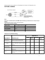
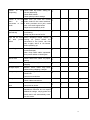
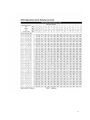
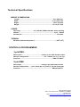
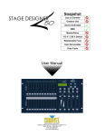
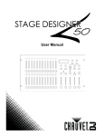
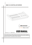
48 CHANNEL DMX CONSOLE USER MANUAL TABLE OF CONTENTS 1. Before You Begin..........................................................................................................2 What is included..............................................................................................................2 Unpacking Instructions....................................................................................................2 Safety Instructions...........................................................................................................2 2. Introduction...................................................................................................................3 Features..........................................................................................................................3 Product Overview (front)..............................................................................................4-5 Product Overview (rear panel)........................................................................................6 Common Terms...............................................................................................................6 3. Operating Instructions.................................................................................................7 Setup...............................................................................................................................7 Setting up the System.....................................................................................................7 Physical fader Assignment (optional setup).....................................................................7 Switching between Page and Page B(Channels 1-21 and 25-48)..................................8 4. Programming................................................................................................................9 Erase a Program.............................................................................................................9 Erase all Scenes.............................................................................................................9 Record Clear...................................................................................................................9 Delete a step or steps...................................................................................................10 Insert a step or steps.....................................................................................................10 Modify a step or steps...................................................................................................10 5. Playback......................................................................................................................11 Playing a Scene.............................................................................................................11 1 Playing a Scene to audio Triggering..............................................................................11 Midi Operation................................................................................................................11 Setting MIDI IN..............................................................................................................12 Setting midi out..............................................................................................................12 Receiving MIDI File Dump.............................................................................................13 Sending MIDI File Dump...............................................................................................13 6. Appendix.....................................................................................................................13 DMX Primer...................................................................................................................13 Fixture Linking...............................................................................................................14 General Troubleshooting............................................................................................15-16 DMX Dip switch Quick Reference Chart........................................................................16 Technical Specifications.................................................................................................17 2 1. BEFORE YOU BEGIN What is included ※Stage Designer controller ※DC 9-12V 500mA auto switching Unpacking Instructions Immediately upon receiving a fixture, carefully unpack the carton, check the contents to ensure that all parts are present, and have been received in good condition. Notify the shipper immediately and retain packing material for inspection if any parts appear damaged from shipping or the carton itself shows signs of mishandling. Save the carton and all packing materials. In the event that a fixture must be returned to the factory, it is important that the fixture be returned in the original factory box and packing. Safety Instructions z Please keep this User Guide for future consultation. If you sell the unit to another user, be sure that they also receive this instruction booklet. z Always make sure that you are connecting to the proper voltage and that the line voltage you are connecting to is not higher than that stated on decal or rear panel of the fixture. z This product is intended for indoor use only1 z To prevent risk of fire or shock, do not expose fixture to rain or moisture. Make sure there are no flammable materials close to the unit while operating. z In the event of serious operating problem, stop using the unit immediately. Never try to repair the unit by yourself. Repairs carried out by unskilled people can lead to damage or malfunction. Please contact the nearest authorized technical assistance center. Always use the same type spare parts. z Don't connect the device to a dimmer pack. z z z Make sure power cord is never crimped or damaged. Never disconnect power cord by pulling or tugging on the cord. Do not operate this device in more than 104°F(40°C) ambient temperature conditions. Caution! There are no user serviceable parts inside the unit. Do not open the housing or attempt any repairs yourself. In the unlikely event your unit may require service. 3 2. INTRODUCTION The Stage Designer is a universal intelligent lighting controller. It allows the control of 48 channels with 96 scene/chase playback faders. Each scene/chase can contain up to 1000 individual steps, or looks. On the surface, when in the CHASE◄►SCENE mode, there are 12 physical faders for the playback of the saved programs. There are 4 pages of Scenes playback on Page A, and an additional 4 pages of playback faders on Page B. Programs can be triggered by music, midi, automatically or manually. Channel assignments can be reprogrammed for ease of controlling different fixtures. On the surface you will find various programming tools such as 24 channel fader, A/B master faders for cross mixing, and Fade and Speed time faders for on the fly adjustments. And it also has an LED display for easy navigation of controls and menu functions. Features z Universal DMX-512 controller z z z z z z z z z z z z z z Controls up to 48 DMX channels 8 pages of 12 playbacks faders 6 sets of chases containing 240 scenes Program fade and speed time into each step Reversible sliders Re-assignable channels Sequential linking of chases Assignable joystick Fog $ strobe control buttons Grab any fixture on the fly Beat activation, tap-sync and auto run Polarity selector 6 space(6U) 19" rack mount MIDI compatible 4 Product Overview(front) ITEM Button or Fader Function 1 Channel Faders Indicates channels 1-12(25-36) 2 Channel Flash button Brings the relevant fader to 100% or DMX value of 255 3 Channel Faders Indicates channels 13-24(37-48) 4 Scene Playback indicators Indicates that the scene is playing back 5 Channel Flash button Brings the relevant fader to 100% or DMX value of 255 6 Down/Beat Rev Down functions to modify a scene in edit mode, Beat Rev is used to reverse the chasing direction of a program with regular beat. 7 Up/Chase Reverse Up function to modify a scene in Edit mode, chase Reverse is used to reverse the chasing direction of a program under Speed Slider control. 8 LCD Display Shows the current activity or programming state 9 Delete/Rev One Delete a step in a scene or reverse the chasing direction of any program 11 Insert % or 255 Insert is to add 1 step or steps into a scene; %or255 is used to change the display value cycle between % and 0-255 13 Edit/All Rev Edit is used to activate Edit mode; All Rev is to reverse the chasing direction of all programs 14 Record/Shift Record is used to activate Record mode or program a step; Shift functions the alternate function of other 5 buttons only 15 Audio/Page A_B Audio activate audio sync of chase; Page A_B switches the channel faders BETWEEN 1-24 MODE AND 25-48 MODE. Press and hold Record & Page A_B to switch between the 2 channel pages 16 Blind Take the channel out of a program temporarily in Chase ◄►Scene mode used to temporarily blackout overall output 17 Dark Used to temporarily blackout overall output 18 Home Used to deactivate the Blind on a given channel 19 Park Used to select Single/Mix Chase, bring Channel 13-24(37-48) to full of current setting, or momentarily program a scene into Master B slider depending on the current mode 20 Mode Select/ Rec Speed Used to activate the operating mode; Rec Speed sets the speed of any programs chasing in Mix mode 21 Tap Sync Repeatedly tapping this button will establish the chase speed 22 Hold Used to momentarily maintain current scene 23 Page Tap to select pages of scenes from 1-4(Page A) and 1-4(Page B) 24 Full On Momentarily bring all channels (1-48) to full intensity 25 Step Used to go to the next step when the Speed slider is set in Show Mode or in Edit mode 26 Add Kill/ Rec exit In Add mode, multiple scenes or Flash buttons will be on at the same time; In kill mode, pressing any Flash button will kill any other scenes or programs; Rec Exit is used to exit from Program or Edit mode 27 Blackout Used to kill all output, with exception of Full On 28 Audio Level Fader Adjusts the audio sensitivity when in Audio trigger mode of scenes 29 Speed Fader Used to adjust the speed of scenes/chases running 30 Fade Fader Adjusts the fade-in, fade-out, and cross-fade times 31 Master A_B Adjusts overall intensity Product Overview (rear panel) 6 ITEM Button or Fader Function 1 3-pin DMX output connector DMX control signal 2 5-pin DMX output connector DMX control signal 3 Polarity switch Used to select DMX polarity 4 MIDI Thru MIDI port for connecting to a sequencer or MIDI device 5 MIDI Out MIDI port for connecting to a sequencer or MIDI device 6 MIDI In MIDI port for connecting to a sequencer or MIDI device 7 Audio Input This jack accepts a line level audio input signal ranging from 100 mV to 1Vpp 8 Remote Input Blackout and Full On may be controlled by a remote control using a standard 1/4" jack 9 DC Input DC 12-20V, 500mAMin Common Terms The following are common terms used in intelligent light programming. Blackout is a state where all lighting fixtures' light output are set to 0 or off, usually on a temporary basis. DMX-512 is an industry standard digital communication protocol used in entertainment lighting equipment. For more information read Sections" DMX Primer" and "DMX Control Mode" in the Appendix. Fixture refers to your lighting instrument or other device such as a fogger or dimmer which you can control. Programs are a number of scenes arranged one after another. It can be programmed as either a single scene or multiple scenes in sequence. Scenes are static lighting states. Sliders are also known as faders. Chases can also be called programs. A chase consists of a number of scenes arranged one 7 after another. Scanner refers to a lighting instrument with a pan and tilt mirror; however DMX controllers can use this term to control any DMX-512 compatible device as a generic fixture. MIDI is a standard for representing musical information in a digital format. A MIDI input would provide external triggering of scenes using midi devices such as a midi keyboard. Stand Alone refers to a fixture's ability to function independently of an external controller and usually in sync to music, due to a built in microphone. Fade slider is used to adjust the fade time between scenes within a chase. Speed slider affects the amount of time a scene will hold its state. It is also considered a wait time. Shutter is a mechanical device in the lighting fixture that allows you to block the lights path. It is often used to lessen the intensity of the light output and to strobe. Patching refers to the process of assigning faders to a DMX channel within a fixture. Playbacks can be either scenes or chases that are directly called to execution by the user. A playback can also be considered program memory that can be recalled during a show. 3. OPERATING INSTRUCTIONS Setup SETTING UP THE SYSTEM 1) Place the Stage Designer on a level surface. Note! The Stage Designer can also be rack mounted, occupying six rack spaces(6U). 2) Plug the AC to DC power supply into the system back panel and into the mains outlet. 3) Plug in your DMX cable(s) to your intelligent lighting as described in the respective fixture's manual. For a quick overview of DMX see the "DMX Primer "on page 19. 4) Reset the system using the instructions on page 11 under ERASE ALL SCENES. PHYSICAL FADER ASSIGNMENT (OPTIONAL SETUP) Use this feature to combine or unify fixture control attributes for different fixtures. For example; if you were controlling 4 moving mirrors and 4 moving yokes, the color, gobo and dimmer channels may not line up ideally on the physical faders. Use this function to re-assign the dimmer, color and gobo channels to faders 1,2 and 3. From now no you will be able to control the same attributes on all fixtures using the same fader location. This is also most useful when needing to combine all colors together. ACTION: 1. Press and hold RECORD button. 2. While holding the Record button, press the Flash button #6(3) times. 3. Press the Flash button that you wish to assign the DMX channel output to. 4. While holding Record, press the Flash button corresponding to the DMX output that you wish to assign the Fader to. 5. Repeat steps 2-3 as often as necessary. 8 6. Press and hold Record & Rec Exit to exit the mode. NOTES: All physical faders can be re-assigned to output on a different DMX channel, Faders are given a channel number and are labeled on the surface of the controller as such. You can check to see what the assignment is by pressing the Fader button of the corresponding channel while in this mode. Here is no limit to the amount of channels that can be assigned to a single faders. One can assign up to all 48 channels of DMX output to a single Fader. CHNO corresponds to the Physical Fader, while SLDNO corresponds to the DMX output channel. SWITCHING BETWEEN PAGE AND PAGE B (CHANNELS 1-24 AND 25-48) ACTION: 1) Press and hold Record & press Page A B button. If you are on Page A, then this will bring you to Page B. If you are on Page B, then this will bring you t Page A. NOTES: When the fixture turns on ,it will revert to the previously used page. Page A is used to control channels 1-24, while Page B is used to control channels 25-48. The screen will display which current page. There's an additional set of 4pages of playback controls on Page B. 4.PROGRAMMING EARSE A PROGRAM 9 Action 1) Record enable 2) Use the Page button to select the page the scene you wish to erase is on. 3) Press and hold the Edit button &tap the flash button (13-14) twice of scene you wish to erase is on. 4) Release the 2buttions.The LED for the corresponding program should light. Indicating that has been selected. 5) Pres the Delete button. All LEDS should light, indicating the program is erased. EARES ALL SCENES Action 1) Record enable 6) Press and hold RECORD 2) While holding record button tap the flash button in the following sequence:1-3-2-3.Relese the record button. 7) All LEDS should light .Indicating all program have been erased. 8) Press and hold RECORD & REX EXIT to exit the mode. Warning: This will reset the controller to its factory defaults .This will erase all program and setting. NOTES: You must be in record mode to reset the controller. The LED over the record button will light, indicating the Record mode operation. RECORD CLAEAR Action 1) Record enable 2) Record a scene with 1 or more steps. 3) If you not satisfied with the scene, you may press and hold the Record button.& tap the Page/REC CLR button. All LEDS WILL flash. indicating the scenes have been cleared. NOTES: All scenes in the temporary memory of the controller will be erased by this process. This process will not affect the scenes already. Programmed into Scene fader. DELETE A STEP OR STEPS Action 1) Ender the EDIT mode. 10 2) 3) 4) 5) Tap the Step button to scroll to the step you wish to delete .Tap the Delete button when you reach the step. You wish to delete. Repeat step 2 and 3 all of the unwanted steps have been deleted. Press and hold the Record REC Exit button. The Scene button LED will turn off, indicating that the Edie mode has been exited. INSERT STEP OR STEPS Action 1) Record a scene or scenes you wish to insert. 2) Be sure you are in Chase ◄► Scene and enter the EDIT mode. 3) Tap the Step button to scroll to the step which you wish to insert the step before. You may read the step from display. 4) Tap the Insert button to insert the step you’ve created before. 5) Exit Edit mode. NOTES: Part of entering the Edit mode is. selecting scene you wish to edit. See section on Edit enable for further instruction. All LEDS will flash to indicating a successfully Insert of the step. MODIFY STEP OR STEPS Action 1) Enter EDIT node. 2) Press and hold the UP button if you want to raise the intensity. Press the DOWN button if you want to lower the intensity. 3) 3) Tap the Step button to scroll to the step which you wish to insert the step before. You may read the step from display. 4) While holding the UP or DOWN button tap the Flash button corresponding to the DMX channel of the Scene you wish to modify until you reach the desired intensity value read from the display. Then, you may tap the Flash buttons until you are satisfied with the new Scene. 5) Repeat step2, 3, and 4 until all the steps have been modified. 6) Exit EDIT mode. NOTES: Part of entering the Edit mode is selecting which scene you wish to Edit. See section on enable for further instructions. All LEDS will flash to indicate a successful insert of the step. 5. Playback This controller uses the Channel Fader and Flash buttons for multiple uses. In this occurrence, Channel Fader 13-24(37-48) are used playing back of scenes already recorded. This is only when the controller is the Chase◄► scene mode. In this instance, Master Fader 11 A will control the manual fader controls, whish Master Fader B will control the Scenes being played back. PLAYING A SCENE A Scene can contain 1000steps. The term steps and scene are used interchangeably. Action Tap the ode select button to select Chase ◄► SCENE MODE. Tap the page to select the correct page the program you wish to run is located. Push master Slider B to its maximum position(fully down) Move the desired Channel slider (13-24) to its maximum and the Scene will fader in depending upon current fade time. 5) Move the channel Slider to adjust the output of the current program. NOTES: The current mode is indicated by the 3 ALEDS. Red is the Chase ◄►scene. Yellow is 2-scene preset a/b, And, Green is 1-24 single mode. You may press and hold down the relevant Flash button for Scene to trigger the button Momentarily. 1) 2) 3) 4) PLAYING A SCENE TO AUDIOTIGGERING Action 1) Select your Scene as described in the above section. 2) Tap the Audio button until its LED lights, indicating AUDIO mode is active. 3) Use the Audio Level slider to adjust the sensitivity. 4) To return to normal mode, tap the Audio button a second time, causing its LED to go out. AUDIO mode is disengaged. NOTES: This is the process of using the built-in-microphone, or using the audio jack on the controller to use an alternative audio source for triggering of Scenes. MIDI Operation The controller will only respond to MIDI commands on the MIDI channel that it is assigned to. All MIDI control is performed using Note on the commands. All other MIDI instructions are ignored. To stop a chase, send the blackout on note. Setting MIDI IN Action 1) While holding down the RECORD button, simultaneously tap to Flash button #1 three times. The 12 display reads MIDI CHANNEL IN to indicate channel setup is available. 2) Select the MIDI control channel (1-16) by tapping Flash button 1-16. The relevant channel LED lights indicating MIDI IN channel is set. 3) While holding down RECORD, tap the REC EXIT button to exit MIDI setting. MIDI Note FUCNCTION(TURN ON/OFF) 27-69 Turn on or off program1-48 70-93 Activate Channel 1-24 94 FULL-ON 95 DARK (momentary blackout) 96 HOLD 97 Turn on or off AUDIO 98 Chase ◄► SCENE 99 MODE:1-12A_1-12B 100 MODE:1-24A 101 Step 102 BLACKOUT Notes: This is the Channel that the controller will receive MIDI note commands. Notes: When working with MIDI notes 22-93, you may simulate a fader’s increase and decrease by adjusting the velocity of the node. Setting MIDI OUT Action 4) While holding down the RECORD button, simultaneously tap Flash button #2 three times. The display reads MIDI CHANNEL OUT to indicate channel setup is available. 5) Select the MIDI control channel 91-16)by tapping Flash button 1-16. The relevant lights indicating MIDI OUT channel is set. 6) While holding down RECOR, tap the REC EXIT Button to exit MIDI setting. Notes: This is the Channel that the controller will transmit MIDI note commands. Receiving MIDI File Dump Action 7) While holding down the RECORD button, simultaneously Flash button #3 three times. The display reads MIDI FIEDOUMP RECVING 000%wen the device is in the correct mode. 8) While holding down RECORD, tap the REC EXIT button to exit MIDI setting. Notes: This is the process of copying your entire show to another TFX-48B. This will not work with any other device. 13 This process can take several minutes to complete. This control will automatically being sending the PILE DUMP once the mode has been selected. Therefore, be sure that the other deceive has previously been setup to receive the transfer. During FILE DUMP, all other operation will cease to function. If errors or power failure occurs, FILE DUPM will be interrupted and stop. Sending MIDI File Dump Action 9) While holding down the RECORD button, simultaneously tap Flash #4 three times. The display reads MIDI FILEDUMP SENDING 000%when the device is in the correct mode. 10) While holding down RECORD, tap the REC EXIT button exit MIDI setting. Notes: This is the process of copying your entire show to another TFX-48B.This will not work with any other device. This process can take several minutes to complete. The control will automatically being sending the FILE DUPM once the mode has been selected. Therefore, be sure that the other device has previously been setup to receive the transfer. During FILE DUMP, al l other operations will cease to function. If errors or power failure occurs, FILE DUMP will be interrupted and stop. 6. APPENDIX DMX Primer There are 512 channels in a DMX-512 connection. Channel may be assigned in any manner. A fixture capable of receiving DMX 512 will require one or a number of sequential channels. The user must assign a starting address on the fixture that indicates the first channel reserved in the controller. There are many different types of DMX controllable fixture and they all may vary in the total number of channels required, Choosing a start address shout be planned in advance. Channel should never overlap. If they do, this will result in erratic operation of the fixture whose starting address is set incorrectly. You can however, control multiple fixture of the same type using the same starting address as long as the intended result is that of unison movement or operation. In other words, the fixture will be slaved together and all respond exactly the same. DMX fixtures are designed to receive data though a serial Daisy Chain. A Daisy Chain connection is where the DATA OUT of one fixture connects to the DATA IN of the next fixture. The order in which the fixtures are connected is not important and has no effect on how a controller communicates to each fixture. Use an order that provides for the easiest and most direct cabling. Connect fixtures using shielded two conductor twisted pair cable with three pin XLR male to female connectors, The 14 shield connection is pin 1,while pin 2 is Data Negative (S-) and pin 3 is Data positive (S+) FIXTURE LINKING Note! If you use a controller with a 5 pin DMX output connector, you will need to use a 5 pin to 3 pin adapter. The chart below details a proper cable conversion. 3 Pin to 5 pin conversion channel CONDUCTOR 3 Pin FEMALE (OUTPUT) 5 Pin GROUN/SHIELD Pin 1 Pin 1 DATA(-)SIQNAL Pin 2 Pin 2 DATA(+)SIQNAL Pin 3 Pin 3 DO NOT USE DO NOE USE DO NOT USE DO NOE USE General Troubleshooting Applies to lights Foggers & Snow controllers Dimmers& chaser Symptom Solution(s) Auto shut off Check fan thermal switch reset Beam is very dim or not bright Clean optical system or replace lamp Check 220V/110V switch for proper setting Breaker/Fuse keeps blowing Check total load placed on device Chase is too slow Check users manual adjustment for speed √ √ √ Device power Check for power on mains. Check device’s fuse.(internal and/or external) √ √ √ has no √ √ √ 15 Fixture is responding not Check DMX Dip switch setting for correct addressing Check DMX cables Check polarity switch settings √ Fixture is on but Make sure you have the correct there is no audio mode on the control switches. movement to the If audio provided via1/4 jack, make audio sure a live audio signal exists Adjust sound sensitivity knob. √ Lamp cuts sporadically Possible bad lamp or fixture is overheating. Lamp may be at end of its life. √ Light will not come Some discharge lamps require a on after power cooling off period before the failure electronics in the fixture can kick start it again, wait 5 to 10 minutes before powering up. √ Loss of signal Use only DMX cables Install terminator Note: Keep DMX cables separated from power cables or black lights. √ Moves slow Check 220V/110V switch for proper setting √ No flash Re-install bulb, may have shifted in shipping √ No light output Bounce mirror motor may have shifted during shipping, readjust √ No light output Check slip ring & brushes for contact install bulb Call service technician √ Relay will not work Check reset switch Check cable connections Remote does not work Make sure connection connected to device Stand alone mode All Chauvet lighting fixtures featuring standalone functions do not require additional settings, simply power the fixture and it will automatically enter into this mode off √ √ √ √ √ is firmly √ √ √ 16 17 Technical Specifications WEIGHT & DIMENSIONS Length………………………………………………………………..19 in (483 mm) Width………………………………………………………………..10.5 in (267 mm) Height…………………………………………………………………305 in (89 mm) Weight……………………………………………………………….10.3 in (4.7 mm) POWER Operating…………………………DC 12V-18V 500Ma 100-240v autos witching Adapter……………………………………………………………..……2-pin Edison Internal fuse………………………………………………………………….FO.5A 25 THERMAL Maximum ambient temperature……………………………………......1040F (400) CONTROL & PROGRAMMING 3-pin DMX: Data output…………………………………..…locking 3-pin XLR female socket Data pin configuration………………………….…pin 1 shield, pin 2 (-), pin 3(+) Protocols......................................................................................DMX-512 USITT 5-pin DMX: Data output………………………….………….locking 5-pin XLR female socket Data pin configuration…….pin 1 shield, pin 2 (-), pin 3(+), pin 4+5 (not used) Protocols................................................................................... DMX-512 USITT Lighting Underground 341 ½ East Arbor Street, Long Beach, CA 90805 714-618-2519 Web: http://www.lightingunderground.com E-Mail: [email protected] 18