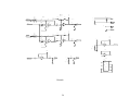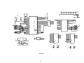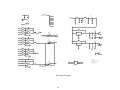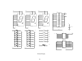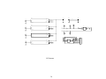
1
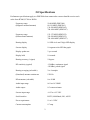
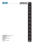
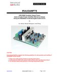
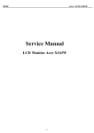
SERIES 5900
RADIO DIRECTION FINDER
USER MANUAL
DDF5911A DF Processor
DDF5921A Remote Display
DDF5950A/5960A RF Summer
0
315
45
270
90
225
135
180
AVG
ATTEN
VOL
DIM
CAL
VOL
DOPPLER SYSTEMS INC.
PO Box 2780
37202 N. Bloody Basin Rd.
Carefree, Arizona 85377
Tel: (480) 488-9755
Fax: (480) 488-1295
Copyright 8 1999, Doppler Systems Inc. All rights reserved. Rev. A - Issue 2002/11.
Warranty Information
Doppler Systems Inc. will repair or replace, at their option, any parts found to be defective in either
materials or workmanship for a period of one year from the date of shipping. Defective parts must
be returned for replacement. In the US, contact the factory, or overseas your local distributor, for
advice about returning any defective parts or equipment.
If a defective part or design error causes your radio direction finder to operate improperly during the
one-year warranty period, Doppler Systems Inc. will service it free of charge if returned at owner’s
expense. If improper operation is due to an error on the part of the purchaser, there will be a repair
charge.
Doppler Systems Inc. are not responsible for damage caused by the use of improper tools or solder,
failure to follow the printed instructions, misuse or abuse, unauthorized modifications,
misapplication of the unit, theft, fire or accidents. This warranty applies only to the equipment sold
by Doppler Systems Inc. and does not cover incidental or consequential damages.
Doppler Systems radio direction finding equipment is designed to help locate the source of
interfering, emergency or unauthorized transmissions, or others coming from marker and rescue
beacons, etc., and is not intended to be used as a navigation aid. In particular it is not to be used
for aircraft or marine navigation.
Accessories Included
With the DDF5911 processor assembly:
(1) User Manual
(1) Cigar lighter to 2.5 mm dc power plug cable #DDF6110
(1) 3.5 mm phone plug to 3.5 mm phone plug cable #40DK40
(1) 3.5 mm phone plug to RCA phono plug cable #40DK25
(2) 3.5 mm phone plug #750
(1) 2.5 mm dc power cable #4201
With the DDF5921 display assembly:
(1) DB9S to DB9P cable #DDF6203
(1) Windshield mounting kit
With the DDF5950 or DDF5960 RF summer assembly:
(1) Control cable #DDF6119
(1) Coax cable #DDF6116
Table of Contents
1.0 Introduction ...............................................................................................................................1
2.0 Specifications.............................................................................................................................2
3.0 Controls and Connectors............................................................................................................4
4.0 Installation ...............................................................................................................................10
5.0 Operation..................................................................................................................................14
6.0 PC Control and Advanced Topics............................................................................................16
7.0 Servicing .................................................................................................................................23
1.0 Introduction
The Series DDF5900 is a high performance radio direction finding system that operates using the
simulated Doppler principle in which the outputs of a circular array of antennas are combined in a
way that simulates a single element rotating in a circular path. As the simulated element approaches
the wave front of an rf signal, the frequency of its output increases due to the Doppler effect, and as
it recedes from the transmitted source, the frequency decreases. The amount of frequency change
(deviation) is related to the speed of rotation and the diameter of the antenna array, while the
modulation frequency is equal to the frequency of rotation (the antenna sweep frequency). When
connected to a narrow band communication receiver, the sweep frequency is present on the audio
output. To obtain the bearing angle, the direction finder processes this audio output.
Many features are present in the Series DDF5900 comprising the 5911A processor, 5921A display
and 5950A or 5960A rf summer:
C
A small remote display unit puts the bearing and signal strength LEDs and all controls close
to the operator. It can be conveniently mounted on a vehicle windshield.
C
A remote rf summing unit eliminates the need for matched coaxial cables and provides
broadband frequency coverage from 50 to 1000 MHz.
C
Advanced signal processing is used to detect the signal with the receiver either squelched or
unsquelched. Both continuous and 150 millisecond pulsed signals can be processed.
C
The sweep direction automatically reverses from clockwise to counterclockwise to
compensate for asymmetries in the receiver.
C
An internal audio amplifier and loudspeaker are provided for monitoring the signal, and a
sharp notch filter removes the sweep frequency for clarity.
C
The remote display can be replaced by a PC using a standard RS232 connection. The PC can
then be used to select optional bearing processing parameters (pulse correlation intervals,
etc.) which are retained in non-volatile memory.
C
All electronics are housed in metal enclosures for durability and enhanced electromagnetic
compatibility (EMC). Antennas are constructed of corrosion resistant materials and are
designed for wind speeds up to 45 m/s (100 mph).
1
2.0 Specifications
Performance specifications apply to a DDF5900 when connected to a narrow band fm receiver such
as the Icom R7000, R7100 or R8500.
Frequency range
(Magnetic mounted antenna)
50-88 MHZ (DDF5968)
88-136 MHZ (DDF5961)
136-500 MHZ (DDF5962)
700-1000 MHZ (DDF5967)
Frequency range
(Mast mounted antenna)
125-175 MHZ (DDF5952)
350-500 MHZ (DDF5955)
700-1000 MHZ (DDF5957)
Bearing display
16 LED circle and 3 digit LED display
S-meter display
10 segment color LED bar graph
Display update rate
2 per second
Display hold
10 seconds
Bearing accuracy (1 sigma)
5 degrees
DF sensitivity (typical)
-126 dBm, continuous signal
-120 dBm, pulsed signal
Bearing averaging (selectable)
2 or 4 samples
(Simulated) antenna rotation rate
1229 Hz
RF attenuator (selectable)
0 or 20 dB
Audio input range
0.01 to 0.6 VRMS
Audio output
0.5 watts maximum
S-meter input range
+0.25 to +8.5 VDC
Serial interface
RS232, 4800 Baud, 8N1, ASCII
Power requirement
11 to 14 VDC
Current consumption
0.7 amp
2
Operating temperature
0 to 50 degrees C (display and processor)
-50 to 100 degrees C (rf summer and antenna)
Dimensions
(processor - H x W x D)
(display - H x W x D)
(Rf summer - H x W x D)
32 x 216 x 140 mm (1.25 x 8.5 x 5.5 in)
60 x 114 x 32 mm (2.375 x 4.5 x 1.25 in)
57 x 102 x 121 mm (2.25 x 4 x 4.75 in)
Weight
(processor)
(display)
(Rf summer)
0.635 kg (1.40 lbs)
0.236 kg (0.52 lbs)
0.544 kg (1.20 lbs)
3
3.0 Controls and Connectors
Figures 3-1, 3-2 and 3-3 shows the controls, displays and connectors provided on the DDF5921
remote display, the DDF5911 processor and the DDF5950/5960 RF summer . The items marked •
in the following paragraphs refer to the items shown in these figures. The values given in the
paragraphs below are those that are provided by the factory default settings, which will normally be
used. Refer to Section 6 for a discussion of alternate settings.
•1 The center yellow LED indicates that power is applied.
•2 The bearing is displayed by illumination of one of the red LEDs on the circular display.
•3 The signal strength is indicated in this 10-segment display. It should be calibrated so that the
signal strength is 1 when a very weak signal is present and 9 when a very strong signal is present. As
shipped from the factory, the S-meter and Bearing are calibrated for an Icom R8500 receiver. To
calibrate the unit for other receivers, refer to paragraph 6.5.
•4 Bearing angles in degrees are displayed in the 7-segment display. Both the circular LED display
and the digital display are held for 10 seconds after the signal disappears. To help distinguish when
the bearing is updating and when it is being held, the decimal point following the units digit
alternates ON to OFF whenever the bearing updates.
•5 Bearing data is computed twice per second. The front panel displays a moving average of the
last N bearings calculated. Normally, the number of bearings averaged is equal to 2; that is, one
clockwise and one counterclockwise. Pressing this switch causes the number of bearings averaged to
be increased from 2 to 4. Pressing it again restores the number averaged to 2. When 4 averages have
been selected, the small LED following the hundreds digit (directly above this switch) in the seven
segment display •4, is illuminated.
•6 The front panel LEDs may be dimmed by momentarily pressing this switch. Pressing it again
returns the LEDs to full brightness.
•7 Pressing this switch causes a 20 dB attenuation of the rf input to the commutation electronics.
Pressing it again removes the 20 dB attenuation. The LED next to the tens digit (directly above this
switch) on the seven segment display •4, is illuminated when the 20 dB attenuation is applied.
•8 Pressing this switch causes the bearing of the signal being received to be set to 0 degrees.
•9 Pressing this switch causes the volume to be increased in steps of 4 dB over a range of 20 dB.
Hold the switch down or press it repeatedly to increase the volume to the level desired.
4
•10 This switch reduces the volume in steps of 4 dB over a range of 20 dB.
•11 Connect to the DB9S connector on the cable supplied with the remote display. This cable
connects the remote display to the processor.
•12 J1, DC power input. Connect to +12 VDC using the supplied 2.5mm to cigar plug cable.
•13 J2, DC power output. Connect to +12 VDC receiver using the supplied 2.5mm cable. Do not
exceed 2 amps.
•14 J3, external speaker output. May be connected to an external speaker (not supplied) using one
of the supplied 3.5 mm plugs.
•15 J4, receiver audio input. Connect to the external speaker output of your receiver using the
supplied 3.5 mm to 3.5 mm cable or make a custom cable using one of the supplied 3.5 mm plugs.
•16 J5, RSS input. Connect to the receiver’s received signal strength (RSS) output using the
supplied 3.5 mm to RCA phono jack cable or make a custom cable using one of the supplied 3.5 mm
plugs.
•17 J6, remote display output. Connect to the DB9P connector on the cable supplied with the
remote display or use the same cable to connect to a PC for operation as described in Section 6.
•18 J7, antenna control cable output. Connect to the DA15P connector on the cable supplied with
the rf summer.
•19 Antenna A input. Connect to the left front antenna element.
•20 Antenna B input. Connect to the left rear antenna element.
•21 Antenna C input. Connect to the right rear antenna element.
•22 Antenna D input. Connect to the right front antenna element.
•23 Antenna control cable input. Connect to the 9 pin circular connector on the cable supplied with
the rf summer. This cable connects the rf summer to the processor.
•24 RF output. Connect to the TNC connector on the coax cable supplied with the rf summer and
connect the BNC end of this cable to the receiver’s antenna input.
5
0
315
45
270
90
225
135
180
AVG
ATTEN
VOL
DIM
CAL
VOL
Figure 3-1
Remote Display Controls, Displays and Connector
6
J1
J2
J3
J4
J5
J6
12 VDC
IN
12 VDC
OUT
EXT
SPKR
AUD
IN
RSS
IN
RS232
DISPLAY
Figure 3-2
Processor Connectors
7
J7
RF
SUMMER
Figure 3-3
RF Summer Connectors
8
4.0 Installation
4.1 Mobile installation
Four antenna elements are used for mobile operation. At frequencies below 500 MHZ, magnetically
mounted quarter wave whips are used; for operation in the 700-1000 MHZ band please see below.
The antennas must provide a good coupling to the ground plane, and must be of exactly the same
type. It is especially important that the coaxes used have the same length. Doppler Systems
antennas DDF5968, 5961, and 5962 all use the same magnetic mount base and cover the frequency
ranges 50-88, 88-136, and 136-500 MHZ respectively. Cut the whips to resonance using the chart
provided with the antennas and space them between 1/8 and 1/4 wavelength apart on the car=s roof.
To avoid damage to the input circuitry used in the rf summer, touch the antenna ground plane
before attaching the whips to the magnetic mounts. It is important that the vehicle provides at
least 1/4 wavelength of ground plane outboard of the antennas.
It is a good idea to remove any other antenna from the car when using the direction finder to avoid its
affecting the response pattern of the antenna. If you need to use another antenna, try experimenting
with its location to minimize the coupling with the DF antenna.
Do not transmit more than a few watts in the immediate vicinity of the DF antenna - especially if the
transmit frequency is in the same frequency range as that of the DF antenna. It is possible to
damage the rf summer if more that a few hundred milliwatts of rf power is induced into its
input.
Place the rf summer (DDF5960) on the car with the cables oriented towards the rear of the car.
Connect the magnetic mount antenna cables to the corresponding TNC connectors on the rf summer
(that is, the left front antenna to the left front connector, etc.). Locate the summer near the back of
the car (the lid of the trunk or boot) so that the magnetic mount antenna cables do not have excessive
slack. Secure the four antenna cables together with nylon ties so that they are not free to move
around and touch the antenna elements. Route the control and rf cables through an open window to
the direction finder and receiver.
For mobile operation in the 700-1000 MHZ band, antenna DDF5967 should be mounted directly on
top of the rf summer. This antenna provides an extended ground plane, a wind shroud, and four stub
type antennas built into TNC connectors. Place the assembled rf summer/antenna in the center of the
car roof.
Place the receiver and df processor assembly in the rear of the car and mount the remote display to
the windshield as described in the following section, 4.2. Connect all cables as shown in Figure 4-1.
Do not connect the input power until all other connections have been made, and if the power is
disconnected, wait about 10 seconds before re-applying it.
4.2 Mounting the remote display
9
The remote display is designed to be mounted on the windshield. A mounting kit is included which
permits the display to be repositioned for optimum viewing. A special silicone cement is used to
attach the mount to the windshield. (The mount and cement may later be removed if desired.)
Select a location where the display can be readily seen and the controls reached. Be sure that the
display does not interfere with your view of the road, however. One good location is near the bottom
center of the windshield. Allow room below the mount for access to the mounting screw using a
right angle screw driver.
The windshield temperature must be at least 18 deg C (65 deg F) for the adhesive to work properly.
Clean the windshield surface first using a glass cleaner, then use isopropyl alcohol to remove any
remaining residue or grease. Also clean the surface of the mounting bracket with the alcohol to
remove any finger oil or grease that will prevent a good bond. Apply a thick even coat of the
silicone cement to the back of the bracket (the larger flat side).
Hold the mounting bracket with its rounded end pointing up directly over the location you have
selected and press the bracket firmly into place. Be sure you have the correct location because the
cement will bond on contact, and the mount cannot be repositioned.
Apply a strip of tape over the bracket to maintain pressure against the windshield, and allow the
cement to cure for 24 hours before removing the tape or installing the mount.
After 24 hours, loosen the screw on the back of the mounting stem and slide the stem down over the
mounting bracket. Gently tighten the screw using a right angle screw driver if necessary. Do not
over tighten this screw.
The windshield mount may be removed from the remote display and the display mounted to a
bracket if desired. Be certain that the mounting screw used (1/4-20 thread) is no longer than 6
mm (1/4 inch) so as to avoid damaging the circuit board inside the unit.
4.3 Phone jacks
The phone jacks used on the DDF5911 are Switchcraft ATini-Jax@ connectors. These are commonly
referred to as 3.5 mm connectors, but they actually measure 3.58 mm (0.141 inch) diameter. Other
3.5 mm connectors such as are used on ICOM receivers measure closer to 3.50 mm (0.138 inch)
diameter. For reliable operation, mating plugs must be Switchcraft Type 750, which are supplied
with the DDF5911. These plugs mate with the 3.5 mm jacks used on the ICOM receivers, but the
ICOM 3.5 mm plugs do not reliably mate with the Switchcraft Tini-Jax connectors used in the
DDF5911.
Cables 40DK40 (3.5 mm to 3.5 mm) and 40DK25(3.5 mm to RCA plug) are built with the
Switchcraft 750 style plug.
10
4.4 Receiver mods for RSS output
The ICOM R7000 can easily be modified to provide an RSS output for the DDF5900. Remove the
top cover and locate the Main Unit PWB on the left side of the receiver and the spare RCA phono
jack (J7) on the rear panel. Solder a 5.1 K resistor to the center pin of J7 and solder an insulated
wire to the other end of the resistor. Route the wire to the top side of the Main Unit and carefully
solder the other end of the wire to pin 1 of IC4. IC4 is an 8 pin DIP op amplifier type NMJ4558D.
(Solder the wire directly to the IC lead using a minimum amount of heat and a very small tip iron).
On the ICOM R7100 or R8500 you can connect the S-meter input directly to the AGC output jack.
Other receivers may require adding an RCA jack and wiring to whatever op amp output is providing
the signal used for AGC or S-meter drive. Check that the signal is in the range +0.25 to +8.5 VDC
Note that the RSS input is not required for operation of the direction finder, but of course must be
present if the S-meter on the remote display is to be used.
11
B
A
C
D
Magnet Mount Antenna
DDF5961, 5962,
5967 or 5968
or Mast Mount Antenna
DDF5952, 5955 or 5957
JA
JB
JC
TNC
TNC
J7
8
15
7
14
6
13
5
12
4
11
3
10
2
9
1
JD
TNC
TNC
DDF5960 Magnet Mount
or DDF5950 Mast Mount
RF Summer
J1
J2
TNC
DDF5911
Processor
J6
DA15P
9S Circular
DDF5921
Remote
Display
5
9
4
8
3
7
2
6
1
5
9
4
8
3
7
2
6
1
DB9P
DDF6119
Control Cable
DDF6116
Coax Cable
J1
DB9S
DDF6203 Cable
J4
40DK40 Cable
3.5mm
J5
40DK25 Cable
3.5mm
4201 Cable
J2
J1
DDF6110 Cable
BNC
ANT
2.5mm
RCA
3.5mm
Ext Spkr
S-meter
Power
RECEIVER
Figure 4-1
System Cabling
12
2.5mm
Autoplug
5.0 Operation
5.1 Turn-on initialization
During the initial turn-on of the DDF5911, the calibration values that were last set are restored.
To ensure that the logic circuitry is properly reset, allow the power to remain off for about 10
seconds before restoring power.
5.2 Calibration
The bearing angle is easily calibrated from the front panel.
If you are using the direction finder in a car or boat, calibrate the bearing display so it reads 0 degrees
when receiving a signal from straight ahead. To perform this calibration, use a strong steady signal
such as a repeater output, NOAA weather station, etc. Be sure the vehicle is in an area free of
reflections with a clear line of sight to the known transmitter. While the direction finder is
displaying the bearing of the known transmitter, press the CAL switch, and the bearing should
change to 0 degrees.
For calibration in fixed-site service, please see section 6.10.
5.3 Direction finding
The simulated rotation of the antenna by the direction finder produces a tone in the receiver audio
output. You can hear this tone by removing the audio plug from the receiver external speaker output.
The tone is removed by filtering in the direction finder so that you will not hear it at the direction
finder speaker output.
The direction of simulated rotation is reversed every 2 second. This feature allows non-linearities in
the receiver to be compensated by averaging consecutive bearing readings. In normal operation, two
bearings are averaged, and if the AVG button is pushed, this is increased to 4. You may be able to
hear a click when the direction of rotation is reversed.
The DF measures the magnitude and the phase of the tone every 10 milliseconds and calculates
bearing angle from this data every 2 second.
The DF software determines whether a signal is present by examining the statistics of the sweep
frequency data. If the average amplitude of the tone exceeds the variation of the data about the
average, then it is concluded that a signal is present and a best estimate of the bearing is displayed.
This technique makes the system independent of the receiver’s volume control setting, so the
receiver’s volume may be set at any comfortable level. For best operation, set the volume to
maximum on the remote display, then increase the receiver’s volume control until just before it
sounds distorted. Then control the listening level by setting the volume on the remote display.
13
The receiver’s squelch can be set normally, or it can be opened so that the receiver is unsquelched.
If no signal is present, the DF will detect this condition from the lack of a stable sweep tone, and will
not update the display. For maximum sensitivity the system should be operated with the receiver
unsquelched. If the noise between transmissions becomes irritating, reduce the volume at the remote
display or set the receiver’s squelch for normal operation.
The front panel display updates twice every second. Bearings are retained for 10 seconds, then the
display is blanked. To distinguish an updated bearing from a retained bearing of the same value, the
decimal point on the units display alternates ON and OFF whenever the display is updated.
The preamplifiers used in the direction finder antenna electronics have a gain of about 13 dB and a
noise figure of about 3.6 dB. These are very broad band devices which can generate intermod
products if very strong input signals are present. Depending on the location of the antenna and the
frequency band being used, you may notice an increase in the noise level of the receiver which is due
to mixing of two strong input signals (for example, a broadcast fm station and a television video or
audio signal). The intermod can be reduced by enabling the attenuator switch on the direction finder
which applies 20 dB attenuation between each antenna element and its associated preamplifier.
The attenuator can also be used to extend the range of the S-meter. When the tracked signal becomes
very strong such that all 10 segments on the S-meter are illuminated, push the ATTEN button. This
will reduce the S-meter by about 7 segments.
5.4 Homing
When the direction finder is used to home on a signal source, the following guidelines should be
followed.
Take an assistant with you. Don’t try to read the display and drive at the same time.
Be sure to dim the display when using the system at night.
Try to keep out of high multipath areas (buildings, etc.) as long as possible.
Avoid strong interfering signal locations (broadcast stations, etc.)
Keep moving when the signal is present. Multipath averages out spatially (not temporally).
14
6.0 PC Control and Advanced Topics
6.1 Introduction
You should not need to use a PC with the DDF5900, but there are special situations that may require
it. The most common of these is to recalibrate the S-meter for a specific receiver and to calibrate a
fixed site station.
6.2 Serial Interface
A lap top or desk top PC may be connected to the 9-pin connector J6 using the cable provided with
the remote display or any standard straight through cable. When used with a PC, only the TXD, RXD
and GND wires are used. To listen to the audio when using a PC, you will need to connect an
external speaker at J3.
Be sure to disconnect the power from the unit at J1 before disconnecting the remote display and
connecting the PC.
Run the HyperTerminal program found under the Accessories programs in Windows 95 or 98. Set up
HyperTerminal as follows:
File Properties | Phone Number = Direct to Com 1, 2, 3 or 4 (whichever you are using).
Configure (Port Settings): Bits per second = 4800, data bits = 8, parity = none, stop bits = 1, flow
control = none.
Settings: Emulation = ANSI.
ASCII Setup, ASCII Sending: Send line ends with line feeds, echo typed characters locally, line
delay = 0, character delay = 0.
ASCII Setup, ASCII Receiving: Append line feeds to incoming line ends, wrap lines that exceed
terminal width.
Click on OK and return from the file properties to the program screen. If necessary, select Connect
from the CALL menu. With the direction finder powered, enter A1@ followed by the AEnter@ key.
You should receive the response AOK@. If you do not get this response, check the connections and
settings.
6.3 Bearing Data sent from the direction finder to the PC
With a signal tuned in, the direction finder sends a single character message followed by a carriage
return for the S-meter and a three character message followed by a carriage return for a bearing
message. The characters used are standard ASCII (hex 31 = >1=, etc.). When the signal strength is 10,
the ASCII character >:= (hex 3A) is sent.
15
These message alternate as long as a signal is being received, so the display should look something
like:
005
8
006
9
005
:
etc.
Note that all other messages sent from the direction finder to the PC have either 2 characters (for
example, AOK@) or are longer than 3 characters.
6.4 Commands from the PC to the direction finder
All commands consist of a command number followed by a carriage return obtained by hitting the
Enter key. Valid commands are listed in Table 6-1
Some of these commands are permanent and retained in the non-volatile memory so that they remain
in effect when the PC is disconnected and the remote display is reconnected. Others are temporary
and not retained. Temporary values are indicated in italics.
Permanent values over ride the factory default values which are initially stored in the non-volatile
memory. These factory default values can always be restored by issuing command 28, however. The
values used for factory default are indicated in bold print in Table 6-1.
When a valid command is sent to the direction finder, it usually answers with the response AOK@. If a
non-valid command is sent (for example, A10@), the response will be ANG@.
Requests for messages such as commands 31, 32, or 33 are answered by a longer text message that is
self explanatory.
6.5 Calibrating the S-meter
Tune in a continuous signal that has a signal strength of 9 on your receiver’s S-meter. Send
command 22 to the direction finder. (As the command is typed on the PC, the echoed characters will
be interspersed with the bearing data being received from the direction finder, making the screen
appear confusing. Do not worry about this; the serial interface is full duplex, and the command
should be received properly and acknowledged by an AOK@.)
Now tune in a very weak signal - one that is indicated by a signal strength of 1 on your receiver’s Smeter. Send command 21 to the direction finder. This completes the calibration of the S-meter.
16
6.6 Direction finding in the pulse mode
The pulse mode logic has been optimized for a pulse duration of 150 milliseconds and a period of
0.5 second. This type of pulse is frequently generated by the type of transmitter or beacon used for
vehicle tracking. It is possible to change the pulse duration and period to other commonly used
values. Enter the pulse mode by sending command 17.
As in the continuous mode, the processor again samples the sweep frequency data every 10
milliseconds and calculates the bearing angle each 0.5 second. To determine whether a signal (pulse)
was present during the 0.5 second interval, a correlation calculation is made. The amplitude of the
tone is calculated over every 150 millisecond subinterval and the subinterval with the highest value
is noted. The amplitude is then calculated over the 350 millisecond interval that does not include the
selected 150 milliseconds. The two averages are then compared, and if a criterion is exceeded, it is
concluded that a pulse occurred during the display interval. The bearing angle is then calculated
from the phase of the tone data in the selected 150 millisecond interval.
This method permits the receiver volume to be adjusted without affecting the bearing, and the
receiver squelch can be set normally or left open. Maximum sensitivity is obtained with the receiver
unsquelched.
In the pulse mode, the antenna rotation direction remains constant. That is, it does not alternate
between clockwise and counterclockwise.
Consecutive bearings may be averaged. However, the number should probably be kept at 1 in this
mode; that is, not averaged. See Section 6.7 for a discussion of changing the number of averages.
Commands 72 through 76 are used to select the display update rate and maximum pulse repetition
rate. Commands 81 through 83 similarly are used to select the pulse ON time in the correlator. For
example, command 74 followed by command 81 selects the default values of 150 msec every 0.5
second.
6.7 Setting the number of averages
The number of bearing and S-meter measurements which are averaged for display can be set directly
using commands 11 through 15. Note, however, that this is a temporary selection and is not retained
when the unit is turned off. It is useful in experimenting with the averaging to determine what value
is most useful for a given situation.
The software permits two averaging values to be stored in non-volatile memory and the direction
finder can then be toggled between these two values using commands 1 and 2 (which are issued by
pressing the AVG switch on the remote display unit).
17
The lower of the two values can be set to either 1 or 2 using commands 60 and 61, respectively. The
higher of the two values can be set to 2, 4, 10 or 20 using commands 62 through 65. These selections
are stored and will be retained when the unit is turned off. The direction finder will be initialized to
the lower of the two stored values when power is subsequently applied.
6.8 Selecting an alternate sweep rate
The default antenna sweep rate of 1229 Hz has been found to be a very good choice for most
applications. It is possible to select an alternate value, however, using commands 41 through 48. This
might be desirable if, for example, the transmitted audio has a large component at or very near 1229
Hz.
6.9 Selecting an alternate display blanking interval
The display blanks after 10 seconds if no signal is detected. This interval may be changed using
commands 51 through 56.
6.10 Calibrating the bearing to a specific value
Command 5 is used to calibrate the bearing to the straight ahead or 0 degree position. If the system is
being used at a fixed site, you should calibrate it so that 0 degrees is North. In that case, a known
signal used for calibration might have any value between 0 and 359 degrees. Commands 100 through
459 can be used to calibrate the direction finder to any number in this range.
6.11 Changing the signal to noise threshold
This threshold is set by default to 1.2 which has been found to provide a high sensitivity with a low
Afalse alarm@ rate; that is, very few bearings are displayed when there is no signal. This value can be
change to any number between 0 and 2.0 in steps of 0.1 using commands 460 through 480.
6.12 Other commands
Most of the other commands are used during factory testing, or were used for design optimization.
You are free to experiment with these, and if you ever get Alost@, you can easily restore the system to
its original default settings using command 28.
18
Table 6-1
Serial Commands
Command
Number
Description of Command. Default values shown in bold. Temporary
assignments shown in italics.
1
Number of averages = Low value
2
Number of averages = High value
3
Attenuator = OFF
4
Attenuator = ON
5
Calibrate the bearing to 0
6 through 10
Not defined
11
Number of averages = 1
12
Number of averages = 2
13
Number of averages = 4
14
Number of averages = 10
15
Number of averages = 20
16
Continuous df mode = ON
17
Pulse df mode = ON
18 through 20
Not defined
21
Calibrate S-meter to 1
22
Calibrate S-meter to 9
23 through 25
Not defined
26
Self test mode = OFF
27
Self test mode = ON
28
Set factory defaults
29 through 30
Not defined
31
Send hardware identity message
32
Send software identity message
33
Send stored parameter message
34 through 40
Not defined
19
Command
Number
Description of Command. Default values shown in bold. Temporary
assignments shown in italics.
41
Sweep rate = 2458
42
Sweep rate = 1229
43
Sweep rate = 819
44
Sweep rate = 614
45
Sweep rate = 492
46
Sweep rate = 410
47
Sweep rate = 351
48
Sweep rate = 307
49
Sweep rate = 0
50
Not defined
51
Blank time = 5 sec
52
Blank time = 10 sec
53
Blank time = 20 sec
54
Blank time = 30 sec
55
Blank time = 1 min
56
Blank time = 5 min
57
Not defined
58
Mute speaker
59
Enable speaker
60
Low value for averages = 1
61
Low value for averages = 2
62
High value for averages = 2
63
High value for averages = 4
64
High value for averages = 10
65
High value for averages = 20
66 through 71
Not defined
20
Command
Number
Description of Command. Default values shown in bold. Temporary
assignments shown in italics.
72
Display update and pulse rep rate period = 1.5 seconds
73
Display update and pulse rep rate period = 1.0 seconds
74
Display update and pulse rep rate period = 500 msec
75
Display update and pulse rep rate period = 450 msec
76
Display update and pulse rep rate period = 400 msec
77
Display update and pulse rep rate period = 660 msec
78
Display update and pulse rep rate period = 840 msec
79
Display update and pulse rep rate period = 1100 msec
80
Display update and pulse rep rate period = 1300 msec
81
On time of pulse correlator = 150 msec
82
On time of pulse correlator = 180 msec
83
On time of pulse correlator = 200 msec
84
On time of pulse correlator = 40 msec
85
On time of pulse correlator = 50 msec
100 through 459
Calibrate the bearing to the value given by the command number - 100. For
example, command 101 calibrates the bearing to 1 degree.
460 through 480
Set the signal to noise ratio threshold used in the continuous mode to the
value given by the (command number - 460)/10. For example, command
472 sets the threshold to 1.2
481 through 998
Not defined
999
Reset processor
21
7.0 Servicing
7.1 Schematics
A complete set of schematics is provided at the end of this section as an aid to troubleshooting and to
clarify interfaces. Because the DDF5900 is a microprocessor based system that uses high density
surface mount technology in the rf summer and remote display units, it is recommended that it be
returned to the factory for repair. The only exception is for upgrading of the program EPROM which
is described below.
The circuitry used in the DDF5900 is susceptible to electrostatic discharge. Observe proper ESD
precautions when servicing the unit.
Overseas customers should refer to the relevant Doppler Distributor.
7.2 EPROM replacement
Remove the bottom cover from the processing unit (DDF5911) by unscrewing the four flat head
screws on the bottom.
Replace the EPROM U103 using proper IC removal and insertion tools and observe electrostatic
discharge precautions.
22
T113
PINK
Bandpass Filter
GAIN = 2
Q=5
Audio Compressor
R134
49.9K
R133
10K
T110
BLU
R131
T111
GRN
100K
Bandpass Filter
GAIN = 2
Q = 20
C155
T114
RED.
.1/5%
C152
U118A
C156
8
V+
2
T115
BRN
RECT IN
6
R137
BP
VA+
VD+
AGD
VDVA-
R135
5.11K
3
2
7
8
15
13
14
13
100FCOM
LM324
V+
+4.0V
7
U119D
MAX4521
11
8
7
6
BP
DEM_AUD
+4.0V
X
16
9
10
C151
.1/5%
18
19
N/AP/HP
INV
LP
CLK
S1
U111
3
13
14
15
12
1
5
2
4
X0
X1
X2
X3
X4
X5
X6
X7
C159
1.0/35V
AUD_OFF
+4.0V
100FCOM
C185
1.0/35V
U119C
MAX4521
5.11K
U117B
17
20
11
16
12
NE570
R139
10K
R130
49.9K
14
MF10
1
RECT CAP
N/AP/HP
22K
4
GNDA
R3
.1/5%
V+
INV
LP
CLK
S1
50/100/CL
SAB
LSH
5
INV IN
C157
+4.0V
R138
22K
C149
.1/5%
U112D
U117A
4
1
10
5
12
6
9
100FCOM
7
OUT
R132
R136
25.5K
.1/5%
THD TRIM
13
180/5%
C154
.1/5%
3
DEL GAIN
Commutative Filter
V-
A
B
C
+4.0V
MF10
8x0.1/5%
VCC
U119
+5V
C111
.1
6
11
10
9
INH
V+
C126
C127
C128
C125
C133
C131
C134
C132
DGND
FCOM
2FCOM
4FCOM
MAX4051A
SELFTST\
U116
V+
Analog Switch
U104
U103
U106
U101
U102
U105
C166
C135
C150
C162
C158
C153
C129
.1
.1
.1
.1
.1
.1
.1
+9V
T116
R141
R140
49.9K
1.0K
WHT
EA
V-
AGND
R1
+4.0V
JP104
25.5K
R150
100K
R151
12.4K
C1
.1/5%
C168
.1/5%
R152
4
1
10
5
12
6
9
50FCOM
+4.0V
50FCOM
R153
10/1W
Note 1
R147
C165
.1/5%
Fcom Notch, Q = 8
U121A
12.4K
AUDIO_IN
V+
3
2
7
8
15
13
14
N/AP/HP
INV
LP
CLK
S1
50/100/CL
SAB
LSH
100K
R148
BP
VA+
VD+
AGD
VDVA-
V+
1
2
3
12.4K
U116D
MAX394
2Fcom Notch, Q = 8
U121B
R149
12.4K
100FCOM
+4.0V
17
20
11
16
+4.0V
R146
25.5K
17
18
19
N/AP/HP
INV
LP
CLK
S1
Audio Amplifier
(V+,GNDA)
3x1LM
Note 3
BP
19
C160
220/25V
6 1
3
7
2
R145
1.0K
Note 4
MUTE
MF10
U120
C163
.1/5%
18
20
C161
.1/5%
4 8
C164
10/25V
EXT_SPKR
5
LM386
R143
2.7
MF10
M01
MCLK
VCC
C116
18/5%
C117
18/5%
Bell 202 Modem
OMIT
Y2
3.5795MHz
X2 2
M01
M01
3
4
C167
R117
R119
AI
.1/5%
102K
102K
5
6
7
C130
120/5%
MINTR\
U108
X1 1
8
XTAL
VDD
XTAL
RDY
M0
DET
M1
RXD
RXIN
CLK
RXAMP
TXOUT
VSS
MX614
X1 1
TXD
RXEQ
VBIAS
Note 2
16
X2 2
R101
15
14
MINTR\
3
VCC
MDET
13
MDAT
12
MCLK
100K
5
MDET
6
MDAT
MCLK
7
VCC
8
11
10
9
VCC
C113
9
10
.1
C114
OMIT
Audio Processing
23
XTAL
XTAL
TXS
TX
TXD
2
1
4
U107
VCC
R106
N
C
N
C
MSK Modem
C110
TAU
CKR
BP
RXE
VBIAS
OMIT
D106
1N3600
19
VCC
18
BPS2
17
RXS*
RX
CD*
CDO*
UDO
MINTR\
Receiver & Remote Display
R159
JP102
VIN
5.11K
V+
VCC
15
AI
14
MDET
13
MDAT
12
OMIT
CD
16
BPS1
TXE
20
D107
1N3600
W101
13
11
9
7
5
3
1
7x2RM
14
12
10
AUDIO_IN
8
6
4
2
EXT_SPKR
FS
RSS_IN
TXD
RXD
VCC
Demod Filter
Gain = 2
Tau = 4 MS
Demod
Gain = 1
U119A
MAX4521
FCOMQ
R144
R122
1
3
24.9K
4
DEM_AUD
U108
V+
4
+9V
C140
180K SIP3
Gain = 5/9
V.1
AGND
U113B
U113A
2
2
4
3
R103A
6
R125C
1
3
3
100K
R123A
33K SIP3
1
2
180K SIP3
3
+4.0V
R125B
1
+4.0V
1
2
T108
YEL
R125A
5
6
2
DEM_SIN
5
1.8K SIP4
180K SIP3
R123B
33K SIP3
1
7
5
1
R102A
2.2K SIP4
LM324
LM324
R123C
33K SIP3
C139
.022/5%
VCC
+5V
2
DGND
6
+4.0V
T107
RED.
U119B
MAX4521
FCOM
16
15
R127A
3
4
180K SIP3
100K
24.9K
T112
BRN
U113C
R124A
33K SIP3
U113D
2
13
4
12
5
3
8
6
4
DEM_COS
10
1.8K SIP4
180K SIP3
R124B
33K SIP3
V+
R103B
9
R127C
14
3
2
180K SIP3
+4.0V
1
R127B
1
+4.0V
R121
R142
14
5
3
LM324
R124C
33K SIP3
R120
R102B
2.2K SIP4
LM324
C141
.022/5%
U112C
4.99K
9
4
8
+4.0V
10
6
+4.0V
C137
10/25V
LM324
R118
4.02K
SPARE
T105
PINK
U112B
6
7
5
U112A
R103C
2
R116
1
5
R103D
6
RSS
3
RSS_IN
1.8K SIP4
49.9K
V+
7
1.8K SIP4
5
LM324
R102C
2.2K SIP4
LM324
8
VREF
6
10/25V
SPARE
7
R102D
2.2K SIP4
C108
U118B
14
DEL GAIN
8
9
THD TRIM
OUT
15
INV IN
11
RECT CAP
24
12
R3
NE570
Demods
10
RECT IN
16
U109
VCC
VCC
T104
BLK
C105
C106
22/5%
22/5%
Y1
67
SHUNT
D102
1N4148
66
JP103
2X1LM
3
43
64
14
16
VCC
6
5
7
4
11
10
8
9
DEM_SIN
DEM_COS
RSS
C112
10/25V
RB102
1
2
3
4
5
6
7
8
9
10
18
17
15
44
42
39
33
38
TX
RX
DIR
24
25
26
27
20K SIP9
MDET
MDAT
M01
MCLK
13
37
12
2
VREF
VCC
AGND
MINTR\
CD
X1
X2
NMI
READY
BUSWIDTH
CDE
RESET
P0.0
P0.1
P0.2
P0.3
P0.4
P0.5
P0.6
P0.7
P2.0/TXD
P2.1/RXD
P2.2/EXINT
P2.3/T2CLK
P2.4/T2RST
P2.5/PWM
P2.6
P2.7
HSI.0
HSI.1
HSI.2/HSO.4
HSI.3/HSO.5
VREF
VPP
ANGND
EA
19
20
21
22
23
30
31
32
P1.0
P1.1
P1.2
P1.3
P1.4
P1.5
P1.6
P1.7
I
N
P
U
T
O
N
L
Y
P4.0/AD8
P4.1/AD9
P4.2/AD10
P4.3/AD11
P4.4/AD12
P4.5/AD13
P4.6/AD14
P4.7/AD15
CLKOUT
BHE/WRH
WR/WRL
RD
ALE
INST
C144
1.0/35V
3
5
2
6
11
14
12
13
10
7
C146
AUD_OFF
SELFTST\
1.0/35V
.1
.1
.1
.1
.1
.1
.1
ATT_OFF
SWEEP
AD0
AD1
AD2
AD3
AD4
AD5
AD6
AD7
U101
52
51
50
49
48
47
46
45
MA8
MA9
MA10
MA11
MA12
MA13
MA14
MA15
65
41
40
61
62
63
CLKB
3
4
7
8
13
14
17
18
1
11
D0
D1
D2
D3
D4
D5
D6
D7
DIR
SWEEP
DIR
Q0
Q1
Q2
Q3
Q4
Q5
Q6
Q7
2
5
6
9
12
15
16
19
MA0
MA1
MA2
MA3
MA4
MA5
MA6
MA7
2
3
4
5
6
7
8
9
100FCOM
RD\
WR\
ROM_CS\
RAM_CS\
OC
G
74HCT373
MA7
10
11
CLKB
13
MA8
MA9
MA10
MA11
MA12
MA13
MA14
MA15
14
15
16
17
18
19
20
21
WR\
RD\
I0
I1
RX
9
8
FCOM
2FCOM
4FCOM
FCOMQ
50FCOM
35
CLK1/I5
I4
I3
CLK0/I2
IO8
IO9
IO10
IO11
IO12
IO13
IO14
IO15
36
37
38
39
40
41
42
43
IO24
IO25
IO26
IO27
IO28
IO29
IO30
IO31
IO0
IO1
IO2
IO3
IO4
IO5
IO6
IO7
VCC
33
32
RB101
24
25
26
27
28
29
30
31
IO16
IO17
IO18
IO19
IO20
IO21
IO22
IO23
WF0
WF1
WF2
WF3
WF4
WF5
WF6
WF7
WF0
WF1
WF2
WF3
WF4
WF6
WF5
WF7
1
2
3
4
5
6
7
8
9
10
2K SIP9
ALE
WF[0..7]
MACH211
28
29
34
35
HSO.0
HSO.1
HSO.2
HSO.3
MUTE
FS
U102
A0
A1
A2
7
6
5
WP
SCL
SDA
10
9
8
7
6
5
4
3
25
24
21
23
2
26
27
MA0
MA1
MA2
MA3
MA4
MA5
MA6
MA7
MA8
MA9
MA10
MA11
MA12
MA13
WR\
E_CLK
E_DATA
CAT24C16
2K Bytes EEPROM
RAM_CS\
RD\
1.0/35V
20
22
1
VCC
A0
A1
A2
A3
A4
A5
A6
A7
A8
A9
A10
A11
A12
A13/CE2/VCC
A14/WE/VCC
U103
AD0
AD1
AD2
AD3
AD4
AD5
AD6
AD7
11
12
13
15
16
17
18
19
O0
O1
O2
O3
O4
O5
O6
O7
CE
OE
VPP/A14/A15
MA0
MA1
MA2
MA3
MA4
MA5
MA6
MA7
MA8
MA9
MA10
MA11
MA12
MA13
MA14
10
9
8
7
6
5
4
3
25
24
21
23
2
26
27
ROM_CS\
RD\
MA15
20
22
1
62256LP-12
TX
+9V
AGND
C143
VCC
+5V
C103
V+
U104
P3.0/AD0
P3.1/AD1
P3.2/AD2
P3.3/AD3
P3.4/AD4
P3.5/AD5
P3.6/AD6
P3.7/AD7
U115
C102
D101
YELLOW
U106
4
C145
U114
C109
E_CLK
E_DATA
60
59
58
57
56
55
54
53
1
2
3
U114
1.0/35V
U113
C142
DGND
80C196KB10
1
U112
C101
R104
180
T101
BRN
9.8304MHz
R105
5.11K
U111
C104
U105
VCC
1 2
U110
C107
RXD
MAX232
Processor
25
AD0
AD1
AD2
AD3
AD4
AD5
AD6
AD7
11
12
13
15
16
17
18
19
O0
O1
O2
O3
O4
O5
O6
O7
CE
OE
VPP/A14/A15
27C512-12
32K Bytes RAM
(0x4000 - 0x7FFF)
TXD
A0
A1
A2
A3
A4
A5
A6
A7
A8
A9
A10
A11
A12
A13/CE2/VCC
A14/WE/VCC
64K Bytes EPROM
(0x2000 - 0x3FFF &
0x8000 - 0xFFFF)
E1
E3
VCC
1
1
VCC
VCC
1
1
VCC
E2
E4
E5
E7
VCC
1
1
VCC
VCC
1
1
VCC
E6
E8
U117
V+
U118
WF[0..7]
C148
.1
.1
R154
WF1
1
VIN
WF2
V-
L101
2
KC015L
C172
WF3
WF4
D105
MBR360
WF5
+4.0V
25UH
C170
.1
C171
470/25V
Low ESR
.1
+4.0V
C169
470/25V
Low ESR
WF0
C123
WF6
WF7
WF0
1
WF1
1
WF2
+4.0V
3
3
R112A
20K SIP4
R113A
10K SIP4
R112B
20K SIP4
R113B
C124
.0015/5%
2
4
7
WF4
7
+4.0V
5
4
WF6
+4.0V
7
5
5
9SW
10K SIP4
R112D
.0015/5%
20K SIP4
R113C
U110B
6
R114D
20K SIP4
R115D
10K SIP4
R114C
20K SIP4
R115C
3
WF0
1
3
W102
2
W103
3
LM2940CT-9
5
1
6
AGND
D103
VCC
EB
1N4002
9
IN
51 SIP4
6
C147
.1
C119
470/25V
Low ESR
R107
240
U109
8
10
4
+9V
VCC
7
R129B
7
T103
GRN
OUT
A
D
J
LM324
+5V
LM2940CT-5
26.1K
C115
470/25V
Low ESR
.0015/5%
8
C118
.1
R108
8
6.81K
6
U110C
9
T102
BLK
R129C
8
5
6
EC
10
6
DGND
51 SIP4
LM324
26.1K
C121
.0015/5%
4
20K SIP4
R115A
RF Summer
R109
2
10K SIP4
R114A
+4.0V
4
T109
YEL
OUT
A
D
J
V+,V-,GND
U116B
MAX394
6.81K
8
R157
1
5
R110
8
R114B
WF7
3
1
6
20K SIP4
R113D
IN
U116A
MAX394
ATT_OFF
26.1K
C122
10K SIP4
WF6
EA
51 SIP4
C120
WF5
EA
LM324
R156
7
2
3
10K SIP4
WF4
1
R128
1.0K
U115
R129A
1
R112C
WF3
1N4002
U110A
2
R155
5
V+
6.81K
10K SIP4
WF2
D104
R111
2
U110D
13
R129D
14
7
14
13
11
8
12
4
ED
12
5
3
1
3x2RM
51 SIP4
LM324
10K SIP4
R158
EA
EB
EC
U116C
MAX394
6.81K
2
20K SIP4
R115B
JP101
DIR
26.1K
Waveform Generator
26
6
4
2
ED
9SW
NOTES:
1 - Omit on DDF5912.
2 - Omit on DDF5911.
3 - Connect JP104-2 to 104-3 on DDF5911.
Connect JP104-1 to 104-2 with
0.1/5% cap on DDF5912.
4 - Change to 2.0K on DDF5912.
C418
C419
C420
C417
C412
To Logic CCA
C413
JS402
13
11
9
7
5
3
1
VIN
L408
+9V
C405
C406
J6
AUDIO_IN
RSS_IN
EXT_SPKR
TXD
RXD
8
6
4
2
+5V
L418
7x2F
C414
CD
DSR
RXD
RTS
TXD
CTS
DTR
RD
GND
1
6
2
7
3
8
4
9
5
L414
14
12
10
To Remote Display
C416
DE9S
C421
L407
+5V
C424
C415
C422
C423
C425
J3
To Ext Speaker
3.5mm Jack
C404
J1
F401
L403
L404
L405
L406
VIN
+12VDC
+12VDC POWER
RUE185
2.5mm Jack
D401
+/-20V
J4
AUDIO_IN
C433
C434
C430
3.5mm Jack
C426
J7
To Receiver
To Logic CCA
J5
RSS_IN
EA
EB
EC
1
9
2
10
3
11
4
12
5
13
6
14
7
15
8
9SW
EA
EB
EC
JS401
L409
5
3
1
L411
ED
ED
9SW
6
4
2
3.5mm Jack
C427
L413
3x2F
C407
C409
C410
+9V
J2
C411
+12VDC
C408
DA15S
2.5mm Jack
C432
Connector Board
27
To RF Summer
C431
C429
VCC
(U2)
(U3)
C15
C14
C16
C17
1
1
1
C18
1
C19
1
.1_
10/16_
2
2
VCC
1.0/16_
2
1
10/16_
1
C12
10/16_
J1
TD
RD
R4
VCC
2
6
11
14
12
13
10
7
9
8
C24
2
C6
2
JP2
TXD
VCC
RXD
2
1
2
C25
C26
C7
1
1
.1_
R5
10/.5_
VCC
VREF
IN
LOAD
DATA
CLK
2
C8
2
OUT
1
R6
2 1
3
7
2
1
.1_
1.0K_
C9
1
4 8
F0
F1/COMP1INF2/COM1IN+
F3/COMP1OUT
COP8SGR728M8
G0/INT
G1/WDOUT
G2/T1B
G3/T1A
G4/SO
G5/SK
G6/SI
G7/CKO
2
2
JP3
1
2
1
2
C11
.1_
2
RESET\
2
11
12
13
14
15
16
17
18
S0
S1
TD
RD
S2
S3
S4
S5
25
26
27
28
1
2
3
4
C1
1
HPRS
HPSEL
LMSEL
MAXSEL
SO
SK
SI
2.7_
VCC
10/16_
R1
10K_
U3
2 18
1
12
13
Y1
1
ISET
DIN
CS
CLK
C2
2
9.216_
1
2
33_
MAX7221EWG
33_
Display Logic
28
DIG0
DIG1
DIG2
DIG3
DIG4
DIG5
DIG6
DIG7
SEGA
SEGB
SEGC
SEGD
SEGE
SEGF
SEGG
SEGDP
2
11
6
7
3
10
5
8
DIG0
DIG1
DIG2
DIG3
DIG4
DIG5
DIG6
DIG7
14
16
20
23
21
15
17
22
A0
A1
A2
A3
A4
A5
A6
A7
JP1
1
3
5
7
9
11
13
15
16x1F
2
4
6
8
10
12
14
16
2x1RM
R2
1
1
L0/MIWU
L1/CKX
L2/TDX
L3/RDX
L4/T2A
L5/T2B
L6/T3A
L7/T3B
1
1
2
5
24
150/7_
150/7_
5
3
MCP130-450
CKI
RESET
U5
R7
U6
C10A
C10B
6 1
C13
2
1
2
25.5K_
.1_
2
7
8
9
10
RESET\
HPRS
HPSEL
SO
SK
10
12
14
16
LM386M-1
LM1971M
U4
1
8
4
5
6
2
1
D0
D1
D2
D3
2
4
6
8
16x1F
VCC
2
19
20
21
22
1
3
5
7
9
11
13
15
S0
S1
S2
S3
S4
S5
MAX232_
1
2
U2
1.0/16_
1
VCC/2
1
DE9P-RA
5
2
2
10/16_
GND
RD
DTR
CTS
TXD
RTS
RXD
DSR=>VCC
DCD=>AUD IN
SHIELD
3
1
.1_
10K_
5
9
4
8
3
7
2
6
1
C4
1.0/16_
C5
2
2
1
1.0/16_
R3
10K_
VCC/2
4
1
C3
1
2
2
.1_
U1
1
1
2
2
VCC
(U5)
DIG0
DIG2
DIG1
D23
2
D20
9
2
D21
9
2
D22
9
A1
1
20
A0
13
A0
13
A0
13
A0
2
19
A1
12
A1
12
A1
12
A7
3
18
A2
11
A2
11
A2
11
A6
4
17
A3
6
A3
6
A3
6
A5
5
16
A4
5
A4
5
A4
5
A4
6
15
A5
3
A5
3
A5
3
A3
7
14
A6
4
A6
4
A6
4
A2
8
13
A7
10
A7
10
A7
10
A1
9
12
A0
10
DIG7
DIG6
VCC
5082-7613
5082-7613
A[0..7]
5082-7613
A[0..7]
11
1
C1
1000/6.3V
HDSP-4820
A[0..7]
2
S1
DIG3
2
1 A0
0
DIG4
180
S0
3
1 A1
D10
202.5
S1
3
2
D1
1 A0
A[0..7]
4
AVG
4
VOLUP
D9
S2
2
1 A1
2
22.5
D2
S3
2
1 A2
45
2
1 A2
D11
225
S2
3
1 A3
67.5
2
1 A3
D12
247.5
S3
3
1 A4
90
2
1 A4
D13
270
S4
3
1 A5
112.5
2
1 A5
D14
292.5
S5
3
1 A6
135
2
1 A6
D15
315
1 A7
157.5
2
1 A7
D16
337.5
D3
4
VOLDN
4
ATTEN
4
DIM
4
CAL
S4
2
D4
JP2
VCC
S0
S1
S2
S3
S4
S5
S5
2
D5
D6
2
D7
DIG5
2
D8
A[0..7]
2
2
4
6
8
10
12
14
16x1M
S6
2
1
3
5
7
9
11
13
JP3
1 A0
D17
PWR
A0
A1
A2
A3
A4
A5
A6
A7
A[0..7]
1
3
5
7
9
11
13
15
DIG7
DIG6
DIG5
DIG4
DIG3
DIG2
DIG1
DIG0
2
4
6
8
10
12
14
16
16x1M
A[0..7]
Remote Display
29
DIG[0..7]
+9SW
+9VDC
Control
J2
TNC
RG188
SMB
RF Sum
RF In
JF
SMBF
JE
Channel A
JA
TNC
+9SW
+9VDC
EA
DSA6115A.SCH
Channel B
JB
TNC
C12
.001
RF Sum
RF In
+9SW
+9VDC
Control
+9SW
+9VDC
EB
C13
.1
C14
10/16V
JP1
EC
L6
+9VDC
EB
1.0
DSB6115A.SCH
4x2RM
L7
+9SW
1.0
Channel C
JC
TNC
RF In
+9SW
+9VDC
Control
C16
.1
C15
.001
RF Sum
+9SW
+9VDC
EC
DSC6115A.SCH
J1
JS1
Channel D
JD
TNC
RF Sum
RF In
+9SW
+9VDC
Control
+9SW
+9VDC
ED
1
3
5
7
2
4
6
8
4x2RM
DDF6111 subboard
DSD6115A.SCH
RF Summer
30
1
3
5
7
1
2
3
4
5
6
7
8
9
9P
2
4
6
8
ED
EA
R8A
RF In
+9VDC
+9VDC
+9SW
56
D1A
2
C1A
.001
1
R9A
1.50K
L2A
1.0
U1A
C5A
C4A
1
1
2
R3A
1.50K
3801
D4A
3801
2
C10A
3
2 1
.001
MSA1105
C9A
D5A
1
2
3
.001
.001
3821
L1A
1.0
4
C2A
D2A
3
3
352
R2A
1.50K
R1A
1.50K
RF Sum
L3A
1.0
.001
R14A
1.50K
.001
L4A
1.0
3
+9VDC
+9SW
EA
+9VDC
R6A
499
R4A
1.50K
.001
R5A
1.50K
EA
C8A
.1
3
3821
+9VDC
R12A
43.2
C3A
D3A
1
2
R10A
1.21K
R11A
1.30K
R7A
49.9
Channel A
31
C6A
.001
+9SW
+9VDC
Control
L (ft)
P1
P2
5
9
4
8
3
7
2
6
1
AWG24
Black
AWG24
Orange
AWG24
AWG24
AWG24
Braid
Green
Red
White
DE9S
5
9
4
8
3
7
2
6
1
DE9P
Remote Display Cable – DDF6203
P1
1
9
2
10
3
11
4
12
5
13
6
14
7
15
8
BRN
BLU
RED
ORG
YEL
WHT
BLK
AGND1
9SW1
EA
EB
EC
AGND2
ED
P2
BRN
RED
BLK
YEL
GRN
BLU
WHT
ORG
Drain Wire
1
2
3
4
5
6
7
8
9
9S
GRN
9V1
SHIELD
DA15P
RF Summer Control Cable – DDF6119
32