1
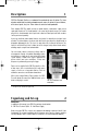
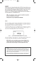
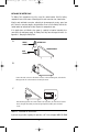
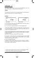
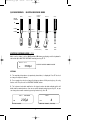
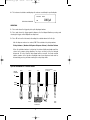
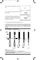
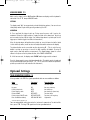
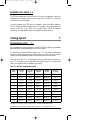
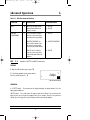
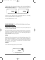
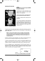
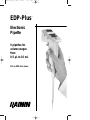
9920-055rev_g.qxd
8/9/02
11:11 AM
EDP-Plus
™
Electronic
Pipette
9 pipettes for
volume ranges
from
0.5 µL to 10 mL
250 µL EDP-Plus shown
Page 1
9920-055rev_g.qxd
8/9/02
11:11 AM
Page 2
Contents
Section 1
Section 2
Section 3
Section 4
Section 5
Section 6
Section 7
Section 8
Section 9
Section 10
Section 11
Section 12
Appendix A
Appendix B
Description ...........................................................................1
Unpacking and Set-up ...........................................................1
Basic Operation ....................................................................4
Optional Settings .................................................................12
Setting Speeds ....................................................................13
Advanced Operation ............................................................14
Proper Pipetting Technique ...................................................18
Changing Liquid Ends .........................................................19
Removing the Tip Ejector......................................................21
Care and Maintenance.........................................................21
Troubleshooting ..................................................................26
Performance Specifications ..................................................27
Charging the Battery Pack ....................................................28
Ordering Information............................................................29
FIGURES AND TABLES
Figure 1-1
Figure 2-1
Figure 2-2
Figure 3-1
Figure 3-2
Figure 8-1
Figure 8-2
Figure 8-3
FIgure 8-4
Figure 9-1
Figure 10-1
Figure 10-2
Figure 10-3
Figure 10-4
Figure A-1
Figure A-2
EDP-Plus Controls and Indicators ...........................................1
Display after Initialization Sequence ........................................2
Installing the Battery Pack ......................................................3
Holding the EDP-Plus Pipette..................................................4
Resuming Operation after Auto Shut-Off ...................................5
Volume Markings on Liquid End ...........................................19
Removing the Liquid End .....................................................19
Attaching the Liquid End ......................................................20
Display afer Initialization Sequence .......................................20
Removing the Tip Ejector......................................................21
Typical Piston Seal Assembly ...............................................22
Removing the Piston Assembly from the Liquid End ................23
2.5 mL Liquid End, Removing the Piston Seal........................23
10 mL Liquid End Assembly.................................................24
Connecting Wall Power Supply .............................................28
Rapid Charge Stand Accessory .............................................28
Table 3.1
Table 5.1
Table 6.1
Table 12.1
EDP-Plus Basic Operation......................................................4
EDP-Plus Programmable Speeds ..........................................13
EDP-Plus Advanced Functions..............................................14
EDP-Plus Specifications.......................................................27
“EDP-Plus”, “EDP”, and “EDP2” are trademarks of Rainin Instrument, LLC. ©1989-2002, Rainin Instrument, LLC. All
rights reserved. EDP-Plus Pipettes are manufactured under U.S. Patent No. 4,671,123; 4,779,467 and 4,905,526,
and under the following national patents: Taiwan, NI-23042, Australia, AU 589891, France, FR 2559904, Europe:
CH, DE, GB, IT, NL, EP 0152120 and EP 0428500, Canada, CA 1293709, Japan, JP 1807271, Germany,
DE 3588071 and DE 3586289. Prices and specifications subject to change without notice.
9920-055rev_g.qxd
8/9/02
11:11 AM
Page 3
Description
1
EDP-Plus Electronic Pipettes use a motorized linear actuator to move the piston. The linear
actuator, controlled by a miniature onboard computer, moves the piston the correct distance,
at the correct speed, every time. Piston strokes are consistent and reproducible.
Each complete EDP-Plus pipette includes a control module, a wall power supply, and a
replaceable liquid end. The control module is the same for all volume ranges; an encoder
plug tells the control module which liquid end is attached. Extra liquid ends with encoders
can be purchased separately.
A precisely machined chrome-plated stainless steel piston* is moved by an electronic linear
actuator. The piston displaces a column of air which picks up or dispenses liquid through a
disposable polypropylene tip. This tip is the only part of the instrument that touches the
liquid. A mechanical tip ejector** allows tips to be changed easily without hand contact,
avoiding sample carryover and contamination.
You enter mode, volume, and speed settings into the
microcomputer through a keyboard. Operational status
and settings are shown on an easy-to-read LCD (liquid
crystal display). Audible tones signal completion of
piston strokes and error conditions. Pickup and
dispense are performed by pressing the trigger.
Encoder Plug
Display
Power can be supplied to the EDP-Plus pipette in either
of two ways: with a cord attached to a wall power
supply, or with an rechargeable Battery Pack for
maximum convenience and freedom of movement.
With a fully-charged Battery Pack installed, the EDPPlus will operate for more than 1000 full-stroke cycles
before recharging is needed.
Keyboard
Tip Ejector Button
FIGURE 1-1
EDP-PLUS CONTROLS AND
INDICATORS
* The piston in the 10 mL liquid end is polished stainless steel, not chrome-plated.
** Except 2.5 mL and 10 mL liquid ends.
Unpacking and Set-up
2
UNPACKING
In addition to this manual, your EDP-Plus package should contain:
1. EDP-Plus Electronic Pipette 2. Wall Power Supply
Before using your EDP-Plus, inspect each component for damage sustained in transit. If you
find damage, file a claim immediately with the shipping carrier. Save the shipping container
until any damage claim is resolved and the instrument is checked and operates properly.
1
9920-055rev_g.qxd
8/9/02
11:11 AM
Page 4
WARRANTY
Complete and return the Warranty Registration Card. All EDP-Plus Electronic Pipettes carry a
one year warranty against defects in materials and workmanship. Physical and chemical
abuse are not covered. For information regarding the warranty or repair of any instrument,
please call RAININ at 800-543-4030, e-mail: [email protected], www.rainin.com
Outside the U.S.A., local warranty conditions may apply. Contact your Rainin distributor: see
www.rainin-global.com or e-mail [email protected].
NOTE: If the equipment is used in a manner not specified, the protection
provided by the equipment may be impaired.
Warranty returns are only accepted with prior authorization.
SET-UP
Connect the wall power supply to a power outlet matching the line voltage printed on the
label (105-130 VAC/50-60 Hz, or 210-260 VAC/ 50-60 Hz). Then plug the cord from the
power supply into the socket on the back of the control module.
The EDP-Plus pipette will execute its initialization routine. After about 5 seconds the
instrument will be in PIPETTE mode and the display should be as shown in Figure 2-1. If
not, refer to the Troubleshooting Guide in Section 11 of this manual.
PICKUP
KB
FIGURE 2-1
1000µl
DISPLAY AFTER INITIALIZATION SEQUENCE (EP-1000 SHOWN)
Your EDP-Plus pipette is now ready for use. If you have purchased the Battery Pack
Accessory, install it into the control module as described in the following pages.
NOTE: EDP-Plus can be used without a power cord when the Battery Pack is
installed. However, before installing the Battery Pack, it is a good idea to test
operation with the wall power supply, to see that the pipette works correctly.
WARNING:
This equipment generates and uses radio frequency energy and if not installed and used properly, i.e. in
strict accordance with the instruction manual, may cause harmful interference to radio communications.
It has been tested and found to comply with the limits for a Class A computing device pursuant to
Subpart J of Part 15 of FCC rules, which are designed to provide reasonable protection against such
interference when operated in a commercial environment.
Operation of this equipment in a residential area is likely to cause interference, in which case the user at
his own expense will be required to take whatever measures may be required to correct the interference.
2
9920-055rev_g.qxd
8/9/02
11:11 AM
Page 5
INSTALLING THE BATTERY PACK
The Battery Pack compartment is at the rear of the control module. Slide the battery
compartment cover left to remove it. Carefully pull the male connector clear, shown below .
Align the male and female connectors, noting the pin pin arrangement: one pin, space, two
pins. Fasten the connectors together, but do not force them. Insert the Battery Pack into the
control module as indicated on the label. Replace the compartment cover.
If the pipette does not initialize when power is supplied, but worked normally when
connected to the wall power supply, the Battery Pack may have discharged in transit. See
Appendix A – Charging the Battery Pack.
A
FEMALE
CONNECTOR
BATTERY PACK
CONTROL MODULE
MALE
CONNECTOR
B
Connect the male connector to the female connector on the new battery pack, and rotate the
battery pack into the control module as shown by the arrow.
C
Push the battery pack into the control module as far as possible, as shown at left. Push the
wires to the right of the battery as shown at right. Replace the battery door and slide it
closed.
FIGURE 2-2
INSTALLING THE BATTERY PACK
If you have any questions regarding this procedure, call Technical Support: 800-543-4030.
3
9920-055rev_g.qxd
8/9/02
11:11 AM
Page 6
Basic Operation
3
EDP-Plus can operate in five modes:
MODE
KEY
DESCRIPTION
P: PIPETTE
F 1
A single volume is picked up and dispensed.
M: MULTIPLE
DISPENSE
F 2
A single volume is picked up and multiple
volumes dispensed stepwise.
T: TITRATE
F 3
A single volume is picked up and partially
dispensed under trigger control.
D: DILUTE
F 4
Diluent and sample are picked up
separately and dispensed together.
MEAS:
MEASURE
F 5
A sample is picked up under trigger control
and its volume is displayed.
Table 3.1 – EDP-Plus Basic Operation
Modes are seletced in EDP-Plus by holding the F key and
a number key as shown in the table above. The keyboard
shows the name or initial of the mode. See sketch to right:
The instrument powers up in PIPETTE mode.
You can change modes when:
1. The piston is in the HOME position and KB is displayed. (If necessary, press the
FUNCTION key F and then 0 to clear the current operation and move the piston to HOME.
KB should then appear on the display.)
2. The keyboard is not locked. (Press F 9 to unlock.)
To change modes press F then the appropriate number key. For
example, to open TITRATE mode press F 3 . For MULTIPLE
DISPENSE mode, press F 2 .
The EDP-Plus pipette has been designed to be easy to use
whether you are right- or left-handed. The balance, weight,
comfortable “feel”, and light touch of EDP-Plus make it ideal for
continuous use.
Hold EDP-Plus loosely as shown in Figure 3-1. You do not need
to grip the pipette tightly during operation. Operate the trigger
with your index finger and the tip ejector button with your thumb.
Because there is no need for thumb pressure during pick up,
dispense, and blowout, operator fatigue is greatly reduced
compared to manual pipettes.
FIGURE 3-1
HOLDING EDP-PLUS
4
9920-055rev_g.qxd
8/9/02
11:11 AM
Page 7
AUTO SHUT-OFF
The EDP-Plus pipette shuts itself off automatically if none of the keys or the trigger are
pressed for three minutes. If the display is blank and the trigger does not work while power
is supplied, EDP-Plus is shut off. Press any of the top row keys or E to turn on the
instrument.
V SEQ
F
L
7
8
9
D
MEAS
MIX
4
5
6
C
P
M
T
0
1
2
3
FIGURE 3-2
S
.
Press any key in this row
or E
when EDP-Plus is shut off
E
RESUMING OPERATION AFTER AUTO SHUT-OFF
EDP-Plus remembers current operational settings when “shut-off”, and will resume
operation at the same point and with the same settings as when last used, as long as
power to the instrument has not been interrupted.
This feature is provided to extend the life of the Battery Pack accessory.
BASIC OPERATION
The examples used in this manual show the display for EP-1000 (EDP-Plus with 1000 µL
nominal volume). Your instrument will operate in the same way, but volumes shown will be
different if your pipette has a different nominal volume.
Attach a disposable tip by pressing the liquid end shaft firmly into the tip. Use water as your
sample until you are familiar with the EDP-Plus pipette.
QUICK REFERENCE:
PIPETTE MODE
Ready
Pick up
Dispense
Blowout
Ready
PISTON
POSITION
UP
HOME
DOWN
TRIGGER> > >
TRIGGER> > >
PAUSE > > >
PAUSE > > >
Holding in the
trigger delays
this step
BEEP
BEEP
5
BEEP
BEEP
9920-055rev_g.qxd
8/9/02
PIPETTE MODE
11:11 AM
Page 8
F 1
When power is supplied, EDP-Plus executes a five-second initialization sequence and
opens in PIPETTE mode. The display will show the nominal volume.
SETTINGS
Press number keys then the E (Enter) key to change the volume. The display will flash on
and off. If you make a mistake, set a new volume then press E .
OPERATION
PICKUP
KB
DISPENSE
475µl
475µl
PICKUP VOLUME
DISPENSE VOLUME
1. Press and release the trigger* to pick up the displayed volume. You will hear a “beep” at
the end of the piston stroke. See diagram at left.
2. Press and release the trigger again to dispense the liquid. See diagram at right.
The piston moves to HOME, then rapidly executes a blowout stroke. You will hear a beep at
the end of the blowout. After a one-second delay the piston returns to HOME ready for the
next pickup. This is signalled by two beeps**.
The one-second delay is to give you time to remove the tip from the dispense vessel before
the piston returns to HOME position. You can extend the delay by holding in the trigger as
the sample is dispensed.
When EDP-Plus is in any other mode, open PIPETTE mode as follows:
a. Press F 0 . This action will clear the current operation and move the piston to HOME
position. KB will show on the display, indicating the piston is HOME. (Check the keyboard
is not locked. If locked, press F 9 to unlock it.)
b. Press F 1 to open PIPETTE mode.
The display will show the nominal volume unless you have previously set a volume in
PIPETTE mode. (In all modes, any previously entered volume is remembered by EDP-Plus
as long as power is supplied continuously.)
* Holding the trigger in postpones the next step in all modes except TITRATE, MEASURE, and MIX.
** Each piston stroke is signalled by a short beep when the tone generator is turned on.
End-of-stroke beeps will not be included in the following descriptions.
6
9920-055rev_g.qxd
8/9/02
QUICK REFERENCE:
11:11 AM
Page 9
MULTIPLE DISPENSE MODE
Ready
Dispense
Multiple
Pick up
Blowout
Ready
PISTON
POSITION
UP
HOME
DOWN
REPEAT
TRIGGER> > >
TRIGGER> > >
BEEP
CLEAR > > >
BEEP (AFTER
EACH ALIQUOT)
PAUSE > > >
BEEP
BEEP
BEEP
BEEP
MULTIPLE DISPENSE MODE F 2
Make sure the piston is at the HOME position (KB shows on display) and the keyboard is
not locked. Open MULTIPLE DISPENSE mode by pressing F 2 .
PICKUP
MULTI
MULTIPLE DISPENSE NOMINAL VOLUME
1000µl
KB
SETTINGS
1. The nominal pickup volume (or previously stored value) is displayed. Press E to check
or change the dispense volume.
2. Press number keys to set or change the dispense volume. While pressing keys, the entry
flashes until E is pressed. See DISPENSE VOLUME, below
3. The instrument calculates and flashes the largest number of whole aliquots which will
divide into the nominal volume. You can accept this aliquot number by pressing E , or you
can change to a smaller number by pressing number keys, then E .
MULTI
KB
DISPENSE
MULTI
235µl
KB
DISPENSE VOLUME
4
NUMBER OF ALIQUOTS (FLASHING)
7
9920-055rev_g.qxd
8/9/02
11:11 AM
Page 10
4. The instrument calculates and displays the volume needed to pick up all aliquots.
PICKUP
940µl
KB
TOTAL PICKUP VOLUME
MULTI
OPERATION
1. Press and release the trigger to pick up the displayed volume.
2. Press and release the trigger again to dispense the first aliquot. Continue pressing and
releasing the trigger until all aliquots are dispensed.
3. Press 0 to clear the instrument, discarding the residual volume left in the tip.
After the dispense volume isn entered, EDP-Plus calculates the pickup volume:
Pickup Volume = (Number of Aliquots x Dispense Volume) + Residual Volume
When the calculated volume is picked up, the piston slightly overshoots and then
returns to its proper pickup position, to ensure accuracy of the first aliquot
dispensed. To ensure that the last aliquot will be accurate, the fixed residual
volume remains in the tip after all aliquots have been dispensed and must be
discarded by pressing 0 before making the next pickup stroke.
QUICK REFERENCE: TITRATE MODE
Ready
Pick up
Titrate
Discard remainder
and Blowout
Ready
PISTON
POSITION
UP
HOME
DOWN
TAP or HOLD
TRIGGER> > >
TRIGGER> > >
F 0 to
CLEAR > > >
BEEP
PAUSE > > >
BEEP
READ VOLUME
DISPENSED
8
BEEP
BEEP
9920-055rev_g.qxd
8/9/02
11:11 AM
Page 11
TITRATE MODE F 3
Make sure the piston is at the HOME position (KB shows on display) and the keyboard is
not locked.
TITRATE
PICKUP
Open TITRATE mode by pressing F 3 .
KB
1000µl
TITRATE NOMINAL VOLUME
SETTINGS
1. The display shows the nominal pickup volume.
To change the pickup volume, enter a new initial
pickup volume with the number keys and press E .
TITRATE
PICKUP
KB
560µl
INITIAL PICKUP VOLUME SET
2. To set an initial dispense volume, press number
keys then press E . (To set an initial dispense
volume without changing the initial pickup volume,
press E first. Enter the volume with number keys.
Then press E again.)
TITRATE
KB
DISPENSE
150µl
INITIAL DISPENSE VOLUME SET
OPERATION
1. Press and release the trigger to pick up the initial volume.
2. To begin titration, press and hold the trigger to dispense liquid first slowly, then at an
increasing rate. The longer the trigger is held, the faster the liquid is dispensed. Release and
hold in the trigger again to restart dispensing at the slowest rate. To dispense one increment
at a time, tap the trigger.
3. When the desired endpoint is reached, read and record the dispensed volume from the
display. Then clear the instrument by pressing F 0 . This will discard the remainder in the
tip and return EDP-Plus to its starting position.
If the entire volume is titrated, press the 0 key when the beep sounds and the display reads
“CLEAR”. This action will execute the blowout stroke and empty the residual volume from
the tip.
In TITRATE mode, a small residual volume is left in the tip after the entire volume has been
titrated. The residual volume ensures that the volume titrated is accurate. The residual
volume is not part of the titrated volume and must be discarded by pressing F 0 .
9
9920-055rev_g.qxd
8/9/02
QUICK REFERENCE:
11:11 AM
DILUTE MODE
Pick up
Diluent V1
Ready
Page 12
Pick up
Air
Pick up
Sample V2
Blowout
Dispense
Ready
PISTON
POSITION
UP
HOME
DOWN
TRIGGER> > >
TRIGGER> > >
TRIGGER> > >
TRIGGER> > >
PAUSE > > >
PAUSE > > >
Holding
trigger
delays this
step
DILUENT
AIR GAP
SAMPLE
BEEP
BEEP
BEEP
BEEP
BEEP
BEEP
BEEP
BEEP
DILUTE MODE F 4
Make sure the piston is at the HOME position (KB shows on display) and the keyboard is
not locked. Press F 4 to open DILUTE mode. The display will show the default diluent
volume, which is 90% of nominal volume. (The default sample volume is 10% of nominal
volume, for 10:1 dilution.)
SETTINGS
1. Set the diluent volume (V1) by pressing number keys then E
.
DILUTE
DILUENT VOLUME
KB
500µl
V1
2. Set the sample volume (V2) in the same way.
DILUTE
SAMPLE VOLUME
KB
100µl
V2
OPERATION
1. Press and release the trigger to pick up the diluent.
DILUTE
PICKUP
PICK UP DILUENT VOLUME
10
KB
500µl
V1
9920-055rev_g.qxd
8/9/02
11:11 AM
Page 13
2. Press and release the trigger to pick up an air
gap*.
Air
DILUTE
PICKUP
3. Press and release the trigger a third time to pick
up the sample.
100µl
V2
DILUTE
4. A three-part tone sounds, indicating that diluent
and sample are separated by the air gap, ready to
be dispensed. Press and release the trigger to
dispense diluent and sample.
DISPENSE
600µl
DISPENSE DILUENT AND SAMPLE TOGETHER
5. The display shows the diluent volume, ready for the next cycle.
* When using DILUTE mode with the 10mL liquid end, the air gap will probably rise through the diluent and allow
diluent and sample to mix in the sample reservoir. To avoid this, you can use VOLUME SEQUENCING in DILUTE
mode. Then set a smaller air gap, or no gap, as desired. See Section 6 — Advanced Operation: VOLUME
SEQUENCING.
QUICK REFERENCE:
MEASURE MODE
Ready
Discard
remainder
Pick up
Blowout
Ready
PISTON
POSITION
UP
HOME
DOWN
TAP or HOLD
TRIGGER> > >
F 0 to
CLEAR > > >
PAUSE > > >
PAUSE > > >
Holding
trigger
delays this
step
READ VOLUME
MEASURED
BEEP
BEEP
BEEP
NOTES :
1. An initial pickup volume can be set.
2. Piston direction can be changed by pressing 0 , even while the trigger is pressed.
3. At full stroke (or at zero) the trigger must be released. Then either press F 0 to clear the pipette, or press
the trigger again to reverse piston direction.
11
9920-055rev_g.qxd
8/9/02
11:11 AM
Page 14
MEASURE MODE F 5
Make sure the piston is at the HOME position (KB shows on display) and the keyboard is
not locked. Press F 5 to open MEASURE mode.
SETTINGS
The display reads “0µl” (or any previously entered initial pickup volume). You can enter an
initial pickup volume if you wish by pressing number keys then E .
OPERATION
1. Press and hold the trigger to pick up. Pickup speed increases until it reaches the
maximum. Release the trigger and press it again to restart at the slowest rate. To pick up
one increment at a time, tap the trigger. (Any initial pickup volume is picked up at the first
trigger press. Hold the trigger in to continue measurement.)
When the desired volume of liquid has been picked up, ensure the lower level of the liquid
is flush with the tip orifice (no air has been included) and read the volume on the display.
The piston direction can be reversed at any time by pressing 0 . (This is useful if an air
bubble is picked up; pressing 0 reverses the flow, expelling the bubble. Pressing 0
again reverses flow and continues measurement.) The display always shows the current
volume in the tip as well as the piston direction, either PICKUP or DISPENSE.
2. At full- or zero-scale, the display reads “CLEAR” and the trigger must be released.
Press the trigger again to reverse direction automatically. (The pipette may be cleared and
the tip contents dispensed by pressing F 0 ; this is useful if the volume of liquid to be
picked up exceeds the full-scale volume of the instrument.)
Optional Settings
4
TONE GENERATOR CONTROL F 8
A tone generator in the EDP-Plus signals operational status or error conditions as follows:
Status
Tone sound
Tone description
Initialization
Key press
End of pickup stroke
End of dispense stroke
Piston at HOME
End of pickup in DILUTE mode
Error condition/Low battery*
BEEP-BEEP
BIP
BEEP
BEEP
BEEP-BEEP
BEEP-BEEP-BEEP
DEE-DAH-DEE-DAH
Two short beeps
One very short beep
One short beep
One short beep (lower tone)
Two short beeps
Two short, one long beep
High warble
* Works even when tone generator is OFF
Tones are automatically switched on when the instrument is powered up. To switch off the
tones, press F 8 . Pressing F 8 again turns the tone generator back on.
12
9920-055rev_g.qxd
8/9/02
11:11 AM
Page 15
KEYBOARD LOCK CONTROL F 9
The EDP-Plus keyboard can be locked if desired. This feature is for protection. Locking the
keyboard prevents unwanted volume or mode changes when the EDP-Plus is used for the
same task over an extended period.
To lock the keyboard, press F 9 when the keyboard is active (when KB is displayed).
Press F 9 again to unlock the keyboard. When the keyboard is locked, all keystrokes are
ignored excep F 0 (clear), F 8 (tone generator control), and F 9 (keyboard
lock/unlock). The trigger operates whether the keyboard is locked or unlocked.
Setting Speed
5
PROGRAMMABLE SPEED
F •
You can program the pickup and dispense speed of the EDP-Plus pipette to accommodate
almost any liquid, including moderately dense or viscous liquids.
The default speed setting for EDP-Plus pipettes is 8*. This fast setting is optimized for
liquids with similar physical properties to water. However, you may wish to set a higher
speed for even faster operation or a slower speed for more dense or viscous liquids.
To reset the speed, press F • (decimal point) then press a number between 0 and 9, then
press E . The display reverts to show volume after speed has been set. The table below
shows cycle component times for available speed settings.
Table 5.1 – EDP-Plus Programmable Speeds
Speed
Setting
Full-Scale
Pickup
Full-Scale
Dispense
Delay before
Blowout
Blowout
duration
Dwell Time
(constant)
9
1.3 sec.
1.3 sec.
0.0 sec.
0.13 sec.
1.0 sec.
8
1.3 sec.
1.3 sec.
0.5 sec.
0.13 sec.
1.0 sec.
7
1.3 sec.
1.3 sec.
1.0 sec.
0.13 sec.
1.0 sec.
6
2.2 sec.
2.2 sec.
0.5 sec.
0.22 sec.
1.0 sec.
5
2.2 sec.
2.2 sec.
1.0 sec.
0.22 sec.
1.0 sec.
4
2.2 sec.
2.2 sec.
1.5 sec.
0.22 sec.
1.0 sec.
3
2.2 sec.
2.2 sec.
2.0 sec.
0.22 sec.
1.0 sec.
2
4.4 sec.
4.4 sec.
0.5 sec.
0.44 sec.
1.0 sec.
1
4.4 sec.
4.4 sec.
1.0 sec.
0.44 sec.
1.0 sec.
0
4.4 sec.
4.4 sec.
2.0 sec.
0.44 sec.
1.0 sec.
This table does not apply to trigger-controlled actions in TITRATE and MEASURE modes.
* Default speed setting for EDP-Plus 10ML and M8 models is 5. Speed range is from 0 – 6.
13
9920-055rev_g.qxd
8/9/02
11:11 AM
Page 16
Advanced Operation
6
Table 6.1 – EDP-Plus Advanced Functions
FUNCTION
KEY
DESCRIPTION
APPLICABLE MODE
MIX
F 6
Mixes by repeated up-anddown piston motion while
trigger is held in
P – PIPETTE
D – DILUTE
VOLUME
SEQUENCING
F 7
PIPETTE: up to 12 distinct
volumes can be picked up
and dispensed sequentially.
P – PIPETTE
MULTIPLE DISPENSE: up
to 12 distinct volumes can
be dispensed sequentially
from a single pickup volume.
M – MULTIPLE DISPENSE
DILUTE: up to 12 distinct
volumes can be picked up
sequentially and dispensed
together.
D – DILUTE
MIX
F 6
Available in PIPETTE and DILUTE modes only.
SETTINGS
1. Open the MIX function by pressing F 6 .
2. The display prompts you for a mix volume*.
Enter this volume and press E .
KB
200µl
V
MIX
MIX VOLUME ENTERED
OPERATION
1. (PIPETTE mode) Press and release the trigger to aspirate the pickup volume. Press the
trigger again to dispense.
(DILUTE mode) Press and release the trigger to pick up the diluent. Press and release the
trigger to pick up an air gap, and again to pick up the sample. When the three-part tone
sounds, press the trigger once more to dispense diluent and sample together.
* The mix volume may be larger than the pickup or diluent/sample volumes.
14
9920-055rev_g.qxd
8/9/02
11:11 AM
Page 17
2. Hold the trigger (either during or after the dispense stroke) to start mixing. Mixing will
continue as long as the trigger is held in. The display alternates between PICKUP and
DISPENSE while mixing is in progress.
DISPENSE
PICKUP
200µl
V
200µl
MIX
V
MIX
MIXING IN PROGRESS; MIX VOLUME ALTERNATELY PICKED UP AND DISPENSED
3. Release the trigger. Mixing stops and a normal blowout stroke occurs. The display
shows the pickup or diluent volume, ready for another cycle.
4. To close the MIX function press F 6 .
VOLUME SEQUENCING F 7 in PIPETTE, MULTIPLE DISPENSE, and DILUTE modes.
VOLUME SQUENCING: PIPETTE MODE
In PIPETTE mode, up to twelve distinct volumes can be picked up and dispensed
sequentially with VOLUME SEQUENCING.
When using this function, you are not restricted to the fixed sequence: by pressing the
F 0 keys you can go back and repeat the previous volume, or by pressing E you can
skip over the next volume. The sequencing cycle can be started at any point. Open the
VOLUME SEQUENCING function by pressing F 7 .
SETTINGS
Display flashes “0µl” (or the volume last set). Set the first pickup/ dispense volume (V1)by
pressing number keys followed by E . Continue setting sequential pickup/dispense
volumes. Press 0 E to end the sequence. If you enter all twelve volumes, you do not
have to press 0 to end the sequence. Sequential volumes are numbered as follows:
V1–9, then VA (10), Vb (11), & VC (12).
OPERATION
1. Press and release the trigger to pick up the current volume.
PICKUP
KB
SEQ
100µl
FIRST VOLUME PICKED UP
15
V1
9920-055rev_g.qxd
8/9/02
11:11 AM
Page 18
2. Press and release the trigger to dispense the current volume.
DISPENSE
100µl
SEQ
V1
1ST VOLUME DISPENSED
3. Press and release the trigger to pick up the next sequential volume.
PICKUP
KB
SEQ
150µl
V2
2ND VOLUME PICKED UP
4. Press and release the trigger to dispense the next sequential volume. Continue in this
way until all volumes are picked up and dispensed.
5. After the last volume in the sequence is dispensed, the first volume is displayed again,
ready for pickup.
6. To close the VOLUME SEQUENCING function, press F 7 .
VOLUME SEQUENCING: MULTIPLE DISPENSE MODE
In MULTIPLE DISPENSE mode with VOLUME SEQUENCING, up to 12 distinct volumes can be
dispensed sequentially from one pickup volume. Open the VOLUME SEQUENCING feature by
pressing F 7 .
SETTINGS
1. The display flashes “0µl” (or the volume last set). Enter the first volume (V1) with the
number keys and press E .
2. The display flashes “0µl” again, prompting you for the next volume. Enter the second
volume (V2) and continue in the same way for each entry, finishing each entry with
E and the last entry with 0 E . Sequential volumes are numbered as follows: V1–9, then
VA (10), Vb (11), & VC (12).
3. The EDP-Plus pipette calculates and displays the number of cycles, or the largest
number of times the sum of the volumes will divide into the nominal volume of the
instrument. Accept the number of cycles by pressing E , or set a smaller number and press
E . (Setting a larger number will sound an error alarm.)
OPERATION
1. The display will show the volume to be picked up; press and release the trigger to pick
up that volume.
16
9920-055rev_g.qxd
8/9/02
11:11 AM
Page 19
2. The next trigger press will dispense the first sequential volume. The next trigger press will
dispense the second sequential volume, and so on.
3. After all sequential volumes in the first cycle have been dispensed, press the trigger to
begin the second cycle. Continue until all cycles are complete.
4. The display will read “CLEAR” after the last dispense volume in the last cycle. Press
0 to clear the instrument.
5. To close the VOLUME SEQUENCING function, press F 7 .
VOLUME SEQUENCING: DILUTE MODE
In DILUTE mode with VOLUME SEQUENCING, up to twelve distinct volumes can be picked
up sequentially and dispensed together. Open VOLUME SEQUENCING by pressing F 7 .
SETTINGS
1. Display flashes “0µl” (or volume last set). Press number keys then E to set the first
sequential volume (V1).
2. Display flashes “0µl” (or volume last set). Press number keys followed by E to set the
next volume (V2). Sequential volumes are numbered as follows: V1–9, then VA(10),
Vb (11), & VC (12).
3. Continue in this way until all volumes are set. Press 0 E to end the sequence.
OPERATION
1. The display shows the first pickup volume. Press and release the trigger to pick up the
first volume (V1).
2. Press and release the trigger again to pick up the next volume (V2). Air gaps are not
automatically added when VOLUME SEQUENCING. If you wish, air gaps can be set as
volume entries.*
3. Continue in this way until all volumes are picked up.
4. A three-part tone sounds. Press the trigger to dispense the total volume all at once.
5. The display shows the first pickup volume again. Press and release the trigger to pick up
volume V1 and restart the cycle.
6. To close the VOLUME SEQUENCING function, press F 7 .
* This is a good way to avoid the potential problem when using DILUTE mode with the 10mL liquid end — that of the
air gap rising through the diluent, allowing diluent and sample to mix in the sample reservoir. You can set a smaller
air gap which will stay in place between the diluent and sample. See Section 3 — Basic Operation, DILUTE mode.
17
9920-055rev_g.qxd
8/9/02
11:11 AM
Page 20
Proper Pipetting Technique
7
Use RAININ tips
EDP-Plus pipettes are designed for use with RAININ-manufactured disposable tips. Specified
performance of EDP-Plus pipettes is guaranteed only when RAININ disposable tips are used
as recommended in Section 8. RAININ cannot accept responsibility for damage to EDP-Plus
pipettes or for poor performance resulting from the use of other than RAININ disposable tips.
RAININ disposable tips are molded from premium-grade virgin polypropylene plastic.
Molds are inspected and maintained frequently to assure high-quality tip production.
Samples from each lot of tips are inspected microscopically to assure that every lot meets
these high standards. To order Tips for EDP-Plus Pipettes, please refer to the RAININ
Pipetting Solutions Catalog or the current RAININ Product Update. Call 800-543-4030 for
a free copy of these publications. You can also view or download a PDF version online:
http://www.rainin.com/lit_prodlit.asp
Pipetting techniques
EDP-Plus pipettes are designed to deliver accurate and precise measurements under the
following conditions:
1. The liquid pipetted is water or liquid with density, viscosity, and vapor pressure similar to
water. The temperature of the room, the EDP-Plus, and the liquid, are all in the range
21.5°C ± 1°C. The EDP-Plus pipette is kept vertical while pipetting or within 20° of vertical.
2. The end of the disposable tip is immersed beneath the sample surface as follows:
2 to 3 mm – volumes up to 100 µL.
2 to 4 mm – volumes from 100 µL to 1000 µL.
3 to 6 mm – volumes over 1000 µL.
3. There is no significant adherence of liquid to the surfaces of the tip. (Each tip should be
rinsed once before pipetting to assure the best precision).
4. When dispensing, the tip is touched to the sidewall of the receiving vessel. At the end of
each dispense cycle, the tip is moved along the wall to remove any excess sample from the
outside of the tip. A consistent rhythm is maintained from sample to sample when pipetting.
Viscous liquids, such as serum or plasma, can be measured accurately with a slow speed.
See Table 5.1 – Programmable Speeds. You can further improve accuracy with viscous
solutions by using MULTIPLE DISPENSE mode with the number of aliquots set to 1 and
using a slow speed. This method simulates “reverse-mode” pipetting in manual pipettes. In
MULTIPLE DISPENSE mode, the volume picked up includes an extra residual volume and
the volume of the dispensed aliquot is accurate.
You can measure warm or cold liquids with good precision by using a consistent pipetting
rhythm. A consistent rhythm will help minimize any differences in heating or cooling effects
within the pipette. Use a new disposable tip each time for best accuracy and precision when
measuring samples with temperatures greatly different from ambient, and do not pre-rinse.
As with any air-displacement pipette, best results will be obtained if there is no delay
between picking up the sample and dispensing it.
18
9920-055rev_g.qxd
8/9/02
11:11 AM
Page 21
Changing Liquid Ends
8
EDP-Plus liquid ends are interchangeable. The liquid
end nominal volume is marked in two places, shown
in Figure 9-1. The encoder plug is marked on its top
surface. The liquid end can be mounted very quickly on
the EDP-Plus control module as described below.
Before removing the liquid end, bring the piston to
HOME by pressing F 0 . The letters KB should
appear on the display. If the keyboard is locked, unlock
it (press F 9 ).
FIGURE 8-1
VOLUME MARKINGS ON LIQUID END
TO REMOVE THE LIQUID END
1. Referring to Figure 8-2a , loosen the shaft retaining nut by rotating it counter-clockwise.
2. When the shaft retaining nut is free of the threads, pull the liquid end away from the
control module. (Figure 8-2b.)
3. Remove the encoder plug from the control module (Figure 8-2c) and store it with its
matching liquid end. Liquid measurements made with the EDP-Plus will be accurate and
precise ONLY when the correct liquid end/encoder plug combination is used.
NOTE: Before storage, disassemble the liquid end and inspect for salts or
residues. Clean the liquid end and keep it with its encoder plug. Do not touch
the underside of the plug; skin oils can contaminate it, causing poor electrical
contact and performance. The plug can be cleaned with isopropanol.
A
FIGURE 8-2
B
C
REMOVING THE LIQUID END
19
9920-055rev_g.qxd
8/9/02
11:11 AM
Page 22
REINSTALLING THE LIQUID END
CAUTION:
Always attach the replacement liquid end BEFORE
inserting the encoder plug.
1. Refer to Figure 8-3. Hold the shaft retaining nut and
support the liquid end upright with its end on a smooth
soft surface such as a paper towel.
Actuator
Seat
Keyway
Tip
Ejector
Pin
2. Bring the liquid end and the control module together
with the control module directly above the liquid end.
Actuator
Pin
3. Engage the actuator pin with the actuator seat on the
piston retainer.
Piston
Retainer
FIGURE 8-3
4. Push the liquid end toward the control module body
and rotate the liquid end so the tip ejector pin on the
control module fits through the matching hole on the
liquid end shaft. With the tip ejector pin in the proper
position, the control module key will be aligned with the
keyway on the shaft.
ATTACHING THE LIQUID END
5. Hold the liquid end and control module together and thread the shaft retaining nut onto the
control module. Ensure the threads do not cross, and hand-tighten the shaft retaining nut
onto the control module.
NOTE: 2.5 mL and 10 mL models do not use tip ejectors. For these models,
engage the actuator pin into the piston retainer and thread the liquid end onto
the control module. Store the shaft retaining nut and tip ejector spring for use
with other liquid ends.
6. Take the replacement encoder plug. Make sure the labels on the plug and liquid end
match. Also check the markings on the liquid end (these are shown in Figure 9-1).
7. Align the encoder plug with its slot in the head of the control module (avoid touching the
bottom of the plug) and insert the plug squarely. If power is supplied to the EDP-Plus and the
keyboard is unlocked, the initialization sequence begins when the encoder plug is in place.
8. After the initialization sequence, look at the display. The EDP-Plus pipette should be in the
pipette mode with the display reading PICKUP. The nominal volume of the liquid end is also
displayed, as shown in Figure 9-4. (If your display does not show the proper nominal
volume, check that the correct encoder plug is installed.)
PICKUP
KB
1000µl
FIGURE 8-4
DISPLAY AFTER INITIALIZATION SEQUENCE (EP-1000 SHOWN)
20
9920-055rev_g.qxd
8/9/02
11:11 AM
Page 23
Removing the Tip Ejector
9
The EDP-Plus pipette liquid end (except 2.5 mL and 10mL) has a built-in tip ejector,
operated by pressing the thumb button. The tip ejector is a hollow spring-loaded moveable
shaft surrounding the liquid end and extending up through the shaft retaining nut.
The EDP-Plus pipette is normally operated with the tip ejector in place, allowing disposable
tips to be ejected without hand contact. However, when using deep, narrow reservoirs you
may wish to operate the pipette without the tip ejector in place.
Refer to Figure 9-1 and remove the tip ejector as follows:
1. Loosen the shaft retaining nut (counter-clockwise).
2. Pull the liquid end (with tip ejector) from the control module.
3. Slip the shaft retaining nut from the tip ejector.
4. Remove the tip ejector from the liquid end, as shown in
Figure 10-1, and set it aside until you need it again.
5. Slide the shaft retaining nut over the liquid end.
6. Thread the shaft retaining nut carefully onto the control
module threads, and tighten the liquid end in place. Do not
overtighten.
FIGURE 9-1
REMOVING THE TIP EJECTOR
CAUTION: Do not press the trigger during this operation.
Care and Maintenance
10
EDP-Plus pipettes are designed to need very little maintenance and should give years of
trouble-free service if treated with proper care and the operating recommendations in Section
8 are followed. Also see: RAININ Publication AB-15, Procedure for Evaluating Accuracy and
Precision of RAININ Pipettes, available online at http://www.rainin.com/pdf/ab15.pdf
The following rules should be strictly observed to keep the mechanism dry and clean.
1. Never allow liquid to enter the shaft where it can contact the piston or seal.
2. Never pick up liquid without a disposable tip attached.
3. Never invert EDP-Plus or lay it on its side with liquid in the tip. Always hold it upright.
4. Never use solvents to clean EDP-Plus. Instead, use a lint-free wipe dampened with water
to clean the instrument. Keep the keyboard and encoder plug dry.
21
9920-055rev_g.qxd
8/9/02
11:11 AM
Page 24
SEALS
Periodically each liquid end (except the 10 µL) should be tested to ensure proper sealing,
as follows:
1. Set the nominal volume and attach a disposable tip.
2. Pick up the full volume of water.
3. Hold the instrument upright and observe the tip for 30 to 45 seconds.
There should be no leaks from the tip or droplet formation at the tip orifice. If leakage does
occur, the seal between the tip and the shaft may not be airtight.
DISPOSABLE TIP SEAL
Use only RAININ disposable pipette tips as recommended in Section 5. These tips mate
exactly with the EDP-Plus liquid end shaft to form airtight seals.
PISTON SEAL
The seal between the piston and the inside surface of the shaft is formed by a PTFE ring and
a fluoroelastomer O-ring (except the 10 mL liquid end). The PTFE ring extends through the
O-ring, and only the PTFE ring makes contact with the piston. This is shown in Figure 10-1.
(The 10 mL piston seal assembly is shown later in this section.)
The O-ring compresses the PTFE ring against the piston to maintain a proper seal even after
moderate seal wear, and also forms a stationary seal between the PTFE ring and the shaft.
Periodically you should dismantle the liquid end for
inspection and cleaning, as follows:
1. Remove the liquid end from the control module.
Do not remove the encoder plug for this procedure.
2. Inside the liquid end, press the spring-loaded
piston retainer and rotate it slightly counterclockwise to release the retainer catch.
3. Pull the piston assembly out of the liquid end
(Fig.10-2). The seal should stay attached to the
piston. If it remains in the liquid end, invert the
liquid end and gently tap it on the bench until the
seal drops out.
FIGURE 10-1
PISTON SEAL ASSEMBLY
4. Inspect the piston, seal, bushing, and inside of the shaft for any dirt and particulate
contamination. There is no need to dismantle the piston assembly any further.
22
9920-055rev_g.qxd
8/9/02
11:11 AM
Page 25
5. Remove any contamination by soaking and
rinsing the piston assembly with distilled water or
alcohol. The piston surface should have a highgloss finish. If the finish is dull, scratched, or pitted,
the seal may wear very rapidly, and the complete
piston assembly should be replaced.
Piston
Assembly
6. Blow the assembly dry with clean dry
compressed nitrogen, or dry it with a very soft lintfree wipe. To avoid scoring the piston, do not use
rough material such as a paper towel.
CAUTION: Never apply grease to the
pipette seal or piston (except 10 mL).
Any grease or lubricant may alter the
effective diameter of the piston and cause
errors in liquid measurement.
Liquid End
FIGURE 10-2
REMOVING THE PISTON ASSEMBLY
FROM THE LIQUID END
REASSEMBLY
1. Make sure the PTFE seal and O-ring are properly positioned on the piston, as shown in
Figure 10-1.
2. Place the piston assembly into the liquid end, and compress the piston retainer against
the piston spring. Rotate the retainer slightly clockwise to engage the retainer catch.
3. Replace the liquid end on the control module, attach a disposable tip, and test for proper
sealing as described in the first part of this chapter.
2.5 mL LIQUID END
The 2.5 mL EDP-Plus piston assembly threads into
the shaft and is removed and replaced with a seal
wrench (Cat. No. 6100-231).
Piston
Assembly
1. Remove the liquid end from the control module.
2. Place the wrench in the slots in the piston
assembly. Turn the wrench counter-clockwise to
remove the piston assembly, as shown in Figure
10-3.
Seal
Wrench
3. Clean or replace the seal as described earlier.
4. Reinstall the piston assembly by first inverting
the shaft and threading the piston assembly into the
shaft. Tighten firmly with the wrench. Do not overtighten.
23
FIGURE 10-3
2.5 mL LIQUID END; REMOVING
PISTON SEAL
9920-055rev_g.qxd
8/9/02
11:11 AM
Page 26
5. Test operation by pushing and releasing the piston. If the piston movement is not free or
the piston does not return easily to its rest position, the O-ring and seal are probably not
seated correctly. In this case, reinstall the piston assembly.
6. Replace the liquid end on the control module.
10 mL LIQUID END
The piston seal is formed by a nitrile rubber O-ring
and fluorinated grease. Refer to Figure 10-4 and
proceed as follows:
Upper
Shaft
Body
Piston
Assembly
1. Remove the liquid end from the control module.
2. Remove the upper portion of the liquid end.
Work the spring retainer beyond the threads of the
shaft. Carefully remove the piston assem-bly,
spring, guide bushing, and O-ring. Discard the worn
O-ring.
3. Remove all traces of used grease from the shaft
interior, guide bushing, and piston assembly with a
lint-free wipe. (DO NOT USE SOLVENTS.)
4. Smear a light coat of fresh fluo-rinated grease
uniformly around the piston, ensuring that no dirt is
present. Smear a light coat of grease on the new Oring and guide bushing.
5. Place the O-ring, then the guide bushing (small
end of the bushing down) on the shelf inside the
shaft body. Place the spring on top of the guide
bushing.
Seal
Spring
Guide
Bushing
O-Ring
Lower
Shaft
Body
FIGURE 10-4
10 mL LIQUID END ASSEMBLY
6. Wipe any foreign particles from the front surface of the cone. Carefully insert the piston
into the shaft body and snap the spring retainer down beyond the shaft threads.
CAUTION: BE CAREFUL NOT TO SCRATCH THE PISTON.
7. Replace the upper body of the liquid end, taking care not to cross the thread or
overtighten.
24
9920-055rev_g.qxd
8/9/02
11:11 AM
Page 27
Troubleshooting
11
Symptom
Possible Cause
Suggested Remedy*
Inaccurate liquid
measurement or leaks
Bad seal between disposable tip
and liquid end
Use RAININ disposable tips
Damaged shaft end
Replace shaft.
Inadequate seal on piston
assembly
Check, clean, or replace
piston seal as outlined
in Section 9.
“Lob” on display,
warbling alarm
Insufficient charge in Battery Pack
Recharge Battery
Pack; see Appendix B.
Blank display, no alarm
EDP-Plus is shut off
Press any top row key
or E to turn on instrument.
Depleted Battery Pack
Recharge Battery
Pack; see Appendix B.
Wall power supply disconnected
(not using Battery Pack)
Reconnect cord to
EDP-Plus pipette.
Illegal volume entered
(will not be accepted)
Enter legal volume.
Display reads “Err”,
warbling alarm
Keyboard will not accept
Keyboard locked
entries, “KB locked” on LCD
Unlock keyboard by
pressing F 9.
* If the suggested remedy does not correct the problem, contact RAININ 800-543-4030.
If anything confusing happens during operation of the EDP-Plus pipette, it can sometimes
be remedied by pressing F 0 (unless the display is flashing, indicating an entry must be
completed). Pressing F 0 returns the piston to HOME and activates the keyboard.
You can also reset the instrument by removing power, or removing and replacing the
encoder plug. (The keyboard MUST be unlocked if you remove the encoder plug.) The
pipette will restart and reinitialize. It will be in PIPETTE mode at its nominal volume after this
sequence. This remedy should be used only as a last resort, since all stored information will
be lost from the micro-computer and will need to be re-entered.
RAININ maintains service departments to correct any electro-mechanical problems with the
EDP-Plus pipette, or problems resulting from physical or chemical damage. In the U.S.A.
please contact Technical Service at 800-543-4030 for more information and assistance.
Outside the U.S.A. contact the RAININ distributor for your country. If you do not know the
address, call International Customer Service at 001-510-564-1614, or send e-mail to
[email protected].
RAININ distributors are also listed by country on the web: www.rainin-global.com/list.html
26
9920-055rev_g.qxd
8/9/02
11:11 AM
Page 28
Performance Specifications
12
These manufacturer’s specifications should be used as guidelines when establishing your
own performance specification in accordance with ISO 8655.
Table 12.1 – Specifications
EDP-Plus
Model
10 µL
25 µL
100 µL
250 µL
1000 µL
2500 µL
10ML
VOLUME
SET µL
1
INCREMENT
µL
PRECISION
%
µL (≤)
2.5
0.025
1.2
0.012
5
1.5
0.075
0.6
0.03
10
1.0
0.1
0.4
0.04
2.50
0.01
ACCURACY
%
µL (±)
6.0
0.15
2.0
0.05
12.5
1.2
0.15
0.4
0.05
25
1.0
0.25
0.3
0.075
10
0.05
3.0
0.3
1.0
0.1
50
0.8
0.4
0.2
0.1
100
0.8
0.8
0.2
0.2
2.0
0.5
0.6
0.15
125
0.8
1.0
0.15
0.19
250
0.8
2.0
0.15
0.38
3.0
3.0
0.6
0.6
25
100
0.1
0.5
1.0
500
0.8
4.0
0.13
0.65
1000
0.8
8.0
0.13
1.3
3.2
8.0
0.8
2.0
1250
0.8
10.0
0.16
2.0
2500
0.8
20.0
0.12
3.0
5.0
50.0
0.6
6.0
5 mL
1.0
50.0
0.2
10.0
10 mL
0.8
80.0
0.16
16.0
250
1 mL
5.0
10
Specifications are subject to change without notice, and apply to PIPETTE mode operation.
27
9920-055rev_g.qxd
8/9/02
11:11 AM
Page 29
Recharging the Battery Pack
A
Power is supplied to the EDP-Plus by either a wall power supply cord, or with an accessory
Battery Pack. A fully-charged Battery Pack will allow you to make more than 1000 fullstroke cycles before charging is needed. If the Battery Pack discharges during operation, the
EDP-Plus will sound a warning and the message “Lob” will be displayed. If this occurs,
connect the EDP-Plus to a charger immediately after the current pipetting cycle. If you
connect to the wall power supply, you can continue operation without interruption.
The Battery Pack can only be charged when installed in EDP-Plus, in either of two ways:
WALL POWER SUPPLY
Connect the wall power supply cord to the connector on the back of the
control module. Connect the power supply to an AC power source with
the correct line voltage as specified on the power supply (105-130
Volts AC/50-60 Hz, or 210-260 Volts AC/50-60 Hz). The wall power
supply can recharge a completely discharged Battery Pack in about 14
hours.
FIGURE A-1
CONNECTING
WALL POWER
SUPPLY
RAPID CHARGE STAND
Connect the Rapid Charge Stand to a suitable AC power source with
the correct voltage (see paragraph above). Place EDP-Plus on the
stand so that the four contact pins on fit into the contact slots on the
stand. The display reads “FC” (Fast Charge): functions are inoperative
until EDP-Plus is removed from the stand. The Rapid Charge Stand can
recharge a Battery Pack in about 90 minutes. Current is metered
precisely, and the Battery Pack temperature continually monitored via a
built-in sensor probe. When the Battery Pack is fully charged, the red
charge indicator light on the Rapid Charge Stand goes out.
FIGURE A-2
RAPID CHARGE
STAND
For extended storage of the EDP-Plus, the Battery Pack should be fully
charged and removed from the instrument.
NOTE:
If you use a Rapid Charge Stand to rest the instrument, keep the Rapid Charge Stand
unplugged until you need to recharge the batteries. (Recharging takes about 1-1/2 hours
with the Rapid Charge Stand.)
28
9920-055rev_g.qxd
8/9/02
11:11 AM
Page 30
Ordering Information
B
EDP-Plus Pipettes, parts and accessories can be ordered online 24/7 at www.rainin.com,
or by phone, mail, or fax from:
Rainin Instrument, LLC.
Rainin Road • Box 4026, Woburn, MA 01888-4026
800-4-RAININ (800-472-4646)
FAX: 781-938-1152
e-mail: [email protected]
7500 Edgewater Drive, Box 2160, oakland, CA 94621-0060
FAX 510-564-1617
RAININ Japan: 4-1-11, Hongo, Bunkyo-Ku, Tokyo, 113 Japan
Phone: +81 (03) 5689-8311 Fax: +81 (03) 5689-2670
Other International: See http://www.rainin-global.com/list.html, or email [email protected]
for the the name of the distributor in your country.
Complete EDP-Plus Pipettes: Includes one Control Module, one Wall Power Supply, and
one Liquid End for the nominal volumes listed below.
Cat. No.
Description
EP-10
EP-25
EP-100
EP-250
EP-1000
EP-2500
EP-10ML
EP-M8-10
EP-M8-250
EDP-Plus Pipette, 10 microliter
EDP-Plus Pipette, 25 microliter
EDP-Plus Pipette, 100 microliter
EDP-Plus Pipette, 250 microliter
EDP-Plus Pipette, 1000 microliter
EDP-Plus Pipette, 2.5 milliliter
EDP-Plus Pipette, 10 milliliter
EDP-Plus M8 Pipette, 8 x 10 microliter (fixed liquid end)
EDP-Plus M8 Pipette, 8 x 250 microliter (fixed liquid end)
6100-080
Battery Pack:
BatteryPack for cordless operation.
(Rechargeable by Wall Power Supply or Rapid Charge Stand.)
6101-049
6101-048UX
6101-047EX
Rapid Charge Stand:
Rapid Charge Stand for EDP-Plus pipette, US/Japan
Rapid Charge Stand for EDP-Plus pipette, UK
Rapid Charge Stand for EDP-Plus pipette, Europe
6100-461
6100-066
6100-067
6100-068
6100-069
6100-030
6100-032
Extra Liquid Ends:
(Each Liquid End is supplied with a matching Encoder Plug)
Micro-10 Liquid End, 10 microliter
Liquid End, 25 microliter
Liquid End, 100 microliter
Liquid End, 250 microliter
Liquid End, 1000 microliter
Liquid End, 2.5 milliliter
Liquid End, 10 milliliter
6100-462
Extra Control Module:
Control Module only, for all volumes
29
9920-055rev_g.qxd
8/9/02
11:11 AM
Page 31
6100-063
6100-064UX
6100-044EX
Extra Wall Power Supply:
Wall Power Supply, 100-130V, 50-60Hz, US/Japan
Wall Power Supply, 210-260V, 50-60Hz, UK
Wall Power Supply, 210-260V, 50-60Hz, Europe
6100-414
6100-416
6100-427
6100-428
6100-429
6100-430
6100-224
6100-250
Extra Shafts:
EP-10 Shaft (upper)
EP-10 Shaft (lower)/Seal Retainer (metal)
EP-25 Shaft
EP-100 Shaft
EP-250 Shaft
EP-1000 Shaft
EP-2500 Shaft
EP-10 ML Shaft Assembly
EC Declaration of Conformity
according to ISO/IEC Guide 22 and EN45014
Manufacturer’s Name:
Rainin Instrument, Co., Inc
Manufacturer’s Address:
5400 Hollis St, Emeryville, CA 94608
declares that the following product:
Product Name:
EDP-Plus Motorized Microliter Pipette
Model Number:
EDP-Plus
Product Options:
Rapid Charge Stand
Wall Power Supply
conforms to the following Product Specifications:
Safety:
EN61010-1:1993
IEC1010:1990 + A1,A2
EMC:
EN55011:1988 Class A
(Electromagnetic Interference)
EN50082-1
pr EN55024-2:1992(Electrostatic Discharge)
pr EN55024-3:1991(Electromagnetic Immunity)
pr EN55024-4:1993(Electrical Fast Transient)
Supplementary Information:
Responsible Signatory:
Date:
Haak Magnussen, VP of R&D
August 30, 1996
This Declaration of Conformity applies only to products which have the CE mark attached.
9920-055rev_g.qxd
8/9/02
11:11 AM
Page 32
Rainin Instrument, LLC
7500 Edgewater Drive, Oakland, CA 94621-3027
a METTLER TOLEDO Company
Prices and specifications are subject to change without notice.
Copyright 1989-2002, Rainin Instrument, LLC.
9920-055 Rev H