1
Digital Airborne
Scanner
3-DAS-1
User Manual
«3-DAS-1» User Manual
3-DAS-1-UM
Camera model
3-DAS-1
Manufacturer
GeoSystem,
600-letia 25,
Vinnitsa, 21027
Ukraine.
www.vingeo.com
General notes
Please read this manual carefully before you start working with any
equipment of Digital Aerial Scanner 3-DAS-1.
Please do not remove and repair any scanner elements by yourself. This
can cancel warranty.
Third-party brands and names are property of their respective owners.
Any dysfunctions of third-party components, which are parts of the system,
are not described in this document. To remove such faults please refer to
service center of corresponding manufacturer.
Due to rapid changes in technology some specifications might be out-ofdate before publication of this manual.
Table of Content
Introduction
Structure and principle of operation
Part 1. 3-DAS-1 hardware description
1.1. Hardware installation
Step 1 – 3-DAS-1 scanner installation
Step 1-1: 3-DAS-1 to PAV30 adapter installation (Mass-compensator installation)
Step 1-2: Scanner mounting on top of the mass-compensator
Step 1-3: Inertial Measurement Unit (IMU) mounting on 3-DAS-1 scanner
Step 2 – Control computer installation
Step 3 – RAID-array installation
Step 4 – Operator’s display installation
Step 5 – General cabling and connection of board power
Step 5-1: Connection of control computer
Step 5-2: RAID-array connection
Step 5-3: Connection of scanner operator’s console
Step 5-4: Scanner connection
Step 6 – Connection of Flight Management System laptop (optional)
1.2. Turning on sequence
1.3. Turning off sequence
1.4. Transferring data to other computer
Part 2. DAS Software operation manual
2.1. General information
2.2. Recording image with DASControl software
2.3. Processing the navigation data with POSExtract software
2.4. Processing image with DASCorrect software
2.5. Viewing image with DASView software
Appendix A. 3-DAS-1 project structure
Appendix B. Detailed list of components
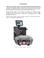
Introduction
3-DAS-1 is a pushbroom airborne scanner designed for high resolution aerial survey
with simultaneous image creation by three color channels. Nadir channel captures
ground surface images just below the aircraft and is used for automated creation of
orthophoto. Forward and backward channels capture images with 26º and 16º angles
along the flight direction providing permanent triple overlap for whole area.
Scanner 3-DAS-1 allows you to increase productivity and accuracy of digital
topographic maps based on aerial survey due to elimination of analogue photo
processing and their conversion to digital form for sequential work on digital
photogrammetric stations.
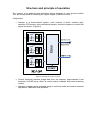
3-DAS-1 scanning system consists of 3-DAS-1 scanning unit, DAS Control Computer,
RAID array and operator’s display. (Figure1).
Figure 1: Components of 3-DAS-1 scanning system.
Structure and principle of operation
The scanner is an airborne optic-electronic device designed to scan ground surface
from an aircraft board for obtaining the digital images in real-time mode.
Composition:
•
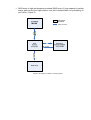
Scanner is a three-channel system, each channel of which contains lightsensitive CCD-sensor, optic-mechanical system, electronic system to control and
signal conversion. (Figure 2)
Figure 2: Flowchart of 3-DAS-1 scanner.
•
•
Control computer receives image data from the scanner, preprocesses it and
transfers it to RAID array. Also it is used to adjust, calibrate and control scanning
modes.
Operator’s display shows scanned image in real-time mode and controls scanner
adjustment, calibration and operation.
•
RAID array is high-performance protected RAID array of huge capacity to gather
image data during the flight mission and their transportation for processing to
your office. (Figure 3)
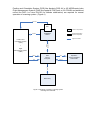
Figure 3: Flowchart of 3-DAS-1 scanning system.
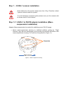
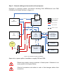
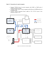
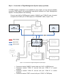
Position and Orientation System (POS) like Applanix POS AV or IGI AEROcontrol also
Flight Management System (FMS) like Applanix POSTrack or IGI CCNS4 and stabilized
mount like ASP-1 or Leica PAV30 (for attitude stabilization) are required for normal
operation of scanning system. (Figure 4)
IMU Data
IMU
3-DAS-1 components
EVENTS
SCANNER
3-DAS-1
IMU/GPS Navigation
System components
Signal connection
Image
Data/Control
Position and
Orientation System
(POS)
+
Flight
Management System
(FMS)
NMEA
VGA
Controll
Image Data
FCS
DAS
Control
Computer
RAID Array
Figure 4: Flowchart of 3-DAS-1 scanning system
including POS and FMS.
Operator’s
TOUCH SCREEN
LCD PANEL
Part 1. 3-DAS-1 hardware description
1.1. Hardware installation
To install scanning system, please do the following:
•
•
•
•
•
•
Step 1 – 3-DAS-1 scanner installation
Step 2 – Control computer installation
Step 3 – RAID-array installation
Step 4 – Operator’s display installation
Step 5 – General cabling and connection of board power
Step 6 – Connection of Flight Management System laptop (optional)
Please disconnect power when cabling.
Step 1 – 3-DAS-1 scanner installation
Some elements of the scanner weigh more than 15 kg. Therefore at least
2 persons should install the system.
To avoid damaging of optical system please never put the scanner with
its lenses down on soft surfaces.
Step 1-1: 3-DAS-1 to PAV30 adapter installation (Masscompensator installation)
Adapter (Mass-compensator) is needed for stabilizing mount PAV30 usage.
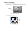
•
Mount mass-compensator housing on stabilized platform guiding by “Flight
Direction” sign. Be sure that flanges on the moving ring coincide with slots on the
mass-compensator housing. Fix it with four fixing screws. (Figure 1.1)
Figure 1.1: Mass-compensator housing.
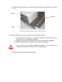
•
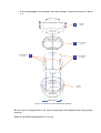
Put counterweights and top plate into the housing in sequence shown on figure
1.2.
Counterweight 2
2x 4.2 kg
2
4
Top plate
4.7 kg
3
Counterweight 3
5.7 kg
1
Counterweight 1
2x 9.7 kg
Frame
23.3 kg
Flight direction
Figure 1.2: Sequence of mass-compensator assembly.
Be sure that all components of the mass-compensator are fastened with fixing screws
securely.
Mass of assembled compensator is 61.4 kg.
Step 1-2: Scanner mounting on top of the mass-compensator
The scanner includes shock sensitive elements. Please perform all
operations slowly and carefully.
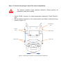
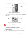
•
•
Mount 3-DAS-1 scanner on mass-compensator guiding by “Flight Direction”
sign.
Be sure that the scanner is in its unique position and fasten it with three fixing
screws. (Figure 1.3)
Flight Direction
Sign
Fixation
Screws
Fixation Screw
Fixation Holes
Fixation Hole
Flight direction
Figure 1.3: Mounting of the scanner on top of the mass-compensator.
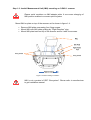
Step 1-3: Inertial Measurement Unit (IMU) mounting on 3-DAS-1 scanner
Please avoid scratches on IMU adapter plate. It can cause changing of
IMU position relative to scanner optical system.
Mount IMU on plate on top of the scanner as it’s shown in figure 1.4.
•
•
•
Remove IMU plate unscrewing four fixing screws.
Mount IMU onto IMU plate guiding by “Flight Direction” sign.
Mount IMU plate back on top of the scanner and fix it with four screws.
Figure 1.4: IMU mounting on 3-DAS-1.
IMU is not a product of SPE “Geosystem”. Please refer to manufacturer
to get installation manual.
Coordinates of IMU navigation center relative to the point of PAV30 platform axes
intersection (when mass-compensator used) for several IMU models are given in table
1.1:
Table 1.1: Coordinates of IMU navigation center
IGI
Axis
IMU-lld,
mm
Applanix LN200
With case,
mm
Without case,
mm
X
0,15
-5,01
-5,01
Y
-16,20
-14,84
-14,84
Z
-337,90
-341,03
-334,03
Axes direction:
X – forward, along flight direction;
Y – right;
Z – downward.
Step 2 – Control computer installation
Shocks and increased vibration can cause failure or its frozen-in
damages. Please perform all operations slowly and carefully.
To install control computer on-board use rack with damping elements.
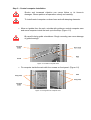
•
Move out guides from the rack, coincide with guides on control computer case
and move computer inside the rack up to the stop. (Figure 1.5)
Be careful during guide coincidence. Rough mounting can cause damage
of guide bearings.
Figure 1.5: Guide of computer case.
•
Fix computer inside the rack with four screws on front panel. (Figure 1.6)
Figure 1.6: Fixing holes of computer case.
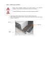
Step 3 – RAID-array installation
Shocks and increased vibration can cause failure or its frozen-in
damages. Please perform all operations slowly and carefully.
To install RAID-array on-board use rack with damping elements.
•
•
Unscrew two side fixers and move out in-out table from the rack.
Place RAID-array onto the table, coincide with fixing holes and screw fixing
screws. (Figure 1.7)
Figure 1.7: RAID-array mounting on in-out table of the rack.
•
Move in-out table with RAID-array up to the stop and fix it with two side fixing
screws. (Figure 1.8)
Figure 1.8: Fixing screws of the in-out table.
Step 4 – Operator’s display installation
Operator’s display is mounted to the rack with Velcro. To fix safely you should coincide
display table with contours of rack upper part and push tightly.
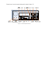
Step 5 – General cabling and connection of board power
Flowchart of scanning system connections including POS AEROcontrol and FMS
CCNS4 by IGI GmbH is shown in figure 1.9.
IMU
IMU
EVNT
INP
IGI
AEROcontrol
3-DAS-1 components
IMU/GPS
SYNC
EVENTS
IMU/GPS navigation
Syste components
SCANNER
3-DAS-1
AUX
28 V
DC IN
Power connection
28 V
DC IN
GRABBER
NMEA
FCS
CAMERA
LINK
Signal connection
Optional connection
R64 CL1
IGI
CCNS4
CAM1
or CAM2
28 V
DC IN
28 V
DC IN
5V, 12V
DC OUT
COM A
COM B
DAS
Control
Computer
VGA
or DVI
VGA
COM 1
TouchScreen
12 V
DC OUT
Monitor Power
PS/2
or USB
Operator’s
TOUCH SCREEN
LCD PANEL
LAN
KEYBOARD
SCSI
IN
RAID ARRAY
ARC6020
SCSI
OUT
TERMINATOR LVD/SE
5V, 12V
DC IN
SCSI
SCSI LVD
RAID Power
RS-232
POWER SPLITTER
Main
Power Cable
Control Computer Power
Scanner Power
AIRCRAFT
POWER
28 VDC
LAN
ETHERNET
PS/2
or USB
COM C
MOUSE
Figure 1.9: Flowchart of system connections.
Spare slot on power splitter is available to supply POS and FMS.
Please keep polarity during connection of board power. Otherwise it can
cause partial or full system failure.
Check all connectors and cables in order to find damages before their
connection.
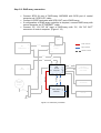
Step 5-1: Connection of control computer
•
Connect “COM A” port of control computer with CAM1 or CAM2 port of
CCNS4 unit via FCS cable.
Connect “COM B” port of control computer with AUX port of AEROcontrol unit
via NMEA cable.
Connect “Control Computer Power” cable to “28 V DC IN” input of the
computer. (Figure 1.10)
•
•
IMU
IMU
Power connection
EVNT
INP
IGI
AEROcontrol
IMU/GPS
SYNC
EVENTS
SCANNER
3-DAS-1
28 V
DC IN
AUX
Signal connection
Optional connection
NMEA
FCS
CAMERA
LINK
GRABBER
COM A
R64 CL1
IGI
CCNS4
28 V
DC IN
CAM1
or CAM2
5V, 12V
DC OUT
COM B
DAS
Control
Computer
VGA
or DVI
VGA
COM 1
TouchScreen
12 V
DC OUT
Monitor Power
PS/2
or USB
Operator’s
TOUCH SCREEN
LCD PANEL
LAN
KEYBOARD
SCSI
IN
RAID ARRAY
ARC6020
SCSI
OUT
TERMINATOR LVD/SE
5V, 12V
DC IN
SCSI
SCSI LVD
RAID Power
RS-232
POWER SPLITTER
Main
Power Cable
Control Computer Power
Scanner Power
AIRCRAFT
POWER
28 VDC
LAN
ETHERNET
PS/2
or USB
COM C
Figure 1.10: Connection of control computer.
MOUSE
General view of control computer back panel is shown in figure 1.11.
Figure 1.11: Control computer, back view.
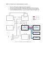
Step 5-2: RAID-array connection
•
Connect SCSI IN port of RAID-array ARC6020 with SCSI port of control
computer via “SCSI LVD” cable.
Connect LVD/SE terminator with SCSI OUT port of RAID-array.
If configuration of RAID-array controller is required, connect RAID-array with
control computer via “ETHERNET” cable.
Connect “5V, 12V DC IN” input of RAID-array with “5V, 12V DC OUT”
connector of control computer. (Figure 1.12)
•
•
•
IMU
IMU
Power connection
EVNT
INP
IGI
AEROcontrol
IMU/GPS
SYNC
EVENTS
SCANNER
3-DAS-1
28 V
DC IN
AUX
Signal connection
Optional connection
NMEA
FCS
CAMERA
LINK
GRABBER
COM A
R64 CL1
IGI
CCNS4
28 V
DC IN
CAM1
or CAM2
5V, 12V
DC OUT
COM B
DAS
Control
Computer
VGA
or DVI
VGA
COM 1
TouchScreen
12 V
DC OUT
Monitor Power
PS/2
or USB
Operator’s
TOUCH SCREEN
LCD PANEL
LAN
KEYBOARD
SCSI
IN
RAID ARRAY
ARC6020
SCSI
OUT
Figure 1.12: RAID-array connection.
TERMINATOR LVD/SE
5V, 12V
DC IN
SCSI
SCSI LVD
RAID Power
RS-232
POWER SPLITTER
Main
Power Cable
Control Computer Power
Scanner Power
AIRCRAFT
POWER
28 VDC
LAN
ETHERNET
PS/2
or USB
COM C
MOUSE
General view of RAID-array back panel is shown in figure 1.13.
Figure 1.13: RAID-array, back view.
Step 5-3: Connection of scanner operator’s console
•
•
•
•
Connect VGA cable of display with control computer.
Connect TouchScreen cable of display to COM1 port of control computer.
Connect display power cable to “12V DC OUT” socket of control computer.
Connect keyboard and mouse to control computer if required. (Figure 1.14)
IMU
IMU
Power connection
EVNT
INP
IGI
AEROcontrol
IMU/GPS
SYNC
EVENTS
SCANNER
3-DAS-1
28 V
DC IN
AUX
Signal connection
Optional connection
NMEA
FCS
CAMERA
LINK
GRABBER
COM A
R64 CL1
IGI
CCNS4
28 V
DC IN
CAM1
or CAM2
5V, 12V
DC OUT
COM B
DAS
Control
Computer
VGA
or DVI
VGA
COM 1
TouchScreen
12 V
DC OUT
Monitor Power
PS/2
or USB
Operator’s
TOUCH SCREEN
LCD PANEL
LAN
KEYBOARD
SCSI
IN
RAID ARRAY
ARC6020
SCSI
OUT
TERMINATOR LVD/SE
5V, 12V
DC IN
SCSI
SCSI LVD
RAID Power
RS-232
POWER SPLITTER
Main
Power Cable
Control Computer Power
Scanner Power
AIRCRAFT
POWER
28 VDC
LAN
ETHERNET
PS/2
or USB
COM C
Figure 1.14: Connection of scanner operator’s console.
MOUSE
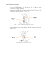
Step 5-4: Scanner connection
•
Connect GRABBER port of the scanner with R64 CL1 port of control
computer via CAMERA LINK cable.
•
Connect “IMU/GPS SYNC” output of the camera to “EVNT INP” input of POS
AEROcontrol via EVENTS cable. (Figure 1.15)
Figure 1.15: Scanner: GRABBER and IMU/GPS SYNC interfaces.
•
Connect “Scanner Power” power cable to “28 V DC IN” input of the scanner.
(Figure 1.16)
Figure 1.16: Scanner: power connector and fuse.
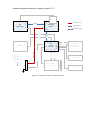
Scanner connection scheme is shown in figure 1.17.
IMU
IMU
Power connection
EVNT
INP
IGI
AEROcontrol
IMU/GPS
SYNC
EVENTS
SCANNER
3-DAS-1
28 V
DC IN
AUX
Signal connection
Optional connection
NMEA
FCS
CAMERA
LINK
GRABBER
R64 CL1
IGI
CCNS4
28 V
DC IN
CAM1
or CAM2
5V, 12V
DC OUT
COM A
COM B
DAS
Control
Computer
VGA
or DVI
VGA
COM 1
TouchScreen
12 V
DC OUT
Monitor Power
PS/2
or USB
Operator’s
TOUCH SCREEN
LCD PANEL
LAN
KEYBOARD
SCSI
IN
RAID ARRAY
ARC6020
SCSI
OUT
TERMINATOR LVD/SE
5V, 12V
DC IN
SCSI
SCSI LVD
RAID Power
RS-232
POWER SPLITTER
Main
Power Cable
Control Computer Power
Scanner Power
AIRCRAFT
POWER
28 VDC
LAN
ETHERNET
PS/2
or USB
COM C
Figure 1.17: Scheme of 3-DAS-1 scanner connection.
MOUSE
Step 6 – Connection of Flight Management System laptop (optional)
If CCNS4 system component is not available for any reason you can connect portable
computer (FMS laptop) with preinstalled specialized software as Flight Management
System. For that please do the following:
Connect port AUX of AEROcontrol module, “COM A” and “COM B” ports of control
computer and COM1 port of FMS laptop via “FCS/NMEA” cable. (Figure 1.18)
Figure 1.18: Connection of Flight Management System laptop.
•
•
•
•
Connector marked “NMEA” connect with port “AUX” of AEROcontrol.
Connector marked “COM A” connect with port “COM A” of control
computer.
Connector marked “COM B” connect with port “COM B” of control
computer.
Connector marked “FMS” connect with port “COM1” of FMS lptop .
1.2. Turning on sequence
AEROcontrol and CCNS4 systems are not products of SPE
“Geosystem”. Please refer to manufacturer to get installation manual.
•
Move switch on the right side of the rack to position «1». (Figure 1.19)
Figure 1.19: Main power switch.
•
Turn on scanner, moving switch “Power” on its case to position «1» (Figure 1.20)
Figure 1.20: “Power” switch and indicator of the scanner.
“Power” indicator and 5 indicators of scanner internal voltages have to light up. (Figure
1.21)
Figure 1.21: Indicators of scanner internal voltages.
•
Open protective cover on control computer with computer case key and press
“Power” button for a short time. (Figure 1.22)
Figure 1.22: Cover in open state and “Power” button.
RAID-array and operator’s display will be switched on with control computer
automatically.
•
You can start working after OS loading complete.
1.3. Turning off sequence
AEROcontrol and CCNS4 systems are not products of SPE
“Geosystem”. Please refer to manufacturer to get installation manual.
Having finished mission:
•
Turn off scanner, moving switch on its case to position «0». (Figure 1.20)
•
Select “Turn off” item from “Start” menu on control computer and wait until OS
will finish its work.
RAID-array and operator’s display will be switched off with control computer
automatically.
•
Move switch on the rack to position «0» for board power disconnection. (Figure
1.19)
1.4. Transferring data to other computer
•
•
Be sure that control computer is turned off.
Release RAID-array in-out table, having unscrewed 2 fixing screws on front of
the rack, and move it out up to the stop. (Figure 1.23)
Figure 1.23: Fixing screws of the in-out table.
•
Disconnect all cables on RAID-array back panel (i.e. SCSI cable, power cable
and ETHERNET cable if connected).
Figure 1.24: RAID-array, back view.
•
Remove RAID-array from in-out table having unscrewed 4 fixing screws. (Figure
1.25)
Figure 1.25: Removing RAID-array from in-out table of the rack.
To connect RAID-array to office computer you should have the next:
1) AC power cable with Euro or US plug according to socket type in your
office (see list of components supplied);
2) Adapter for external SCSI-devices with drivers required (not supplied);
3) External SCSI-cable (it is analogue to component supplied).
If your cable has “Terminator” impedance matcher, you should remove
terminator installed on “SCSI OUT” port of RAID-array.
•
Put RAID-array on plane and solid surface.
•
Place power loopback to “5V, 12V DC IN” connector of RAID-array. (Figure 1.26)
Figure 1.26: Power loopback in “5V, 12V DC IN” connector.
•
Be sure that value set by switch on RAID-array back panel corresponds to
voltage in AC network in your region. Both variants are possible: 110V or 220V
(Figure 1.27)
Figure 1.27: Back panel with voltage selector and input power switch.
Connection to AC network with incorrectly set voltage value can cause
frozen-in damage of the RAID-array.
•
•
•
•
Connect “SCSI IN” port of RAID-array with corresponding port of office computer.
Connect RAID-array to AC power using AC power cable.
Move switch on back panel of the RAID-array to position «1». (Figure 1.27)
Turn on RAID-array by pressing “Power” button on front panel and wait for it’s
initialization to be finished.
An IP address will be shown on LCD of the RAID-array when initialization complete.
•
Turn on computer.
After OS loaded you can transfer data from RAID-array via copying.
Part 2. DAS software operation manual.
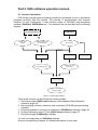
2.1. General information
DAS image recording and processing workflow is performed by set of specialized
programs provided with the camera. The process is semiautomatic and requires
minimum of user interference. It also involves usage of GPS/IMU post-processing
software (POSPack, AEROoffice etc.). The workflow can be described by the following
diagram:
GPS/IMU postprocessing software
Event time
stamps
DASControl
WGS’84 trajectory
& orientation
Raw image
POSExtract
DASCorrect
Strip attitude files
Calibration and
LUT files
DASView
DASRectify
Geo-referenced
rectified image
Figure 2.1: DAS image workflow
Thus whole process can be divided into following steps:
1. Recording image (DASControl software) and navigation data (Navigation
software) (page 35)
2. Retrieving high accuracy trajectory and orientation (GPS/IMU post-processing
software)
3. Extracting attitude for the each recorded strip (POSExtract software) (page 36)
4. Creating calibration and LUT files (DASCorrect software) (page 37)
5. Rectifying image (DASRectify software)
To view raw image data use DASView software.
Review corresponding chapters for detailed description of each step.
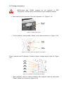
2.2. Recording image with DASControl software
The main purpose of DASControl software is to set up camera and record image
during flight mission. The program’s interface is designed for use with touch screen; it
allows to perform all necessary operations without keyboard and a mouse.
The program creates a project folder in “YY-MM-DD_hh-mm-ss” format to save all
taken image data. This folder is used by DASCorrect and DASRectify software
afterwards. Every new flight mission should be started within new project folder.
Following step by step instructions describe the software’s principle of operation.
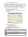
2.2.1. Preliminary preparation / before take-off
Turn on the computer and the camera
Check system operability: make sure the DASControl program is running with
no warning messages.
- Select Files sheet
-
2
3
1
4
5
6
Figure 2.2: DASControl software, “Files” sheet
-
-
Make sure the current settings are correct:
o Check all required cameras (1)
o Select preferred bit depth for each camera (2)
o Select required color channels (3)
o Select required compression method (4)
Make sure RAID has enough free space for new mission data (6)
Press New project (5) button to create new project folder.
Turn off the computer.
It’s highly recommended NOT to use RAID as storage for previous
mission’s data as well as any other information. It is advisable to start new
mission with empty, formatted RAID to avoid data fragmentation since it
cause speed degradation and stop writing the data.
It is highly recommended to take-off and land with turned off computer
and RAID, since jerks can damage hard disks.
-
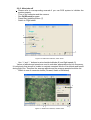
2.2.2. After take-off
Please refer to corresponding manuals if you use POS system to initialize the
system properly.
Turn on the computer and the camera.
Run DASControl program
Press Start grabbing button (7)
Switch to Flight sheet
9
8
7
Figure 2.2: DASControl software, “Files” sheet
Use “+” and “–” buttons to set scheduled altitude (8) and flight speed (9)
Values of altitude and speed are used to calculate appropriate scan line frequency.
It is obviously that aircraft is unable to maintain constant values of its altitude and speed
during flight line. Therefore the average altitude and the average speed should be set.
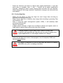
- Switch to one of camera’s sheets (Forward, Nadir or Backward)
-
9
8
Figure 2.3: DASControl software, camera sheet
10
-
Press the Autotune (8) button to adjust video signal amplification. It will take
some time to complete. Use “+” and “–” buttons (9) to adjust amplification
manually. Changing it within current camera sheet will affect the rest cameras.
Watch histogram and image waterfall. Amplification changes are reflected there
immediately.
2.2.3. On the flight line
-
When you are about to enter new flight line start image data recording by
pressing Start writing button (10).
When current flight line is finished, stop image data recording by pressing Stop
writing button (10).
Note: if using the flight management system (FMS), it will start/stop data
recording automatically.
Repeat if necessary
If flight mission consists of flight lines of different altitude and speed, switch to
Flight sheet to adjust these values every time they change.
Changing altitude or speed values causes camera to change scan
frequency and exposition time. Therefore it is necessary to adjust video
signal amplification every time flight conditions are changed.
-
When the last flight line is done, close program, turn off computer, RAID and
camera before landing.
It is highly recommended to take-off and land with turned off computer
and RAID, since jerks can damage hard disks.
2.3. Processing the navigation data with POSExtract software
Standard output of any navigation systems is represented by flight trajectory and
orientation data for whole flight mission. The main purpose of POSExtract program is to
extract useful navigation data which corresponds to recorded strips. It also interpolates
navigation data to get 1 attitude record per each image line. POSExtract creates set of
attitude files which are required for rectification process.
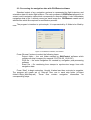
The program’s interface is quite simple. It is represented by 3 fields to be filled by
user:
Figure 2.4: POSExtract software, main window
Press “Browse” buttons to select the following items:
Project folder – the root folder created by DASControl software which
contains all strip’s images (for example “D:\07-06-25_13-00-00”)
POS file – the main navigation file created by navigation post-processing
software
Event file – file containing time stamps to synchronize image lines with
navigation data.
Press “Start” to begin extraction. Usually it takes less then a minute to complete.
The program will create set of “Strip.att” files, one in each strip folder (<Project
folder>\<Strip_NN>\Strip.att). These files contain navigation information for
corresponding strips.
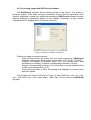
2.4. Processing image with DASCorrect software
The DASControl software stores scanned image in raw format. That allows to
preserve original 14-bit depth and gives possibility to pick the best parameters (like
gamma, brightness, contrast etc) while post-processing. DASCorrect software chooses
optimal radiometric parameters based on the statistic information. It also creates
calibration files for dodging and CCD sensor uniformity.
Figure 2.5: DASCorrect software, main window
Follow next steps to process a project:
Press Browse button and select the root folder created by DASControl
software containing all strip’s images (for example “D:\07-06-25_13-00-00”)
Program will display all projects’ strips. You can exclude some from
processing if necessary. Uncheck corresponding checkbox to do this.
Uncheck corresponding checkbox if you don’t want to create calibration files
(CLB) or look-up table files (LUT),.
Press Process button to start. Processing time depends on project’s size
and HDD speed.
The program will create CLB and LUT files for each RAW file (r.clb, r.lut, g.clb,
g.lut, b.clb and b.lut) in the same folder. These files will be used by DASRectify
program.
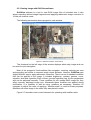
2.5. Viewing image with DASView software
DASView software is a tool to view RAW image files of unlimited size. It also
allows exporting defined image fragments and applying radiometric image correction in
16-bits per channel mode.
The following screenshot shows program’s main window.
Figure 2.6: DASView software, main window
The thumbnail at the left edge of the window displays whole strip image and can
be used for quick navigation.
Most of the program’s functionalities (like navigation, zooming, selecting an area
and exporting) are similar to common image viewer software. However, DASView uses
slightly different way to apply radiometric correction. There is a set of standard modifiers
that can be applied to the image. It includes brightness, contrast, gamma, curve,
equalize, level and logarithm. Each of them (except logarithm) has its own parameters
and can be adjusted manually. These modifiers do not update RAW image file; they
affect currently displayed image only. Afterwards these modifiers are applied during
rectification. It is possible to add as many modifiers as necessary; therefore it’s
important to define the order of applying. “Modifier stack” is used for these purposes.
Modifiers will affect image in the order they was placed in stack.
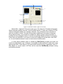
Figure 2.7 describes main control elements for operating with modifier stack.
1
2
5
6
7
4
8
3
Figure 2.7: DASView software, “Adjust LUT” window
Select Edit – Adjust LUT from the main menu. The Adjust LUT window will appear.
Select required modifier from the Current modifier list box (1) and color channel (2). Set
value for selected modifier (for example, Gamma = 0.6) and press Push (3) button to
save the modifier in stack. One can add as many modifiers as necessary in that way.
Once added to stack, any modifier is available for editing. Select required modifier in
modifier list (5) to change its value. It can be removed by Delete (4) button if necessary.
Press Clear all (6) button if you want to remove all modifiers from the stack. Use Save
as (7) and Load (8) buttons to save or load current modifier stack.
In most cases modifier stack is created by DASCorrect program and does not
need to be adjusted by user. However, it is possible to edit existing or create new, more
appropriate stack. Press Save as (7) button while holding Ctrl key to generate new LUTfiles based on current stack. LUT-files will be used by DASRectify software during
rectification process.
Appendix A
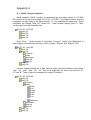
A.1. 3-DAS-1 project structure.
Each separate 3-DAS-1 project is represented by one folder named in “YY-MMDD_hh-mm-ss” format (for example “07-01-20_13-00-00”). This folder contains as many
subfolders as flight lines in the flight mission, i.e. one subfolder for each strip. These
subfolders are named “Strip_XX”, where XX – order number starting from 01. Thus,
usual project have the following look:
07-01-20_13-00-00
Strip_01
Strip_02
Strip_03
Strip_04
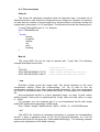
Each “Strip…” folder contains 3 subfolders “Forward”, “Nadir” and “Backward” to
save image from respective cameras. It also contains “Strip.att” and “Map.inf” files.
07-01-20_13-00-00
Strip_01
Strip_02
Forward
Nadir
Backward
Strip.att
Map.inf
Strip_03
Strip_04
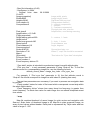
Camera folders contain set of files with the same name and different extensions:
“raw”, “inf”, “map”, “bbs”, “clb”, “lut”. This set is duplicated for each color channel: “R”,
“G” and “B”. There is also one separate file named “Default.cc”
07-01-20_13-00-00
Strip_01
Strip_02
Forward
Nadir
R.raw
R.inf
R.map
R.bbs
R.clb
R.lut
…
Default.cc
Backward
Strip.att
Map.inf
Strip_03
Strip_04
A.2. Files description
Strip.att
This binary file represents navigation data for respective strip. It contains set of
attitude structures; each structure corresponds to one image line. Number of records is
not less than the number of saved image lines. Synchronization of attitude records and
image lines is discussed in “x.inf” description. The attitude record has the following form:
// sizeof(TAttitudeRecord)= 6 * 8 = 48 bytes
struct TAttitudeRecord
{
double
latitude,
longitude,
altitude,
roll,
pitch,
heading
};
Map.inf
This small ASCII file can be used to operate with “*.map” files. The following
example describes file structure:
3
166 2681
49.219090 28.580882 1177.60
49.231968 28.529308 1180.01
(current strip number)
(width and height of map image)
(latitude, longitude and altitude of strip entry point)
(latitude, longitude and altitude of strip exit point)
*.raw
Raw-files contain saved the image itself. File format depends on the used
compression method. Read the corresponding “*.inf” file in order to find out
compression method (or any other image related information). Only non-compressed
file format is discussed below. Use specialized library to read packed or compressed
file.
Non-compressed raw-file is a plain grayscale image, an array of pixel values
without header. Each pixel is represented by 2-byte value and has value in range
0…16383.
For example, one can calculate size of a non-compressed raw-file with image
width 8002 pixels and image height 10’000 pixels:
Size = Width * Height * BytesPerPixel = 8002 * 10’000 * 2 = 160’040’000 bytes
*.inf
This ASCII file contains all necessary information to process the corresponding
raw-file. It have a standard format of “Ini” file for Microsoft Windows, so it can be
accessed with Win-API functions like “GetPrivateProfileString()”. The following example
gives some explanations of file fields meaning:
; Raw file information (v0.83)
; GeoSystem (c) 2004
; Original scan date: 29.10.2006
10:44:33
[Image properties]
Width=8002
Height=43680
Color depth=14
Compression=0
Pixel size=9
Amplification=+ 15.3 dB
[Flight properties]
Height above ground=900
Height unit=0
Speed over ground=180
Speed unit=0
Focal distance=110
Camera angle=0
Scale=8181.82
Resolution=7.36
Map=1
[Sync data]
First sync line=18
Event number=1
Event frequency divisor=72
Image width, pixels
Image height, pixels
Significant bits per pixel
Compression method (
0 – without compression,
1 – packed
2 – lossless compression)
Physical pixel size, microns
Amplification, used during scanning
0 – meters, 1 - feets
0 – kmh, 1 - knots
Focal distance, mm
Angle, degrees
Ground pixel size, cm
When 0, “map” file should be recreated
*See below for “Sync data” description
“Sync data” section is intended to synchronize image lines with attitude data.
“First sync line” – is only necessary parameter if using “Strip.att” file. To find the
attitude record for a corresponding image line, use the following formula:
attitude_record_index = image_line_index + first_sync_line
For example, if “First sync line” parameter is 18, the first attitude record in
“Strip.att” file should correspond to image line with index 18 (starting from zero).
The rest two parameters are necessary if you want to process raw navigation data
by yourself.
“Event number” states for index of first event which corresponds current strip within
the whole flight mission.
“Event frequency divisor” shows how many times line frequency is greater then
event frequency. To obtain time value for each image line one should interpolate event
time values.
*.map
Map-file contains thumbnail of saved image for quick review and navigation with
Sea.exe. Scale factor of thumbnail image is 48. Map-file is plain grayscale image, an
array of pixel values without header. Each pixel is represented by 1-byte value and has
value in range 0…255.
*.bbs
This file is present only if lossless compression is used. File is used by Sea.exe
and DASImage library for quick access to compressed images and does not require to
be processed by end-user.
*.clb
This is binary line sensor calibration file. It contains factors which are to be applied
(multiplied) to CCD pixels. Each factor is represented by float value (4 bytes) not less
then 1.0. Since file contains 1 value for each image line pixel, its size is always
constant: 8002 pixels * 4 bytes = 32’008 bytes.
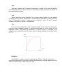
*.lut
Since raw-file is always store raw unadjusted image, lut-file is used for radiometric
correction before displaying image. It contains lookup table for whole range of pixel
brightness values. This binary file consists of 2N values, where N – bit depth of an
image (can be retrieved from inf-file). Each value is 2-bytes unsigned value within range
0…2N-1.
Value
2N - 1
Index
0
2N - 1
Default.cc
This ANSI file is used to create corresponding LUT-files. It contains information
concerning different color correction modifiers like brightness, contrast, gamma etc. Use
Sea.exe to edit Default.cc and create LUT-files.
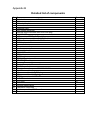
Appendix B
Detailed list of components
№
1
2
3
Name
Digital airborne scanner 3-DAS-1
Mass-compensator
IMU adapter plate
Quantity
1
1
1
4
5
6
7
8
9
10
11
Computer rack
DAS control computer
External RAID-controller ARC6020 with plug
400 GB HDD
LCD-monitor AEGIS with TouchScreen panel
USB keypad compatible with OS Windows
USB mouse compatible with OS Windows
FMS Laptop stand
1
1
1
5
1
1
1
1
12
Computer case key
2
13
14
15
16
17
18
19
20
21
22
23
24
25
26
27
28
Camera Link cable
FCS/NMEA cable
FCS cable
NMEA cable
SCSI LVD exterior cable
ETHERNET cable
Scanner Power cable
Control Computer Power cable
RAID Power cable
Adapter of monitor power RA9000XC1594
Main Power cable
AC power cable with EURO plug
AC power cable with US plug
DB9M connector with DP-9CC cover
LVD/SE terminator
10 А fuse
1
1
1
1
1
1
1
1
1
1
1
1
1
1
1
10
29
30
31
32
Scanner specification
Calibration Certificate
User’s manual for AEGIS monitor
This user’s manual
1
1
1
1