1
Facultad de Informática
Informatika Fakultatea
DEGREE:
Technical Engineering in Systems Computer Science
S
Reuse of software components
orientated to iOS mobile devices
Student: Xabier Moraza Erauskin
Student:
Director: Alejandro García-Alonso
Alonso Montoya
End of Career Project, 23rd May 2013
Acknowledgments
Thank you Álex for telling me about my faults and for giving me ideas
while I was writing the report. Thank you as well for giving me the
chance to make the project in IK4-Ikerlan and for being such a good
tutor. Thank you Juanpe for helping me integrate in the company and for
introducing me all the people that afterwards have helped me to develop
this application. I would like to give special thanks to Blanca, Aitor, Igor
and Jone for giving me such a good technical support every time I
needed despite they were usually busy. Thank you as well all the guys in
the software technologies department of IK4-Ikerlan for letting me share
their coffee-time with them and for being so kind with me, I felt really
comfortable working with them. Thank you all the people in the
company that I have met, especially during the lunch time, for making
this time more entertaining.
Finally, thank you all the people that helped me during the development
of this project and I am sorry if I forgot to mention someone.
THANK YOU SO MUCH!
RESUMEN
El objetivo de ésta memoria es describir lo más detalladamente posible el
proyecto realizado éstos últimos meses para la empresa IK4-Ikerlan. Se trata del
desarrollo de una aplicación basada en sockets para dispositivos móviles de la
familia Apple, cuyo sistema operativo se denomina iOS y que es junto con
Android el sistema operativo más utilizado del mundo en lo que a dispositivos
móviles se refiere.
Ésta aplicación está disponible en la App Store y existe una versión para
iPhone, y otra para iPad. Decidimos descartar la aplicación para Apple TV, ya
que no contábamos con ningún dispositivo o simulador para probarla.
Cabe destacar que el objetivo del proyecto no es el de crear una
aplicación desde cero, sino que la idea es la de coger la lógica de una aplicación
para Android y trasladarla a iOS. Para ello, ha sido necesario convertir código
Java en Objective-C, lenguaje con el que se programan todo tipo de aplicaciones
para dispositivos de Apple, ya sean portátiles o de sobremesa. Gracias a una
herramienta todavía en fase de desarrollo y creada por Google, llamada j2ObjC,
ésta tarea ha resultado más fácil de lo que hubiera supuesto traducir estos
códigos a mano.
ABSTRACT
Within the next few pages, I will try to give a wide description of
the project that I have been doing for IK4-Ikerlan. For the last six
months, I have been working in developing a socket-based application
for Apple devices. These devices work under the iOS operative system,
which is programmed in Objective-C, a language similar to C.
Although I did not have the chance to develop this application for
Apple TV, I was able to create an application for iPhone and another one
for iPad. The only difference between both applications was the screen
resolution, but we decided to make them separately, as it would be really
hard to combine both resolutions, and wallpapers, everything in the same
workspace.
Finally, it is necessary to add that the main goal was not to create
a new application for iOS, but to translate an Android application into
iOS. To achieve this, it is required to translate Java code into ObjectiveC, which is the language used to develop applications for all kinds of
Apple devices. Fortunately, there is a tool created by Google, which
helped us with this exercise. This tool is called j2ObjC, and it is still
being developed.
LABURPENA
Memoria honetan azken hilabeteetan garatutako aplikazioaren
ezaugarri guztiak azaltzen saiatuko naiz. Proiektu hau IK4-Ikerlan
enpresan garatu dut. Azalduko dudan proiektuaren helburua dispositibo
mugikorretarako aplikazio bat garatzea izan da. Aplikazio hau iOS
sistema eragilerako pentsatuta dago, hau da, Apple familiako dispositibo
mugikorrentzat eta socket bidezko konexioetan oinarrituta dago.
iPhone eta iPad-erako aplikazio bana egitea pentsatu genuen
lantaldean, bakoitzak erabiltzen zituen irudien resoluzioak desberdinak
zirelako, eta, beraz, zaila gertatuko zelako biak kode berean integratzea.
Apple Tv-rako aplikazio bat garatzea ere pentsatu genuen, baina
dispositiborik edota simulatzailerik ez genuenez, ideia bertan behera
uztea erabaki genuen.
Esan beharra dago, proiektuaren helburua ez dela iOS-erako
aplikazio bat nahierara garatzea izan, baizik eta aurretik garatutako
Android-eko aplikazio bat eredutzat hartuz, logika guztia iOS-era
itzultzea. Horretarako, Java-n idatzitako kodea Objective-C ra pasatzea
beharrezkoa izan da, pauso hau proiektuaren muina delarik. Ataza hau
errazteko, j2ObjC izeneko tresna bat erabili dut. Tresna hau Google-ek
sortu zuen eta oraindik garatze-prozesuan dago.
INDEX
1
INTRODUCTION ..........................................................................................1
1.1
Project objectives .....................................................................................................1
1.2
Tasks list ..................................................................................................................2
1.2.1
Deliverables list ...........................................................................................3
1.3
Risks.........................................................................................................................4
1.4
Planning ...................................................................................................................5
1.4.1
Advance Table .............................................................................................5
1.4.2
GANTT table ...............................................................................................6
1.5
Document’s structure ...............................................................................................6
1.6
Work methodology ..................................................................................................7
2
BACKGROUND ............................................................................................9
2.1
Android ..................................................................................................................10
2.2
IOS: first steps .......................................................................................................12
2.3
IOS: User I/F ..........................................................................................................13
2.4
IOS: sockets ...........................................................................................................14
2.5
IOS: learned experiences for developers ...............................................................15
2.6
Review of related documents .................................................................................16
3
PROTOTYPE: IOS USER I/F ......................................................................21
3.1
Sample application .................................................................................................21
4
PROTOTYPE: IOS COMMUNICATIONS .................................................25
4.1
REST Protocol .......................................................................................................25
4.2
SOAP Protocol .......................................................................................................25
4.3
Sample application (calculator) .............................................................................26
4.3.1
Using wsdl2objc to export code from a wsdl ............................................28
4.3.2
Parsing the wsdl .........................................................................................30
4.3.3
Received data .............................................................................................32
4.3.4
Customizing the SOAP request .................................................................32
4.3.5
Used libraries and tools..............................................................................32
5
MSECURITY IOS APPLICATION .............................................................35
5.1
Application requirements .......................................................................................35
i
5.2
5.3
5.4
User I/F ..................................................................................................................36
5.2.1
The autorotation problem...........................................................................36
5.2.2
Phone calls .................................................................................................37
5.2.3
E-mail.........................................................................................................38
5.2.4
Porting from iPhone to iPad ......................................................................40
5.2.5
Used libraries .............................................................................................41
5.2.6
Using a singleton to manage global variables ...........................................41
Architecture ...........................................................................................................43
5.3.1
User interface’s class diagrams (storyboard) .............................................43
5.3.2
Socket server’s class diagrams ..................................................................49
5.3.3
The link between the Services Centre and the house (class diagram) .......51
Communications ....................................................................................................52
5.4.1
Sockets .......................................................................................................52
5.4.1.1
Initial objectives and background ..............................................................52
5.4.1.2
Extended description..................................................................................53
5.4.1.3
Types of possible messages received from the socket server ....................54
5.4.1.3.1
Echo (Keep alive) ................................................................................54
5.4.1.3.2
Or .........................................................................................................54
5.4.1.3.3
Notification ..........................................................................................55
5.4.1.3.4
Alarm ...................................................................................................55
5.4.1.4
Managing background and foreground modes ..........................................55
5.4.1.5
Using j2ObjC to translate code ..................................................................56
5.4.1.6
Ported libraries and code from Java ..........................................................58
5.4.1.7
Used libraries and tools..............................................................................60
5.4.1.8
Final results ................................................................................................62
5.4.2
Web service................................................................................................63
5.4.2.1
Initial objectives and background ..............................................................63
5.4.2.2
Extended description..................................................................................63
5.4.2.3
From the WSDL to the parsed data ............................................................64
5.4.3
The house ...................................................................................................64
6
CONCLUSIONS AND FUTURE LINES ....................................................67
6.1
Final Results ..........................................................................................................67
ii
6.2
Personal conclusions ..............................................................................................68
6.3
Future lines ............................................................................................................68
7
BIBLIOGRAPHY .........................................................................................71
Appendix I
Basic Objective-C experiences
Appendix II
Application User Manual
Appendix III Application Installation Manual
Appendix IV Uploading an app to the App Store
Appendix V Glossary
iii
iv
INDEX OF FIGURES
Figure 1 Tasks diagram..................................................................................................... 3
Figure 2 AndroidManifest.xml file .................................................................................. 10
Figure 3 Adding a new activity....................................................................................... 11
Figure 4 Graphical description of a socket connection................................................... 15
Figure 5 First view controller (implementation file and simulator screenshot) ............. 21
Figure 6 “Ahead” message ............................................................................................. 22
Figure 7 Table View Implementation ............................................................................. 22
Figure 8 View Controller’s attributes ............................................................................. 23
Figure 9 Application’s main storyboard ......................................................................... 23
Figure 10 Screenshot of the sample application ............................................................. 27
Figure 11 SOAP request and response messages ........................................................... 27
Figure 12 Using a web service ........................................................................................ 30
Figure 13 “getMensajes” SOAP response ...................................................................... 31
Figure 14 “didStartElement” for “getMensajes” request ................................................ 31
Figure 15 Designing a phone call screen programmatically........................................... 37
Figure 16 Making a call from an iPhone ........................................................................ 38
Figure 17 E-mail screen appearance ............................................................................... 39
Figure 18 Creating an instance of MFMailViewController ............................................ 39
Figure 19 “hideTabBar” method for iPad ...................................................................... 40
Figure 20 “hideTabBar” method for iPhone................................................................... 41
Figure 21 Variable Store definition ................................................................................ 42
Figure 22 Setters and getters in the singleton ................................................................. 42
Figure 23 Synthesizing the elements .............................................................................. 43
Figure 24 Reading and writing ....................................................................................... 43
Figure 25 First Screens ................................................................................................... 44
Figure 26 Tab Bar Controller.......................................................................................... 45
Figure 27 Scene, manual control and messages view controllers................................... 46
Figure 28 Relationship between tab bar, navigation and view controllers ..................... 46
Figure 29 Alarma table view controller and alarma detail view controller .................... 47
Figure 30 New alarm dialog ........................................................................................... 47
v
Figure 31 Scene change process ..................................................................................... 48
Figure 32 Pictures management ...................................................................................... 49
Figure 33 Relationship between the device and the services centre ............................... 50
Figure 34 State machine ................................................................................................. 50
Figure 35 Communications class diagram ...................................................................... 51
Figure 36 Adding all the jar files to the classpath .......................................................... 57
Figure 37 Local notification pop-up in iPad .................................................................. 62
Figure 38 The GuruPlug device used in this project ...................................................... 65
vi
INDEX OF TABLES
Table 1 Advance table ...................................................................................................... 5
Table 2 GANTT table for this project .............................................................................. 6
Table 3 Java to Objective-C translation (available libraries in j2ObjC 0.7) .................. 59
vii
viii
1 INTRODUCTION
The result of this project has been a socket-based iOS application. This application can
be run in the latest versions of iOS. The name of the app is mSecurity (a version of this
application was developed for Android before starting with this project and it was called
mSecurity). With this application, user will be able to take control of some devices in
his/her house and change their status anywhere he/she is. The user will also receive a
notification of every alarm that is forced in the house while the user is not at home.
Some other functionalities are described in depth later on.
The first aim was to reuse as much software components (from the Android’s
application code) as we could, but we soon realized that some important parts of the
code were not reusable, for example, the User Interface. For this reason, the User
Interface was started from scratch, but always trying to keep a similar appearance in the
iOS app and in the Android one. Other parts, such as the socket client have been ported
directly from Java to Objective-C.
To implement all these things, I used an iMac with Mac OS X operative system. At the
same time, I used Xcode IDE for writing the code. The language used to develop apps
for any Apple device is called Objective-C. I had never worked with this language
before this project, so I had to learn the tricks of it. In order to do it, I looked for
information on the Internet. However, newest versions of Xcode make things much
easier for the developer.
For translating the code from Java (Android) to Objective-C (iOS), I used a tool called
j2ObjC. This tool was created by Google, but it's still being developed, so it has been
necessary for me to translate some parts of the code manually. To achieve this, I had a
look at some Java manuals and tutorials about j2ObjC like the one shown in the Google
Inc. (2013) repository.
The first idea was to create a universal app that could be used in both devices, but it
resulted messy and difficult to manage with different resolutions in the same code, so
we decided to create two different apps, one for each device. Applications are created
for iOS 6, but it is possible to run them in earlier operative systems, as long as they are
iOS operative systems. However, the mSecurity application is not available on the App
Store, as we could not upload it due to the Apple’s restrictions.
1.1 Project objectives
The developed application is a socket-based application that will be used to protect the
users home even when the user is away. For that, user will be able to choose between
four scenes (home, away, night and holiday). In each scene, the sensors in the house
will have a different status. A table with the list of items’ status can be seen by touching
the scene icon. For example, if the user is away, the movement detector will be on and
will send an alarm if someone tries to get into the house. If the user is at home, the
detector will be off, and alarms will not be sent.
User will also be able to change the status of a device in any of the four scenes. These
orders will be sent to the server and the server will change the status of the devices.
1
When the order is executed, the server should return a notification to the mobile device
notifying if the action has been finished successfully or not. Notifications will be
divided in three groups. Alarms, system alerts and notifications. When an alarm comes
to the device, a pop-up window will be raised, even if the app is in background mode. In
this case, a universal pop-up will be raised first and then, if the “OK” button is pressed
the app will be “launched” with the pop-up view controller. If not, the first notification
will stay in the device’s notification pane. If several notifications come and the user
does not open any of them, the first one that will appear will be the oldest notification.
User will be able to see all the messages received, divided in 5 groups (alarms, system
alerts, notifications, pictures, and all the messages). The last group will store all the
messages, but user will not be able to see each message’s details from here. On the
other hand, the rest of the groups will have a detail view controller to see each
message’s details by clicking on a cell. If a message is still not read, that message’s cell
will be darker. Once the detail’s view controller is opened, that selected cell in the table
will be brightened.
As it was said before, when an alarm comes to the device, a pop-up window will appear.
This window will show the user some details of the new alarm, such as the description,
the time, or the date. When user skips these view controllers, he/she will have the
chance to send an e-mail, make a phone call, or ask for some pictures. After the user
makes the acknowledgement by clicking on a couple of buttons, the app will go back to
the messages screen and the new alarm will appear in the alarms table view.
The app will always be active, obviously, except the first time that it is launched. For
the app’s first launch the app will load all the data from the web service, including
scenes, devices status or users’ information. User will need to authenticate by writing a
four-digit pin number in the login view controller. The valid pin number will come from
the web server. The web server will return a different number depending on the MAC
number of the mobile device, which will be registered in a database. If the MAC
number of the device is not registered, the pin will not be transmitted and login will not
be possible. Once the user has entered the valid pin number, the system will open the
socket connection and if authentication goes well and there is not a problem with the
connection, the scenes view controller will be shown. If a problem occurs, the app will
keep loading until the socket connection is opened. If the application is executing and
internet connection is lost, app will keep trying to connect until the connection returns.
At this point, authentication process will be repeated.
1.2 Tasks list
We consider two task types: tactical and operative. They are described in the following
points:
• Tactical TASKS
o File management
o Meetings
o Planning
• Operative tasks
o To study the background required
2
o To build an application to test I/F building
o To build an application to test communications
o To port the application from Android to IOS
• Analysis
• Design
• Implementation
• Testing
o Documentation
Project
Tactical tasks
File
management
Planning
Operative tasks
Meetings
Background
study
Communications
testing
IF Testing
Analysis
Design
Application
porting
Documentation
Implementation
Testing
Figure 1 Tasks diagram
1.2.1 Deliverables list
•
List of risks: The trouble that could come while developing the project. There
are two types: generic risks and specific risks.
•
Presentation transparencies: These are the sheets used to present the project.
•
Class diagrams: Describes the structure of the system by showing system’s
classes, attributes and operations, and the relationship between them.
•
GANTT diagram: Graphical definition of planned tasks and needed time to
finish them. Gantt format (Gantt Project)
•
Progress table: It is a table where estimated and used time for each task appears.
Tasks are grouped and estimated and total time as well.
•
Project report: It is the extended description of the project. It will be delivered in
.doc and .pdf formats.
•
Software code: The part of the executable code that will be available at the end
of the project.
3
1.3 Risks
We have considered the following risks:
•
Sick leave: It happens when one of the developers get sick and cannot go on with
his/her planned tasks for those days. The level of importance is medium. The
consequence will be a delay in the estimated periods and we could avoid these
problems by trying to finish our tasks earlier than the date estimated first, although
this becomes sometimes a difficult job.
•
Wrong planning: It usually happens when the developer does not have much
experience in big projects. The risk-level is high as given periods may not be
respected and can cause delays in important deliverables. To prevent this case, it is
advisable to take some time before making planning timetables.
•
Loss of data: It can be a partial or a total loss of data. In the first case, lost work can
be recovered by working more hours than the ones expected in the project. On the
other hand, if we suffer the second one, we will need to take some time to try to
recover all our data. To avoid this, it is necessary to make backups regularly.
•
Lack of experience with used hardware/software: This is probably one of the most
repeated problems for developers. If they need to make a project about a new
subject, they will need to look for information in books, internet, etc. This causes
loss of time. However, this risk is often expected before starting a new project, so its
impact is weak.
•
Lack of time due to external activities: This setback happens usually if the developer
is also studying. It can become a dangerous fact, since estimated periods can be in
risk if there is no physical time to make a task in a specific time. For this reason, the
risk level is high and so is the impact.
4
1.4 Planning
1.4.1 Advance Table
Table 1 Advance table
5
1.4.2 GANTT table
Table 2 GANTT table for this project
shows the GANTT diagram for the project.
Table 2 GANTT table for this project
1.5 Document’s structure
This project’s report starts with the “Project’s objectives and tasks document”. There,
we can see the motivations that made us develop this project, apart from a brief
description of the app and its functionalities. This document describes our aims, made
tasks, the different phases of the project or the risk’s list.
The second point describes the background of this project. In this chapter, the most
popular mobile operating system is described deeply (Android) talking about its
expansion and the comparison between this operative system and iOS. Some of the
experiences we had before starting with the current application are also explained.
These experiences consisted on testing some graphic interface functionalities and some
socket-based simple connections.
The next two chapters give us a description of two sample applications we designed
before starting with the final application. These applications were developed in order to
take some practise with the Objective-C environment, the Xcode IDE, and the socket
connections.
The fifth point talks about the developed application and is divided in another six
subchapters. All these chapters explain different parts of the application developing,
6
such as a global description, the design of the Graphical User Interface, the network
connections, or the system’s architecture.
The next point talks about my personal opinion about the project and the things that can
be made in the future to improve this application.
In the dictionary chapter, some of the words that appear in this report and can sound
strange to the user are explained.
In the last point, the bibliography is revealed defining the author, the year and a brief
description of each reference or source.
Finally, some appendixes are added to the document where some tutorials, user manuals
or installation guides are available for the reader.
1.6 Work methodology
Before starting the project, I needed to search some things, mostly, on the internet. The
most important terms were "Objective-C" and "j2Objc", as these are project's main
focuses. When the GUI part was almost finished I got focused in the socket connection.
When I had any problem with a connection, I looked for information on the internet, in
forums, and I asked for advice to some colleagues. To sum up, I have used the next
methodology to look for information in most cases: general concept, tutorials, and
discussing forums (when getting an error in the code).
In order to start developing the mSecurity application properly, we focused on the
background of the project. We put special attention in the Android developing tools and
we created a sample Android application. We also studied the differences between
Android and iOS and had our first experience with Objective-C. For this purpose, we
designed two beta applications using Xcode. After this, we were ready to start working
in the final application.
Once we started working in the mSecurity application we planned a strategy for
backups. Every day, after eight hours working in the project we used to create a security
copy to prevent the loss of data. This backup usually contained the two projects’
(iPhone app and iPad app) folders, the list of the new sites visited for getting
information and all the documentation written during the day. The list of information
sources and the documentation were saved in a folder and the new data was added to the
previous one. However, the project’s files were replaced by the new ones every day.
7
8
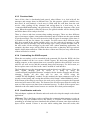
2 BACKGROUND
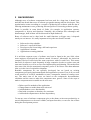
Although reuse of software components has been used for a long time, it hasn't been
until the last decade that reuse of software got popular among software developers. This
popularization comes according to a request of producing less software with the aim of
reducing maintenance costs, producing software quicker or increasing software quality.
Reuse is possible in some kinds of fields, for example, in application systems,
components or objects and functions. Naturally, this technique has advantages and
disadvantages, both of them will be discussed in depth further on.
Reuse of software can be done both for small functions or bigger ones; it depends
mostly on our interest. It is really important to keep the next factors in mind:
•
•
•
•
•
Software develop schedule
Software’s expected lifetime
Developer team’s knowledge, skill and experience
Application’s domain
Application executing platform
It is said that corporate reuse of software was born in Japan in the year 1984, when
some engineers developed the software named Cusamoto. Afterwards, the American
company Hewlett Packard tried the same experience with Gris and Proto. This means
that reuse of software is used frequently in huge companies in order to reduce costs and
earn more benefits, as well as to save time implementing and planning. This method has
also some risks, but the mentioned companies prefer to face these risks than unknown
risks, as in the case of original development.
Reusable components are not specially developed, but are based on existing
components previously implemented and used application systems. First of all, we need
to ask ourselves if it will be worthwhile to reuse a component, instead of creating a new
one. The main costs of the reuse are based on the component's documentation,
validation and the costs to make this component more generic. Some of the steps to
make a component more reusable are the next ones:
•
•
•
•
•
Delete specific methods of the application
Change names to make them more universal
Add methods to cover functionality
Deal with exceptions so that they are consistent
Add needed components to decrease dependency
To sum up, reuse of software components give us the chance to increase productivity as
reused components use to be more reliable, and apart from this, we can save lots of time
during the development process.
9
On the other hand, making a component to be reusable is not as easy as it seems, due to
the fact that we need to create generic interfaces for these components. At this point, we
should think about looking for a harmony between reuse and create.
The next subchapters describe the two operative systems related to this project (iOS and
Android). In the first subchapter, the design of a sample application in Android is
explained. This application was developed using Eclipse and the Android SDK. The
next chapter makes a comparison between Android and iOS and its respective sales and
market. Afterwards, a brief description of how to develop an iOS graphical interface is
presented. The advantages and disadvantages of using Android’s developing tools are
also defined. Apart from the user interface, a general description of sockets is also
detailed. Finally, some differences between iOS and Android are explained, focusing on
the IDEs (Eclipse, Xcode) and the programming languages (Java, Objective-C) used to
develop applications for both operative systems.
2.1 Android
Android applications are developed in Java. In the beginning of the project, we started
developing some trial applications in Android to see what we could do with the user
interface. To develop this trial application we used the Eclipse IDE, after installing the
ADT plugin for Eclipse. Apart from this, it is also needed to install the Android SDK,
and then, download the latest SDK tools and platforms using the SDK manager. There
is some interesting information about this in the Pro Android Apps Performing
Optimization book (Hervé Guihot, 2012).
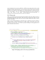
Now we are ready to create an Android app with Eclipse by clicking on “New Android
Application”. A manifest file will then be created describing the fundamental
characteristics of the app and defining each of its components. Figure 2 shows the
appearance of a manifest file (XML format)
Figure 2 AndroidManifest.xml file
The <uses-sdk> element declares the app compatibility with different Android versions.
When running the project an empty window will appear in the simulator’s or device’s
screen. From now on, the different activities (screens) will be declared in this file and
each activity will have a class where the developer can declare all the elements that will
appear in that screen.
There are two ways to run the app. The first one is using an Android simulator in the
PC. The SDK includes an Android Virtual Device Manager which gives the developer
the chance to create a virtual machine in a few steps. Once the virtual machine is
configured, the application is launched by clicking on the “run” button and selecting
“Android application”.
10
The second one is using a real Android device. For this, it is just necessary to plug in the
device to the development machine and install the appropriate drivers to enable the USB
debugging. The running process is the same as with the simulator.
The main aim of our trial application was to see how we could create a link between
two screens. We started creating a screen with a “Hello World” message and a button
that would send the user to the second screen. To make this, a hierarchy with
ViewGroup objects is defined. View objects are usually widgets including labels or
buttons. When a new application is created and a BlankActivity template is chosen, the
system creates automatically a RelativeLayout root view and a TextView child view.
In the root view, we add a label with the text “Hello World” and a button with the text
“send”. This button will have a call to a method using the “onClick” method of the
element. This method will be defined as a Java method in the MainActivity class. After
this, we can start implementing the method that will be used as a linker between both
activities. First, we need to create an “intent” class. “Intent” is an object that provides
runtime binding between separate components (such as two activities). To make the call
to the second activity, we will make it this way: “startActivity(intent)”.
The next step is to create a Java class which extends an “activity”. There is a predefined
method where it is possible to customize the appearance of the new screen such us
“onCreate” method.
Finally, in the AndroidManifest.xml file the new activity is declared as the Figure 3
shows.
Figure 3 Adding a new activity
Every activity is invoked by a previously created “intent”. This class will have a list of
attributes that could be strings, numbers, etc. When the new view is loaded, the view
can read these attributes using the method “getIntent()”. In other words, this is the way
to pass attributes from one view to another one.
11
As a result, we managed to create a “Hello World” sample application formed by two
views linked by a button. We have also passed the text appearing in the root view’s
label to the second view and write it in another label.
2.2 IOS: first steps
iOS was created by Apple in 2007 for the iPhone and iPod Touch. It can't be used under
non-Apple hardware, so development must be made with Apple hardware. As of
September of 2012, Apple's App Store contained more than 700.000 applications (from
now on, apps), which have been downloaded more than 30 billion times. It is said that it
is the second most used operative system for mobile devices, just behind Google
Android with a 14,9% share. Its interface is based on tactile interaction, using slices,
switches or buttons. iOS derives from Mac OS X, which derives at the same time from
Darwin BSD, based at the same time on Unix. Actual version (iOS 6.0) needs
approximately 770 megabytes of free memory in the device for running.
iOS was released officially on June 29, 2007. iPhone was created first of all, and some
months later iPod Touch was released. On January 27, 2010 iPad was released and by
April 2010, more than 185.000 apps were available for iOS in the App Store. iOS 6, (the
app developed in this project is running on this operative system) was presented on 12
September 2012, and it is the newest operative system in the family as of today.
One of the biggest improvements of iOS has been multitasking support. It is available
on iOS 4.0 and newer versions. This is a really important fact when working with
sockets, as connections must be opened at any time, even when the app is running in
background. Unfortunately, Apple accepts only the next API's: audio in the background,
VoIP, location in the background, push notifications, local notifications, task
completion, and quick change of applications. If no features related to any of these
API’s are included in the application, Apple will not let our app to keep our tasks alive
in background mode. In other words, our app will go to a suspension state.
iOS does not support Adobe Flash nor Java, as they are no secure and use too much
battery in Steve Jobs' opinion. On the other hand, iOS uses HTML5. The operative
system gives the user the chance to install a Jailbreak, which is used for installing
software non-supported by Apple. This software is not available in the App Store.
Installing this "patch" is completely legal, but invalidates the warranty of the device.
The programming language used for software developing is called Objective-C, which
is similar to C, but more orientated to objects. The operative system also has a
development kit, which can be used in Xcode, an IDE integrated in MAC OS X. iOS has
four abstraction layers: the Core OS layer, the Core Services layer, the Media layer, and
the Cocoa Touch layer, which will be explained later on.
Android and iOS are the most popular operative systems for mobile devices in the
world. iOS has a share of 14,9%, while Android has the 75%. iOS is developed by
Apple, and the company is responsible of manufacturing their products. However,
Google (Android's developer), doesn't produce its devices, Samsung, LG, and other
companies do it for them. This means that Apple gets more money for each device they
sell, approximately a 30:1 rate (10$ for Google, 300$ for Apple). Apart from that, only
12
33% of apps in the Apple's App Store are free, whereas the percentage in Android is of
64%. In summary, Android sells more devices due to their low prices, while Apple gets
more benefits for each device they sell.
In this context, Google decided to create j2ObjC. This is a tool used to translate code
from Android apps (Java code) to Objective-C, with the aim of reusing components. It
is complex to understand why Google would like to implement this kind of tool, but
there may be some reasons. One of them could be to try to get developers to write apps
for Android first. Many people think that it is easier to write Java code as it is more
popular, than to write in Objective-C which is a newer language. This way, Google
gives iOS developers the chance to write in Java first, and make them easier to start
developing their app, as many of them are not familiar to Objective-C. At the same
time, it will be a good opportunity for them to develop an Android app.
2.3 IOS: User I/F
At the beginning of the project we thought that the best way to satisfy the app’s user
would be to develop a universal app. This means that the same application could be
used in both an iPhone and an iPad. We started working on that idea the first days, but
we realised that it would be confusing to work that way, especially due to the difference
between iPhone’s icons and iPad’s icons resolutions. Apart from that, we did not have
all the icons available at first, as they were designed in other department, so we decided
to focus on iPhone’s GUI first.
Although, we did not have a sample app in Android for a Smartphone (we just had a
sample app for a tablet), we had some PDFs explaining the application’s main utilities.
These documents were enough for us to help us understand the appearance and the main
functionality of the app. Some of these documents showed us the different views of the
app and their relationship. Others mentioned the different functionalities of each button,
text field, table view, etc. The objective of the app we needed to develop was to make
the user understand easily the functionalities of the application and try to simplify as
much as we could the user’s experience.
The app needed to support different interface orientations, so that when the user spins
the device, the display spins in the same direction. We decided to support three
orientations (portrait, landscape left and landscape right). At first, we thought this will
be an easy task, but, then, we saw that it would not be so easy, as we needed to
customize programmatically all the orientation changes.
The status bar would be always shown during application launch. This way, user can
check internet connectivity and battery status every moment, a fact that will be very
important in our app.
The first screen would be an authentication screen, where user would need to enter a
“pin” number. After this, the system would check for the users’ list in the web service
and depending on the user who is trying to authenticate, the system will check if the pin
written by the user is the correct one. Afterwards, system would display a welcome
message and main screen would be displayed.
13
The main screen would contain a tab bar. The tab bar would have three tab bar items
(“scenes”, “manual control”, and “messages”). Each of them would have different
options. The first one would give the user the chance to change their location (home,
away, night or travel). The user would also be able to check the status of the appliances
for each location. The second one would be used to switch on or switch off different
devices and appliances at home. Finally, the third tab would contain the different
messages received from the server. Messages will be divided in five groups (“alarms”,
“alerts”, “notifications”, “pictures”, and “all the messages”). This display lets the user
see the different messages in detail just by clicking on the element of the list he/she
wants to check, apart from sharing the notification with other devices.
When a notification comes from the server, a pop-up would be displayed, even if the
application is in the background mode. This notification would stay on display until the
user clicks on it. The user would need to slide a bar to unlock the display and see the
notification details. Pressing the “OK” button will dismiss the pop-up and the new
notification would be added to the proper group in messages tab as a new message.
While the pop-up is being shown, the user would be able to choose if he/she wants to
send a message, or call someone. He/she would also have the chance to ask the server
for pictures taken by different cameras located in the house, and share them if needed.
Finally, user would make all these requests asynchronously. This means that user would
be able to make different things such as change scene, change device status, or look at
received messages, while system is dealing with a previous request. When the request is
finished (does not matter correctly or if an error occurred), a pop-up would be showed
whatever the user is doing.
2.4 IOS: sockets
Many iOS apps use HTTP protocols to communicate to a web server, as it is easy to
implement the connection and it is, at the same time, well-supported. However, in some
cases it is necessary to go a bit lower in the TCP/IP architecture, and communicate
using TCP sockets to a specific server. These are some of the advantages of using
sockets on iOS:
• It is possible to send just the data needed
• Server can always send data to connected clients
• Socket servers can be written in any language and without a dependency with a
web server
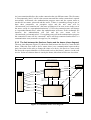
A socket is a tool that allows to transfer data in a bidirectional way. It is used to
exchange data between two different machines (it can also be used to exchange data in
the same machine) which are identified by an IP address and a port number. Figure 4
gives a graphical description of a socket communication.
14
Figure 4 Graphical description of a socket connection
Both machines must also define a transport protocol (TCP, UDP, etc). Sockets are
usually server-client based connections. When a server is listening and a client wants to
pass or receive data to/from it, a connection is opened. This connection is called socket
and it has a unique integer number, which will be the socket identifier. The same
process repeats with any other number of clients. The connection is only closed when
the client decides to close it, or when the server gets stopped.
There are different types of sockets:
• Datagram sockets (they use User Datagram Protocol)
• Stream sockets (they use Transmission Control Protocol or Stream Control
Transmission Protocol)
• Raw sockets (the transport layer is bypassed, and the packet headers are
accessible to the application)
The type used in our application will be the TCP-based client. Implementation will be
explained in another chapter. Many libraries are available in iOS, so all the different
types of sockets can be implemented.
There are many websites that explain how to create and use socket connections, but one
of the most comprehensive is the Ray Wenderlich site (Razeware LLC. 2012).
2.5 IOS: learned experiences for developers
Accessibility is one of the weakest points in iOS. It is necessary to have a Mac (iMac,
MacBook, etc.) for programming iOS applications. In addition, the developer will need
to keep his/her computer always updated with the latest version of Mac OS X.
Otherwise, he/she will need to pay to have the latest version of Xcode and then, the
chance to develop for the latest SDKs. On the other hand, Android developers will use
IDEs like Eclipse or NetBeans to create an app. These IDEs (and Android’s SDK) can
be installed in Mac, Linux or Windows.
The main difference between both operative systems is the programming language used
for developing apps. While Objective-C is used to develop an iOS app, Java is used in
Android. It is known that Java is a more popular language than Objective-C. For this
reason, Java community is bigger and there is much more documentation for Java.
However, both of them are based on C, so they have some similarities like primitive
15
types. So we could say that Objective-C has its advantages, but, Java has more cultural
and practical advantages.
After iOS 5.0, Apple created the Automatic Reference Counting. This tool makes the
compiler use the memory administration system during the compilation of the app. This
means that developers will need to write less code with the same performance. Besides,
developers will always have the choice to manage memory leaks manually if any errors
occur.
Interface design and development is easier with Xcode than with Eclipse. The main
advantage of Eclipse is that it can be used in almost any operative system (Linux, MAC
OS X or Windows), and it gives us the chance to program in many different languages,
such as Java, Ada, C, C++ or Perl. Nevertheless, it is necessary to install different
plugins to be able to program in each language as long as you are not developing in C or
Java. This fact makes Eclipse perform slower than Xcode. View controllers are also
more intuitive and faster in Xcode (particularly, after storyboards were available). There
are many different samples of view controllers in Xcode (standard view controller, table
view controller, navigation controller, tab bar controller, etc) while Eclipse just has a
standard one, so the most part of the view design must be done programmatically.
Both Android and iOS have their simulators. From my point of view, iOS simulator is
faster than Android one. However, Android simulator allows changing the hardware
details, such as the amount of RAM memory of the device, while iOS simulator uses the
resources of the PC. It is interesting to simulate an Android device with its natural
resources, but sometimes its performance can be annoying, so we must be careful with
the specifications we set in the simulator when running an app.
2.6 Review of related documents
This chapter shows the different information sources used during the project and a brief
description of each source.
Books
Guihot, Hervé. “Pro Android Apps Performance Optimization” –Apress
This book shows us how to optimize the performance of Android applications. For this
purpose, different algorithms are compared. The book is not only focused on
algorithms, but also on different user interfaces and socket connections. It is an
interesting book for an advanced Android developer, as it is necessary to have some
Java skills to understand some of the techniques explained.
Mac Programadores. "El lenguaje Objective-c para programadores C++ y Java"
It is a quite interesting book to create different user interfaces. The book puts special
attention in the programming language (Objective-C) to design stylish applications. It
starts explaining some basic code pieces in Objective-C, and then, explains how to
implement user interfaces programmatically. The book also talks briefly about internet
connections.
16
Watters, Blake."Introduction to RestKit"
It is a book that helps us understand the RestKit framework. This framework is not easy
to implement for beginners, so it is a very useful tutorial.
Websites
Apple Inc. (2012)
iOS Developer Library
http://developer.apple.com/library/ios/navigation/
It is the official help website for application developers. There are many different
articles here, such as tutorials for uploading an app to the App Store, characteristics of
iOS 6.0, or Objective-C tutorials. There are up to 1690 articles in this website to this
day.
Arizona Board of Regent (2003-2010)
The University of Arizona
http://math.arizona.edu/support/account/remoteshell/putty.html
This website explains the steps to use Putty, a tool used to make connections via SSH.
Awesome Inc. template (2013)
Deusty
http://www.deusty.blogspot.com.es/2010/05/introducing-cocoa-lumberjack.html
This blog explains how to use the Cocoa Lumberjack framework in Xcode. It does not
explain how the framework works, but the steps to follow to make it run.
Cortex IT Ltd (2013)
Convert String
http://www.convertstring.com/Hash/SHA256
This web tool returns the SHA256 code from an input text. It returns 64 hexadecimal
characters in the text field above.
Google Inc. (2013)
Google Projects
http://code.google.com/p/wsdl2objc/wiki/UsageInstructions
It gives some explanations about how to use the wsdl2ObjC tool. This tool created by
Google, offers this blog to resolve doubts, show tutorials, or help users installing the
tool.
17
Google Inc. (2013)
Google Projects
http://www.code.google.com/p/j2objc/
It is the official website for the j2ObjC tool, created by Google. From here, the tool can
be downloaded and some tutorials can be checked. There are also installation guides,
forums, etc.
IBM (2013)
http://www.ibm.com/developerworks/webservices/tutorials/ws-eclipsejavase1/chapter5.html
This is a tutorial to create a standalone web service based application. This web service
is executed with Eclipse, and it helps us to test the server and to export the WSDL file.
iPhone4Spain (2011)
iPhone4Spain
http://www.iphone4spain.com/tag/curso-programacion-ios-aplicaciones-iphone-ipad/
It is an ideal tutorial for beginners in iOS. It shows how to use Xcode, how to create
views and make links between them, how to design tables, etc. It also offers some
exercises to practise.
iPhone Dev Sdk (2013)
http://www.iphonedevsdk.com/forum/
In this forum, how to port an application from iPhone to iPad is discussed. It is very
useful as it helps us to do the porting in a few steps.
iPhone SDK Articles (2011)
http://www.iphonesdkarticles.com/
There are some useful tricks related to Objective-C in this website. There are also some
advices about graphical interfaces design and it shows how to create from scratch views
and tables. There are some screenshots to help the reader in an intuitive way and also
lots of code lines, so that the user learns quickly the tricks of graphical interfaces in iOS.
Lamarche, Jeff (2013)
iPhone Development
http://www.iphonedevelopment.blogspot.com.es
Jeff Lamarche shows some tricks for graphical interfaces in his blog. He puts special
attention in the dialogs, as it is not easy to customize them.
18
Razeware LLC (2012)
Ray Wenderlich: Tutorials
http://www.raywenderlich.com
for
iPhone/iOS
Developers
and
Gamers
This website offers all kinds of tutorials. Graphical interfaces, socket connections,
simple applications, games, etc.
Refsnes Data (1999-2013)
W3 Schools
http://www.w3schools.com/webservices/default.asp
It gives general information about web services; how to implement them, how to call
them. Apart from this, there are some examples of web services to test some of them
with our browser.
Rose India (2013)
http://www.roseindia.net/tutorial/iphone/examples/index.html
There are some steps to write the code in a simple way in order to take less time to
develop and application in this site. There are some code samples to directly copy and
paste. This code can be related to dialogs, buttons with text, sample applications,
validating text fields. There is a section for each of them, and there is a deep
explanation of how to use each code piece.
Schwartz, Alex (2012)
GT Productions
http://gtproductions.net/blog/ways-to-get-rejected-by-apple-app-store-tips/
This blog explains the steps to follow in our application to prevent it from being
rejected in the App Store. There is some advice that can result really useful as it needs
some time from uploading the application until an answer from Apple is received.
Youtube, LLC (2013)
Youtube
https://www.youtube.com
This popular site has been used to look for interesting iOS tutorials. Most of the tutorials
are in English.
19
20
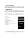
3 PROTOTYPE: IOS USER I/F
Before starting with the development of the mSecurity application we started creating
simple applications to start dealing with graphical interfaces. One of those applications
is described in this chapter. A general view of how to manage a project in Xcode is
described in Appendix I (basic Objective-C experiences).
3.1 Sample application
This application is a “tab bar” based application. It has two tab bar items. The first tab
bar has two views in its hierarchy and the second tab bar has three views. The concepts
in which we put special attention were the management of a tab bar, the transition
between different views, the use of sliders, the use of a variable in different screens, and
the use of table views. This application does not have a useful functionality for the user.
The first screen of the application shows a view with a navigation controller in the top
of the screen and a button. Figure 5 shows us the appearance of the first screen in the
iPhone simulator and the implementation file of the view controller.
Figure 5 First view controller (implementation file and simulator screenshot)
This screen gives the user a couple of options. If the user presses the “ahead” button a
new screen will be opened with the “Ahead” message. However, if the user presses the
“Hello World” button, the new screen will show a “Hello World” message. This is
achieved by using the “setString” method which is called when any of the buttons are
21
pressed. The input parameter is saved in the local variable of the new screen and the
new value is used as the text in the new screen’s label. The transition is made by using
the method “pushViewController” as shown in figure 5. Figure 6 shows the second
screen after clicking on the “ahead” button of the navigation bar.
Figure 6 “Ahead” message
The first screen in the second tab has a similar appearance as the first screen in the first
tab. If the user presses the “ahead” button, now a slider will appear in the new screen. If
the slider’s thumb is moved completely to the right, the application will go to the next
screen. This screen will be a table view. The data in this table view will be loaded
programmatically. Figure 7 shows the code needed to add data to a table using the Table
View Controller template.
Figure 7 Table View Implementation
22
In this case, each cell of the table will have a title and a subtitle. The title of the row will
be the number of the row using the row attribute of the indexPath. The subtitle will also
contain the number of the row but it will be preceded by a text (“Subtitle:”). In the
methods above the number of sections and the number of rows for each section are
defined, in this case, five rows for one section. The table will have a navigation bar
inherited from the previous screen which is defined in the right-side of the project
screen in Xcode as seen in Figure 8. The navigation bar is listed as “Top Bar”. In this
case, all the attributes are inherited (inferred) from the previous screen.
Figure 8 View Controller’s attributes
Finally, Figure 9 shows the main storyboard for this project. For a proper transition
between screens we used a navigation controller for each tab bar (this technique is also
used in the mSecurity application). There are not arrows linking the different views as
all the transitions have been made programmatically using the “pushViewController”
that was mentioned above in this chapter.
Figure 9 Application’s main storyboard
23
24
4 PROTOTYPE: IOS COMMUNICATIONS
This chapter describes the application we designed as a beta application to test a serverclient communication using the SOAP protocol. The first two sub points give some
information about two popular protocols for exchanging information (SOAP and
REST). The third one deals with the application.
4.1 REST Protocol
Representational State Transfer is a style of software architecture for distributed
systems such as the World Wide Web. There are six constraints in its architecture which
are the next ones: client-server, stateless, cacheable, layered system, code on demand
and uniform interface.
REST generally runs over HTTP so it uses HTTP operations (GET, POST, PUT, and
DELETE) and involves reading a web page that contains an XML file. REST is often
used in mobile applications, social networking Web sites, mash up tools and automated
business processes.
REST is an “architectural style” that takes advantage of the existing technology and
protocols in the web, including HTTP and XML. REST is easier to use than SOAP
(Simple Object Access Protocol), which requires writing or using a provided server
program (to serve data) and a client program (to request data).
Some interesting facts about REST protocol are discussed in the Introduction to Reskit
book by (Watters, 2011).
4.2 SOAP Protocol
SOAP is a protocol specification for exchanging structured information in the
implementation of web services. It relies on XML Information Set for its message
format and in other layers such as HTTP or SMTP (Simple Mail Transfer Protocol) for
message negotiation and transmission.
The SOAP processing model describes a distributed processing model. This model
contains the following nodes:
SOAP sender: A SOAP node that transmits a SOAP message.
SOAP receiver: A SOAP node that accepts a SOAP message.
SOAP message path: The set of SOAP nodes through which a single SOAP message
passes.
Initial SOAP sender (Originator): The SOAP sender that originates a SOAP message
at the starting point of a SOAP message path.
SOAP intermediary: A SOAP intermediary is both a SOAP receiver and a SOAP
sender and is targetable from within a SOAP message. It processes the SOAP header
25
blocks targeted at it and acts to forward a SOAP message towards an ultimate SOAP
receiver.
Ultimate SOAP receiver: The SOAP receiver that is a final destination of a SOAP
message. It is responsible for processing the contents of the SOAP body and any SOAP
header blocks targeted at it. In some circumstances, a SOAP message might not reach
an ultimate SOAP receiver, for example because of a problem at a SOAP intermediary.
An ultimate SOAP receiver cannot also be a SOAP intermediary for the same SOAP
message.
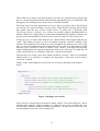
This is an example of a SOAP message for the “getMensajes” method:
<?xml version="1.0"?>
<soap:Envelope xmlns:soap="http://www.w3.org/2003/05/soap-envelope">
<soap:Header>
</soap:Header>
<soap:Body>
<m:GetMensajes
xmlns:m="217.126.198.179:8080/SrvSecurityRemotoHogar/servicioAccesoRem
otoHogarService?wsdl">
<m:alarma>id=M_1201</m:alarma>
</m:GetMensajes>
</soap:Body>
</soap:Envelope>
Interesting information about SOAP services is available in the iPhone Dev Sdk (2013)
and iPhone SDK Articles (2011) websites.
4.3 Sample application (calculator)
We decided that it was more interesting to implement a SOAP based server-client
architecture for our application. To make a trial with it we created a simple calculator
that would send some data to a server and this server would have some methods (sum
and subtract) that would give an answer depending on the input numbers.
The first thing was to create a user interface for the calculator. There are two labels and
an operator button. There is another button to change the operator sign. When the user
writes the two numbers and presses the operator’s button, the application sends a
request (SOAP message) to the web service, and when the web service answers with
another SOAP message, then, all the data is parsed and the number is showed in a third
label.
The web service contains a WSDL file with all the operators defined on it.
The next points explain the process to parse data from the WSDL file, in other words,
the process to translate an XML document into a string.
26
Figure 10 Screenshot of the sample application
Figure 10 shows us a screenshot of the developed calculator. The “off” button is used to
change between the sum and the subtraction. When clicking on this button the sign
between the two digits will change. The result will be visible in the text area next to
“Resultado:”. When clicking on “Calcular”, the request will be sent to the web service
within a SOAP message, and the web service will return an answer. Figure 11 shows the
request SOAP message sent by the application to the web service and the web service’s
response.
Figure 11 SOAP request and response messages
In this case, the web service returns an error message because the server was off by the
time the screenshot was taken.
27
4.3.1 Using wsdl2objc to export code from a wsdl
wsdl2ObjC is an open source tool created in 2008 by a group of American developers to
translate in an easy way a WSDL into Objective-C code. Three versions have been
released since it was created (0.4, 0.5 and 0.6). The one used for this project has been
0.6 which includes fixes for iPhone compatibility and a greatly improved WSDL
compatibility.
Interesting information related to exporting data from a WSDL using the mentioned tool
is available in the blog created by Google Inc. (2013) for this tool.
A WSDL is a document in XML format which is used to describe web services. A WSDL
describes the public interface of a web service. A WSDL is often used in combination
with SOAP and XML Schema. A client can see in the WSDL file of a web service the
available functions of it, and can use SOAP to make a call to one of these functions.
Special data types are included in a XML Schema format in the WSDL file.
The structure of a common WSDL is described by the following elements:
-Data Type: This chapter defines the data type used in the messages (XML format).
-Messages: The elements of each message are defined here. Each message can have
many logic parts.
-Port types: In this chapter the allowed operations and the exchanged messages in the
service are defined.
-Bindings: Used communication protocols are defined.
-Services: Group of ports and their respective addresses are defined. The previous
chapters may be referenced here.
A WSDL example:
<definitions name="HelloService"
targetNamespace="http://www.examples.com/wsdl/HelloService.wsdl"
xmlns="http://schemas.xmlsoap.org/wsdl/"
xmlns:soap="http://schemas.xmlsoap.org/wsdl/soap/"
xmlns:tns="http://www.examples.com/wsdl/HelloService.wsdl"
xmlns:xsd="http://www.w3.org/2001/XMLSchema">
<message name="SayHelloRequest">
<part name="firstName" type="xsd:string"/>
</message>
<message name="SayHelloResponse">
<part name="greeting" type="xsd:string"/>
</message>
<portType name="Hello_PortType">
<operation name="sayHello">
<input message="tns:SayHelloRequest"/>
<output message="tns:SayHelloResponse"/>
</operation>
</portType>
<binding name="Hello_Binding" type="tns:Hello_PortType">
28
<soap:binding style="rpc"
transport="http://schemas.xmlsoap.org/soap/http"/>
<operation name="sayHello">
<soap:operation soapAction="sayHello"/>
<input>
<soap:body
encodingStyle="http://schemas.xmlsoap.org/soap/encoding/"
namespace="urn:examples:helloservice"
use="encoded"/>
</input>
<output>
<soap:body
encodingStyle="http://schemas.xmlsoap.org/soap/encoding/"
namespace="urn:examples:helloservice"
use="encoded"/>
</output>
</operation>
</binding>
<service name="Hello_Service">
<documentation>WSDL File for HelloService</documentation>
<port binding="tns:Hello_Binding" name="Hello_Port">
<soap:address
location="http://www.examples.com/SayHello/">
</port>
</service>
</definitions>
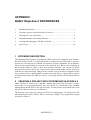
Once we are familiarized with WSDLs, usage of wsdl2ObjC will be explained. First of
all, we need to download the necessary files that can be found in the official website in
the downloads section. After downloading the files, we launch the application and paste
the URL of the WSDL that we want to translate in the upper text field. In the second text
field, the destination folder will be defined. The created files will be added to this
directory after clicking on “parse WSDL”. There will be one .m/.h file for each
namespace in the source document.
The next step is to add the generated files to Xcode. Each project that uses the generated
web service code will need to link against libxml2 by performing the following for each
target in the Xcode project:
1. Get info on the target and go to the build tab
2. Add "-lxml2" to the Other Linker Flags property
3. Add "-I/usr/include/libxml2" to the Other C Flags property
It is also necessary to add the CFNetwork.framework to build an iPhone project.
29
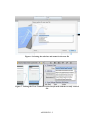
Figure 12 Using a web service
Figure 12 shows us how to use a generated method. It is necessary to import the main
class from the ones generated with wsdl2ObjC. Then, an instance of the binding is
created and space is allocated for the needed method. The next step is to define the input
parameters of the method before using it. Once all the needed parameters are loaded the
call to the method is made. The treatment of the received answer (including data
parsing) will be explained later on.
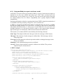
4.3.2 Parsing the wsdl
wsdl2ObjC uses the NSDATE+ISO8601Parsing class to parse the received data from
the WSDL. This class is a little bit ambiguous. In order to parse the data we decided to
use the official Apple’s parser. This class is called NSXMLParser. Although it is not one
of the fastest parsers available in the internet, it was good enough for our needs and
being the Apple’s official one would be a big advantage as there is a lot of
documentation in the iOS Dev Center.
The first step to use this parser was obviously to delete all the code related with the
parser that came by default in the “connectionDidFinishLoading” method of the main
generated file. All this code was replaced by the next two code lines.
An instance of the parser is initialized with the information stored in the responseData
variable which was previously read in the “didReceiveData” method. Then, as usual, the
current class’ delegate is set.
Apart from creating an instance of the parser, it is also necessary to read all the elements
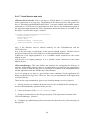
in the message received from the web service. For that purpose, the method
“didStartElement” was used.
The web service returns a different element name depending on the user’s request. If the
user wants to see the messages list the element’s name will be “alarma”. If he/she wants
to check for the devices’ status, the web service will return “estadoDispositivos” and the
30
same will happen for each request. As a result, each method will compare a different
string for the current element name. The current element will have some attributes that
will be read by using the “objectForKey:string” method of the NSDictionary class.
These attributes will be saved and a new element will be created using them. This new
element will be an object that can be a message, a device, etc. The classes for these
objects must be previously defined in the project.
Figure 13 and Figure 14 show the implementation of the “didStartElement” method for
the “getMensajes” request and the SOAP response represented in the web service. The
reserved word for the messages type is “alarma” so just those elements are going to be
treated.
Figure 13 “getMensajes” SOAP response
Figure 14 “didStartElement” for “getMensajes” request
31
4.3.3 Received data
Once all the data is downloaded and parsed, what follows is to deal with all the
messages and arrange them in different lists. For this purpose, global variables have
been used. In each method, a local array is filled with the read data from the web
service. After reading all the elements and saving them in a local array, in the
“connectionDidFinishLoading” the global array is filled with the elements of the local
array. When the method is called by the user, the global variable will be already filled
and all the data will be ready to be used.
There is a fact to take into account when reading messages. There are three different
types of messages (alarms, alerts and notifications) and all of them use the same method
to get the messages. The user will not need to load all types of messages all the time; it
is possible to ask just for alarms, for example. For this reason, three different arrays
have been created in the global variables store, one for each type of message, so after
loading one kind of message, only that message type’s array is filled and later read. If
the user needs all the messages at the same time (when launching application, for
example), the three arrays will be filled in the next order so that they don’t get mixed:
alarms, notifications and alerts. When the three of them are filled, an array with the sum
of them will also be created.
4.3.4 Customizing the SOAP request
When the user makes a call to a method in the generated file from the WSDL, the first
thing the method will do is to create a SOAP request. We had some problems when
sending requests, as the requests that were created by default with wsdl2ObjC were not
valid for our web service and this returned always null messages. For this reason, we
had to replace some code lines in the “main” method of each interface.
The first thing is to get the input parameters and put them in an NSDictionary. Then, the
entire SOAP message will be saved in a string by using the
“serializedFormUsingHeaderElements” method with the header elements and the body
elements. Finally, all this data will be sent via HTTP using the
“sendHTTPCallUsingBody” method. For this method, the input parameters will be the
recently created string and a string that will have this format: “nameOfMethod_action”.
If the format of the string is not correct, the web service will not recognise the requested
action and will return a null value. The format of the SOAP request must be exactly the
same as if the request was done from an internet browser. To check if the requests were
identical to the ones made from a browser we used the Wireshark packet-analyzer.
4.3.5 Used libraries and tools
This subchapter explains the libraries and tools used to develop the sample socket-based
application.
NSStream: This is the library used to read from the communication manager or write on
it. In every loop the method read of this library is executed. If the house answered
something or an alarm has been simulated, this method will return some bytes and these
bytes will be treated. If there is an error while reading data from the socket, this
32
function will return -1. In this case, an exception will be thrown and this data will not be
evaluated.
Wireshark: This open-source packet analyzer is used for network troubleshooting,
analysis, software and communications protocol development, and education. We used
the tool in order to see where and why the synchronization in the socket connection was
lost. It was also used to see if the user’s requests were made in the proper format.
This information has been taken from the Wikipedia.org (2013) website.
33
34
5 MSECURITY IOS APPLICATION
In the fifth chapter the final application is described. The application’s name is
mSecurity. There are some subchapters inside the fifth chapter. The first one describes
the application requirements. The second one talks about the user interface. In this
section the main problems during the user interface design and some specific features
for this project are explained. In the fourth section, the implementation of the socket
connections is described. In the middle, the architecture of the whole application is
explained. There are some screen captures showing the design of the different screens in
the application and some class diagrams defining all the communications between the
device, the Services Centre and the house.
5.1 Application requirements
mSecurity is a socket-based application. It will be used to protect the users home even
when the user is away. For that, user will be able to choose between four scenes (home,
away, night and holiday). In each scene, the sensors in the house will have a different
status. A table with the list of items’ status can be seen by touching the scene icon. For
example, if the user is away, the movement detector will be on and will send an alarm if
someone is getting into the house. If the user is at home, the detector will be off, and
alarms will not be sent.
User will also be able to change the status of a device in any of the four scenes. These
orders will be sent to the server and the server will change the status of the devices.
When the order is executed, the server should return a notification to the mobile device
notifying if the action has been finished successfully or not. Notifications will be
divided in three groups. Alarms, system alerts and notifications. When an alarm comes
to the device, a pop-up window will be raised, even if the app is in the background
mode. In this case, a universal pop-up will be raised first and then, if the “OK” button is
pressed the app will be “launched” with the pop-up view controller. If not, the first
notification will stay in the device’s notification pane. If several notifications come and
the user does not open any of them, the first one that will appear will be the oldest
notification.
User will be able to see all the messages received, divided in 5 groups (alarms, system
alerts, notifications, pictures, and all the messages). The last group will store all the
messages, but user will not be able to see each message’s details from here. On the
other hand, the rest of the groups will have a detail view controller to see each
message’s details by clicking on a cell. If a message is still not read, that message’s cell
will be darker. Once the detail’s view controller is opened, that selected cell in the table
will be brightened.
When an alarm comes to the device, a pop-up window will appear. This window will
show the user some details of the new alarm, such as the description, the time, or the
date. When user skips these view controllers, he/she will have the chance to send an email, make a phone call, or ask for some pictures. After the user makes the
acknowledgement by clicking on a couple of buttons, the app will go back to the
messages screen and the new alarm will appear in the alarms table view.
35
The app will always be active, obviously, except the first time that it is launched. For
the app’s first launch the app will load all the data from the web service, including
scenes, devices status or users’ information. User will need to authenticate by writing a
four-digit pin number in the login view controller. The valid pin number will come from
the web server. The web server will return a different number depending on the MAC
number of the mobile device, which will be registered in a database. If the MAC
number of the device is not registered, the pin will not be transmitted and login will not
be possible. Once the user has entered the valid pin number, the system will open the
socket connection and if authentication goes well and there is not a problem with the
connection, the scenes view controller will be shown. If a problem occurs, the app will
keep loading until socket connection is opened. If the application is executing and
internet connection is lost, app will keep connecting until the connection returns. At this
point, authentication process will be repeated. Appendix II provides a more detailed
description of the application resources.
5.2 User I/F
This chapter explains the solution to the different problems that appeared during the
development process related with the user interface design.
5.2.1 The autorotation problem
Xcode gives the developer the chance to use the “autoresize” tool, which is an
interesting tool to auto rotate basic elements, such as text areas, buttons or labels.
However, it is more complicated to rotate other elements like text fields or alert views
(frequently used in our app). This task must be done programmatically as an alert view
(for example) is not drawn in the storyboard, and it is probably one of the biggest
challenges in the project. There is a main method in iOS library that helped us manage
the autorotation in the different views, “willRotateToInterfaceOrientation”. In this
method, a variable is defined depending on the new rotation. Alert views are also taken
into account in this method, as it is not the same to treat a screen with or without an
alert view. If there is not an alert view in the screen we just set the value of the variable.
However, if there is an alert view on the screen and we rotate the display, it is necessary
to make some changes.
The first step is to dismiss the previous alert view to create a new one, so every time the
display is rotated, the current alert view will dismiss. Afterwards, the same alert view
must be created with the same style but with different size and position. For this reason,
we needed to check for the new screen position and then, call to an earlier created
method that would launch the new alert view. In this method, new alert view is
customized depending on the screen orientation. There might be more than one different
alert views, for example, the label is not necessary the same in all the alert views, so
more than one methods were used in some cases. To manage this, a global variable was
defined in the current class, so the text in the alert view became variable.
Besides alert views, text fields also needed to be implemented programmatically. The
same
steps
were
followed
to
implement
the
text
fields.
The
“viewWillRotateToInterfaceOrientation” function was used. Depending on the next
36
screen orientation, the text area would have a different size and position, and so as the
background image. Apart from this, it was necessary to check for the screen orientation
when the view is loaded. For this purpose, the “interfaceOrientation” attribute was used.
When this attribute’s value was UIInterfaceOrientationPortrait, the text field had a
value, and when it was either UIInterfaceOrientationLandscapeRight or
UIInterfaceOrientationLandscapeLeft, the value was different.
5.2.2 Phone calls
There are some libraries used to show the user the phone call screen. However, there is
an important fact to take into account. This is the Apple rejection risk. There are some
libraries that might be rejected. The one we used is a quite common one and it’s easy to
use (just a few lines).
There are some different numbers to call in this app, so when the user presses a button a
different number is called. Each button has its sender; Figure 15 shows the code to open
the phone call screen if the “CIC” button is pressed and Figure 16 the appearance of a
phone call made with an iPhone.
Figure 15 Designing a phone call screen programmatically
37
Figure 16 Making a call from an iPhone
5.2.3 E-mail
There is also a simple library to implement the e-mail
e mail screen. While the library for
phone calls is unofficial, this one is shown by Apple,, so we decided that it was the
easiest and comfortable option to develop the e-mail
e mail screen. There is a main function
called “didFinishWithResult” in the MFMailComposeViewController where four
different cases are taken into account: message cancelled, message
message saved, message sent,
and message failed. Each of them will return a string and depending on the string
returned the app will go to the previous or the next string. For example if the result is
“message sent” then, the app will show an alert view tellingg the user that the message
has been said. On the other hand, if there has been an error sending the message, the app
will show an alert view warning the user that something has gone wrong.
Anyway, before this step an instance of MFMailComposeViewController
MFMailComposeViewControlle must be
created as shown in Figure 18.
18. This is done when the user presses a button to send a
message. The library’s “canSendMail” function checks if the device is able to send
mails (for example, there is no network, or when using a simulator). If answer is yes,
then a new delegate is created and the body of the mail is filled (subject, CC, BCC, text)
depending on the data we got before opening the view. Data can be changed manually
before sending the message. After pressing the button the e-mail
e mail screen will
w be shown
(Figure 17).. The screen will have the same appearance that has the Mail application in
38
iOS. If the device cannot send an e-mail, an alert view will appear in instead of the new
view.
Figure 17 E-mail screen appearance
The sent e-mails will be saved in our mailbox in Mail. For sending e-mails it is
necessary to have our e-mail account properly configured in our device’s Mail app.
Otherwise, the presented tool will not work and the application will show us an alert
view telling us that the device is not ready to send messages.
Figure 18 Creating an instance of MFMailViewController
39
5.2.4 Porting from iPhone to iPad
Before starting with this task, I looked at some different tutorials for porting an app
from iPhone to iPad. The most repeated feature in those tutorials was the
“autoresizing” tool in Xcode, but as I explained before this is just useful for simple
elements. So the task resulted hard if we had to take into account all the little facts in the
iPhone app, most of them forgotten when the iPad app needed to be developed. The
main difference between both applications was the tab bar’s size (bigger in iPad).
As it was explained before, two main methods were used to manage the tab bar,
“showTabBar” and “hideTabBar” which are shown in Figure 19 and Figure 20. The
methods are the same for both devices; the only difference is the amount of pixels for
the tab bar in each device. The next figure shows us the difference between a method
for iPhone and a method for iPad.
Apart from this, alert views must also be treated, so these ones were treated the same
way as the tab bar. The only thing that changes is the resolution in the alert view
elements, for example, the text, the buttons, or the background image.
Figure 19 “hideTabBar” method for iPad
40
Figure 20 “hideTabBar” method for iPhone
5.2.5 Used libraries
Libraries in Objective-C are called frameworks. There are different frameworks for Mac
or for iOS. The frameworks used for user interface were the next ones: CoreGraphics,
Foundation, and UIKit. Each of them has some header files inside, which contain pieces
of code revised by Apple. These headers can be used wherever in the code just by
writing the name of the file before the method we want to use. For example, if we want
to use “UIAlertView.h”, we would use the next format [UIAlertView
nameOfTheMethod:parameters]; The most important framework for this phase of the
project has been UIKit, as it contains most of the headers for the graphical interface,
such as NSText, UIAlertView, UILabel or UITabBarController. Without them, nothing
would be able to implement and this is one of the main differences between Android
and iOS.
For this reason, it is not possible to port directly a Graphical User Interface based on
Android to iOS. While Android uses Java libraries, iOS uses Objective-C ones.
However, as we are going to see later, in the servers’ part, there are some libraries that
are portable from one operative system to the other one.
5.2.6 Using a singleton to manage global variables
The singleton pattern is a powerful way to share data between different classes and parts
of the code. Singleton classes exhibit a really useful design pattern. Many of the core
Apple classes follow this pattern, such as [UIApplication sharedApplication].
41
The singleton class must be initialized as an object and the first step is to create an
instance of it that will always be managed as a “single shared instance”. Once the
instance is created, we can make as much calls as we want to that instance’s methods
from every class.
This class has been used in this project to manage global variables. It is important to
design this class in a tidy way. Creating this class in a wrong way may cause little
memory leaks, and as the class is called frequently the result can be application
crashing. The next figures show how the singleton is initialized and used.
The interface is created as any other class. All the elements that will be used are defined
in Figure 21.
Figure 21 Variable Store definition
Each object in the singleton will have a “get” and a “set” function, so that there is a
chance to read or write a global variable all the time (Figure 22).
Figure 22 Setters and getters in the singleton
As usual in every class, it is necessary to synthesize all the elements (Figure 23).
42
Figure 23 Synthesizing the elements
Figure 24 shows how to use a singleton class. The first code line reads from a
previously created array (messages array) and the last line writes the number of existing
alerts in a global variable. The second line writes the output of the messages array in the
alert type messages array.
Figure 24 Reading and writing
5.3 Architecture
The architecture of this project is divided in three parts; the user’s device (iPhone/iPad),
the Services Centre and the house. The part of the architecture where we have been
working has been the connection between the device and the Services Centre, this
means that the link between the Services Centre and the house has been designed by
other departments.
5.3.1 User interface’s class diagrams (storyboard)
As I explained before, after the fourth version storyboards can be used in Xcode. It is a
simple way to create a link between a view controller created graphically and the code
created for it. Figures 25 to 32 show some parts of the storyboard in this project.
43
Figure 25 First Screens
Figure 25 shows us the design of the first screens. Navigation controller is completely
necessary to be able to push from one view to another programmatically. The arrow
before the navigation controller means that it is the first view controller. “Inicio View
Controller” and “Kargatzen View Controller” are empty because the activity indicator
view (loading) is created programmatically. “Login View Controller” contains 10
buttons for digits, one for rubbing the text field, and one to accept the introduced pin
number, and a button for retrying the connection in case something went wrong in the
previous attempt. Then, “Hola View Controller” will show a greeting message with the
name of the user.
Figure 26 shows the structure of the “Tab Bar Controller” with its respective three
navigation controllers, one for each tab. The name and the picture for the tab are defined
here, but can be changed programmatically if needed.
44
Figure 26 Tab Bar Controller
Figure 27 and Figure 28 show the structure of the three main screens (scenes, manual
control and messages). They are all child view controllers of the tab bar controller and
their respective navigation controller.
45
Figure 27 Scene, manual control and messages view controllers
Figure 28 Relationship between tab bar, navigation and view controllers
46
Inside the messages group, there are some different message types. For example, alarm
type messages. This is the structure of its table view and detail view controller, where
we can see that the “share” screen with its buttons is visible in the storyboard (just
visible when pressing “share” button in the app). As some facts have been customized
programmatically, there is a “custom” segue between them (Figure 29).
Figure 29 Alarma table view controller and alarma detail view controller
As mentioned before, the new alarm pop-up is not an alert view, but a simple view
controller. The next figure shows the design of the pop-up dialog. It has a navigation
controller in the beginning to make possible to navigate between screens. The label’s
values are written programmatically and so as the design of the “slide to unlock” as
shown in Figure 30.
Figure 30 New alarm dialog
47
In Figure 31 the scene change progress is visible. When pressing a scene icon a pop-up
will appear in a new window “Confirmacion Casa View”. If the user clicks the cancel
button the app will go back to the main screen. However, if the user presses the send
button the app will go to “Espera Casa View” and will wait until the socket gives an
answer (if it does). If the scene change has been successfully done, the next time the
user presses that scene’s button, in instead of a pop-up, a table will appear showing the
state of all the devices in that scene (devices’ state can be changed in control manual).
Figure 31 Scene change process
Although photos have still no interaction with the web service and have not a real
functionality, the user interface has been designed. The user receives some pictures
from the web service and has the chance to see the details of the pictures and send them
via e-mail. As in the rest of messages types, when user clicks on a table’s element the
details of that picture’s group will be shown (Figure 32).
48
Figure 32 Pictures management
5.3.2 Socket server’s class diagrams
The Services Centre is located in the 217.126.198.179 IP address. The Web Service that
will manage the devices’ status and the messages’ list is located in the port 8080. The
notification manager that will deal with the messages sent via socket is located in the
port 8888. When the user makes a request to get some information from the database or
wants to change the status of a device, he/she is making a call to the 8080 port. The
services centre will then answer with an order identifier.
If the request is a status change, the user will have to parse and save that identifier until
the same identifier comes from the notification manager confirming that the asked
request has been made. If there is no answer in a 30-second time the request is rejected.
If the user is asking the Services Centre for information about devices, messages or
whatever, the Services Centre will “display” all the information and the client will need
to parse all the data in that moment.
The Services Centre needs to be connected to the house associated to the user, so if
there is no connection between the house and the Services Centre, this will display the
last status of the house before losing the connection. If the user wants to set a new scene
49
or change a device’s status, the Services Centre will not send an identifier back to the
user, and the user will realise that there is no network connection between the Services
Centre and his/her house.
A class diagram is displayed in Figure 33 and Figure 34 shows the state machine of the
socket connection.
Figure 33 Relationship between the device and the services centre
Figure 34 State machine
50
As it was mentioned before, the socket connection has six different states. The first state
is “Desconectado_inicio” and it is the current state until the socket connection is opened
successfully. Afterwards, the authentication progress starts and the system starts to
encode the user name, password and the nonce. If there is something wrong in one of
these three parameters, an exception raises and the new state will be
“desconectado_errComunicacion” (the same will happen if an error occurs in the rest of
the states, except in “esperandoAutenticacion”). If not, the connection state will change
to “esperandoAutenticacion” where the authentication will start. If the credentials are
incorrect, the authentication will fail and the new status will be
“desconectado_errAutenticacion”. If everything went well in the authentication progress
the connection’s state will be “conectado” and it will keep connected unless there is a
communication error (network coverage loss, for example).
5.3.3 The link between the Services Centre and the house (class diagram)
The next class diagram (Figure 35) shows the link between the Services Centre and the
house. When the user reads a device status, there is no communication between these
parts, but when he/she asks to change the status of a device, the Services Centre sends
the house the request identifier via socket and receives the house’s answer via the web
service. In the case that an alarm is sent by the house, this alarm will be sent via socket.
deployment mSecurity
FagorCloud- CentralServi ci os (CS)
FagorCloud::Nodo_BD_Serv icios
«device»
Home1 :GlobalScale
Guruplug
Solicita info sobre orden
FagorCloud::Nodo_PublicadorWS
(from Infraestructura)
Comunica resul tado de ejecutar la orden recibida
Solici ta IP NMS
Infraestructura::
MacX HomeX :
Teléfono móv il
Android
Solicita Info Estado Hogar
Solicita Accion sobre Hogar
Envia orden al hogar
Home 1 se conecta
Soli ci ta envio de
notificaciones y
alarmas al usuario
móvil
Gestiona usuari os en NMS Solicita envio orden al hogar
Usuari o movil se conecta
CS notifica resultado envio accion al
hogar
FagorCloud::Nodo_MMS
CS notifica alarma disparada en el hogar
CS notifica resultado de la accion solictada en el hogar
HomeN se conecta
«device»
HomeN :GlobalScale
Guruplug
(from Infraestructura)
Figure 35 Communications class diagram
51
First of all, the houses are connected to the notification manager (NMS). Then, the user
launches the application and gets connected to the notification manager. The user then
has two options. The first one is to check the home status information. In this case, the
web service will return a SOAP message giving the answer to the requested method
(data will be read from the database). The second one will be to change the status of a
specific device. In this case, the user’s device will ask for an action identifier and will
give the details of the requested action. The web service will then send all this data to
the notification manager, and this will send the data to the house. The house will make
all the asked changes and then, will send the answer of the requested action to the web
service. If an error occurred in the house, the error will be notified. Afterwards, the web
service notifies the house’s answer to the notification manager and the notification
manager will send this message to the user’s device, mentioning if the status change has
been successfully done or not.
If the house detects an alarm, it will send an alarm type message straight to the
notification manager and all the information related to this alarm message will be added
to the database. Once the alarm message arrives to the notification manager, the
message is sent to the user’s device and the device will look for new alarm messages in
the database before showing the alarm dialog in the screen.
It must be said that the architecture and communication between these two elements has
been designed by third parties, but it is really important to understand this
communication in order to find and solve as soon as possible all the errors that may
occur in this part.
5.4 Communications
The presenting chapter talks about communications between the three parts of the
architecture (device, Services Centre and house). It focuses on the socket part and the
use of the j2ObjC tool to port some parts of code from Java to Objective-C. Finally, it
shows the progress for parsing the data received from the web server using the
wsdl2ObjC tool.
5.4.1 Sockets
The socket part has been one of the most important parts of this project. In this chapter,
the socket connection is extensively described; putting special attention to the main run
loop, the types of messages received from the socket server and the background mode
restrictions.
5.4.1.1 Initial objectives and background
The application’s main task is the connection between a mobile device a Services
Centre and a house. The objective was to create all these connections following an order
and trying to make those connections as fast as possible. In this side, sockets were one
of the easiest ways to implement such a simple connection as they provide simplicity
and high-speed. One side of the socket would be the notification manager in the
Services Centre and the other side would be the device.
52
The first step to test a socket was installing a socket server locally in a PC, and
simulating a series of orders there. For this purpose, I installed a Windows virtual
machine in a MAC OS X computer, where I launched the socket server. The first trials
of the app went against this server as we needed to be sure that the authentication in the
socket server was successful. There were many different difficulties when trying to
connect to the socket server that will be explained deeply later on.
After being sure that the connections were made properly, the next step would be to try
to connect to the real socket server in the Services Centre. After this, our app would be
ready to receive orders from the socket.
5.4.1.2 Extended description
There are five different states in the connection between the socket server and the user.
When an instance of “ClienteDelServidor” is created, the system gets into an infinite
loop and gets into the first state.
The first state is called “desconectado_inicio”. In this state the system tries to open a
socket connection in a specific IP address. To create a socket connection the official
CFStream library was used. The function used from this library is called
“CFStreamCreatePairSocketToHost” and has five input parameters. The first parameter
is for the allocator identifier; in our case we used the current default allocator so the
value was “NULL”. The second parameter is the host address; in this case the address is
the Service Centre’s IP address. The third one is the port number which is “8888” and
the fourth and fifth parameters are the input and output streams that will be created in
this moment. The type for these streams is “CFWriteStreamRef”, but after creating
them, two new streams are casted from the ones created before. After casting the first
two streams, the new streams will be of type “NSInputStream”, in the input stream case
and “NSOutputStream”, in the output stream case. After the two streams are scheduled
in the current run loop and opened, the input stream is ready to listen to the server. The
“NSStream” class has also an event handler that checks if new bytes are received from
the socket, or if an error occurred. Every time the server sends data this event handler is
executed and returns and answer that is evaluated in the “desconectado_inicio” state. If
an error occurred, then an exception is thrown and the system tries to reconnect again.
On the other hand, if some data is sent from the server, the connection is opened and the
current state is changed to “autenticandoUsr”. The server should have sent a four byte
sequence which is called the “nonce” and is used to keep synchronization between the
client and the server.
In the second state, the user name, the password and the received nonce are sent to the
server. Before being sent, this data is going to be coded in “SHA-256” format and if the
length of the data is valid the system will go into the next status
“esperandoAutenticacion”. However, if the input data is not valid (for example, nonce is
“null”), the new state will be “desconectado_errComunicacion” and after making some
checking the state will go back to “desconectado_inicio”.
Once the state has changed to “esperandoAutenticacion” the client is ready to listen to
the server’s answer. If the authentication was right, the server will send an 8 byte
sequence that will include an “OK\r\n” message. First of all, the server’s answer must
53
be decoded with the “transform” function. Before this, if the answer is not an 8 byte
sequence, the client automatically knows that the authentication went wrong and goes
into the state “desconectado_errAutenticacion”. Once the answer is decoded, the answer
is checked and if the received string contains “OK\r\n”, the new state will be
“conectado”. If it does not contain the mentioned string, the new state will be
“desconectado_errAutenticacion”.
When the state gets into “conectado”, the server starts sending an “echo” message every
minute to notify that the connection keeps alive. If the “echo” is not send, then the
connection is “closed” and the state goes back to “desconectado_errComunicacion”. In
each loop, the system will check if the device is connected to a network. If network
connection is lost, the system will go into “desconectado_errComunicacion”. If
everything goes well, the client will be all the time listening to the server. When the
server sends an order, the client will decode that order and check what it contains. The
next chapters describe each type of message received from the server.
5.4.1.3 Types of possible messages received from the socket server
The next points describe the different types of messages that the server will send
depending on the action remaining.
5.4.1.3.1 Echo (Keep alive)
It is the most repeated message. If the connection is alive the server sends an “echo”
message every minute. This type of message has no effect in the final user; it is just a
tool that helped us to check if the connection is alive while developing the product.
5.4.1.3.2 Or
This message comes when the socket server gives the device an answer to a certain
order that was sent previously. When the user gives an order, the Services Centre’s web
service gives back immediately an order identifier to the user that will be saved until the
“or” type message is received, or until 30 seconds have gone if the user did not received
the “or” message in that period of time.
If the “or” message is sent from the socket server in time, then the user’s order (scene
change, device status change, etc.) is made successfully. If not, the status of the house
will keep the same as before and the system will notify the user about the error. The
values of several variables are changed when this message is received.
When a message of this type is received, the messages list gets refreshed as a change in
the house status has been done. A new message is added in the database to the
notification type messages confirming the status change. As the database changed, the
app needs to read the new values of the database. As fast as the “or” message is
received the app loads all the data from the database so that when the user checks the
message list, the list is already updated.
At the same time, the current scene or the changed device’s status is also updated, so all
this data must be checked in the database.
54
5.4.1.3.3 Notification
This type of message is sent by the socket just before the “or” message is sent. It is also
sent after an “alarm” message. When an alarm comes to the device, the status of some
devices is changed and this event must be notified to the user. For each alarm, there
might be between zero and three notifications depending on the devices that have been
changed. For example, if two alarms are forced one after the other, the first one will
contain three notification messages, as three devices’ status have been changed, and the
second alarm will not contain any notification message, as all the devices are already on
and their status have not changed.
Every time a notification type message arrives, a new element will be added to the
notification’s messages list.
5.4.1.3.4 Alarm
This type of message is sent by the socket server immediately after a new “alarm” type
message is added to the database. As fast as the alarm is received, the alarm list in the
database is read by the application to see if there is an alarm that has not been read by
the user yet. This is done by setting a global variable that controls the type of message
received, in this case an “alarm” message type. The non-read alarm’s features are read
and loaded before the alert view is shown. Afterwards, the notification starts getting
ready to be showed.
There are some properties that are defined in this moment. These properties are the
sound name or the alert body. After this, the local notification is sent, but before treating
the pop-up dialog, there are some variables that need to be changed. The number of
pending dialogs must be incremented in the case that the current dialog is different from
the previous ones and must be added to a queue if there is another dialog being showed
at the moment of receiving the alarm. Then, the pop-up variable is “unlocked” and the
“didReceiveLocalNotification” in the “appDelegate” starts executing.
All the properties that were defined previously are used when the notification is shown.
When application is in the background mode, the local notification rises immediately,
but when the application is in foreground, the local notification waits until all the
properties of the alert view are loaded. This may take a couple of seconds depending on
the network connection. Afterwards, the system checks if another alarm is being
watched by the user. If there are not other alarms to be watched, then the current alarm
is shown by pushing the “UnlockViewController” screen and the iteration is finished.
5.4.1.4 Managing background and foreground modes
One of the most important requirements of the application is that it needs to keep alive
all the time after it has been launched for first. The code needed to be executing all the
time in case that a new message arrived from the socket server. For this reason, we
decided to add a location manager to the app, so that it keeps always executing the
infinite loop of the socket server.
In the “appDelegate” class a new instance of CLLocationManager was created. This
instance is created when the application enters in background mode. When the user
presses the home button in the device the “applicationDidEnterBackground” of the
55
mentioned class is executed giving the chance to make all the necessary configurations
for the application’s new status.
In this part of the code the “startMonitoringSignificantLocationChanges” of the
CLLocationManager is called and the “setActive” variable is set to zero. When the
application goes to the background mode the location icon will appear in the top-side of
the device screen after asking the user if he/she wants to use the location services to
keep the app alive.
If an alert is sent by the server when the application is in the background mode, a local
notification will be shown in the user’s device. If the user clicks on the “OK” button the
application keeps in the same status. However, if the user selects the “unlock” button
the
application
goes
back
to
the
foreground
mode
and
the
“applicationDidBecomeActive” method in the “appDelegate” is executed. The variable
“setActive” is set to one and some variable are checked before showing the alarm
dialog. If there was a previous dialog that is waiting to be read, the new dialog goes to a
queue and is showed immediately after the first dialog is closed.
On the other hand, if there is no any previous dialog to be shown, the current alarm
dialog is shown immediately when the application is active. In other words, the
“UnlockViewController” screen must be pushed as soon as the application is restored.
5.4.1.5 Using j2ObjC to translate code
j2ObjC is a command-line tool created by Google Inc. to translate Java code into
Objective-C code. The files generated by the tool do not need to be modified so j2ObjC
enables Java code to be part of the iOS application’s build. This way we can translate
most of the non-UI (data-access, or application logic) code that is created for an
Android application. J2ObjC supports most Java language and runtime features
required by client-side application developers, including exceptions, inner and
anonymous classes, generic types, threads and reflection.
j2ObjC is still not completely developed, but it is a beta version. There are still some
bugs that need to be fixed. As there are many different ways to write code in Java, the
tool has not translated all the paths yet. As I said before, the tool does not provide any
UI-toolkit because iOS interface design must be done using Objective-C and
storyboards or NIBs.
The requirements for using j2ObjC are the next ones: having installed Xcode 4.0 or
higher, using iOS 5.0 or higher, and having installed Java environment for OS X.
The first step for using j2ObjC is to download the current distribution of the tool (in this
app, the 0.6). After saving the package in a directory we are ready to use the tool,
although there are many facts that we will have to take into account.
First of all, it must be said that we decided to use Eclipse IDE to translate our files
because integrating the j2ObjC tool in Xcode gave us some errors with different
libraries that were difficult to manage. The version of Eclipse used was Eclipse Indigo
and we integrated the j2ObjC extension here. This plugin requires MAC OS X to be
installed as j2ObjC only runs on Mac.
56
From the “install new software” tab we searched for the plugin, download it, and install
it. After restarting Eclipse the new tool was installed successfully. The next step was to
define the path where the j2ObjC files will be saved. In global preferences of Eclipse
we looked for the j2ObjC tab and browsed for the j2ObjC directory.
It was supposed that the tool was successfully installed, but after making some trials
there were some errors with the compiler because of the classpath configuration. In the
project’s properties>j2Objc>classpath all the jar files must be selected as shown in
Figure 36, if not, the compiler cannot find the necessary files to build the project and
gives a compilation error. Once this task is done, the tool is ready to be used.
Figure 36 Adding all the jar files to the classpath
Obviously, the translator will not do its job if the Java code has errors. As the Android
code owned several classes, many of them inherited from Java libraries, all the imports
were deleted. Many of them were not necessary for our purposes so we could avoid
some issues with the compiler. However, deleting imports to other classes created
another trouble. All the references that were made in the code to those classes needed to
be ignored, so the first step was to comment all this references and try to edit the
previous Java code few times. After several attempts, we could get a code with no
errors and finally the j2ObjC translator gave us the new Objective-C code for the input
files. The last step was to import all these generated classes into our destination project
in Xcode.
57
The most important file translated was the “ClienteDelServidor” file. This file is the one
used to connect to the socket server. It has some references to other classes, for
example, some variables were defined in other classes, and the initial parameters were
also defined in different packages. To link all these classes we imported manually all
the referenced classes after translating the code.
We also had an issue with some Java classes that were not accepted in Xcode even if
they were accepted by the compiler. It is the case of the socket timeout exception class
of Java, which does not have a specific class in Objective-C. This issue resulted into a
big problem as we had to make all the timeouts manually, using timers and background
executions.
There was also another trouble with different threads. Java still uses threads for
multitasking, but in the last versions of iOS there are some different ways to manage
with different threads. When initializing the socket connection the j2ObjC tool returned
a “JavaLangThread” which would be initialized, and then, all the actions would execute
in this thread. Nevertheless, this provoked the app to crash, so after some searching, we
realised that it was the thread type the one that was making the app crash. In instead of
using the class translated by j2ObjC, a new background thread was created to keep
executing all the time. We tried executing the application for some minutes and saw that
the problem was solved.
As a result of using j2ObjC we gain lots of time, but there were some facts that made
our work more difficult. It is not easy to translate a big piece of code in Java using this
tool because there might be some problems in the execution of application that are
difficult to find debugging, but it is a very useful tool if we want to translate simple
code.
5.4.1.6 Ported libraries and code from Java
The next table (Table 3) shows the translations that can be made actually in the current
version of j2ObjC (0.7). Most of the basic libraries can be translated automatically, for
example objects, strings, digits arrays or exceptions. However, there are still not
libraries like Java.NET, Java.Util.Calendar or Java.Util.Date available. This means that
all the code related with networks cannot be translated (this includes the socket
connection), and dates must also be treated manually.
58
Table 3 Java to Objective-C translation (available libraries in j2ObjC 0.7)
59
5.4.1.7 Used libraries and tools
CFStreamViewController: This is an Apple’s official library. It is used to establish a
socket connection in an easy way. The method of this library used for this project has
been “CFStreamCreatePairWithSocketToHost”. It creates readable and writable streams
connected to a TCP/IP port of a particular host. Next, there is an extended description of
the input and output parameters. More information about this library is available in the
developer’s section of the Apple’s website.
void CFStreamCreatePairWithSocketToHost (
CFAllocatorRef alloc,
CFStringRef host,
UInt32 port,
CFReadStreamRef *readStream,
CFWriteStreamRef *writeStream
);
alloc is the allocator used to allocate memory for the CFReadStream and the
CFWriteStream.
host is the host name to which the socket streams should connect. The host can be
specified using an IPv4 or IPv6 address or a fully qualified DNS host name.
readStream is an output parameter. It is a readable stream connected to the socket
address in port.
writeStream is an output parameter. It is a writable stream connected to the socket
address in port.
CLLocationManager: This class defines the interface for configuring the delivery of
location- and heading-related events to an application by default. In our application’s
case, we used it to keep the app alive for more than 10 minutes in the background mode
and the application does not include any related features.
As we are going to see later on, Apple defines some conditions for the application for
being accepted in the App Store. However, there are not requirements if the application
is for personal use.
These are the steps remarked by Apple to use location manager services properly.
1. - Always check to see whether the desired services are available before starting any
services and abandon the operation if they are not.
2. - Create an instance of the CLLocationManager class.
3. - Assign a custom object to the delegate property. This object must conform to the
CLLocationManager protocol.
4. - Configure any additional properties relevant to the desired service (Not necessary in
this project).
60
5. - Call the appropriate start method to begin the delivery of events (in our case,
“startUpdatingLocation”).
NSStream: It is an abstract class for objects representing streams. It contains two
specific subclasses: NSInputStream and NSOutputStream. For this application, the
previously received CFReadStream and CFWriteStream are casted into these classes so
that the event handler event in the NSStream class could be used. The delegate receives
a message when a given event has occurred in a given stream.
- (void)stream:(NSStream *)theStream handleEvent:(NSStreamEvent)streamEvent
Reachability: This sample application is developed by Apple. It demonstrates how to
use the SystemConfiguration framework to monitor the network state of an iPhone or
iPod touch. The package contains some interesting methods, such as
“reachabilityWithHostName”,
“reachabilityWithAddress”,
or
“reachabilityForInternetConnection”. The last one is the only one that has been used for
this application. When calling this method, it will return a Boolean (yes or no)
depending on the network status. In the socket connection’s infinite loop, for each loop,
the application asks this method if the network connection keeps alive. If the answer is
yes, the application keeps in the connected status. On the other hand, if the answer is no,
the connection has been lost and the new status will be “desconectado_inicio”.
This method is also used when the user is trying to send an e-mail or is trying to connect
to the Web Server.
-(BOOL)reachable {
Reachability *r = [Reachability
reachabilityForInternetConnection];
NetworkStatus internetStatus = [r currentReachabilityStatus];
if (internetStatus == NotReachable) {
return NO;
} else {
return YES;
}
}
UILocalNotification: UILocalNotification is an Apple’s official library that is used to
represent notifications that an application can schedule for presentation to its users at
specific dates and times. Unlike push notifications, local notifications do not need to be
connected to a remote server to deliver the notifications. A local notification can be
delivered even if the application is not running. In our app’s case, when the application
is active, the local notification is not delivered. The new alarm dialog is immediately
pushed instead. This is made by using the “cancelLocalNotification” method, which is
called when the app’s “applicationState” attribute is “UIApplicationStateActive”.
However, the following code used to push the new screen is executed after loading the
necessary data.
If the application is in the background mode, then, the local notification is showed, and
gives the user the chance to keep “outside” the application, or to see the current alarm
dialog in the app by pressing the “unlock” button.
61
The UILocalNotification object contains some attributes that are set as soon as the alert
type message is received. The most important attributes are alertAction, fireDate,
soundName or alertBody. Figure 37 shows the appearance of a local notification.
Figure 37 Local notification pop-up in iPad
5.4.1.8 Final results
Finally, we managed to create a socket-based connection although there were some
problems to achieve the result we expected in the beginning.
When an alarm comes the socket gets desynchronized as there is a lot of traffic in a few
seconds. There is no time for the nonce to get incremented. The quantity of messages
that the user receives depends on the duration of the alarm. If the alarm is short, just one
“alarm” type message will be received and the socket probability of getting
desynchronized will be small. Furthermore, if the alarm simulation in the house lasts
more than a few moments, the socket client will receive up to three alarms followed by
three notification messages each of them. The socket will lose synchronization and will
not send readable messages for the user, then, whatever the user asks to do, he/she will
not receive an “or”, “alarm”, or “notif” type message and all the requests he/she makes
62
will be rejected. This might be caused by a bug in the socket server code or a bug in the
client side; anyway, we have not been able to find the cause of this issue.
The second main problem in this project is related with the above mentioned Apple’s
restrictions to upload the app to the App Store. The reviewers remarked that it is
compulsory to add location features to the app, but we were not really interested in
adding these features to the app as there were not really necessary for the user, so the
app has not been finally uploaded to the App Store. After searching in some official
forums (iTunes Connect forum, for example), we realised that it was difficult to get our
app accepted by Apple as they did not allow infinite-length tasks in the background (10
minutes limit) unless the application implements VoIP, location services, audio,
communication with an accessory or communication using CoreBluetooth.
5.4.2 Web service
5.4.2.1 Initial objectives and background
This part is maybe the most important one in this project. It is the connection between
the Services Centre and the devices of the physical house. This part of the application
has been made by third parties, but it was necessary for us to understand how it worked
and what errors could occur. As the logic was not totally defined in the beginning, the
initial objectives and implementations were changed after some time. The first idea was
to use a real house with its devices to test the status changes or the generated alarms, but
as there was only one house available to use (for the Android app), we made the entire
test with a simulator, using a GuruPlug.
The Service Centre and the house would be connected by an ADSL line. As I will
explain in the final results, we had some problems with the network and the used
routers.
5.4.2.2 Extended description
The connection between the Services Centre and the house is the main part in the server
side. The Services Centre has two elements that will share an IP address, the socket
server and the web service. When the user gives an order, the socket server takes that
identifier and sends it to the house. Once the house receives that identifier, it asks the
Services Centre about the type of the order that the user has sent and at the same time it
notifies that it is ready to make any changes. The Services Centre, then, sends all the
details of the user’s order and the house changes its status. In addition, it sends the order
identifier to the Services Centre, notifying that the status change has been done
successfully. Once the Services Centre has received the identifier from the house, this
identifier is sent to the user’s device via the socket connection after a “notification” type
message.
However, if something goes wrong the user will not receive any messages and the given
order will be discarded. There are some cases in which there can be a connection error.
If there is a network error between the Services Centre and the house, the house will not
be able to get the user’s order and it will not be able to change the status of the
requested device. There can be also a problem in the opposite direction. This means that
63
the house can receive the current order, but it is not able to communicate this to the
Service Centre. This is one of the main troubles we had during the tests. The house was
not able to notify the Service Centre that the order had been received, due to a network
restriction and the user’s order got lost.
There is another case in which the status of a device in the house is changed, but the
notification is not sent to the Service Centre. In this case, the user thinks that the device
status could not be change but has been actually changed. When the user refreshes the
device’s status, the user will be able to see the real status of the device.
One of our biggest issues when testing the application was the memory management in
the used router for communication between the Service Centre and the house. As there
were many computers connected to the router, the router assigned little memory space
to each of the machines connected, so after making some orders the router got stacked
and the user’s requests got lost. The solution was always to reboot the router, but the
problem was still there. To prevent this in the future, we decided to restrict the users
that could connect to the router so that there was fewer data traffic through the router.
After this, we tested the system for several hours and all the connections kept alive, so
every time the user made a request, the socket server was able to send an answer with
the sent order identifier.
5.4.2.3 From the WSDL to the parsed data
To parse the data we used the method explained in the 4.3 chapter, where the sample
application has been explained. The steps followed to parse the data in the security
application have been exactly the same.
5.4.3 The house
The house is the third part of the project’s architecture. The house used to make the tests
and the official demo has been a GuruPlug which is a compact and low power plug
computer running Linux. All the data of the house is stored here, and it is accessible
from the same network as it works as a kind of server. The GuruPlug is connected to a
router. This router will have a wired or wireless connection. If we want to accede to the
GuruPlug, we need to be connected to the same router. Once the house is reachable, we
can check the current scene or the status of each device. A new alarm can also be
simulated obeying a rule. The current scene must be “night” and the living room’s light
must be on. After this, if we click on the “simulate alarm” button, the user’s device will
receive an alert type message (more than one in some cases, as the duration of each
alarm is still not defined).
The application used to check the house’s status is located in the 8090 port and in the
DeviceUI subfolder so the address needs to have the next format
“IpAddress:8090/DeviceUI”. There is a Java application which looks for GuruPlugs
connected in the network and returns its current Ip address. Depending on that address
we will search for that address in our browser. The GuruPlug needs approximately one
minute to get completely loaded, in this period of time it will not be reachable. Figure
38 is a picture taken to the GuruPlug device used for this project.
64
Figure 38 The GuruPlug device used in this project
The Services Centre and the house are on different networks and are connected via
ADSL. For this reason, there might be several connection errors between both sides.
One of the problems we had was that the address of the ADSL router we were using was
changed due to contractual reasons. At that point, the Services Centre could not
establish a connection with the house, and we had to reconfigure the router from the
beginning.
Apart from this, there was another issue with the mentioned ADSL router. If there were
many people using it at the same time, there was only a few space for each of them to
use, so the house could not answer the Services Centre’s requests if that space was full.
The temporary solution was to reboot the router, but afterwards, we thought that it was
better to restrict the access to the router to some other users so that the assigned space
for each user would be bigger. After this, we managed to keep the socket connection
“alive” for a longer time.
Each user must have one house assigned. This is done by assigning the user device’s
MAC address to the house. Each house can have more than one user assigned, so if the
house responds with a notification (a scene change, for example), all the users will
receive that notification and will see that change in their devices. On the other hand, if a
user sees a notification message, the other one will not see that message as read, until
he/she reads the message. The same happens with the alarm dialogs. If there is any
network problem with the house, the user will see the last status of the house before
losing the connection, and, obviously the requests will not be answered by the house.
65
66
6 CONCLUSIONS AND FUTURE LINES
6.1 Final Results
Obviously, final results have not been the ones we expected before starting with the
project. There are many functionalities that have not been designed, for example,
photographs, so there are not useful for the final user. The first idea was to make an
exact version of the app for Android, but we decided to make it similar, as there are
some facts that are not possible to imitate like the initial screens or alert views. One of
the main differences between the Android app and the one for iOS has been the new
alarm presentation. While Android version uses a little pop-up to notify the user that
there is a new alarm, iOS version pushes a new window upon the other ones. It has been
made this way because it is a difficult job to design well-customized alert views, so we
thought it was better to create a new view controller for a new alarm. Apart from the
lack of simplicity in an alert view design, it was also difficult to manage different popups at the same time, many queues needed to be implemented causing memory loss and
app crashing.
The main handicap in the project has been to design the customized alert views and
manage their autorotation and manage the autorotation of each screen itself. There
would be no problem if alert views were the standard ones from Apple as their size and
autorotation is automatic. Some of the alert views that were not expected to be used
before have been created this way, as we did not have a specific design for them (some
of them are not used in the Android app).
The way the app launches is not completely the same in Android and iOS. When
uploading the app to the App Store, members from Apple rejected our application
because it kept loading all the time in the beginning, and they think this is not attractive
to the users, so in instead of keeping the same screen all the time until the data from the
web service was loaded, we decided to give the system five attempts to get the data
from the web service. If after the five attempts the data was not loaded, then the login
screen appeared with a “try again” button in the bottom of the screen. When user
presses this button the system tries to get all the data again, and after some time, it
returns an alert view, notifying the user about the answer. If data is loaded, user is ready
to write the password. On the other hand, the Android app keeps in the same screen
until all the data is loaded.
There are some other parts where simple views have been used in instead of alert views,
for example in the e-mail sent confirmation. In this part, the first idea was to implement
an e-mail client, but this task was too complicated and we decided to use the Apple’s
standard interface.
In the messages part, it would be interesting for the user to be able to delete some
messages, but this has not been designed yet, as the messages would need to be deleted
also from the database causing some possible errors. For this reason, all the messages
keep listed until the responsible of the database decides to delete some of them.
67
6.2 Personal conclusions
It has been a very interesting career-end project for me. I am very interested in mobile
devices, and I think this project has been an amazing chance to know more about them
(performance, coding, functionalities, etc.), and obviously, creating an application for
iOS on my own has been something that I would not expect previously. When I saw the
list of the different projects in the university, I thought that this field (software
development) of the computer science was the most interesting one for me, that’s why I
chose this project. Apart from this, I wanted to work in a company, so that I could learn
how the team work is in a company, and be ready for my professional life in the near
future. I think that software development is an expanding field because lots of mobile
devices and new platforms are being created nowadays. For all these reasons, I had a
big motivation for the project.
This job has been in some cases stressful. In the beginning, programming in ObjectiveC resulted a bit difficult for me as it was a new programming language for me. After
some weeks, I could acquire skills programming in Objective-C. Nevertheless, there
were some problems that could not be resolved. It has been difficult to port some of the
functionalities in the Android application as iOS and Android have a completely
different behaviour and I had to use some tricks that are not very smart. There were
other cases in which the network did not work properly, and during the testing I could
not check if the problem was in the code, or it was a communication failure.
Fortunately, I have been helped by my workmates. There were some fields in which I
did not have many experience and they were always ready to help me solve my
problems. However, there were other cases in which the architecture was not
completely defined (several people in the company were working in other projects apart
from this one), so I had to wait until these aspects were defined.
In spite of all these problems, after finishing my project I am feeling proud of my
application. I think that it is a very interesting and useful application for the user,
although it is still a beta version. However, I think that after some additions it will be a
good application to sell and a big progress in the security of a house.
To sum up, I could say that I have learned a lot of things about software development in
the last seven months, but I also think that I have lived a great experience working
together in a team, and fortunately, I had the chance to meet lots of kind people in the
company and thanks to them I grew up both as a software developer and a person.
6.3 Future lines
The first thing to improve in the mSecurity application would be to design and
implement all the missing functionalities that are described above in this report (pictures
management, delete stored messages from the device, etc.). Some of them are easy to
implement, but some others need a longer time. A great step would be to manage to
upload the application to the App Store as it is the way to expand the application to the
world. For this purpose, it would be necessary to change a little bit the design of the
Android application (for example, delete the login screen, which is not accepted by
Apple). It would also be interesting to improve the responding time of the server when
there is several data stored in the database. Apart from this, we realised that Apple can
68
be really strict with the multitasking, and that it is difficult to keep an application in the
background mode for longer than ten minutes, this is a fact that would be very
interesting to deal with in the future as the application needs to keep its code always
running.
69
70
7 BIBLIOGRAPHY
Apple Inc. (2013), www.developer.apple.com/library/ios/navigation
Awesome Inc. Template (2013),
http://www.deusty.blogspot.com.es/2010/05/introducing-cocoa-lumberjack.html
Google Inc. (2013), http://code.google.com/
Guihot, Hervé (2012), Pro Android Apps Performance Optimization, Apress, ISBN
1430239999
IBM (2013), http://www.ibm.com/developerworks/webservices/tutorials/ws-eclipsejavase1/chapter5.html
iPhone4Spain (2011), http://www.iphone4spain.com/tag/curso-programacion-iosaplicaciones-iphone-ipad/
iPhone Dev Sdk (2013), http://www.iphonedevsdk.com/forum/
iPhone SDK Articles (2011), http://www.iphonesdkarticles.com/
Lamarche, Jeff (2013), http://www.iphonedevelopment.blogspot.com.es
Lopez, Fernando (2009), El lenguaje Objective-c para programadores C++ y Java,
Macprogramadores.org, ISBN xxxx
Razeware LLC (2012), http://www.raywenderlich.com
Refsnes Data (1999-2013), http://www.w3schools.com/webservices/default.asp
Rose India (2013), http://www.roseindia.net/tutorial/iphone/examples/index.html
Schwartz, Alex (2012), http://gtproductions.net/blog/ways-to-get-rejected-by-appleapp-store-tips/
The University of Arizona (2003-2010),
www.arizona.edu/support/account/remoteshell/putty.html
Watters, Blake (2011), Introduction to RestKit, ISBN xxxx
Youtube, LLC. (2013), https://www.youtube.com
71
72
APPENDIX I
BASIC Objective-C EXPERIENCES
1
Extended description.......................................................................................1
2
Creating a project with storyboard in Xcode 4.6 ............................................1
3
Creating new view controllers ........................................................................3
4
Programmatically referencing elements .........................................................6
5
Creating and managing a Tab Bar Controller .................................................8
6
Alert Views ...................................................................................................10
1 EXTENDED DESCRIPTION
The Integrated Development Environment (IDE) used for the Graphical User Interface
has been Xcode. Xcode is an application that is integrated in the MAC OS X operative
system, but it is necessary to reinstall it if operative system is upgraded. It is an intuitive
tool to create good-looking user interfaces for Apple devices, but it can be annoying if
the developer wants to create a more universal user interface. The version of Xcode
used for this project is Xcode 4.6, so this report will be based in this version. It must be
said that we started working with previous versions, but we needed to upgrade to this
one, as the devices we had available to make tests used iOS 6.1, and previous versions
of Xcode did not have the SDK for iOS 6.1, so the app could not be launched in those
devices.
2 CREATING A PROJECT WITH STORYBOARD IN XCODE 4.6
Older versions of Xcode used a interface builder that forced the developer to create
most of the views programmatically, but, after Xcode 3.0, storyboards were available
making things much easier to the app developer. For this reason, storyboards have been
the tool we used to create our user interface.
The first step is to create a new project in Xcode. For that purpose, we will go to the file
tab and then select New>Project. Then, we used the “Single View Application” simple
as shown in Figure 1.
APPENDIX I - 1
Figure 1 Creating a single view application
After defining a product name, and the target device family for the app, we saved the
workspace folder in the desktop. As we would have to use it every day, we needed it to
be visible. After this, the new project is already created. Xcode then creates by default
five files. Before talking about these files it is important to explain that Objective-C
creates for each class two different files (.h and .m). The “.h” file contains the interface
of the class, while the “.m” file contains the implementation (see Figures 2 & 3, from
Wikipedia).
Figure 2 Interface declaration
APPENDIX I - 2
Figure 3 Implementation file
Two (.h and .m) are for the app delegate. This class defines how the application will
launch, close and some other configurations, such as showing local notifications.
Another important class is the storyboard. It will be an image with the description of all
the views that will exist in the app.
Finally, first View Controller’s classes will be created. This way, the default appearance
of the storyboard will be a single View Controller, as we decided when we created this
project. There are some other project templates available in Xcode, if needed (see Figure
5).
Once we had the project created, we could start creating views with their interfaces and
their implementation files.
3 CREATING NEW VIEW CONTROLLERS
There is no a standard order to create view controller’s. We decided to start creating a
“UIViewController” for the main storyboard picking the symbol in the right bar of
Xcode and dragging it into the storyboard (Figure 8).
There is a chance to define different transitions between view controllers picking the
origin view controller from the storyboard and while pressing “ctrl”, dragging the cursor
within the destination view controller. Anyway, this is a fact that will be described later
on.
The second step is to create a file to define all the elements that will appear in the View
Controller (see Figure 4). This is done by right-clicking on the project’s name, and then,
selecting new file. For our case, Objective-C class is selected in all the cases.
The next menu gives the developer the chance to choose the desired type of class as
Figure 6 shows (NSObject, UIViewController, UITabBarController, etc.). Once the
name for the new View Controller is chosen, the View Controller’s “.h” and “.m” files
are created automatically.
The next step would be to create a link (Figure 7) between the UIViewController in the
storyboard and the interface element created in the “.h” file by selecting the custom
class of the element. The view type must be the same, if not, Xcode will not recognize
the interface element and the files and the UIViewController will not be linked.
APPENDIX I - 3
Figure 4 adding a new file
Figure 5 Selecting Objective-C class type for the new class
APPENDIX I - 4
Figure 6 Selecting the subclass and name for the new file
Figure 7 Linking the View Controller in the Storyboard with the recently created
file
APPENDIX I - 5
Figure 8 Creating a view controller in the Storyboard
Once the link has been successfully done, it is possible to create different graphical
elements (labels, text fields, images, tables, etc.), and reference them programmatically.
4 PROGRAMMATICALLY REFERENCING ELEMENTS
It is possible to create links between View Controller’s elements and element’s created
in interface and implementation files. This is used to manage our objects (for instance,
we can define the text written in a label programmatically, or we can decide to create an
event when a button is clicked).
The first step is to define the element in the interface file. Figure 9 shows an example of
our app’s login window’s interface file. There, we can appreciate that the buttons are
defined as IBOutlets which means that they will response to events. If the referenced
element does not response to an event, this must not be written, or the app will crash.
On the other hand, if we try to define a button that will need to response to an event and
IBOutlet is not defined, that button will response to the event, but will not execute the
method we assigned to it before.
In this example, there are twelve buttons and a text field. Apart from the numbers, the
“X” button will clear the text field, and the “ ” will send the application the request to
check the inserted pin number with the one sent by the Web Service. All of the elements
APPENDIX I - 6
in this view need to respond to an event, even the text field that needs to compare the
pin number.
Figure 9 Sample of “Login View Controller” interface file defining the objects and
methods
Apart from referencing elements in this file, methods are also referenced. In this case,
each button will have a method (it is not necessarily a one-to-one relationship) that will
be called when a button is clicked. For instance, when “button1” is clicked, the method
“botoi1” will be called and executed. This method will write a zero in the text field after
the last character or in the middle if there was not another character previously.
This is not enough to make buttons respond to events. It is also necessary to assign a
method to each button in the storyboard (Figure 10). To do so, it is needed to right-click
on the desired button and select from the list of methods that appear. These methods are
taken from the previously defined interface file. Once the method is assigned to the
button, every time the button is pressed the method will be called.
APPENDIX I - 7
Figure 10 Setting a button’s event
Buttons are also used to change from one view to another in our application. Although
this method is not usually used to make such action in this app, storyboards give the
chance to make this transition with just a click. It is enough with assigning a “segue” to
a button and, that will be the button used to go backwards or forwards in the app.
We therefore make the transitions between views programmatically. The main reason
for this is that we can define some global variables while the view change is being done.
This way, we can set, for example, the text that a label will show depending on a
previously set value.
The transition is performed by instantiating a View Controller using its interface and its
identifier in the storyboard. Immediately, the previously instantiated View Controller is
pushed using a Navigation Controller, which is defined in the storyboard (Figure 11).
Figure 11 Making a transition programmatically
5 CREATING AND MANAGING A TAB BAR CONTROLLER
As it was said before, the app is based-on a Tab Bar Controller that will manage the
three tabs (scenes, manual control and messages). Creating a Tab Bar Controller is quite
easy in Xcode. In the right pane of the workspace there is a Tab Bar Controller icon. It
just needs to be dragged into the storyboard. By default, the system creates two tabs, but
we can create as much view controllers as needed and link them to the Tab Bar
Controller. After this, each of the view controllers created will have a tab bar with the
respective tab selected. There is also a chance to create a Navigation Controller for each
tab. This way, it is easier to control our tabs’ attributes programmatically. Figure 12
shows a part of the storyboard and the scheme used for this app.
APPENDIX I - 8
Figure 12 Tab Bar Controller scheme
There is a chance to change the selected tab bar programmatically. This is used after
closing the alarm dialog, when we need to show the messages tab. For that purpose,
before closing the alert view and pushing the tab bar controller, the next code needs to
be written:
“[self.tabBarController setSelectedIndex:2];
The tab bar needs to be hidden in some cases in the app. To do this, we created two
methods which are implemented in all the view controllers. These methods are called
“showTabBar” and “hideTabBar”. When we need to hide the tab bar, we just make the
screen bigger, and give the app the appearance that the tab bar does not exist. For the
opposite step, we used “showTabBar” which will make the screen resolution smaller.
To change the resolution the UIView library contains a method which is called
“setFrame”. Table 1 shows the resolutions set in both iPhone and iPad.
APPENDIX I - 9
Function and device
Resolution
hideTabBar (iPad)
1024x768
showTabBar (iPad)
975x719
hideTabBar (iPhone)
480x320
showTabBar (iPhone)
431x271
Table 1 Resolutions
The “hideTabBar” function sets the resolution to the standard one in each device. On
the other hand, the “showTabBar” removes 49 pixels from the screen to add the tab bar
that must have that size according to Apple1.
It is also necessary to take care of the current interface orientation, as resolution is the
opposite in portrait mode and landscape mode. To check this, the “interfaceOrientation”
attribute of the view controller gives us the chance to see the current interface
orientation which will be one of these: “UIInterfaceOrientationPortrait”,
“UIInterfaceOrientationLandscapeRight” and “UIInterfaceOrientationLandscapeLeft”
in our app. Both landscape modes have been treated the same way.
In the case we want to hide the tab bar, when we are pushing the new view controller,
we apply the method to the instantiated view controller ([newViewController
hideTabBar:newViewController.tabBarController];). We do the same if we want to
show again the tab bar.
6 ALERT VIEWS
iOS operative system has its own alert view style. It is typically dark blue. For this app,
we needed to customize our alert views. The process of showing an alert view is always
the same. This is done by creating an instance of a UIAlertView and then, showing it
and releasing it. The most difficult part is customizing the created alert view. There are
some things that we need to keep in mind when dealing with a customized alert view.
First of all, it is necessary to determine a size for the alert view. There is a method in the
UIAlertViewDelegate that gives the alert view the size we want. This method is called
willPresentAlertView and will have the alert view as parameter. This way, we can set
the frame or size of the alert view. We will need to check if the current orientation is
portrait or landscape, so when the view is loaded we check this, and save the value in a
global variable. Depending on the orientation, the alert view will have different values
for its frame. We will also need to change the alert view’s frame when the screen
rotates. Every time the screen is rotated the variable described before will change, and a
call to a method will be done. This method will be the one that creates, shows, and
releases the alert view. Before executing this method, the previously shown alert view
will be dismissed. In the mentioned method, we will customize the alert view. In our
case, we added some buttons (for example, send or cancel) to the view controller, and
then we set a frame for them, so that they were located in the right place. We also took
1
http://www.idev101.com/code/User_Interface/sizes.html
APPENDIX I - 10
into account rotation for these buttons. As the buttons are not linked to the alert view,
we defined actions to the buttons with IBAction and these actions would make the app
show us the previous or the next screen. This is also the time to make any initializations
or everything we need in the next screen.
Before this, we had to add a background image to the alert view. This had to be done
programmatically. We created a view and added it as a sub view to the alert view. The
frame had to be exactly the same to the alert view’s one. The next step was to add an
image to the recently created view and the alert view would have the desired style. Like
in all the other elements in the alert view, rotation had to be treated also in this sub
view.
Finally, there were some other facts to define in the alert view such as the text in the
alert view, its color, its number of lines or its frame. Unlike the rest of the elements,
rotation may not be treated in the UILabel case.
This was probably one of the hardest tasks in the entire project, as the frames needed to
be defined programmatically, so the way to check if the position and size of the alert
view were the right ones was to launch the app several times until the alert view had a
perfect appearance.
APPENDIX I - 11
APPENDIX I - 12
APPENDIX II
APPLICATION USER MANUAL
1
INTRODUCTION ..........................................................................................1
2
EXTENDED DESCRIPTION ........................................................................1
3
FACTS TO KEEP IN MIND ..........................................................................6
1 INTRODUCTION
This manual explains the user all the functionalities that are available in the iOS
application and how to use them.
2 EXTENDED DESCRIPTION
Once the application is installed user must tap the application icon in from the
application’s list in the device. The first screen shows a “loading” message. The
application is now loading all the data stored in the database. Once all the data is loaded
the application will show a login screen. The user will need to introduce the PIN
number assigned. If the introduced code is wrong, the application will not lend the user
to enter. If the introduced PIN is the right one, the application will then show another
“loading” screen and after some seconds, the application will show the scene’s screen.
The current scene’s image will be shown brighter than the others. If this image is
clicked, the status of all the devices in the house will be shown in a table. If any other
image is clicked, a request will be send to the server. This request will be a scene
change. The application will need some time to change the current scene, and the user
will receive in a few seconds the answer from the server. Afterwards, the current scene
will be automatically changed if the request was successfully made.
The second tab (manual control) is used to change manually the status of the devices
(note that when a scene change is done, some devices’ status is automatically changed).
The devices are divided in three groups (“sirenas”, ”actuadores” and “enchufes”), and
each of them has at least one device. The devices can have three different statuses,
standby, on, and unknown. The standby mode is identified by a red sign, the on mode
by a green one, and the unknown status by a gray sign. The device will change its status
some seconds after the request is send if everything runs successfully.
Finally, the third tab shows the user the received messages from the server (notification
list is showed in Figure 1). There might be different kinds of messages (alarms, alerts,
notifications, pictures, etc.).
APPENDIX II - 1
Figure 1 Notifications list
Inside the notifications messages there can also be different kinds of messages such as
scene change, device status change or received notification. If the user taps any of the
messages, a new screen will appear showing the messages’ details (date, time,
description) and there is also a chance to share each message to the list of users
registered in the database (there are three users available) by tapping on the “compartir”
button. After selecting a user from the list, a new screen with the appearance of the
“Mail” application will be opened and the description of the message and the
destination address will appear depending on the selected user. This message can be
completely customized as long as the destination e-mail is valid. In the case the
destination address is invalid an alert will be shown and the sending e-mail will be
saved as a draft in the “Mail” application of the device.
When an alarm message arrives from the server the user’s device will change
automatically its showing screen and will go into the screen in Figure 2.
APPENDIX II - 2
Figure 2 New alarm dialog
After sliding the unlock bar, the application will turn into the next screen, but before
clicking on the “OK” the user will need to wait until the application loads some data
from the server, for that reason the mentioned button will be disabled for a while. When
all the new data is received from the server, the user is able to click the button. The
details of the alarm will be shown above the button. Figure 3 and Figure 4 show the
alarm dialog consecutive screens.
APPENDIX II - 3
Figure 3 New alarm dialog (second screen)
Figure 4 New alarm dialog (third screen)
APPENDIX II - 4
The third screen of the alarm dialog gives the user four different options.
The “cerrar” button closes the alarm dialog and shows a new alarm dialog if there is any
in the queue. If there are no more pending alarms, the next showing view will be the
message’s tab, where there will be new notifications, confirming the status change of
some devices, for example, if there is an alarm in the house, the siren will be switched
on automatically.
The “compartir” button gives the user the chance to share the details of the current alert
to any of the users appearing in the database. This functionality is already explained
above in the messages point.
The “llamada” button is used to make a call to any of the user’s associated in the
database. When tapping on this button a new dialog will be shown and a list of three
names will appear on the screen (Figure 5). If the user taps one of these names, the
device will start making a phone call to the number associated to this contact in the
database without dialling.
Figure 5 Example of a checking box to select a camera
APPENDIX II - 5
Finally, the “tomar imagen” shortcut does not have a real functionality implemented as
the application is a “beta” version and the pictures’ functionalities are still not defined,
so there is no chance to take pictures of the house and send them.
3 FACTS TO KEEP IN MIND
The application needs to download data from the server in some cases. For this reason,
when the user makes any change that will alter the database, the changes will not be
shown immediately in the application, so the current state of a device or the activated
scene will appear in the screen automatically some seconds after the alert view has
appeared.
There can also be a delay when launching the application while the screen shows the
“loading” message. This means that the device cannot be connected properly to the
server, or that the device has not network connectivity. As explained before, the same
thing can occur while the application is active. In this case, there will be an error
message in the scenes screen and any requests done by the user will not be answered.
APPENDIX II - 6
APPENDIX III
APPLICATION INSTALLATION MANUAL
1
INTRODUCTION ..........................................................................................1
2
PRINCIPAL REQUIREMENTS ....................................................................1
3
STEPS TO FOLLOW .....................................................................................2
1 INTRODUCTION
This manual explains the user the steps to follow to install the application successfully.
2 PRINCIPAL REQUIREMENTS
The application is available for iPhone and iPad, so it is necessary to own an original
device made by Apple. The app has been tested on iOS 5 and iOS 6. Some services such
as Location Manager are only available after iOS 4.0. Autorotation can be also excluded
in older versions of iOS as the code has been changed through the years.
There are also some devices that so not support multitasking or background execution,
especially the ones that run initially iOS 4.0 or earlier. To check this, user will need to
check his/her device’s serial code to see if the device supports multitasking. If the
device is too old for this, the most important functionality of the application will not be
available, although application will launch normally.
There must also be a correlation between the version of iOS running in the device and
the Xcode version that will be used to install the application in the device. To this day,
the latest version of Xcode is 6.1 and this version only supports devices using from iOS
4.3 to iOS 6.1, so if we have a device with an earlier operative system, Xcode will not
let us install our app in that device. Table 1 shows this relationship specifically:
Version of Xcode
iOS SDK
Deployment target
4.3
iOS 5.0
Earlier than iOS 4.3
From 4.3.1 to 4.4.1
iOS 5.1
Earlier than iOS 4.3
From 4.5 to 4.5.2
iOS 6.0
From iOS 4.3 to iOS 6.0
4.6
iOS 6.1
From iOS 4.3 to iOS 6.1
Table 1 Correlation between Xcode and iOS versions
It is also necessary for the user to be able to connect to an internet network in order to
connect the device to the central server. This can be made via 3G or via WiFi. If the
APPENDIX III - 1
application is active and the network connection is lost, the application will show the
user a message (Figure 1) in the scenes screen until the network connection is restored.
Figure 2 No connection message in the scenes screen
After this, the socket connection starts with the authentication progress.
3 STEPS TO FOLLOW
The first step for using the application is to install it in the device. To achieve this, the
user will need a Mac OS X computer and a USB cable. When the link between the
computer and the device is established the application is run in Xcode and it is
automatically installed in the device. After checking that the application is correctly
installed, it will appear in the application’s list with the name “wsdl2objc” and the
application will be correctly installed in the device.
APPENDIX III - 2
APPENDIX IV
UPLOADING AN APP TO THE APP STORE
1
INTRODUCTION ..........................................................................................1
2
STEPS TO FOLLOW .....................................................................................1
3
RESTRICTIONS ............................................................................................4
1 INTRODUCTION
We have not been able to upload our application to the App Store due to some
restrictions defined by Apple. Some of the most common restrictions will be described
later on. Before that, the main steps to upload an iOS application to the App Store will
be explained. Note that the specific restrictions that made us impossible to upload our
application are defined in the body of the report.
2 STEPS TO FOLLOW
Once we have a development certificate (this was done before starting working in the
project), the next step is to launch the app in the device to test all the app’s
functionalities. It is recommendable to test the application in different devices with
different iOS versions. A simulator doesn’t run all threads that run on devices, and
launching apps on devices using Xcode disable some of the watchdog timers. For this
reason, it is necessary to test the app on all the devices available.
The next step is to configure our application (Xcode project) for distribution. We first
need to know the device’s ID (UUID code), which can be obtained using iTunes when
the device is connected to the computer. Next, in the Apple’s Member Center, in the
devices tab the obtained device ID must be written. The system automatically will
recognize our device with the name that we have previously defined for the device (for
example, “My iPhone”).
Once the device we are going to use for testing is registered, the next step is to create an
iOS App Store Package. Before starting, it must be said that it is not possible to create
an archive inside a simulator build. In the current project in Xcode, we choose
product>archive and a window similar to this (Figure 1) will appear (check if there are
no compilation errors before doing this).
APPENDIX IV - 1
Figure 1 Archives list window
Xcode gives us two options (validate and distribute) that will be used after creating an
account in iTunes Connect.
Connect. Once the account is created we click on “Manage your
apps” and we can start an app record (Figure 2) using the “create new app” button.
Figure 2 App information questionnaire
APPENDIX IV - 2
The “app name” and the “SKU Number” fields will be the ones that we want to appear
in the App Store. The “Bundle ID” list will be a list of suffixes stored in the Xcode
projects saved in our computer. This is usually the name of the project so both values
the Bundle ID and the App ID must match. The “Bundle ID Suffix” depends on the
version of the project that we have done, in our case we used a different suffix for the
iPhone and the iPad application.
After this, Apple will ask us to fill a form with a brief description of our application’s
functionalities and some other facts that will help them to set a recommended age range
to use this application. When this form is completely filled, we have to define if the
application will be free or we will set a prize for each sale. After adding some
screenshots and the icon that will appear in the App Store, the application is ready to be
uploaded (a message with a yellow point will appear beside the app’s icon) and we can
go back to the archive window in Xcode.
The first step is to validate the project to check if there are not compilation errors such
as missing pictures. Xcode will then ask to introduce out iTunes Connect credentials and
later, it will validate the project. Once the project is validated, the next step is to click
on the “Distribute” button. The process will be the same as in validation, but in this case
it will be longer as the project will need to be uploaded to iTunesConnect. To ensure
that the application has been uploaded correctly, we go back to the iTunes Connect and
in the “Manage your app” section the application status (Figure 3) will appear as
Waiting for Review.
Figure 3 Current status of the application
This state will keep some days until the application is reviewed (usually, 5 days), after
this period of time Apple reviewers will give us an answer, and in the case the
application is rejected, they will answer the reasons of the rejection.
APPENDIX IV - 3
3 RESTRICTIONS
There are some restrictions that Apple has set for uploading an iOS app to the App
Store. Below, some of them are described:
Matching icons: Apple is now requiring the 512×512 iTunes Store icon match the
57×57 icon displayed on the iPhone. This means that the icons don’t have to be
identical, but there should be something shared between the two.
Simulating failures: Apple does not like the developer to simulate a failure or crash in
the app by displaying a cracked screen, for instance.
Closing the app with a button: Apple does not accept to show an exit button in the app
as an app can only be completely closed using the device’s standard method (doubleclick on the “home” button, and pressing the stop signal of the application icon).
Bandwidth usage over cellular networks: It is usually recommended not to exceed
4,5Mbytes in a five-minute time. This amount of data can be checked in the “usage”
section of the device.
Ensuring the app description is accurate: This description is the only one that the
reviewer will have about the application. If the description is ambiguous, the reviewer
may reject the app because he/she things that it does not make the functionalities
expected.
Brief description when updating the app: Every time the app is updated, it is
necessary to make a brief description about what has been changed.
Operative System compatibility: When uploading the app, Apple asks the developer
to claim which iOS versions the app supports. So it is better to say that the developed
application supports few versions, as it is easier to test the application in fewer devices.
If there is any compatibility failure, the application will be rejected.
App crashing: Apple will not accept any application that crashes in a normal situation.
Screenshots must reflect the app in use: Some screenshots must be uploaded with the
application and all these screenshots must show some of the functionalities of the app.
Including trademarks icons: An application can be rejected for including trademarks
icons such as the Apple icon.
Including price in the app’s description: According to Apple this will create
confusion between users as prices might be written in different currencies.
Use of animated violence icons: This is obviously one of the main reasons why an app
is rejected. There are different levels of ratings depending on the recommended
minimum age for users, but some images might be completely censored.
Use of public figures: Introducing celebrities’ pictures in the app may result into
rejection of the app.
Beta apps: Applications that are “beta” or “trial” versions will be rejected. This can
happen when there is a button that has not functionality. In these cases, it is better to
delete these buttons until they do not have a real functionality defined.
APPENDIX IV - 4
APPENDIX V
GLOSSARY
1
Definitions ......................................................................................................1
1 DEFINITIONS
This glossary defines the meaning of some words than can be strange to the reader in
the project’s report.
IDE: It is the acronym for Integrated Development Environment. It is a software
application that provides facilities for software development. These applications usually
integrate compilers builders, interpreters, and always a source code editor. Some
popular IDEs are Eclipse, NetBeans, or Microsoft Visual Studio.
API: It is the acronym for Application Programming Interface. An API is a protocol
intended to be used as an interface by software components to communicate with each
other. An example of this is to import a library defined in a programming language, and
then use it in a method.
Pop-up: It is a message shown in a new window that appears responding to an action
made by the application’s user. It will notify that something important has occurred or
changed in the application.
MAC address: The acronym of MAC is Media Access Control. It is a unique identifier
for each network card of a device. MAC addresses are used in the media access control
protocol sublayer.
Plugin: It is a software component that adds a specific feature to an existing software
application. Some popular applications (browsers, IDEs, media players) support
plugins. This is made to add easily new features to an application or to allow third-party
developers to extend the application, for instance.
SDK: It means Software Developer Kit. It is a set of software development tools used to
create applications from a development platform. In this project’s case, we used the
Android and iOS SDKs which have been used to create our applications from the Java
and Objective-C frameworks.
Debugging: Debugging is the process of running a piece of code while the developer is
trying to find and reduce the number of bugs in the code. If the app crashes, debugging
is a quite pretty method to discover in which part of the code the app crashes, or to
check the value of the variables in the different run loops.
Binding: It is the process of associating an Internet socket to a local port number or IP
address.
APPENDIX V - 1
HTTP protocol: It is the acronym for Hyper Text Transform Protocol. This protocol is
the foundation of data for the World Wide Web. HTTP works as a request-response
protocol in the client-server computing model.
TCP: Its meaning is Transfer Control Protocol. It is one of the two original code
protocols of the IP architecture. TCP protocol ensures reliability, order, and errorchecked delivery of all the streams running through a program connected to internet.
For this reason, streams need more time to be transferred than in UDP.
UDP: Its meaning is User Datagram Protocol. It is the second original code protocol of
the IP architecture. It is “opposite” to TCP as there is no guarantee of delivery, ordering
or duplicating protection. It is used for VoIP, online gaming, or DHCP as these
applications and protocols need speed over reliability.
Client-Server architecture: It is a distributed application structure where there are two
different hardware types (server and clients), but they share the same system and
protocols in order to communicate over a computer network. The server is always
waiting for a request from a server, and if it is answering to a previous request sends the
new request to a queue to process it later. Clients can make requests asynchronously.
Framework: A software framework is a group of different libraries combined to enable
development of a specific project or solution. It includes support programs, compilers,
tools sets and APIs.
Library: A library is a collection of subprograms used to develop software. A program
invokes a specific library via a mechanism of the language in which it is written.
Library code is organized in such a way that it can be used by multiple programs that
have no connection to each other.
Dismiss: It is the action of closing a pop-up dialog. It can be made responding to a useraction event or responding to a system event.
Memory leak: It occurs when a program manages incorrectly memory allocations. This
happens when an object is allocated in memory but cannot be accessed by the running
code. This fault can be only diagnosed by the developer when debugging the code.
SHA-256: It is part of a group of cryptographic hash functions. It transforms a text file
into a single fixed length value. This transformation is made to secure data that travels
through the internet, so that the legible text file cannot be traduced for bad purposes by
a packet analyzer in a remote computer.
AppDelegate: The App Delegate is a custom object created at app launch time. The
primary job of this object is to handle state transitions within the app. It is responsible
for launch-time initialization and handling transitions to and from the background.
Bug: It is an error in the code that produces an incorrect or unexpected result. Some
failures are caused by developers in the source code or design and others can be caused
due to the compiler which is producing incorrect code.
Storyboard: It is a new characteristic in iOS 5 that is used to design navigation-based
applications graphically, in instead of programmatically as in earlier versions of iOS.
APPENDIX V - 2
Thread: A thread of execution is the smallest sequence of programmed instructions that
can be managed independently by an operating system scheduler. Each operative
system use different ways to manage different threads. In most cases, a thread is
contained inside a process.
DNS: It is the acronym for Domain Name System. It is a hierarchical distributed naming
system for computers, services, or any resource connected to the Internet or a private
network. It translates domain names to numerical IP addresses. DNS is an essential
component of the functionality of the Internet.
APPENDIX V - 3