1
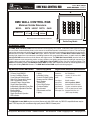
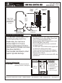
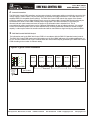
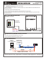
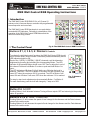
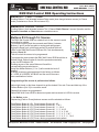
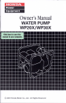
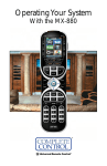
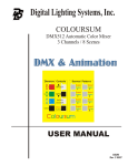
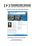
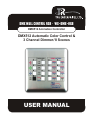
DMX WALL CONTROL RGB • WC–DMX–RGB
DMX512 Animation Controller
DMX512 Automatic Color Control &
3 Channel Dimmer / 8 Scenes
USER MANUAL
3 Color Mixer DMX512
DMX WALL CONTROL RGB
Visit us at:
www.tprlights.com
USER MANUAL – PAGE 1
W
DMX WALL CONTROL RGB
Maximum Outside Dimensions
MODEL
WC-DMX-RGB
WIDTH HEIGHT DEPTH
4.600"
117 mm
4.600"
117 mm
1.650"
042 mm
H
GANG
Double
DEPTH (D) includes circuit board with components
D
Double-Gang Models
INTRODUCTION
The DMX Wall Control RGB is a three-channel 8 scene lighting color control. 3 Individual channel dimming allows
the use of Red, Green and Blue primary color sources to create thousands of combinations of colors. This new design
employs the latest electronic technology and presents a control panel with a sleek modern look and simple to use controls.
Added features include a standard DMX-512 output. When in dynamic mode, the DMX Wall Control RGB creates
dazzling light shows from user selected crossfading between user programmable scenes. In static mode, the DMX
Wall Control RGB acts as a three-circuit dimmer with eight scenes. The DMX Wall Control RGB can also work in an
ON/OFF between scene sequencing mode. In short, whether your lighting project requires rapid light sequencing or
a more subtle cross-fade mixing of colors, the DMX Wall Control RGB provides you with a perfect solution. The
DMX-512 compatibility makes the DMX Wall Control RGB a perfect and inexpensive solution for retrofit applications by
working with existing DMX-512 dimmers. The DMX Wall Control RGB requires a double-gang box.
DMX Wall Control RGB FEATURES
•
•
•
•
•
•
•
•
•
•
•
•
•
•
Economical.
3 Channel Logic DMX512
8 scene Crossfading Patterns
Cross-Fade and Chase Modes
Static 3-Ch. Dimmer with 8 Scenes
User Programmable Scenes
Automatic Pattern Change Mode
Single Pattern Select Mode
Independently Adjustable Chase Rate
Independently Adjustable Fade Rate
Blackout Switch
Nonvolatile Memory
Simple Push Button Operation
LED Indicators
APPLICATIONS
•
•
•
•
•
•
•
•
•
•
Architectural & Decorative
Lighting
Landscape Lighting
Pond and Fountain Lighting
Museums and Art Galleries
Movie Theaters
Theme Parks
Point of Sale Displays
Christmas Displays
Sign Animation
Entertainment and Club
Lighting
Physical and Electrical Specifications
Back Plate:
Dimensions:
Voltage range:
Power:
Data Output:
Output Drive:
Data Format:
Data Retention:
ESD Protection:
DMX output Port:
Metal Construction
See Table Above
8 to12 V; 50 / 60 Hz or VDC
200 mAmps
RS485 Compliant
256 H. Impedance RS485
Standard DMX-512 Protocol
10 years, no batteries required
15 KV on data input and output
Standard RJ45 pins 1 & 2
(XLR5 output available)
The DMX Wall Control RGB requires an external dimmer pack with a DMX cable. Any DMX-512 compatible dimmer may be
used. TPR Enterprises, Ltd. manufactures high quality low cost DMX-512 dimmer packs.
644 Fayette Ave., Mamaroneck, NY 10543
PHONE: 914.698.1141
FAX: 914.698.9419
E-MAIL: [email protected]
www.tprlights.com
Visit us at:
www.tprlights.com
1.400"
36 mm
Screws (2)
6-32 x 1"
2-15/16"
75 mm
2-1/2"
64 mm
Inside Clearance
Power and DMX 512
control wires
Mounting requirements
Wiring Notes
• The DMX Wall Control RGB mounts
in double-gang deep electric box
•
• Double Gang box must have a
minimum depth of 2-1/2" and a
minimum inside height of 2-15/16" to
allow clearance for printed circuit board.
(See above illustration.)
• Use Grounded metal boxes to protect
against high static discharge .
•
•
•
•
•
All wiring between the DMX Wall Control RGB and
dimmerpacks is low voltage (NEMA Class 2) and
must be a shielded twisted pair cable.
Standard industry DMX-512 cables may be used
with the DMX Wall Control RGB.
Do not run DMX cable in the same conduit with
non-class 2 circuits.
The DMX Wall Control RGB must be supplied with
an external low voltage power supply.
Power for the wall control may be on a different
power phase from power supplying the DMX-512
dimmer packs or fixtures.
Installation must conform to local and/or NEC code
requirements.
1.810” - 46 mm
1.810"
8
Additional Circuitry
For 2-G Panels
4
5
6
PHONE: 914.698.1141
3
2
FAX: 914.698.9419
2.825" - 72 mm
Cross-Fader/Chaser/3-Channel
Dimming Controller, 2-Gang size.
644 Fayette Ave., Mamaroneck, NY 10543
Circuit Legend
46 mm
Ordering Information
WC-DMX-RGB:
USER MANUAL – PAGE 2
Typical Cover
Circuit
Height
Deep 2 Gang
Electric box
for hardwired
recessed mount
(by others)
3 Color Mixer DMX512
DMX WALL CONTROL RGB
1
1
2
3
4
5
6
7
8
Microprocessor
Nonvolatile Memory
Communications Chip
Quartz Crystal
Power Supply Capacitor
Voltage Regulator
Output Port
Buttons 9-16 Keypad
7
E-MAIL: [email protected]
www.tprlights.com
Visit us at:
www.tprlights.com
DMX WALL CONTROL RGB
3 Color Mixer DMX512
USER MANUAL – PAGE 3
A - General Information
The DMX Wall Control RGB controllers use low-power electronic components and do not not directly connect to high
voltage supply or electric loads. They are powered by an external low-voltage transformer. The loads connect to a
separate DMX-512 compatible dimmer pack(s). The DMX Wall Control RGB controls the outputs of the dimmer
pack(s) by sending a series of digital dimming levels over a low voltage cable. Several DMX dimmer packs may be
connected to the same control cable in a daisy-chain configuration. The DMX information is received by all
dimmers and each pack extracts and uses the portion of the information that is intended for it. This is
accomplished by setting each dimmer pack to a different DMX address by way of address selectors. It is possible
to have several dimmer packs set to the same address when controlling loads that exceeds the dimmer’s output
capacity. Loads may be broken into smaller sections and still be controlled as a single load by any particular DMX.
B - DMX Wall Control RGB DMX Output
The information sent by the DMX Wall Control RGB is in accordance with the DMX-512 standard control protocol.
The DMX Wall Control RGB sends control information over the first 3 DMX addresses. All remaining addresses, up
to 512, are sent a DMX off-level. Figure 2 below shows the various DMX outputs generated by the DMX Wall Control
RGB according to the number of channels setting.
Figure 1: Typical control installation
WP300
WP300
WP300
WP300
WP300
WP300
Address 00
Address 00
Address 00
Address 00
Address 00
Address 00
DMX Wall Control RGB
Voltage range
8 to 12 V
AC or DC
200 mA.
CAT5 cable
Patch type
644 Fayette Ave., Mamaroneck, NY 10543
To next Dimmer
CAT5 cable
PHONE: 914.698.1141
FAX: 914.698.9419
E-MAIL: [email protected]
www.tprlights.com
Visit us at:
www.tprlights.com
DMX WALL CONTROL RGB
3 Color Mixer DMX512
USER MANUAL – PAGE 4
C - Installation Instructions (See Figs. 4 & 5 below).
1. Install the DMX Wall Control RGB in a convenient location. Fig. 4 shows a DMX Wall Control RGB which has a
tail for power and DMX.
2. Provide power supply for the DMX Wall Control.
3. Install the DMX dimmer pack and follow the wiring instructions in its user manual.
4. Connect the DMX Wall Control RGB to the Dimmer Pack using a standard Cat5 patch or gross cable. Skip to
Operating Instructions.
Fig. 4: Typical DMX Wall Control RGB
to dimmers connection
8-12 V 50/60HZ or VDC
DMX Wall Control RGB
RJ45 Pins
PIN # 1 -DATA
PIN # 2 + DATA
E
To more DMX
Dimmer Packs
CAT5 cable
- DMX Wall Control RGB DMX and Power Connections
Use a tail to connect to DMX equipment as seen in Fig. 4.
Power and DMX pin assignments are shown in Fig. 5.
Fig. 5: WC-DMX-RGB Wiring
POWER SUPPLY
TO DMX512
3 – 4 ch. Dimmer packs
1
9-12VAC or
9-12 VDC
RJ45
12345678
Blue
P+
PIN# 1
PIN# 2
-D
+D
644 Fayette Ave., Mamaroneck, NY 10543
2.5mm Connector P-
1
Blue & White Stripes 4
ORANGE
-Data
2
ORANGE & WHITE STRIPES
+Data
3
PHONE: 914.698.1141
FAX: 914.698.9419
E-MAIL: [email protected]
www.tprlights.com
Visit us at:
www.tprlights.com
DMX WALL CONTROL RGB
3 Color Mixer DMX512
USER MANUAL – PAGE 5
DMX Wall Control RGB Operating Instructions
I. Introduction
The DMX Wall Control RGB DMX-512 is a 3 Channel (3
primary colors) 8 scenes dimmer controller with programmable
scene sequence and cross fade.
The DMX Wall Control RGB has simple to use push-button
controlswith LED indicators. Following is a description of the
operation of the DMX Wall Control RGB Buttons and the
various functions they perform.
II. The Control Panel
Buttons # 1, 2, 3 & 5, 6: Dimmers
1
5
9
13
2
6
10
14
3
7
11
15
4
8
12
16
Fig. 6: The DMX Wall Control RGB Front Panel
Controls
To activate the individual control functions, the DMX Wall Control RGB should
be on Dimmer Mode. Button number 8 should be pressed momentarily and its
LED indicator should be ON.
Each of the 1 (RED), 2 (GREEN), 3 (BLUE) channels could be dimmed or
brightened by pressing and releasing the corresponding Button. The LED
indicator of the pressed Button should come ON. Then to adjust the Level of
this channel Push and hold Button 5 to raise or push and hold Button 6 to
lower.
The LED indicators of Buttons 5 & 6 will both come ON when the level is
between 1 and 99%. The LED of Button 5 will come ON and of Button 6 will
come OFF when the maximum 100 % is reached. The LED of Button 6 will
come ON and of Button 5 will come OFF when the minimum 0 % is reached.
For step by step Level adjustment push momentarily Button 5 or Button 6 .
For each momentary push the level will change by 1 step out of 256.
1
5
2
6
3
7
4
8
Fig. 7: Dimmers
controls
Button # 4: All OFF
Pushing Button # 4 will alternate between Turning all three outputs OFF and returning to the previous
status of operation.
Buttons # 5 & 6: Fade / Chase rate
Pushing Button # 5 will increase the speed of level change for the dimmers and the Fade between
scenes in the action mode.
Pushing Button # 6 will decrease the speed of level change for the dimmers and the Fade between
scenes in the action mode.
644 Fayette Ave., Mamaroneck, NY 10543
PHONE: 914.698.1141
FAX: 914.698.9419
E-MAIL: [email protected]
www.tprlights.com
Visit us at:
www.tprlights.com
3 Color Mixer DMX512
DMX WALL CONTROL RGB
USER MANUAL – PAGE 6
DMX Wall Control RGB Operating Instructions
Button # 7: Fader / Chaser
Pushing Button # 7 will alternate between Fader mode (slow change between scenes) to Chaser
mode (instantaneous Scene ON and scene Off).
Button # 8: Dimmer / Action
Pushing Button # 8 will alternate between The 3 Channel Static Dimmer 8 scenes Operation and the
Dynamic Crossfade or Chase between selectable scenes.
Buttons # 9 through 16: Scenes
The DMX Wall Control RGB has a default lock for the scenes to avoid
overwriting by mistake.
To unlock the scenes push the recessed reset Button ( between
Buttons (1 and 5) under face plate or unplug and replug power.
During the Reset cycle which lasts around 10 seconds while all
LEDs on the DMX Wall Control RGB are ON, Push simultaneously
Buttons 12 and 16.
This will unlock the scenes to be programmed.
To program the scene presets the DMX Wall Control RGB should be on
Dimmer Mode; Button number 8 should be pressed momentarily
to turn its LED indicator ON.
Pushing anyone of the scene Buttons will recall the
corresponding prerecorded scene.
Using the dimmer Buttons (1, 2 or 3) will override the levels if
desired.
8 default scenes are preprogrammed in the factory as follows:
# 1 =RED; # 2=GREEN; # 3=BLUE and the rest of the scene
have combination of colors.
Programming of the scenes is performed as follows:
1
5
2
6
3
7
4
8
9
13
10
14
11
15
12
16
Fig. 8: Scene setup
Adjust Light levels on the three channels to get the desired Color mix. Press and hold any of the
Scenes Buttons (9 to 16) to record the scene.
Repeat till all scenes are programmed.
Reset DMX Wall Control RGB or disconnect power and reconnect to LOCK the scenes.
In the Motion mode:
Sequencing (Fade or Chase) between scenes could be selected as follows.
Push Pattern Button # 1 (9)
Push Pattern Button # 2 (10)
Push Pattern Button # 3 (11)
Push Pattern Button # 4 (12)
Push Pattern Button # 5 (13)
Push Pattern Button # 6 (14)
Push Pattern Button # 7 (15)
Push Pattern Button # 8 (16)
644 Fayette Ave., Mamaroneck, NY 10543
Runs between Scenes # 1 & 2
Runs between Scenes # 1 , 2 & 3
Runs between Scenes # 1 , 2 , 3 & 4
Runs between Scenes # 1 , 2 , 3 , 4 & 5
Runs between Scenes # 1 , 2 , 3 , 4 , 5 & 6
Runs between Scenes # 1 , 2 , 3 , 4 , 5 , 6 & 7
Runs between Scenes # 1 , 2 , 3 , 4 , 5 , 6 , 7 & 8
Runs a factory programmed auto pattern.
PHONE: 914.698.1141
FAX: 914.698.9419
E-MAIL: [email protected]
www.tprlights.com