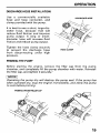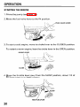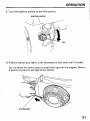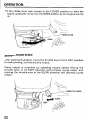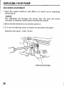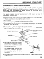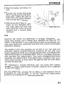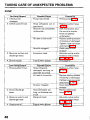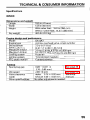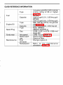
1
The engine exhaustfrom this product
contains chemicals known
to the State
of California to cause cancer, birth
Keep this owner's manualhandy, so you can refer toit a t any time.
Thisowner'smanual
is considered a permanentpartofthewater
pump and should remain with the water pump if resold.
The information and specifications included in this publication were in
effect at thetimeofapprovalforprinting.HondaMotor
Co., Ltd.
reserves the right, however, to discontinue or change specifications or
design a t any time without notice and without incurring
any obligation
whatever. No partofthispublicationmay
be reproducedwithout
written permission.
INTRODUCTION
A FEWWORDS ABOUT SAFETY
Your safety and the safetyof others are very important. And using this
water pump safely isan important responsibility.
To help you make informed decisions about safety, we have provided
operatingproceduresandotherinformationonlabelsandinthis
manual. This information alerts you to potential
hazards that could
hurt you or others.
Of course, it is not practical or possible to warn
you about all the
hazards associated with operating or maintaining a water pump. You
must use your own good judgment.
You willfindimportant
including:
safetyinformationin
a varietyofforms,
Safety Labels - on the pump.
Safety Messages - preceded by a safety alert symbol L?L and one
of three signal words,
DANGER, WARNING, or CAUTION.
These signal words mean:
You WILL be KILLED or SERIOUSLY HURT if
you don‘t follow instructions.
YouCAN beKILLED or SERIOUSLY HURT if
you don’t follow instructions.
You
CAN
be
instructions.
HURT ifyoudon’tfollow
Safety Headings - such as IMPORTANTSAFETYINFORMATION.
Safety Section - such as PUMP SAFETY
Instructions - how touse this pump correctly and
safely.
This entire book is filled with important safety information
read it carefully.
2
- please
I
CONTENTS
PUMP SAFETY ...........................................................................................
IMPORTANT SAFETY INFORMATION .................................................
SAFETY LABEL LOCATIONS .................................................................
5
5
7
CONTROLS & FEATURES .........................................................................
COMPONENT & CONTROL LOCATIONS .............................................
CONTROLS ...........................................................................................
Fuel Valve Lever ...............................................................................
Ignition Switch ..................................................................................
Choke Lever ......................................................................................
Throttle Lever ...................................................................................
Recoil Starter Grip ............................................................................
FEATURES ............................................................................................
Oil A l e e System ..............................................................................
8
8
10
10
10
11
11
12
12
12
BEFORE OPERATION ..............................................................................
ARE YOU READY TO GET STARTED?................................................
IS YOUR PUMP READY TO GO? .........................................................
Check the General Condition of the Pump.....................................
Check the Suction andDischarge Hoses........................................
Check the Engine ..............................................................................
13
13
14
14
15
15
OPERATION .............................................................................................
SAFE OPERATING PRECAUTIONS ....................................................
PUMP PLACEMENT .............................................................................
SUCTION HOSE INSTALLATION ........................................................
DISCHARGE HOSE INSTALLATION ...................................................
PRIMING THE PUMP ............................................................................
STARTING THE ENGINE .....................................................................
SETTING ENGINE SPEED ....................................................................
STOPPING THE ENGINE .....................................................................
16
16
17
18
19
19
20
22
23
SERVICING YOUR PUMP ........................................................................
THE IMPORTANCE OF MAINTENANCE .............................................
MAINTENANCE SAFETY .....................................................................
MAINTENANCE SCHEDULE ...............................................................
REFUELING ...........................................................................................
RECOMMENDATIONS
FUEL
..............................................................
ENGINE OIL LEVEL CHECK .................................................................
ENGINE OIL CHANGE..........................................................................
25
25
26
27
28
29
30
31
3
CONTENTS
SERVICING YOUR PUMP (continued)
ENGINE OIL RECOMMENDATIONS ...................................................
AIR FILTER INSPECTION .....................................................................
AIR FILTER CLEANING ........................................................................
SEDIMENT CUP CLEANING ................................................................
SPARK PLUG SERVICE ........................................................................
IDLE SPEED ADJUSTMENT ................................................................
SPARK ARRESTER SERVICE (optional equipment)..........................
32
33
34
35
36
38
39
STORAGE .................................................................................................
STORAGE PREPARATION ...................................................................
Cleaning ............................................................................................
Fuel ....................................................................................................
Engine Oil ..........................................................................................
STORAGE PRECAUTIONS ..................................................................
REMOVAL FROM STORAGE ...............................................................
40
40
40
41
44
44
45
TRANSPORTING ......................................................................................
46
TAKING CARE OF UNEXPECTED PROBLEMS......................................
ENGINE .................................................................................................
Engine Will Not Start.......................................................................
Engine Lacks Power .........................................................................
PUMP ....................................................................................................
No Pump Output ..............................................................................
Low Pump Output............................................................................
47
47
47
47
48
48
48
TECHNICAL & CONSUMER INFORMATION .........................................
49
TECHNICAL INFORMATION ................................................................
49
Serial Number Location...................................................................
49
Carburetor Modification for High Altitude Operation...................50
Oxygenated Fuels ............................................................................ 51
Emission Control System Information ...........................................
52
Air Index ............................................................................................ 54
Specifications ...................................................................................
55
CONSUMER INFORMATION ...............................................................
59
Honda Publications ..........................................................................
59
Customer Service Information ........................................................
60
QUICK REFERENCE INFORMATION
4
............................
Inside back cover
IMPORTANT SAFETY INFORMATION
Honda WP2OX and WP3OX pumps are designed to pump only water
that is not intended for human consumption, and other
uses can result
in injury to the operator or damage to the pump and other property
Most accidents can be prevented if you follow all instructions in this
manual and on the pump. The most common hazards are discussed
below, along with the best way to protect yourself and others.
Operator Responsibility
It is the operator’s responsibility to provide the necessary safeguards
to protect people and property. Know how
to stop the pump quickly in
case of emergency. If youleave the pump for anyreason, always turn
the engine off. Understand theuse of all controls and connections.
Be sure that anyonewhooperatesthepump
instruction. Do not let children operate the pump.
pets away from the
area of operation.
receives proper
Keep children and
Pump Operation
Pumponlywaterthatisnotintendedforhumanconsumption.
Pumping flammable liquids, suchas gasoline or fuel oils, can result in
afireorexplosion,causingseriousinjury.Pumping
sea water,
beverages, acids, chemical
solutions,
or
any
other
liquid
that
promotes corrosion can damage the pump.
Refuel With Care
Gasoline is extremely flammable, and gasoline vapor can explode.
Refuel outdoors, in a well-ventilated area, with the engine stopped and
the pump on a level surface. Do not fill the fuel tank above the fuel
strainer shoulder. Never smoke near gasoline, and keep other flames
and sparksaway. Always store gasoline in an approved container.
Make sure that any spilled fuelhas been wiped up before starting the
engine.
5
PUMP SAFETY
Hot Exhaust
The muffler becomes very hot during operation and remains hot for
a
while after stopping the engine. Be careful not to touch the muffler
while it is hot. Let the engine cool before transporting the pump or
storing it indoors.
To prevent fire hazards, keep the pump a t least 3 feet ( 1 meter) away
from building walls and other equipment during operation.
Do not
place flammable objects close to the engine.
Carbon Monoxide Hazard
Exhaust gas contains poisonous carbon monoxide. Avoid inhalation of
exhaust gas. Never run the engine in
a closed garage or confinedarea.
PUMP SAFETY
SAFETY LABEL LOCATION
The label shown here contains important safety information.
Please
read it carefully. This label is considered a permanent part of your
pump. If the label comes off or becomeshard to read, contactan
authorized Honda servicing dealer for a replacement.
7WARNINGDO NOT PUMP
FLAMMABLE
OR CORROSIVEMATERIALS.
AN EXPLOSION OR FIRE
COULD RESULT, CAUSING
, SEVERE PERSONAL INJURY.
7
CONTROLS & FEATURES
COMPONENT & CONTROL LOCATIONS
<WPPOX >
FUEL
FILLER
CAP
DISCHARGE
PORT
THROlTLE LEVER
CHOKE LEVER
FUEL VALVE LEVER -
OIL FILLER CAP/DIPSTICK
IGNITION SWITCH
FRAME
PRIMING W
FILLER CAP
SUCTION PORT
STRAINER
PUMP DRAIN PLUG
8
CONTROLS & FEATURES
<WP3OX >
FUEL FILLER CAP
DISCHARGE PORT
THROlTLE LEVER
\
CHOKE LEVER
FUEL VALVE LEVER
”
-
OIL FILLER CAP/DIPSTICK
7,
IGNITION SWITCH
MUFFLER
\
9
CONTROLS & FEATURES
CONTROLS
Fuel Valve Lever
The fuel valve opens and closes
the connection between the fuel
tank and the carburetor.
FUEL VALVE LEVER
I
'-i
The fuel valve lever must be in the
ON position for the engine
to run.
Whentheengineisnot
in use,
leave the fuel valve lever in the
O F F p o s i t i o nt op r e v e n t
carburetor flooding and to reduce
the possibility of fuel
leakage.
OFF .'
Ignition Switch
IGNITION SWITCH
Theignitionswitchcontrolsthe
ignition system.
The ignition switch must bein the
ON position for the engine to run.
Turning the ignition switch to the
OFF position stops the engine.
10
.----
CONTROLS & FEATURES
Choke Lever
CHOKE
LEVER
The choke lever opens and closes
the choke valvein the carburetor.
t
enriches
The CLOSED position
the fuel mixture for startinga cold
engine.
The OPEN positionprovidesthe
correct fuel mixture for operation
after starting, and for restarting a
warm engine.
CL
Throttle Lever
The throttle lever controls engine
speed.
Movingthethrottleleverinthe
directionsshownmakesthe
engine run faster or slower.
by
Pump
output
is
controlled
adjustingthethrottle
lever. At
maximumthrottleposition,the
pumpwilldeliverthehighest
o u t p uvt o l u m eM
. o v i n gt h e
throttle
lever
toward
the
idle
position will decrease the output
volume of the pump.
11
CONTROLS & FEATURES
Recoil Starter Grip
Pulling the starter grip operates
the recoil starterto crank the engine.
STARTER GRIP
FEATURES
Oil Alert@ System
The Oil Ale@ system is designed t o prevent engine damage caused
by an insufficient amount of oil in the
crankcase. Before the oil level in
the crankcase can fall below a safe limit, the Oil Ale@ system
will
automatically stop the engine (the ignition switch
will remain in the
ON position).
If the engine stops and
will not restart, check the engine oil level (page
30 ) before troubleshooting in other
areas.
12
ARE YOU READY TO GET STARTED?
Your safety is your responsibility. A little time spent in preparation will
significantly reduce your risk of injury.
Knowledge
Read and understand this manual. Know what the controls do and
how tooperate them.
Familiarize yourself with the pump andits operation before you begin
pumping. Know what todo in case of emergencies.
Be sure of what you are pumping. This pump is designed to pump
only water thatis not intended for human consumption.
13
IS YOUR PUMP READY TO GO?
For your safety, and to maximize the service life of your equipment,it
is very important totake a few moments before you operate the pump
to check its condition. Be sure to take care of any problem you find, or
have your servicing dealer correct it, before you operate the pump.
Improperly maintaining this pump,
or failing to correct
a problem
before operation, couldcause a
malfunction in which you could
be
seriously injured.
Always perform a preoperation
inspection beforeeach operation,
and correct any problem.
Exhaust gas contains poisonous carbon monoxide. Avoid inhalation of
exhaust gas. Never run the engine
in a closed garage or confinedarea.
To prevent fire hazards, keep the pump a t least 3 feet (1 meter) away
from building walls and other equipment during operation.
Do not
place flammable objects close to the engine.
Before beginning your preoperation checks, be sure the pump is on a
level surface and the ignition switch
is in theOFF position.
Check the General Conditionof the Pump
Look around and underneath the pump for signs of oil or gasoline
leaks.
Remove any excessive dirt or debris, especially around the engine
muffler, and recoil starter.
Look for signs of damage.
Check that all nuts, bolts, screws, hose connectors and clamps are
tightened.
14
BEFORE OPERATION
Check the Suction and Discharge Hoses
Check the general condition of the hoses. Be sure the hoses are in
serviceable
condition
before
connecting
them
to
the
pump.
Remember that the suction hose must be reinforced construction to
prevent hosecollapse.
Check that the sealing washer in the suction hose connector is in
good condition(see page18 1.
Check that the hose connectors and clamps
(see pages 18 & 19 ).
are securely installed
Check that the strainer is in good condition and is installed on the
suction hose (see page 18 1.
Check the Engine
Check the oil level (see page 30). To avoid the inconvenience of an
unexpected shutdown by the Oil Alert@ system, always check the
engine oil level before startup.
Check the air filter(see page33 ), A dirty air filterwill restrict air flow
to thecarburetor, reducing engine andpump performance.
Check the fuel level (see page 28). Starting with a full tank will help
to eliminate or reduce operating interruptions for refueling.
15
SAFE OPERATING PRECAUTIONS
To safely realize the full potential of this pump, you need a complete
understanding of its operation and a certain amount of practice with
its controls.
Before operatingthepumpforthefirsttime,
please reviewthe
IMPORTANT SAFEN INFORMATION on page 5 and the chapter titled
BEFORE OPERA TION.
For your safety, avoid starting or operating the engine in an enclosed
area, such as agarage. Your engine’s exhaust contains poisonous
carbon monoxide gas which can collect rapidly
i n an enclosed area
and cause illness ordeath.
Pumponlywaterthatisnotintendedforhumanconsumption.
Pumping flammable liquids, suchas gasoline or fueloils, can result in
afireorexplosion,causingseriousinjury.Pumping
sea water,
beverages, acids, chemical
solutions,
or
any
other
liquid
that
promotes corrosion can damage
the pump.
16
OPERATION
PUMP PLACEMENT
For best pump performance, place the pump near the water level, and
usehosesthat are no longer than necessary. That will enablethe
pump to produce the
greatest output with the
least self-priming time.
As head (pumping
height)
increases, pumpoutput
decreases.
Maximum headspecificationsand
pumpperformancecurves
are
shown in the tables on pages56 and 58. The length, type, and size of
the suction and discharge hoses
can also significantly affect pump
output.
Discharge
head
capability
is
always
greater
than
suction
head
capability, so it is important for suction head to be the shorter part of
total head.
is
Minimizing suction head (placing the pump near the water level)
also very important for reducing self-priming time. Self-priming time
is the timeit takes the pump to bring water the distance of the suction
head during initial operation.
17
OPERATION
SUCTION HOSE INSTALLATION
Use the commercially available hose and hose connector
with the
hoseclampprovided
with thepump.Thesuction-hosemustbe
reinforced with a noncollapsible wall or braided wire construction.
The
suction
hose
should
be
no
longer
than
necessary. Pump
performance is best when the pump is near the water level, and the
hoses are short.
Use a hose clampto securely fasten the hose connectorto the suction
hose in order to prevent air
leakage and loss of suction. Verify that the
hose connector sealing washer is in good condition.
Install the strainer (provided with the pump) on the other end of the
suction hose, and secure it with a hose clamp. The strainerwill help to
or damaged by debris.
prevent the pump from becoming clogged
pump suction port.
Securely tighten the hose connector on the
SUCTION PORT
HOSE CLAMP RING
SUCTION HOSE
HOSE CONNEC
18
OPERATION
DISCHARGE HOSEINSTALLATION
Use
a
commercially
available
hoseandhoseconnector,
and
clamp providedwith the pump.
DISCHARGE HOSE
It is best to use a short, large-diameter hose,
because
that will
reduce fluid friction and improve
pumpoutput. A longorsmalldiameter hose will increase fluid
friction and reduce pump output.
Tighten
hose
clamp
securely
the
to prevent
the
discharge
hose
from
disconnecting
under
high
pressure.
I
HOSE CLAMP
PRIMING THE PUMP
Beforestartingthe
engine, removethefillercapfrom
the pump
chamber, and completely fill the pump chamber with water. Reinstall
the fillercap, and tightenit securely.'
m
Operating the pump dry willdestroy the pump seal. If the pump has
been operated dry, stop the engine immediately, and allow the pump
to cool before priming.
PRIMING WATER FILLER CAP
'\.\..j
1
19
OPERATION
STARTING THE ENGINE
1. Prime the pump(see page19 ).
2. Move the fuel valve lever to ON
the position.
'
FUEL VALVE LEVER
3. To start a cold engine, move thechoke lever to the CLOSED position.
To restart awarm engine, leave the choke leverin the OPEN position.
CL
4. Move the throttle lever away from theSLOW position, about 1/3 of
the way toward the
FAST position.
THROT~LELEVER
20
OPERATION
5. Turn the ignition switch to the
ON position.
IGNITION SWITCH
6. Pull the starter grip lightly until
resistance is felt, then pull it briskly.
Do not allow the starter grip to snap
back against the engine. Return
it gently to prevent damage to the starter.
STARTER GRIP
21
OPERATION
7. If the choke lever was moved to the
CLOSED position to start the
engine, gradually moveit to theOPEN position as the engine warms
UP-
; \\
--CHOKE LEVER
SETTING ENGINESPEED
After starting the engine, move the throttle lever to theFAST position
for self-priming, andcheck pump output.
Pumpoutputiscontrolled
by adjustingengine speed. Moving the
throttle lever in the
FAST direction will increase pump output, and
moving the throttle lever in the SLOW direction will decrease pump
output.
22
OPERATION
STOPPING THE ENGINE
To stop the engine inan emergency, simply turn the ignition switch to
the OFF position.
Under
normal
conditions,
use the
following
procedure.
1. Move the throttle lever to SLOW
the
position.
2. Turn the ignition switch to the
OFF position.
IGNITION SWITCH
23
OPERATION
3. Turn the fuel valve lever to OFF
the position.
After use, remove the pump drain plug (see page41 1, and drain the
pump chamber. Remove the filler cap, and flush the pump chamber
with clean, freshwater.Allowthewatertodrainfromthepump
chamber, then reinstall the fillercap and drain plug.
24
.
'
SERVICING YOUR PUMP
THE IMPORTANCE OF MAINTENANCE
Good maintenance is essential for safe, economical, and trouble-free
operation. It will also help reduce air pollution.
Improperly maintaining this pump,
or failure to correct a problem
before operation, can cause a
malfunction in which you can be
seriously hurt orkilled.
Always follow the inspection and
maintenance recommendations and
schedules in this owner's manual.
To help you properlycare for your pump, the following pages include
a maintenance schedule, routine inspection procedures, and simple
maintenance procedures using basic hand tools. Other service tasks
that are more difficult, or require special tools, are best
handled by
professionals and are normally performed by a Honda technician or
other qualified mechanic.
The maintenance schedule applies to normal operating conditions. If
you operate your pump under severe conditions, such as sustained
high-load or high-temperature operation, or use in unusually wet or
dusty conditions, consult your servicing dealer for recommendations
applicable to your individualneeds and use.
Rememberthatyourservicing
dealer knowsyourpumpbestandis
it.
fully equipped to maintain and repair
To ensurethebestqualityandreliability,useonly
new, genuine
Honda partsor their equivalents for repair and replacement.
Maintenance, replacement, or repair of emission control devices and
systems may be performed by any engine repair establishment or
individual, using parts that are "certified" to EPA standards.
25
SERVICING YOUR PUMP
MAINTENANCE SAFETY
Some of the most important safety precautions follow. However, we
cannotwarnyouofeveryconceivable
hazard thatcan
arise in
performing maintenance. Only you
can decide whether or not you
should performa given task.
Failure to properly follow
maintenance instructions and
precautions cancause you tobe
seriously hurt orkilled.
Always follow the procedures and
precautions in the owner’s manual.
Safety Precautions
Make sure the engine is off before you begin any maintenance or
repairs. Thiswill eliminate several potential hazards:
-Carbon monoxide poisoning from engine exhaust.
Be sure there is adequate ventilation whenever you operate the
engine.
-Burns from hot parts.
Let the engine and exhaust system cool before touching.
-Injury from moving parts.
Do not run the engine unless instructed toso.
do
Read the instructions before youbegin, and make sure you have the
tools and skills required.
Toreduce thepossibilityoffireorexplosion,becarefulwhen
workingaroundgasoline.Useonly
a nonflammablesolvent,not
gasoline, to clean parts. Keep cigarettes, sparks, and flames away
from all fuel-relatedparts.
26
SERVICING YOUR PUMP
MAINTENANCE SCHEDULE
Every
3 months
or
50 Hrs.
Every
6 months
or
100 Hrs.
Every
year
or
300 Hrs.
n
0(1)
n
0
0
0
!revery 5 1 Hrs (2)
chamber
Check
Every
tube
Fuel
Impeller
Impeller clearance
Pump inlet valve
2 years
(Replace
if necessary) (2)
Check
Check
Check
0 (2)
0 (2)
0 (2)
Emission-related items.
(1) Service more frequently whenused in dusty areas.
(2) These itemsshouldbeservicedbyyourservicing
dealer, unless you
have the proper tools and are mechanically proficient.
Refer t o Honda
shop manual forservice procedures.
(3) For commercial use, log hours of operationtodetermineproper
maintenance intervals.
27
SERVICING YOUR PUMP
REFUELING
Fuel tank capacities
WP2OX: 0.66 US gal (2.5 !J,0.55 Imp gal)
WP3OX: 0.95 US gal (3.6 0 ,0.79 Imp gal)
With the engine stopped, remove the fuel tank cap andcheck the fuel
level. Refill the tank if the fuel level is low.
Gasoline is highly flammable and
explosive.
You can be burned or seriously
injured when handling fuel.
Stop the engine and
keep heat,
sparks, and flame away.
Handle fuel only outdoors.
Wipe up spills immediately.
MAXIMUM FUEL LEVEL
-
28
-
-
SERVICING YOUR PUMP
Refuel in a well-ventilated area before starting the engine. If the engine
has been running, allowit to cool. Refuelcarefully to avoid spillingfuel.
Do not fill the fuel tank above the fuel strainer shoulder. After refue
tighten the fuel tank cap securely.
Never refuel the engine inside a building where gasoline fumes may
reach flames orsparks. Keep gasoline awayfrom appliance pilotlights,
barbecues, electric appliances, power tools,etc.
Spilled fuel is not only a firehazard, it causes environmental damage.
Wipe up spills immediately.
Fuel can damage paint and plastic. Be careful not to spill fuel when
filling your fuel tank. Damage caused by spilled fuel is not covered
under warranty.
FUEL RECOMMENDATIONS
Use unleaded gasoline with a pump octane rating of 86 or higher.
These engines are certifiedto operate on unleaded gasoline. Unleaded
gasoline produces fewer engine and spark plug deposits and extends
exhaust system life.
Never use stale or contaminated gasoline or an oil/gasoline mixture.
Avoid getting dirt or water in the tank.
fuel
Occasionally youmay
hearalight"spark
knock" or"pinging"
(metallic rapping noise) while operating under heavy loads. This is no
cause for concern.
Ifsparkknock
or pinging occurs a t asteadyengine
speed, under
normal load, change brands of gasoline. If spark knock
or pinging
persists, see an authorized Honda servicing dealer.
1Running the engine with persistent spark knock or pinging can cause
engine damage.
Running the engine with persistent spark knock or pinging is misuse,
and the Distributor's Limited Warrantydoes not cover parts damaged
by misuse.
29
SERVICING YOUR PUMP
~
~
ENGINE OIL LEVEL CHECK
Check theengineoillevelwiththeenginestoppedandinalevel
position.
1. Remove the oil filler cap/dipstick and wipe
it clean.
2. Insert and remove the dipstick without screwing
it into the fillerneck.
Check the oil level shown on the dipstick.
3. If the oil level is low, fill to the edge
recommended oil(see page 32).
of the oil filler hole with the
4. Screw in the oil filler cap/dipstick
securely.
FILLER CAP/DIPSTICK
LOWER LIMIT
The Oil Alert@ system will automatically stop the engine before the oil
level falls below safe limits.
However, to avoid the inconvenience of an
unexpected shutdown, check the oil level regularly.
30
SERVICING YOUR PUMP
ENGINE OIL CHANGE
Drain the used oil while the engine is warm. Warm oil drains quickly
and completely.
1. Place a suitable container below the engine
to catch the used oil,
then remove the oil filler cap/dipstick
and the drain plug.
2.Allow the used oil to drain completely, then reinstall the drain plug,
and tightenit securely.
Please dispose of used motor oil
in a manner that is compatible with
the environment. We suggest you
take used oil in a sealed container
to your local recycling center or service station for reclamation. Do
not throwit in the trash ,pour
it on the ground, or down a drain.
3. With the engine in a level position, fill to the outer edge of the oil
filler hole with the recommended (see
oil page 32 ).
Engine oil capacity: 0.63 US qt (0.60 0, 0.53 Imp qt)
The Oil Ale@ system will automatically stop the engine before the
the
oil
level
falls
below
the
safe limit. However, to avoid
inconvenience of an unexpected shutdown, fill
to the upper limit,
and check the oil level regularly.
4. Screw in the oil filler cap/dipsticksecurely.
OIL LEVEL
DRAIN PLUG
OIL FILLER CAP/DIPSTICK
31
I
1
SERVICING YOUR PUMP
ENGINE OIL RECOMMENDATIONS
Oil is a major factor affecting performance and service life. Use
4-stroke automotive detergent oil.
SAE IOW-30 is recommended for generaluse. Other viscosities shown
in the chart may be used when the average temperature
in your area is
within the recommended range.
SAE Viscosity Grades
SAE
1
1
1
1
1OW-30
I
5w-30
TEMP
-20
-30
I
I
A
0
I
-20 -10
8OI lw, OF
1O 20 30 40°C
20 , 40 , 60
0
I
AMBIENT TEMPERATURE
The SAE oil viscosity and service classification are in the API label o n
theoilcontainer.Hondarecommends
that you use API SERVICE
category SJ oil.
The recommended operating range of this pump 23
is O F to 104 OF (-5
"C to 40 "C).
32
SERVICING YOUR PUMP
AIR FILTER INSPECTION
Unscrew the wing nut and remove the cleaner
air
cover. Check the air
filter to be sureit is clean and in good condition.
it as described on page 34. Replace the air
If the air filter is dirty, clean
filter ifit is damaged.
Reinstall the air filter and air
cleaner cover. Be sure all the parts shown
below are in place. Tighten the wing nut securely.
pEE-1
Operating the engine without an air filter, or witha damaged air filter,
will allow dirt toenter the engine, causingrapid enginewear. Thistype
of damage isnot covered by the Distributor's Limited Warranty.
NUT
AIR CLEANER COVER
COVER WASHER
FILTER
GRID
33
SERVICING YOUR PUMP
AIR FILTER CLEANING
A dirty air filter will restrict air flow to the carburetor, reducing engine
performance. If you operate the pump in very dusty areas, clean the
airfiltermorefrequentlythanspecifiedinthe
MAINTENANCE
SCHEDULE (see page27 1.
1. Clean the air filter
in warm soapy water, rinse, and allow to dry
thoroughly. Or clean in nonflammable solvent and allow to dry.
2. Dip the air filter in clean engine oil, then squeeze out all excess oil.
The engine will smoke when started if too much oil
is left in the
foam.
3. Wipe dirt from the air cleanerbase and cover, using a moist rag. Be
careful to prevent dirt from entering the air duct that leads to the
carburetor.
34
SERVICING YOUR PUMP
SEDIMENT CUP CLEANING
1. Move the fuel valve lever to theOFF position, then remove the fuel
sediment cup and O-ring.
Gasoline is highly flammable and
explosive.
You can be burned or seriously
injured when handling fuel.
Stop the engine andkeep heat,
sparks, and flame away.
Handle fuel only outdoors.
Wipe up spills immediately.
2. Wash the sediment cup and O-ring in nonflammable solvent, and
dry them thoroughly.
3. Place the O-ring in the fuel
valve,and
Tighten the sediment cup securely.
install the sediment cup.
4. Move the fuel valve lever to the ON position, and check for leaks.
Replace the O-ring if there
is any leakage.
35
SERVICING YOUR PUMP
SPARK PLUG SERVICE
In order to service the spark plug, youwill need a spark plug wrench
(commercially available).
Recommended spark plug: BPR6ES (NGK)
W20EPR-U (DENSO)
p
q
i
Incorrect spark plugs can causeengine damage.
1. Disconnect the spark plug
cap, and remove anydirt from around the
spark plug area.
2. Remove the spark plug with13/16-inch
a
spark plug wrench
3. Inspect the spark plug. Replace
it if the electrodes are worn, or
iftheinsulatoris
cracked or
chipped. Clean thesparkplug
with a wirebrush
if you are
going toreuse it.
4 . M e a s u r et h es p a r kp l u g
electrodegapwithasuitable
gauge.
Correct thegap, if necessary, by
carefully
bending
the
side
electrode.
The gap should be:
0.028-0.031 in (0.70-0.80 mm)
36
0.028-0.031 in
(0.70-0.80 rnrn)
SERVICING YOUR PUMP
5. Install thespark plug carefully, by hand, to avoid cross-threading.
6.Afterthe spark plug seats, tightenwitha
wrench to compress the
washer.
13/16-inchspark
plug
If reinstalling the used spark plug, tighten 1/8-1/4 turn after the
spark plug seats.
If installing a new spark plug, tighten 1/2 turn after the spark plug
seats.
pi6K-l
A loose spark plug can overheatand damage the engine.
Overtightening the spark plug can damage the threads in the
cylinder head.
7. Attach the spark plug
cap.
37
SERVICING YOUR PUMP
IDLE SPEEDADJUSTMENT
1.Stat-t the engine outdoors, and allow
temperature.
it to warm up
to operating
1Dry operation will damage the pump seal. Be surethe
chamber is filled withwater before starting theengine.
2. Move the throttle lever to its slowest position.
3. Turn the throttle stop screw to obtain the standardspeed.
idle
Standard idle speed: 1,400 ?% rpm
'\
THROTTLE STOPSCREW
38
pump
SERVICING YOUR PUMP
SPARK ARRESTER SERVICE(optional equipment)
Your engine is not factory-equipped
with a spark arrester. In some
areas, it is illegal to operate an engine without aspark arrester. Check
local
laws
and
regulations.
A
spark
arrester
is
available
from
authorized Honda servicing dealers.
Thesparkarrester
mustbeservicedevery
functioning as designed.
100 hoursto
keep it
If the engine has been running, the muffler
will be very hot. Allow the
muffler to cool before servicing
the spark arrester.
1. Remove the two8 m m nuts, and remove the muffler.
2. Remove the four5 m m self-tapping screws, and remove the muffler
protector from the muffler.
3. Remove the 4 m m screw from the spark arrester, and remove the
spark arresterfrom the muffler.
5 mm SELF-TAPPING
MUFFLER PROTECTOR
4 mm SCREW
SPARK ARRESTER
4. Use a brush to remove carbon
deposits from the spark arrester
screen. Be careful
to
avoid
damaging thescreen.
The spark arrester must be free
of breaks andholes.
Replace
the
spark
arrester
if
it i s
damaged.
SCREEN
5. Install the spark arrester and muffler protector in the reverse order
of disassembly.
39
STORAGE
STORAGE PREPARATION
Properstoragepreparationisessentialforkeepingyourpump
troublefree and looking good.
The following steps will help to keep
rust
and
corrosion
from
impairing
your
pump’s
function
and
appearance, and will make the engine easierto start when youuse the
pump again.
Cleaning
1. Wash the engine and pump.
Wash the engine by hand, and
be careful to prevent water from
entering the air cleaner or muffler opening. Keep water away from
controlsand all other places that are difficulttodry,
as water
promotes rust.
-
1-
Using a garden hose or pressure washing equipment can force
water into the air cleaner or muffler opening. Water in the air
cleaner will soak the air filter, and water that passes through the
air filteror muffler can enterthe cylinder, causing damage.
Water contacting a hot engine can cause damage. If the engine
has been running, allow it to cool for at least half an hour before
washing.
2. Wipe dry all accessible surfaces.
3. Fill the pump chamber with
clean, freshwater, start the engine
outdoors,
and
let it run
until
it reaches normal
operating
temperature to evaporate any external water.
p7EE-l
Dry operation will damage the pump seal. Be sure the pump
chamber is filled withwater before starting the engine.
40
STORAGE
4. Stop the engine, and allow it to
cool.
5. Remove the pump drain
plug,
and flush the pump with clean,
fresh water. Allow the water to
drain from the pump chamber,
then reinstall the drain plug.
6. After the pump is clean and
dry,
touchupanydamagedpaint,
andcoat areas thatmayrust
with a light film of oil. Lubricate
controlswith a siliconespray
lubricant.
Fuel
Gasoline will oxidizeanddeteriorate
in storage.Oldgasoline
will
cause hardstarting,and
it leaves gum deposits that clog the fuel
system. If the gasoline in your engine deteriorates duringstorage, you
may need to. have the carburetor and other fuel system components
serviced or replaced.
The length of time that gasoline can be left in your fuel tank and
carburetor without causing functional problems
will vary with such
factors as gasoline blend, your storage temperatures, and whether the
fuel tank is partially or completely filled. Theinair
a partially filled fuel
tankpromotesfueldeterioration.
Very warmstorage/temperatures
accelerate fuel deterioration. Fuel deterioration problems may occur
within a few months, or even less if the gasoline was not fresh when
you filled the fuel tank.
The Distributor’s Limited Warranty doesnotcoverfuelsystem
damage or engine performance problems resulting from neglected
storage preparation.
Youcanextendfuelstoragelife
by adding a fuel stabilizer that
formulatedforthatpurpose,oryoucanavoidfueldeterioration
problems by draining the fuel tank and carburetor.
is
41
STORAGE
Adding a Fuel Stabilizer to Extend FuelStorage Life
When adding a fuel stabilizer, fill the fuel tank with fresh gasoline. If
onlypartiallyfilled,airinthe
tank willpromotefueldeterioration
during storage. If you keep a container of gasoline for refueling, be
sure that it contains only fresh gasoline.
1. Add fuel stabilizer following the manufacturer's instructions.
2.After adding a fuel stabilizer, run the engine outdoors for
10 minutes
to be sure that treated gasolinehas replaced the untreated gasoline
in the carburetor.
INOTICE
I
Dry operation will damage the pump seal. Be sure thepump
chamber is filled withwater before starting the
engine.
3. Stop theengine, and move the fuel valve lever to OFF
the position.
FUEL VALVE LEVER
\
OFF
42
STORAGE
Draining the Fuel Tank and Carburetor
1. Place an approved gasoline container below the carburetor, and
use
a funnel to avoid spilling fuel.
2. Remove the carburetor drain bolt and sediment cup, then move the
fuel valve lever to the
ON position.
Gasoline is highly flammable and
explosive.
You can be burned or seriously
injured when handling fuel.
Keep heat, sparks, and flame
away.
Handle fuel only outdoors.
Wipe up spills immediately.
DRAIN BOLT
.SEDIMENT CUP
3.After all the fuel has drained into the container, reinstall the drain
bolt and sediment cup. Tighten them securely.
43
STORAGE
Engine Oil
1. Change the engine oil(see page31 ).
2. Remove the spark plug
(see page36 1.
3. Pour a tablespoon(5-10 cc) of clean engine oil into the cylinder.
4. Pull the starter grip several times
to distribute the oilin the cylinder.
5. Reinstall the spark plug.
6. Pull the starter grip slowly until resistance is felt and the notch on
the starter pulley aligns with the hole at the top of the recoil starter
cover. This will close the valvesso moisture cannot enter the engine
cylinder. Return the starter grip gently.
-Align notch on pulley with
hole at top of cover.
STORAGE PRECAUTIONS
If yourpump will bestoredwithgasoline
in thefueltankand
carburetor, it is important to
reducethe hazard of gasolinevapor
ignition. Select awell-ventilated storage area away from any appliance
that operates with a flame, such as a furnace, water heater, or clothes
dryer. Also avoid any area with a spark-producing electric motor, or
where power toolsare operated.
If possible,avoidstorage
areas withhighhumidity,
promotes rust and corrosion.
because that
Unless all fuel has been drained from thetank,
fuel leave the fuel valve
lever in theOFF position to reduce the possibility of fuel
leakage.
44
STORAGE
Place the pump on a level
surface. Tilting can cause fuel or oilleakage.
With the engine and exhaust system
cool, cover the pump tokeep out
dust. A hotengineandexhaustsystemcanigniteormeltsome
materials. Do not use sheet plastic as a dust cover.A nonporous cover
will trap moisture around the pump, promoting rust and corrosion.
REMOVAL FROM STORAGE
'
Check your pump as described in the BEFORE OPERATlONchapter of
this manual.
If the fuel was drained during storage preparation, fill the tank
with
fresh gasoline. If you keep a container of gasoline for refueling, be
it containsonlyfreshgasoline.Gasolineoxidizesand
surethat
deteriorates over time, causing hard starting.
If the cylinder was coated with oil during storage preparation, the
engine may smoke briefly at startup. This is normal.
45
TRANSPORTING
If the pumphas been running, allow the engineto cool fora t least 15
minutesbeforeloadingthepumponthetransportvehicle.
A hot
engine and exhaustsystemcanburnyouandcanignitesome
materials.
Keep the pump level when transporting to reduce the possibility of
fuel leakage. Move the fuel valve lever to OFF
the position.
46
ENGINE
Engine Will Not Start
CausePossible
Correction
1. Check control
positions.
Choke open.
Ignitionswitch OFF.
I
I
Move choke lever to
CLOSED position
unless engine is warm.
Turnignitionswitchto
fuel.of Out
Refuel (p. 28
Bad fuel; pumpstoredDrainfueltankand
without
treating
carburetor
or
(p. 43 ).
draining gasoline, or
Refuel with
fresh
refuel
with
bad
gasoline
(p.
28 1.
gasoline.
Lowoil level caused Oil
Add oil (p. 30 1.
3. Check engine oil
Ale@ to stop engine.
level.
Spark plug
faulty,
Clean, gap, or replace
4. Remove and inspect
fouled,orimproperly
spark plug(p. 36 1.
spark plug.
gapped.
2. Check fuel.
Dry and reinstallspark
plug. Start engine with
throttle lever inFAST
position.
Replace or repair faulty
components as
necessary.
Spark plug wet with
fuel (flooded engine).
5. Take engine to an
authorized Honda
servicing dealer, or
refer to shop manual.
Fuel filter clogged,
carburetor malfunction,
ignition malfunction,
valves stuck, etc.
Engine Lacks Power
1. Check air filter.
Possible Cause
Air filter clogged.
2. Check fuel.
Bad fuel; pump stored
without treating or
draining gasoline, or
refuel with bad
gasoline.
Fuel filter clogged,
carburetor malfunction,
ignition malfunction,
valves stuck, etc.
~
authorized Honda
servicing dealer, or
t
Correction
Clean or replace filter
(P. 34 1.
Drain fuel tank and
carburetor (p. 43 1.
Refuel with fresh
gasoline (p. 28 ).
Replace or repair faulty
components as
necessary.
TAKING CARE OF UNEXPECTED PROBLEMS
PUMP
No Pump Output
1. Check pump
chamber.
2. Check suction hose.
Possible Cause
Pump not primed.
Correction
Prime pump(p. 19 )
Hosecollapsed, cut or
punctured.
Strainer not completely
Replace suction hose
(p. 18 ).
Sink the strainer and
the end ofa suction underwater.
hose completely
underwater.
Replace sealing washer
if missing or damaged.
Tighten hose connector
and clamp(p. 18 ).
debris from
strainer.
Relocate pump and/or
hoses to reduce head
(p. 17,56, 58 ).
See page
47.
Air leak at connector.
Strainer clogged. Clean
3. Measure suction and
discharge head.
4. Check engine.
Low Pump Output
1. Check suction hose.
Excessive head.
I
Engine lacks power.
Possible Cause
Hose collapsed,
damaged, too long, or
diameter too small.
Air leak at connector.
Strainer clogged.
2. Check discharge
hose.
3. Measure suction and
discharge head.
4 T h e c k engine.
48
Hose damaged, too
long, or diameter too
small.
Marginal head.
Engine lacks power.
1
I
Correction
Replace suction hose
(P. 18 1.
Replace sealing washer
if missing ordamaged.
Tighten hose connector
and clamp(p. 18 1.
Clean debris from
strainer.
Replace discharge
hose (p. 19 1.
Relocate pump and/or
hoses to reduce head
(p. 17, 56,58 ).
See page 47,
TECHNICAL & CONSUMER INFORMATION
TECHNICAL INFORMATION
Serial Number Locations
ENGINE SERIAL NUMBER
Record the pump serial number and the engine serial number in the
space below. Youwill need these serial numbers when orderingparts,
and when making technical or warranty inquiries
(see page 60 1.
Engine serial number:
Pump serial number:
49
TECHNICAL & CONSUMER INFORMATION
Carburetor Modification for High Altitude Operation
At high altitude, the standard carburetor air-fuel mixture
will be too
rich. Performance will decrease, and fuel consumptionwill increase. A
very rich mixture will also foul thespark plug and cause hard starting.
that at which this engine was
Operation a t an altitude that differs from
certified, for extended periods of
time, may increase emissions.
High altitude performance can be improved by specific modifications
to the carburetor. If you always operate your pump
a t altitudes above
5,000 feet (1,500 meters), have your servicing dealer perform this carburetor modification. This engine, when operated
a t high altitude with
thecarburetormodificationsforhighaltitude
use, will meet each
emission standard throughout its useful life.
Even with carburetor modification, engine horsepower will decrease
about 3.5% for each 1,000-foot (300-meter) increase in altitude. The
effect ofaltitudeonhorsepower
will begreaterthanthis
if no
carburetor modification is made.
1When the carburetor has been modified for high altitude operation,
the air-fuel mixture will be too lean for low altitude use. Operation at
altitudes below 5,000 feet (1,500 meters) with a modified carburetor
may cause the engine to overheat andresult in serious engine damage.
Foruse
atlow altitudes, have your servicing dealer return the
carburetor to original factory specifications.
TECHNICAL & CONSUMER INFORMATION
Oxygenated Fuels
Some conventional gasolines are being blended with alcohol or an
ethercompound.
Thesegasolinesarecollectivelyreferred
to as
oxygenated fuels. To meet
clean air standards, some areas of the
United States and Canada useoxygenatedfuels
tohelp
reduce
emissions.
If you use an oxygenated fuel, be sure it is unleaded and meets the
minimum octane rating requirement.
Before using an oxygenated fuel, try to confirm the fuel’s contents.
Some states/provinces require this information
to be posted on the
pump.
The following are the EPA-approved percentages of oxygenates:
ETHANOL
MTBE
~
(ethyl or grain alcohol)
10% by volume
You may use gasoline containing up to 10% ethanol
byvolume.Gasolinecontainingethanolmaybe
marketed under the name
”Gasohol”.
(methyl
tertiary
butyl
ether)
15% by
volume
You may use gasoline containing up to
15% MTBE by
volume.
METHANOL -(methyl
or wood alcohol)
5% by volume
You may use gasoline containing upto 5% methanol
by volume as long as it also contains cosolvents and
corrosioninhibitorsto.protectthefuelsystem.
Gasolinecontainingmorethan
5% methanolby
volume
may
cause starting
and/or
performance
problems. It mayalsodamage
metal,rubber,and
plastic parts of your fuel system.
If you notice any undesirable operating symptoms, try another service
station, or switch to another brand of gasoline.
Fuel system damage or performance problems resulting from the use
ofanoxygenatedfuelcontainingmorethanthepercentages
of
oxygenates mentioned aboveare not covered under warranty.
51
TECHNICAL & CONSUMER INFORMATION
Emission Control System Information
Source of Emissions
The
combustion
process
produces
carbon
monoxide,
oxides
of
nitrogen, and hydrocarbons. Control of hydrocarbons and oxides of
nitrogenisveryimportant
because, undercertainconditions,they
react to form photochemical smog when subjected to sunlight. Carbon
monoxide does notreact in the same way, but
it is toxic.
Honda utilizes lean carburetor settings and other systems
the
emissions
of
carbon
monoxide,
oxides
of
nitrogen,
and
hydrocarbons.
to reduce
The U.S. and California Clean Air
Acts
€PA and California regulations require
all manufacturers to furnish
written instructions describing the operation and maintenance
of emission control systems.
The following instructions and procedures must be followed in order
to keep the emissions from your Honda engine within the emission
standards.
Tampering and Altering
Tampering with or altering the emission control system may increase
emissions beyond the legal
limit. Among those acts that constitute
tampering are:
Removal or alteration of any part of the
systems.
intake,fuel,
or exhaust
Alteringordefeatingthegovernorlinkageorspeed-adjusting
mechanismto cause theenginetooperateoutsideitsdesign
parameters.
52
TECHNICAL & CONSUMER INFORMATION
Problems That May Affect Emissions
If you are aware of any of the following symptoms, have your engine
inspected and repairedby your servicingdealer.
Hard starting or stalling after starting.
Rough idle.
Misfiring or backfiring underload.
Afterburning (backfiring).
Black exhaust smoke or high fuel consumption.
Replacement Parts
The emission control systems on your Honda engine were designed,
built,andcertified
toconform with EPA andCaliforniaemission
regulations.
We
recommend
the
use
of
genuine
Honda
parts
whenever
you
have
maintenance
done.
These
original-design
replacementpartsaremanufactured
to the samestandards as the
original parts, so you can be confident of their performance. The use
of replacement parts that are not of the original design and quality
may impair the effectiveness of your emission control system.
A manufacturer of an aftermarket part assumes the responsibility that
the
part
will not
adversely
affect
emission
performance.
The
manufacturer or rebuilder of the part must certify that
use of the part
will notresult in a failure of the engine to comply with emission
regulations.
I
Maintenance
1
Follow the maintenance schedule on page
27 . Remember that this
schedule is based on the assumption that your machine will be used
foritsdesignedpurpose.Sustainedhigh-loadorhigh-temperature
operation, or use in unusually w e t or dusty conditions, will require
more
frequent
service.
53
TECHNICAL & CONSUMER INFORMATION
Air Index
An Air Index Information hang tag/label is applied to engines certified
durability
time
period
in accordance withthe
to an emission
requirements of the California Air
Resources Board.
The bar graph is intended to provide you, our customer, the ability to
compare the emissions performance of available engines. The lower
the AirIndex, the less pollution.
The durability description is intended to provide you with information
relating to the engine's emission durability period. The descriptive
term indicates the useful-life period for the engine's emission control
system.
See
your
Emission
Control
Warranty
foradditional
information.
Descriptive Term
Applicable to Emission Durability Period
50 hours (0-65 cc) Moderate
125 hours (greater than65 cc)
Intermediate
125 hours (0-65 cc)
250 hours (greater than65 cc)
Extended
300 hours (0-65 cc)
500 hours (greaterthan 65 cc)
it is
The Air Index Information hang tag must remain
on the pump until
sold. Remove the hang tag before operating the pump.
54
TECHNICAL & CONSUMER INFORMATION
Specifications
WPPOX
Dimensions and weight
18.5 in (470 mm)
13.8 in (350 mm)
With rubber feet: 15.0 in (380 m m )
Without rubber feet: 14.2 in (360 m m )
48.5 Ibs (22.0 kg)
Length
Width
Height
Dry weight
Engine design and performance
Model
GX120K1
4-stroke, overhead valve, single cylinder Engine type
7.3 cu-in (1 19 cc)
[2.4 X 1.7 in (60 X 42 mm)]
3.9 bhp (2.9 kW, 4.0 PS) at 3,600 rpm
5.4 ft-lb (7.4 Nom, 0.75 kg-m) at 2,500 rpm
Forced air
Transistorized magneto Ignition system
Counterclockwise
Displacement
[bore X stroke]
Maximum output
Maximum torque
Cooling system
PTO shaft rotation
Tuneup
I
Spark plug
gap
Idle speed
Valve clearance
(cold)
Other specifications
1
I
0.028 - 0.031 i n
See page 36.
(0.70-0.80 m m )
1,400 %!E rpm
See page 38.
Intake: 0.15 k 0.02 m m
See shop
Exhaust: 0.20 f 0.02 m m
manual.
No other adjustmentsneeded.
I
55
TECHNICAL & CONSUMER INFORMATION
WP2OX (continued)
Pump
2 in (50 mm)
2 in (50 m m )
85 ft (26 m )
26 ft (8 m )
158.5 US gal (600 0 , 132.0 Imp gal)
per minute
Self-priming time
90 seconds at 16 ft (5 m)
Pressure (maximum)
38 psi (262kPa ,2.67 kgf/cm2)
Continuous running time Approximately
2-1/5 hours (actual
time varies with pump load)
Suction port diameter
Discharge port diameter
Total head (maximum)
Suction head (maximum)
Discharge capacity (maximum)
Pump performancecurve
As total head increases, discharge capacity decreases. The following
graph shows the relationship between pump discharge capacity and
total head, while pumpingclear water atsea level.
(ft)
131
(m)
98.
3r
A
a
+
66-
2
33.
'1
300
200
100
26.4
52.8
79.3
400 600
500
105.7 132.1
DISCHARGE CAPACITY
56
700
158.5 184.9
(Q/min)
(USgal/min)
TECHNICAL & CONSUMER INFORMATION
WPSOX
Dimensions and weight
Length
Width
Heinht
-
Dry weight
19.9 in (505 mm)
14.8 in (375 m m )
With rubber feet: 18.3 in (465 mm)
Without rubber feet: 17.7 in (450 m m )
61.7 Ibs (28.0 kg)
Engine design andperformance
Model
Engine type
Displacement
[bore X stroke]
Maximum output
Maximum torque
Cooling system
Ignition system
PTO shaft rotation
GXI 60K1
4-stroke, overhead valve, single cylinder
9.9 cu-in (163 cc)
[2.7 X 1.8 in (68 X 45 m m ) l
5.4 bhp (4.0 kW, 5.5 PS) a t 3,600 rpm
8.0 ft-lb (10.8 Nom, 1.Ikg-m) at 2,500 rpm
Forced air
Transistorized magneto
Counterclockwise
Tuneup
Spark plug gap
Idle speed
Valve clearance
(cold)
Other specifications
0.028 - 0.031 i n
See page 36.
(0.70-0.80 m m )
1,400 % rpm
See page 38.
Intake: 0.15 k 0.02 m m
See shop
manual.
Exhaust: 0.20 0.02 mm
No other adjustmentsneeded.
+
57
TECHNICAL & CONSUMER INFORMATION
WP3OX (continued)
Pump
3 in (80 mm)
3 in (80 mm)
98 ft (30 m)
26 ft i8 m) ’
264.2 US gal (1,000 0 , 220.0 Imp
gal) per minute
Self-priming time
120 secondsat 16 ft (5m )
Pressure (maximum)
45 psi (310kPa ,3.16 kgf/cm2)
Continuous running time Approximately
2-3/10 hours (actual
time varies with pump load)
Suction port diameter
Discharge port diameter
Total head (maximum)
Suction head (maximum)
Discharge capacity (maximum)
Pump performancecurve
As total head increases, discharge capacity decreases. The following
graph shows the relationship between pump discharge capacity and
total head, whilepumping clear water at sea level.
(ft)
164
131
0 98
3
I
2
e 66
33
58
TECHNICAL & CONSUMER INFORMATION
CONSUMER INFORMATION
Honda Publications
'
These
publications
will
give
you
additional
information
for
maintaining and repairing your pump.You may order them from your
Honda
pump
dealer.
Shop Manual
This manual covers complete maintenance and overhaul procedures.
It is intended tobe used by a skilled technician.
Parts Catalog
This manual provides complete, illustrated parts
lists.
59
TECHNICAL & CONSUMER INFORMATION
Customer Service Information
Servicing dealership personnel are trained professionals. They should
be able to answer any question you may
have. If you encounter a
problem that your dealer does not solve to your satisfaction, please
discuss it with the dealership's management. The Service Manager or
General Manager can help. Almost all problems are solved
in this way.
by thedealership's
Ifyou are dissatisfied with thedecisionmade
management,
contact
the
Honda
Power
Equipment
Customer
Relations Office. You can write:
American Honda MotorCo., Inc.
Power Equipment Division
Customer Relations Office
4900 Marconi Drive
Alpharetta, Georgia 30005-8847
Or telephone: (770)497-6400
When you write or
call, please giveus this information:
Model and serial number(see page49 )
Name of the dealer who sold the pump to you
Name and address of the dealer who servicespump
your
Date of purchase
Your name, address, and telephone number
A detailed description of the problem
60
QUICK REFERENCEINFORMATION
Fuel
Capacity
Engine Oil
Spark Plug
TY Pe
Capacity
TY Pe
Gap
Carburetor
Maintenance
Idle speed
Before each
use
First
20 hours
Subsequent
Unleaded gasoline with a pump
octaneratingof86orhigher
(page 29 )
WP2OX:
0.66 US gal (2.5 0 , 0.55 Imp gal)
WP3OX:
0.95 US gal (3.6 !2,0.79 Imp gal)
SAE IOW-30, API SJ, for general
use (page 32 )
0.63 US qt (0.60 !2,0.53 Imp qt)
NGK: BPR6ES
DENSO: W20EPR-U
0.028-0.031 in (0.70-0.80 mm)
(page 36)
1,400
rpm(page 38 )
Check engine oil level.
Check air filter.
Change engine oil.
R e f e trot h em a i n t e n a n c e
schedule on page 27.
c
~
The Power of Dreams
b
31YE5620
00x31-YE5-6200
@$@ 2000.2001.06
a
Printed in Japan