1
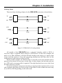
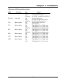
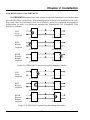
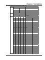
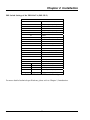
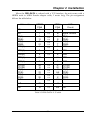
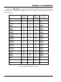
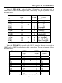
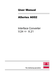
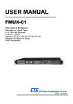
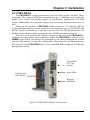
Chapter 2 Installation
2.11 FIB1-DATA
The FIB1-DATA is a high-performance serial over fiber media converter. These
converters fully support Nx64 data transmissions up to 2.048Mbps and completely
handle flow control and clocking signals in synchronous applications over fiber
media. Additionally, the converters support low speed asynchronous connections as
well.
There are five models of FIB1-DATA media converters, V.35, RS-232, RS-530,
X.21, and RS-449 which are based upon three basic hardware types, V.35, RS-232, and
RS-530. The RS-530 hardware is also the source for the X.21 and RS-449 models. All
models require adapter cables to adapt the unit's HDB26 interface connectors.
There are two 8 position DIP switches located on the side of the FIB1-DATA to
configure the units when used standalone. When the FIB1-DATA is placed in the
FRM301 with SNMP, the settings are controlled by the chassis management system
and any DIP settings are ignored. Additionally, when placed in the managed rack,
the remotely linked FIB1-DATA unit is also controlled and configured through the
management system.
Fiber Media
(SC Type
shown)
Status LEDs
Configuration
DIP switches
Datacom
(HDB26F)
Figure 2-12 FIB1-DATA Media Converter Card
27
Chapter 2 Installation
Clocking Modes
There are three clocking schemes for the FIB1-DATA converters, shown below.
TC
TC
RC
RC
Fiber
Int.
Recovery
ETC
TC
RC
Fiber
Ext.
Recovery
RC
ETC
ETC
RC
Fiber
Transparent
Transparent
Figure 2-13 FIB1-DATA Clocking Modes
All models of the FIB1-DATA have a physical interface which is DCE. A
crossover cable is required when acting as a DTE device. In the first example, the
units act as 'Fiber Modems' with the internal clocking unit acting as a master time
source and the remote or loop unit recovering timing from the fiber side. In this
configuration, both units are acting as DCE.
In the second example, an external clock is received at one unit and the clock is
passed to the remote for recovery via the fiber. In this scheme, the left side unit acts
as a DTE and a crossover cable is required. The right hand unit recovers clock from
the fiber and acts as a DCE.
In our last example, transparent clocking is employed; the transmit clock on one
side is used as the source for receive clock on the other. In this scheme the units may
act as DCE or DTE depending on the cable used.
28
Chapter 2 Installation
LED Status LED Detailed Description
LED
PWR
Function
Power indicator
FX Link
Fiber link
Test
Mode display
TD
Mode display
RD
Mode display
RTS
Mode display
CTS
Mode display
DCD
Mode display
State
On
Off
Blinking
On
Off
Blinking
On
Off
On
Off
Blinking
On
Off
Blinking
On
Off
On
Off
On
Off
Status
Converter has power
Converter has no power
No SNMP is installed in FRM301
The fiber link is up
No signal or fiber link is down
Remote side fiber Sync loss
Any loop back test is on
Normal status
"Data Signal" is in "High" state
"Data Signal" is in "Low" state
Normal Data transmitting status
"Data Signal" is in "High" state
"Data Signal" is in "Low" state
Normal Data transmitting status
"Data Signal" is in "High" state
"Data Signal" is in "Low" state
"Data Signal" is in "High" state
"Data Signal" is in "Low" state
"Data Signal" is in "High" state
"Data Signal" is in "Low" state
29
Chapter 2 Installation
Loop Back Features of the FIB1-DATA
The FIB1-DATA features local and remote loop back functions for both the data
port and the fiber connections. When management features are installed in the rack,
loop back may be performed from local console, network connected management
workstation or from a workstation running the Windows® GUI (Graphical User
Interface) software.
LLB
Local
loopback
Local Side
Remote Side
Local Side
Remote Side
Local Side
Remote Side
RLB
Remote
loopback
RRLB
Request
Remote
loopback
Figure 2-14 FIB1-DATA Data Port loop back diagnostic modes
LLB
Local
loopback
Local Side
Remote Side
Local Side
Remote Side
Local Side
Remote Side
RLB
Remote
loopback
RRLB
Request
Remote
loopback
Figure 2-15 FIB1-DATA Optical loop back diagnostic modes
30
Chapter 2 Installation
DIP Switch Settings of the FIB1-DATA (DIP SW 1)
',36:
67$7(
2))
2))
7LPLQJPRGHVHOHFW
7UDQVSDUHQW
21
2))
5HFRYHU\
2))
21
'DWDSRUW
21
21
,QWHUQDORVFLOODWRU
)XQFWLRQ'HVFULSWLRQ
'DWD5DWHJURXSVHWWLQJ
2))
1[.
21
/RZVSHHG
'DWD5DWHVHWWLQJ
1[.
/RZVSHHG
2))
2))
2))
2))
2)) .
21
2))
2))
2))
2)) .
2))
21
2))
2))
2)) .
21
21
2))
2))
2)) .
2))
2))
21
2))
2)) .
21
2))
21
2))
2)) .
2))
21
21
2))
2)) .
21
21
21
2))
2)) .
2))
2))
2))
21
2)) .
21
2))
2))
21
2)) .
2))
21
2))
21
2)) .
21
21
2))
21
2)) .
2))
2))
21
21
2)) .
21
2))
21
21
2)) .
2))
21
21
21
2)) .
21
21
21
21
2)) .
2))
2))
2))
2))
21
.
21
2))
2))
2))
21
.
2))
21
2))
2))
21
.
21
21
2))
2))
21
.
2))
2))
21
2))
21
.
21
2))
21
2))
21
.
2))
21
21
2))
21
.
21
21
21
2))
21
.
2))
2))
2))
21
21
.
21
2))
2))
21
21
.
2))
21
2))
21
21
.
21
21
2))
21
21
.
2))
2))
21
21
21
.
21
2))
21
21
21
.
2))
21
21
21
21
.
21
21
21
21
21
.
$6<1&02'(
Table 2-1 FIB1-DATA, DIP switch 1 setting
31
Chapter 2 Installation
DIP Switch Settings of the FIB1-DATA (DIP SW 2)
',36ZLWFK1XPEHU7DEOH
6ZLWFKDQG6WDWH
)XQFWLRQ'HVFULSWLRQ
'DWDSRUW5&SRODULW\VHWWLQJ
2))
1RUPDO
1
,QYHUWHG
'DWDSRUW7&SRODULW\VHWWLQJ
2))
1RUPDO
1
,QYHUWHG
'DWDSRUW(7&SRODULW\VHWWLQJ
2))
1RUPDO
1
,QYHUWHG
'DWDSRUW576VHWWLQJ
2))
)ROORZ&76
1
$OZD\V21
)DU(QG)DXOW)()6HWWLQJ
2))
'LVDEOHG
21
(QDEOHG
/RRS%DFN6HOHFWLRQ
2))
)LEHU/RRS%DFN
21
'DWD3RUW/RRS%DFN
2))
2))
$OOORRSEDFNRII
/RRSEDFNWHVWVHWWLQJ
21
2))
/RFDO/RRS%DFN//%
2))
21
5HPRWH/RRS%DFN5/%
21
21
5HTXHVW5HPRWH/RRS%DFN55/%
Table 2-2 FIB1-DATA DIP switch 2 setting
For more detailed technical specifications, please refer to Chapter 1, Introduction.
32
Chapter 2 Installation
When the FIB1-DATA is ordered with a V.35 interface, the unit comes with a
HDB26 male to MB34 Female adapter cable, 1 meter long. The pin assignment
follows the table below.
Abbreviation
FG
HDB26
PIN#
1
MB34
V.35
PIN#
Circuit
A
Frame
l
SG
7
l
B
Signal Ground
TD(A)
TD(B)
RD(A)
RD(B)
RTS(A)
2
11
3
21
4
l
l
l
l
l
P
S
R
T
C
TD(A)
TD(B)
RD(A)
RD(B)
RTS
CTS(A)
5
l
D
CTS
DSR(A)
6
l
E
DSR
DTR(A)
20
l
H
DTR
DCD(A)
8
l
F
DCD
ETC(A)
ETC(B)
TC(A)
TC(B)
RC(A)
RC(B)
RLB
24
16
15
23
17
25
9
l
l
l
l
l
l
l
U
W
Y
AA
V
X
HH
ETC(A)
ETC(B)
TC(A)
TC(B)
RC(A)
RC(B)
RL
LLB
18
l
JJ
LL
TM
10
l
KK
TM
Table 2-3 FIB1-DATA V.35 cable
33
Chapter 2 Installation
When the FIB1-DATA is ordered with a RS-530 interface, the unit comes with a
HDB26 male to DB25 Female adapter cable, 1 meter long. The pin assignment follows
the table below.
Abbreviation
FG
HDB26
PIN#
1
DB25
RS-530
PIN#
Circuit
1
Frame
l
SG
7
l
7
AB
TD(A)
TD(B)
RD(A)
RD(B)
RTS(A)
RTS(B)
CTS(A)
CTS(B)
DSR(A)
DSR(B)
DTR(A)
DTR(B)
DCD(A)
DCD(B)
ETC(A)
ETC(B)
TC(A)
TC(B)
RC(A)
RC(B)
RLB
2
11
3
21
4
13
5
14
6
22
20
12
8
26
24
16
15
23
17
25
9
l
l
l
l
l
l
l
l
l
l
l
l
l
l
l
l
l
l
l
l
l
2
14
3
16
4
19
5
13
6
22
20
23
8
10
24
11
15
12
17
9
21
BA(A)
BA(B)
BB(A)
BB(B)
CA(A)
CA(B)
CB(A)
CB(B)
CC(A)
CC(B)
CD(A)
CD(B)
CF(A)
CF(B)
DA(A)
DA(B)
DB(A)
DB(B)
DD(A)
DD(B)
RL
LLB
18
l
18
LL
TM
10
l
25
TM
Table 2-4 FIB1-DATA RS-530 cable
34
Chapter 2 Installation
When the FIB1-DATA is ordered with a RS-449 interface, the unit comes with a
HDB26 male to DB37 Female adapter cable, 1 meter long. The pin assignment follows
the table below.
Abbreviation
FG
HDB26
PIN#
1
l
DB37
RS-449
PIN#
Circuit
1
Frame
SG
7
l
19,20,37 SG,RC,SC
TD(A)
TD(B)
RD(A)
RD(B)
RTS(A)
RTS(B)
CTS(A)
CTS(B)
DSR(A)
DSR(B)
DTR(A)
DTR(B)
DCD(A)
DCD(B)
ETC(A)
ETC(B)
TC(A)
TC(B)
RC(A)
RC(B)
RLB
2
11
3
21
4
13
5
14
6
22
20
12
8
26
24
16
15
23
17
25
9
l
l
l
l
l
l
l
l
l
l
l
l
l
l
l
l
l
l
l
l
l
4
22
6
24
7
25
9
27
11
29
12
30
13
31
17
35
5
23
8
26
14
SD(A)
SD(B)
RD(A)
RD(B)
RS(A)
RS(B)
CS(A)
CS(B)
DM(A)
DM(B)
TR(A)
TR(B)
RR(A)
RR(B)
TT(A)
TT(B)
ST(A)
ST(B)
RT(A)
RT(B)
RL
LLB
18
l
10
LL
TM
10
l
18
TM
Table 2-5 FIB1-DATA RS-449 cable
35
Chapter 2 Installation
When the FIB1-DATA is ordered with a X.21 interface, the unit comes with a
HDB26 male to DB15 Female adapter cable, 1 meter long. The pin assignment follows
the table below.
Abbreviation
FG
SG
TD(A)
TD(B)
RD(A)
RD(B)
RTS(A)
RTS(B)
DCD(A)
DCD(B)
ETC(A)
ETC(B)
RC(A)
RC(B)
HDB26
PIN#
1
7
2
11
3
21
4
13
8
26
24
16
17
25
DB15
PIN#
1
8
2
9
4
11
3
10
5
12
7
14
6
13
l
l
l
l
l
l
l
l
l
l
l
l
X.21
Circuit
Shield
Ground
Transmit(A)
Transmit(B)
Receive(A)
Receive(B)
Control(A)
Control(B)
Indication(A)
Indication(B)
Ext. Timing(A)
Ext. Timing(B)
Signal Timing(A)
Signal Timing(B)
Table 2-6 FIB1-DATA X.21 cable
When the FIB1-DATA is ordered with a RS-232 interface, the unit comes with a
HDB26 male to DB25 Female adapter cable, 1 meter long. The pin assignment follows
the table below.
Abbreviation
FG
SG
TD
RD
RTS
CTS
DSR
DTR
DCD
ETC
TC
RC
HDB26
PIN#
1
7
2
3
4
5
6
20
8
24
15
17
l
l
Å
Æ
l
DB25
PIN#
1
7
2
3
5
6
20
8
24
15
17
Table 2-7 FIB1-DATA RS-232 cable
36
RS-232
Circuit
Frame
SG
TD
RD
RTS
CTS
DSR
DTR
DCD
ETC
TC
RC