1
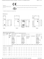
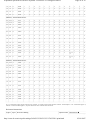
Adjustable Speed Drives & Drive Systems - PowerFlex 70 Configured Drives Page 1 of 22 Catalogs > Drives Catalog > PowerFlex 70 > PowerFlex 70 Configured Drives POWERFLEX 70 CONFIGURED DRIVES Overview This program enhances standalone drive functionality through additional control, power and packaging options which users with special installation needs. The program has two levels: Catalog Configured Drives The Catalog Configured Drives Program allows users to create drive packages based on their specific needs. A comple specified by assembling a single catalog number string that includes a base drive and all required options. Packaging i and 575V requirements in NEMA/UL Type 1 (IP20), NEMA/UL Type 4/12 (IP65) indoor and NEMA/UL Type 3/4 (IP65) ou consists of a fully defined catalog string identified within this price sheet. Focused on higher volume, repeat business provide consistent manufacturing and minimizes customer resources by reducing engineering, manufacturing and inst delivery is 10 business days from order entry and can be ordered through the Passport order entry system. Modified Configured Drives The Modified Configured Drives Program offers users the ability to create drive packages beyond the Catalog Configur Options may or may not be defined within this publication. Product can be ordered by: z z Assembling a catalog string from the options listed in this publication. Engineered options that are listed within this publication will be specified by the heading “Modified Configured and will have varied lead-times. Entering a custom quote request for additional options not listed. A custom quote will require a Passport quote using “SP-SDB-CUSTOM” as the line item part number and enterin base catalog string and custom options in the Competitive Summary. For questions or help with a custom quote Engineered Drives Group at 262-512-8415. Lead Times Lead Times shown on the following pages are based on these codes: Code Description Lead Time (Work Days) P Pre-Engineered (applies to Catalog Configured) 10 Q Quick Turn 20 X Long Lead Time 40 C Custom 60 Dependent on options selected. Catalog Number Explanation To interpret the meaning of a catalog number, match the values of the catalog number code in positions a, b, c, etc. b, c, etc. below. 21A B 9P6 A 3 A Y N A R C 0 NN NN -ND http://www.ab.com/en/epub/catalogs/36265/1323285/1323317/4355911/print.html 03/01/2007 Adjustable Speed Drives & Drive Systems - PowerFlex 70 Configured Drives Page 2 of 22 a b c d e f g h i j k l m n o a Drive Code Type 21A PowerFlex 70 Configured b Voltage Rating Code Voltage Lead Time X 208V ac X B 240V ac P D 480V ac P E 600V ac P c1 Amp Rating 208V, 60Hz Input Code Amps kW (Hp) 2P2 2.5 0.37 (0.5) 4P2 4.8 0.75 (1.0) 6P8 7.8 1.5 (2.0) 9P6 11 2.2 (3.0) 015 17.5 4.0 (5.0) 022 25.3 5.5 (7.5) 028 32.2 7.5 (10) 042 43 11 (15) 054 62.1 15 (20) 070 78.2 18.5 (25) Maximum continuous rating for normal duty drives. c2 Amp Rating 240V, 60Hz Input Code Amps kW (Hp) 2P2 2.2 0.37 (0.5) 4P2 4.2 0.75 (1.0) 6P8 6.8 1.5 (2.0) 9P6 9.6 2.2 (3.0) 015 15.3 4.0 (5.0) 022 22 5.5 (7.5) 028 28 7.5 (10) 042 42 11 (15) 054 54 15 (20) http://www.ab.com/en/epub/catalogs/36265/1323285/1323317/4355911/print.html 03/01/2007 Adjustable Speed Drives & Drive Systems - PowerFlex 70 Configured Drives 070 70 Page 3 of 22 18.5 (25) Maximum continuous rating for normal duty drives. c3 Amp Rating 600V, 60Hz Input Code Amps kW (Hp) 0P9 0.9 0.37 (0.5) 1P7 1.7 0.75 (1.0) 2P7 2.7 1.5 (2.0) 3P9 3.9 2.2 (3.0) 6P1 6.1 4.0 (5.0) 9P0 9.0 5.5 (7.5) 011 11 7.5 (10) 017 17 11 (15) 022 22 15 (20) 027 27 18.5 (25) 032 32 22 (30) 041 41 30 (40) 052 52 37 (50) Maximum continuous rating for normal duty drives. d Enclosure Type Code Enclosure A NEMA/UL Type 1/IP20 D NEMA/UL Type 4 Indoor E NEMA/UL Type 4 Outdoor G NEMA/UL Type 12 Indoor e HIM Code Version 0 No HIM - Blank Plastic Inserted (Drive Mounted) 2 Digital LCD HIM (Drive Mounted) 3 Full Numeric LCD HIM (Drive Mounted) 5 Programmer Only LCD HIM (Drive Mounted) A Drive Mounted LCD Full Numeric & Door Mounted Bezel w/Blank Cover, NEMA/UL Type 1 B Drive Mounted LCD Full Numeric & Door Mounted Bezel w/LCD Digital Speed, NEMA/UL Type 1 C Door Mounted Bezel w/LCD Full Numeric, NEMA/UL Type 1 E Drive Mounted LCD Full numeric & Door Mounted Bezel w/LCD Programmer Only, NEMA/UL Type 1 F Drive Mounted LCD Full Numeric & Door Mounted LCD Full Numeric, NEMA/UL Type 1/12 G Drive Mounted LCD Full Numeric & Door Mounted Programmer Only, NEMA/UL Type 1/12 L Door Mounted NEMA/UL Type 1/12 Bezel, No HIM, Blank Cover Inserted, NEMA/UL Type 1/12 http://www.ab.com/en/epub/catalogs/36265/1323285/1323317/4355911/print.html 03/01/2007 Adjustable Speed Drives & Drive Systems - PowerFlex 70 Configured Drives J Door Mounted Full Numeric LCD HIM, NEMA/UL Type 1/12 K Door Mounted NEMA/UL Type 1/12 Programmer Only Page 4 of 22 f Documentation Code Type Lead Time A English User Manual and Multi-Language Quick Start P N No Manual P g Brake Code w/Brake IGBT Lead Time Y Yes P h Brake Resistor Code w/Resistor Lead Time Y Yes (Internal) P N No P i Emission Class Code Rating A Filtered A7 & B Frames (Optional) C, D, & E Frames (Standard) N Not Filtered A & B Frames (Optional) C, D, & E Frames 600V Frames A through D available only without filter (Cat. Code N). 600V Frame E available only with filter (Cat. Code A). 7 Increases size to Frame B. j Comm Slot Code Version Lead Time N None P C ControlNet (Coax) P D DeviceNet P E EtherNet P H RS485 HVAC P I Interbus P L LonWorks P P PROFIBUS P Q ControlNet (Fiber) P R RIO P S RS485 DF-1 P http://www.ab.com/en/epub/catalogs/36265/1323285/1323317/4355911/print.html 03/01/2007 Adjustable Speed Drives & Drive Systems - PowerFlex 70 Configured Drives Page 5 of 22 k I/O Code Control I/O Volts Lead Time C Enhanced 24V dc P D Enhanced 115V ac P l Feedback Code Type Lead Time 0 None P 1 Encoder, 5/12V P m Code Rating NN Lead Time Reserved P n Code Rating Lead Time NN None P o Options (as required) Code Description Lead Time ND Normal Duty P HD Heavy Duty P B0 No Bypass P B2/B527 Automatic Bypass P B5/B557 Manual Bypass P C1 Drive Only Control Power P C5 Customer Supplied Control Power P J1 Control Power On Aux. Contact P J2 Drive Fault Auxiliary Contact P J3 Alarm Auxiliary Contact P J4 Drive Run Auxiliary Contact P J5 At Speed Auxiliary Contact P J8/J587 Motor Heater Control P L1 3% Input Line Reactor P L2 3% Output Line Reactor P L6, L7, L8 Input Filter X M3 Drive/Bypass Motor Run Time Meter P N1 Iso. Analog Input - 0-10V dc P N2 Iso. Analog Input - 4-20 mA P N3 Iso. Analog Output - 0-10V dc P http://www.ab.com/en/epub/catalogs/36265/1323285/1323317/4355911/print.html 03/01/2007 Adjustable Speed Drives & Drive Systems - PowerFlex 70 Configured Drives Page 6 of 22 N5 Building Management Control Interface P P1 No Input Protection P P2 Drive Input Fuses P P3 Drive Breaker P P4 Drive Bypass Mode Breaker P P6 Drive Disconnect Switch, Fused P P7 Drive Bypass Mode, Fused Disconnect P P11 Drive Input Contactor P P12 Drive Output Contactor P S1/S517 Hand/Off/Auto S.S. (Start/Stop/Speed Ref) P S9/S597 Run PL P S10/S607 Drive Fault PL P S11/S617 At Speed PL P S12/S627 Drive Alarm PL P S13/S637 Control Power On PL P S14/S647 Drive Mode P.I. & Bypass Mode PL P S15/S657 Bypass Mode PL & Auto Bypass Enable PL P S16/S667 Drive Disable Mushroom PB P S17/S677 Motor Fault PL P S18/S687 Analog Potentiometer P 7 Denotes 800F/800T device. When selecting multiple options, Do Not combine 800F and 800T devices (all devices must be the sa Catalog Configured Drives Program How to Order a Catalog Configured Drive z z Step 1. Select the basic PowerFlex 70 drive catalog number based on application requirements (i.e. nominal H cycle). Step 2. Specify Options – The following pages list and describe the available options. The listing is divided into assist in quickly locating specific needs. Some options are horsepower and/or voltage specific, or will have spe them – Read all footnotes. Example: An application requires a variable speed control for an existing 3 Hp, 480V, normal duty, AC conveyor moto will be located in a clean environment. Local control is required on the door for programming, start, stop, speed and across the line (with selection and mode indication at drive) is required. A system disconnect switch should be availab required. Description Cat. No./Option Code Position Basic Drive w/IP 20 (NEMA/UL Type 1 Enclosure) 21AD5P0A 1…8 Human Interface Module - LCD (Drive Mounted) 3 9 User Manual A 10 w/Brake IGBT Y 11 No Brake Resistor N 12 Not Filtered N 13 No Communication Module N 14 115V Enhanced Control D 15 http://www.ab.com/en/epub/catalogs/36265/1323285/1323317/4355911/print.html 03/01/2007 Adjustable Speed Drives & Drive Systems - PowerFlex 70 Configured Drives No Feedback Option 0 16 Reserved for Future Options NN 17…18 Special Options NN 19…20 Normal Duty -ND 22…23 Bypass, Manual with D/O/B Switch -B5 Control Power -C1 Drive/Bypass Fused Disconnect Switch -P7 Drive & Bypass Mode Pilot Lights -S14 "Drive Disable" Pushbutton -S16 21AD5P0ACAYNNND0NNNN-ND-B5-C1-P7-S14-S16 Page 7 of 22 Product Selection Build a Catalog Number 208…240V ac, Three-Phase Drives Output Amps Nominal Power Ratings Frame Size IP20, NEMA/UL Type 1 IP65, NEMA/UL Type IP65, NEMA/UL Typ 4 Indoor 4 Outdoor 208…240V ac Input Normal Duty Heavy Duty Cat. No. Cat. No. Cat. No. Cont. 1 Min. 3 Sec. kW Hp kW Hp 21A… 21A… 21A… 0.9 1.0 1.4 0.37 0.5 0.25 0.33 A B2P2A B2P2D B2P2E 1.7 1.9 2.6 0.75 1.0 0.55 0.75 A B4P2A B4P2D B4P2E 2.7 3.6 4.8 1.5 2.0 1.1 1.0 B B6P8A B6P8D B6P8E 3.9 4.3 5.8 2.2 3.0 1.5 1.5 B B9P6A B9P6D B9P6E 6.1 6.7 9.1 4.0 5.0 3.0 3.0 C B015A B015D B015E 9.0 9.9 13.5 5.5 7.5 4.0 5.0 D B022A B022D B022E 11 13.5 18 7.5 10 5.5 7.5 D B028A B028D B028E 17 18.7 25.5 11 15 7.5 10 D B042A B042D B042E 22 25.5 34 15 20 11 15 E B054A B054D B054E 27 33 44 18.5 25 15 20 E B070A B070D B070E For 208V replace Code B with Code X. B2P2A = 240V and X2P2A = 208V 480V ac, Three-Phase Drives Output Amps Nominal Power Ratings 480V ac Input Normal Duty Frame Size IP20, NEMA/UL Type 1 IP65, NEMA/UL Type IP65, NEMA/UL Typ 4 Indoor 4 Outdoor Heavy Duty Cat. No. Cat. No. Cat. No. 21A… 21A… 21A… Cont. 1 Min. 3 Sec. kW Hp kW Hp 1.1 1.2 1.6 0.37 0.5 0.25 0.33 A D1P1A D1P1D D1P1E 2.1 2.4 3.2 0.75 1.0 0.55 0.75 A D2P1A D2P1D D2P1E 3.4 4.5 6.0 1.5 2.0 1.1 1.5 A D3P4A D3P4D D3P4E 5.0 5.5 7.5 2.2 3.0 1.5 2.0 B D5P0A D5P0D D5P0E http://www.ab.com/en/epub/catalogs/36265/1323285/1323317/4355911/print.html 03/01/2007 Adjustable Speed Drives & Drive Systems - PowerFlex 70 Configured Drives Page 8 of 22 8.0 8.8 12 4.0 5.0 3.0 3.0 B D8P0A D8P0D D8P0E 11 12.1 16.5 5.5 7.5 4.0 5.0 C D011A D011D D011E 14 16.5 22 7.5 10 5.5 7.5 C D014A D014D D014E 22 24.2 33 11 15 7.5 10 D D022A D022D D022E 27 33 44 15 20 11 15 D D027A D027D D027E 34 40.5 54 18.5 25 15 20 D D034A D034D D034E 40 51 68 22 30 18.5 25 D D040A D040D D040E 52 60 80 30 40 22 30 E D052A D052D D052E 65 78 104 37 50 30 40 E D065A D065D D065E Frame Size IP20, NEMA/UL Type 1 IP65, NEMA/UL Type IP65, NEMA/UL Typ 4 Indoor 4 Outdoor 600V ac, Three-Phase Drives Output Amps Nominal Power Ratings 600V ac Input Normal Duty Heavy Duty Cat. No. Cat. No. Cat. No. 21A… 21A… 21A… Cont. 1 Min. 3 Sec. kW Hp kW Hp 0.9 1.0 1.4 0.37 0.5 0.25 0.33 A E0P9A E0P9D E0P9E 1.7 1.9 2.6 0.75 1.0 0.55 0.75 A E1P7A E1P7D E1P7E 2.7 3.6 4.8 1.5 2.0 1.1 1.0 A E2P7A E2P7D E2P7E 3.9 4.3 5.8 2.2 3.0 1.5 1.5 B E3P9A E3P9D E3P9E 6.1 6.7 9.1 4.0 5.0 3.0 3.0 B E6P1A E6P1D E6P1E 9.0 9.9 13.5 5.5 7.5 4.0 5.0 C E9P0A E9P0D E9P0E 11 13.5 18 7.5 10 5.5 7.5 C E011A E011D E011E 17 18.7 25.5 11 15 7.5 10 D E017A E017D E017E 22 25.5 34 15 20 11 15 D E022A E022D E022E 27 33 44 18.5 25 15 20 D E027A E027D E027E 32 40.5 54 22 30 18.5 25 D E032A E032D E032E 41 48 64 30 40 22 30 E E041A E041D E041E 52 61.5 82 37 50 30 40 E E052A E052D E052E Factory Installed Options Human Interface Modules (HIM) - Position e Catalog Code: 0 Drive Mounted Blank Cover No HIM Catalog Code: 2 Drive Mounted LCD Digital Speed Catalog Code: 3 Drive Mounted LCD Full Numeric Catalog Code: C Door Mounted Beze Full Numeric (NEMA http://www.ab.com/en/epub/catalogs/36265/1323285/1323317/4355911/print.html 03/01/2007 Adjustable Speed Drives & Drive Systems - PowerFlex 70 Configured Drives Page 9 of 22 Catalog Code: 5 Drive Mounted LCD Programmer Only Catalog Code: J Door Mounted LCD Full Numeric (NEMA/UL Type 12) Catalog Code: L Door Mounted Bezel w/Blank Cover (NEMA/UL Type 1) Catalog Code: K Door Mounted Prog Only (NEMA/UL Typ Catalog Code: A Catalog Code: B Drive Mounted LCD Full Drive Mounted LCD Full Numeric & Door Mounted Numeric & Bezel w/LCD Digital Speed (NEMA/UL Type 1) Door Mounted Bezel w/Blank Cover (NEMA/UL Type 1) Catalog Code: E Catalog Code: F Drive Mounted LCD Full Numeric Drive Mounted LCD & Door Mounted Bezel w/LCD LCD Full Numeric (N Programmer Only (NEMA/UL Type 1) Catalog Code: G Drive Mounted LCD Full Numeric & Door Mounted Programmer Only (NEMA/UL Type 12) NEMA/UL Type 12 HIMs can be substituted for NEMA/UL Type 1 to eliminate the removable HIM feature. Documentation Description Cat. Code Lead Time (Position f) User Manual (Standard) A P Internal Brake IGBT Frame Cat. Code Lead Time (Position g) A…E Y P http://www.ab.com/en/epub/catalogs/36265/1323285/1323317/4355911/print.html 03/01/2007 Adjustable Speed Drives & Drive Systems - PowerFlex 70 Configured Drives Page 10 of 22 Small Duty Internal Dynamic Brake Resistors These resistors have a limited duty cycle. Refer to the PowerFlex Dynamic Braking Selection Guide to determine if an sufficient for your application. An external resistor may be required. See Small Duty Internal Dynamic Brake Resistors Drive Input Voltage Frame Brake Resistance Cat. Code 208/240V ac 480V ac 600V ac Lead Time Ω (Position h) A…E – N P A 62 Y P B 62 Y P C 62 Y P D 22 Y P E Not Available N P A…E – N P A 115 Y P B 115 Y P C 115 Y P D 62 Y P E Not Available N P A…E – N P A 115 Y P B 115 Y P C 115 Y P D&E Not Available N P Internal EMC Filter § Drive Input Voltage Frame CE Filter Cat. Code (Position i) 208/240V ac 480V ac 600V ac A No N B No N Yes A C Yes A D Yes A E Yes A A No N B No N Yes A C Yes A D Yes A E Yes A A…D Not Available N E Yes A http://www.ab.com/en/epub/catalogs/36265/1323285/1323317/4355911/print.html 03/01/2007 Adjustable Speed Drives & Drive Systems - PowerFlex 70 Configured Drives Page 11 of 22 § Internal CE filters are not available for PowerFlex 70 Frame A drives. If a Frame A rating is ordered with an internal filter option Frame B. ‡ Lead Time = X for 208V ac. Internal Communication Adapters Description Cat. Code Lead Time (Position j) BACnet® MS/TP RS-485 Communication Adapter B P ControlNet™ Communication Adapter (Coax) C P DeviceNet™ Communication Adapter D P EtherNet/IP™ Communication Adapter E P HVAC Communication Adapter H P Interbus™ Communication Adapter I P LonWorks™ Communication Adapter L P None N P PROFIBUS™ DP Communication Adapter P P ControlNet Communication Adapter (Fiber) Q P Remote I/O Communication Adapter R P RS-485 DF1 Communication Adapter S P I/O Options Cat. Code Description (One Required) Lead Time (Position k) Enhanced 24V dc 7 C P Enhanced 115V ac 7 ♣ D P Drive input interface only. Other configured options may require option -C1 or -C5, user supplied 115V. 7 Enhanced Control option utilizes DPI Only. ♣ 115V control uses 24V I/O plus 115V Interface Card. Feedback Options (Enhanced Control Only) Description (One Required) Cat. Code Lead Time (Position l) No Encoder 0 (Std) P Encoder Feedback 1 P Reserved/Special Options Description (One Required) Cat. Code Lead Time (Position m) (Position n) No Special Option NN NN P Suggested Power Distribution Schemes http://www.ab.com/en/epub/catalogs/36265/1323285/1323317/4355911/print.html 03/01/2007 Adjustable Speed Drives & Drive Systems - PowerFlex 70 Configured Drives Page 12 of 22 Power Disconnecting Means http://www.ab.com/en/epub/catalogs/36265/1323285/1323317/4355911/print.html 03/01/2007 Adjustable Speed Drives & Drive Systems - PowerFlex 70 Configured Drives Page 13 of 22 Important: Customer must select one of the following; -P1, P2, P3, P4, P6 or -P7. If option -P1 is selected, power disc drive branch circuit protection must be supplied by user. Description Option Code Lead Time No Input Protection -P1 P ‡ Drive Input Fuses -P2 P ‡ Drive Breaker -P3 P ‡ Drive Bypass Mode, Breaker -P4 7 P ‡ Drive Disconnect Switch, Fuses -P6 P ‡ Drive Bypass Mode, Fuses, Disconnect -P7 7 P ‡ This option can not be used with Bypass. 7 This option must be used in conjunction with a Bypass Option. ‡ Lead Time = X for 208V ac. Power and Bypass Options Description Option Code Lead Time Contactor, Drive Input -P11 ♣ P ‡ Contactor, Drive Output -P12 7 ♣ P ‡ No Bypass Required -B0 ¾ P ‡ Manual Bypass -B5/B55 ♣ ¾ a P ‡ Automatic Bypass -B2/B52 § a P ‡ An output contactor may not be chosen when Bypass is selected. 7 This option must be used in conjunction with the Auxiliary Fault Contact option -J2. ‡ Lead Time = X for 208V ac. § Option includes “Drive-Off-Bypass” selector switch and must be used in conjunction with the Auxiliary Fault Contact option (-J2) ♣ Requires option -C1 or user supplied 115V (option -C5). ¾ B0 or B5 must be selected. a Includes a Class 10 Adjustable Thermal Overload Relay that does not require separate heater elements. Control Power, 3% Line Reactor and Harmonic Filter Options Description Option Code Lead Time 115V Control Power, Drive/Options Only -C1 P ‡ 115V Control Power, User Supplied -C5 P ‡ 3% Input Line Reactor Mounted in Enclosure -L1 P ‡ 3% Output Line Reactor Mounted in Enclosure -L2 P ‡ Input Filter -L6, L7, L8 7 X C1 or C5 must be selected. 7 480V ac Only. These options will increase enclosure size. Consult factory for details. ‡ Lead Time = X for 208V ac. Descriptions for L6, L7 & L8 follow, note that these options will incease enclosure size. Consult factory for details. z L6 Harmonic Filter - This option is used to reduce harmonic current and voltage distortion at the AC line. This o compliance with the harmonic distortion limits and requirements set forth in IEEE519-1992. Sometimes known http://www.ab.com/en/epub/catalogs/36265/1323285/1323317/4355911/print.html 03/01/2007 Adjustable Speed Drives & Drive Systems - PowerFlex 70 Configured Drives z z Page 14 of 22 consists of a tuned LC (inductor capacitor) network and buffering reactor employed as an integral harmonic inp harmonic distortion is very dependent on system parameters. Typical voltage distortion limits will be less than distortion varying based on the system source impedance. L7 Harmonic Filter with Capacitor Contactor - In addition to the L6 option, the L7 option includes a dropout co tuned LC network portion of the filter when the drive is not running (input line reactor portion of the filter wil Disengaging the LC network will reduce or eliminate leading power factor conditions that might exist under low feature is especially useful on larger drive filter installations. L8 Harmonic Filter with Adjustable Capacitor Contactor - In addition to the L6 option, the L8 option includes a disengage the tuned LC network portion of the filter when the drive is running at a lightly loaded condition (in the filter will still be in place). Disengaging the LC network will reduce or eliminate leading power factor cond under low power operation. This feature allows adjustment of the drop out point to be adjusted between appr the input current with a small hysteresis band of about 5% to prevent contactor chatter. This option is especial filter installations and is recommended for use on back up generator installations. Technical Information for Thermal Overload Relays Class 10 (Bulletin 193-T) Relays: z z z z Will trip in 10 seconds or less at 600% of device current rating. Trip setting is adjustable per the range chart shown. Range is chosen to cover the NEC motor circuit for the horsepower selected. If a motor outside the published adjustability range is to be used - enter customer order and provide complete 208…240V AC, Three-Phase Drives Drive Rating ND Hp Drive Rating HD Hp Class 10 Adjustable Thermal Overload Relay Adjustable Range (Amps) Normal Duty Heavy Duty 208V 240V 208/240V 0.5 0.33 2.4…4.0 1.6…2.4 1.6…2.4 1.0 0.75 4.0…6.0 4.0…6.0 2.4…4.0 2.0 1.5 6.0…10 6.0…10 4.0…6.0 3.0 2.0 10…16 10…16 6.0…10 5.0 3.0 16…24 16…24 6.0…10 7.5 5.0 18…30 18…30 10…16 10 7.5 30…45 30…45 18…30 15 10 30…45 30…45 18…30 20 15 45…60 45…60 30…45 25 20 60…75 60…75 45…60 480V AC, Three-Phase Drives Drive Rating ND Hp Drive Rating HD Hp Class 10 Adjustable Thermal Overload Relay Adjustable Range (Amps) Normal Duty Heavy Duty 0.5 0.33 1.0…1.6 0.6…1.0 1.0 0.75 1.6…2.4 1.6…2.4 2.0 1.5 2.4…4.0 2.4…4.0 3.0 2.0 4.0…6.0 2.4…4.0 http://www.ab.com/en/epub/catalogs/36265/1323285/1323317/4355911/print.html 03/01/2007 Adjustable Speed Drives & Drive Systems - PowerFlex 70 Configured Drives 5.0 3.0 6.0…10 4.0…6.0 7.5 5.0 10…16 6.0…10 10 7.5 10…16 10…16 15 10 16…24 10…16 20 15 18…30 18…30 25 20 30…45 18…30 30 25 30…45 30…45 40 30 45…60 30…45 50 40 60…75 45…60 Page 15 of 22 600V AC, Three-Phase Drives Drive Rating ND Hp Drive Rating HD Hp Class 10 Adjustable Thermal Overload Relay Adjustable Range (Amps) Normal Duty Heavy Duty 0.5 0.33 1.6…2.4 1.0…1.6 1.0 0.75 1.6…2.4 1.0…1.6 2.0 1.5 2.4…4.0 1.6…2.4 3.0 2.0 2.4…4.0 2.4…4.0 5.0 3.0 6.0…10 4.0…6.0 7.5 5.0 6.0…10 6.0…10 10 7.5 10…16 10…16 15 10 16…24 16…24 20 15 16…24 16…24 25 20 16…24 16…24 30 25 30…45 16…24 40 30 30…45 30…45 50 40 45…60 30…45 Control Interface & Feedback Options Description Option Code Lead Time Analog Inputs/Outputs Isolated Analog Input, 0-10V dc -N1 7 P Isolated Analog Input, 4-20 mA -N2 7 P Isolated Analog Output, 0-10V dc -N3 7 P -J1 7 P Control Relay Option Control Power On Auxiliary Contacts, (2) Form C 2-N.O., 2-N.C. Drive Fault -J2 7 P Alarm -J3 7 P Drive Run -J4 7 P At Speed -J5 7 P Programmable Relay A -J6 7 P Programmable Relay B -J7 7 P http://www.ab.com/en/epub/catalogs/36265/1323285/1323317/4355911/print.html 03/01/2007 Adjustable Speed Drives & Drive Systems - PowerFlex 70 Configured Drives Building Management Control Interface -N5 7 Page 16 of 22 P Maximum of two drive digital options can be selected. NOTE: S9 + J4 = One Digital Output S10 + J2 = One Digital Output S11 + J5 = One Digital Output S12 + J3 = One Digital Output All other combinations = One Digital Output. 7 This requires option -C1 or user supplied 115V (option -C5). Motor Interface Options Description Option Code ‡ Lead Time Motor Heater Control -J8/J58 ‡ P ‡ Requires user supplied control power. ‡ 800F/800T device. When selecting multiple options, Do Not combine 800F and 800T devices (all devices must be the same type). Operator Devices - Door Mounted Description Option Code ‡ Lead Time H/O/A S.S. (Start/Stop/Spd. Ref.) -S1/S51 a P Run Pilot Light -S9/S59 7 P Drive Fault Pilot Light -S10/S60 7 P At Speed Pilot Light -S11/S61 7 P Drive Alarm Pilot Light -S12/S62 7 P Control Power On Pilot Light -S13/S63 7 P Drive & Bypass Mode Pilot Lights -S14S64 7 ♣ P Bypass Mode & Auto Bypass En. P.L. -S15/S65 7 ¾ P Drive Disable Mushroom P.B. -S16/S66 a P Motor Fault Pilot Light -S17/S67 7 ♣ P Analog Potentiometer -S18/S68 P Maximum of two drive digital options can be selected. NOTE: S9 + J4 = One Digital Output S10 + J2 = One Digital Output S11 + J5 = One Digital Output S12 + J3 = One Digital Output All other combinations = One Digital Output. 7 This requires option -C1 or user supplied 115V (option -C5). ‡ 800F/800T device. When selecting multiple options, Do Not combine 800F and 800T devices (all devices must be the same type). ♣ Option available when -B5/B55 is selected. ¾ Option available when -B2/B52 is selected. a Requires option -C1 or -C5 if 115V ac interface is selected. Cannot be used with -N1 or -N3 options. Meters - Door Mounted Description Option Code Lead Time Drive/Bypass Motor Run Time Meter (Elapsed Hours) Non-Resettable -M3 7 P 7 This requires option -C1 or user supplied 115V (option -C5). Codes and Standards Code/Standard CE (European Conformance Standard) Action Consult the factory with requirements to meet the separate Low Voltage and/or EMC direc http://www.ab.com/en/epub/catalogs/36265/1323285/1323317/4355911/print.html 03/01/2007 Adjustable Speed Drives & Drive Systems - PowerFlex 70 Configured Drives IEEE519 (Harmonic Distortion Levels) Page 17 of 22 Provide a one-line power distribution drawing, and the associated specification to the fact UL, c-UL This program provides UL panel recognition from the factory as standard. Modified Configured Drives Program Only Enclosures Maximum Enclosure Dimensions Ratings ND Hp HD Hp Drive Power Enclosure Style for Flange Mounted Drives Frame Flex NEMA/UL Type 1, NEMA/UL Type 12 & 4 Indoor, Size 70 Option Code A Option Code D/G Flange Drive B0, C1, C5, All Options B0, C1, C5, All options Cat. S1/S51, S1/S51, Less Line No. S9/S59… S9/S59… Reactor S13/S63, S13/S63, S16/S66, S16/S66, P1…P3 or P1…P3 or P6, Drive P6, Drive Mounted Mounted Options & Options & All HIMs All HIMs NEMA/UL Type 4 Out Option Code E All Options B0, C1, C5, Al S1/S51, Le S9/S59… Re S13/S63, S16/S66, P1…P3 or P6 & Drive Mounted Options & All HIMs Figure Style Figure Style Figure Style Figure Style Figure Style Figure Style Fig 230V ac, Three-Phase Drives 0.5 0.33 A B2P2 1 1 2 3 1 1 2 3 2 3 1 1 2 1.0 0.75 A B4P2 1 1 2 3 1 1 2 3 2 3 1 1 2 2.0 1.5 B B6P8 1 1 2 3 1 1 2 3 2 4 1 1 2 3.0 2.0 B B9P6 1 1 2 3 1 1 2 3 2 4 1 1 2 5.0 3.0 C B015 1 1 2 3 1 1 2 3 2 4 1 1 2 7.5 5.0 D B022 1 1 2 4 1 1 2 4 2 4 1 1 2 http://www.ab.com/en/epub/catalogs/36265/1323285/1323317/4355911/print.html 03/01/2007 Adjustable Speed Drives & Drive Systems - PowerFlex 70 Configured Drives Page 18 of 22 10 7.5 D B028 1 1 2 4 1 1 2 4 2 5 1 1 2 15 10 D B042 1 1 2 4 1 1 2 4 2 5 1 1 2 20 15 E B054 1 2 2 6 1 2 2 6 2 6 1 2 2 25 20 E B070 1 2 2 6 1 2 2 6 2 6 1 2 2 480V ac, Three-Phase Drives 0.5 0.33 A D1P1 1 1 2 3 1 1 2 3 2 3 1 1 2 1.0 0.75 A D2P1 1 1 2 3 1 1 2 3 2 3 1 1 2 2.0 1.5 A D3P4 1 1 2 3 1 1 2 3 2 3 1 1 2 3.0 2.0 B D5P0 1 1 2 3 1 1 2 3 2 4 1 1 2 5.0 3.0 B D8P0 1 1 2 3 1 1 2 3 2 4 1 1 2 7.5 5.0 C D011 1 1 2 3 1 1 2 3 2 4 1 1 2 10 7.5 C D014 1 1 2 3 1 1 2 3 2 4 1 1 2 15 10 D D022 1 1 2 4 1 1 2 4 2 5 1 1 2 20 15 D D027 1 1 2 4 1 1 2 4 2 5 1 1 2 25 20 D D034 1 1 2 4 1 1 2 4 2 5 1 1 2 30 25 D D040 1 1 2 4 1 1 2 4 2 5 1 1 2 40 30 E D052 1 2 2 6 1 2 2 6 2 6 or 7 1 2 2 50 40 E D065 1 2 2 6 1 2 2 6 2 6 or 7 1 2 2 600V ac, Three-Phase Drives 0.5 0.33 A E0P9 1 1 2 3 1 1 2 3 2 3 1 1 2 1.0 0.75 A E1P7 1 1 2 3 1 1 2 3 2 3 1 1 2 2.0 1.5 A E2P7 1 1 2 3 1 1 2 3 2 3 1 1 2 3.0 2.0 B E3P9 1 1 2 3 1 1 2 3 2 4 1 1 2 5.0 3.0 B E6P1 1 1 2 3 1 1 2 3 2 4 1 1 2 7.5 5.0 C E9P0 1 1 2 3 1 1 2 3 2 4 1 1 2 10 7.5 C E011 1 1 2 3 1 1 2 3 2 4 1 1 2 15 10 D E017 1 1 2 4 1 1 2 4 2 4 1 1 2 20 15 D E022 1 1 2 4 1 1 2 4 2 5 1 1 2 25 20 D E027 1 1 2 4 1 1 2 4 2 5 1 1 2 30 25 D E032 1 1 2 4 1 1 2 4 2 5 1 1 2 40 30 E E041 1 2 2 6 1 2 2 6 2 6 1 2 2 50 40 E E052 1 2 2 6 1 2 2 6 2 6 or 7 1 2 2 x or x denotes Figure/Style with one line reactor "or" Figure/Style with two line reators. For Example: "2 or 3" denotes Figure 2, reactor is selected and Figure 3, Style 8 when two line reactors are selected. Enclosure Dimensions Figure Style Enclosure Rating Option Code http://www.ab.com/en/epub/catalogs/36265/1323285/1323317/4355911/print.html Dimensions 7 03/01/2007 Adjustable Speed Drives & Drive Systems - PowerFlex 70 Configured Drives Page 19 of 22 (Position d) H x W x D (mm) H 1 1 NEMA/UL Type 1 A 812.8 x 330.2 x 484.1 32 1 2 NEMA/UL Type 1 A 1,270.0 x 406.4 x 484.1 50 2 3 NEMA/UL Type 1 A 812.8 x 609.6 x 484.1 32 2 4 NEMA/UL Type 1 A 965.2 x 609.6 x 484.1 38 2 6 NEMA/UL Type 1 A 1,270.0 x 762.0 x 484.1 50 1 1 NEMA/UL Type 4/12 for Indoor use, NEMA/UL Type 4 for Outdoor use D or E 812.8 x 330.2 x 484.1 32 1 2 NEMA/UL Type 4/12 for Indoor use, NEMA/UL Type 4 for Outdoor use D or E 1,270.0 x 406.4 x 484.1 50 2 3 NEMA/UL Type 4/12 for Indoor use, NEMA/UL Type 4 for Outdoor use D or E 812.8 x 609.6 x 484.1 32 2 4 NEMA/UL Type 4/12 for Indoor use, NEMA/UL Type 4 for Outdoor use D or E 965.2 x 609.6 x 484.1 38 2 5 NEMA/UL Type 4/12 for Indoor use, NEMA/UL Type 4 for Outdoor use D or E 1,270.0 x 609.6 x 484.1 50 2 6 NEMA/UL Type 4/12 for Indoor use, NEMA/UL Type 4 for Outdoor use D or E 1,270.0 x 762.0 x 484.1 50 2 7 NEMA/UL Type 4/12 for Indoor use, NEMA/UL Type 4 for Outdoor use D or E 1,270.0 x 914.4 x 484.1 50 3 8 NEMA/UL Type 4/12 for Indoor use, NEMA/UL Type 4 for Outdoor use D or E 812.8 x 831.9 x 484.1 50 3 9 NEMA/UL Type 4/12 for Indoor use, NEMA/UL Type 4 for Outdoor use D or E 1,270.0 x 984.3 x 484.1 50 7 Depth includes 6.35 mm (2.5 in) for Operator Handle when ordered. Options L6, L7 & L8 will increase enclosure size. Consult fa Drawing and Test Options (For Configured Drives Only) Description — One Set of... Manufacturing Drawings 279 x 432 mm (11 x 17 in.) One set of schematics — “Information Only - Manufacture Proceeding” Not to be used as Approval Drawings Diskette Electronic Drawings Black & Whites Vellums Final Drawings (as shipped) 279 x 432 mm (11 x 17 in.) One set of schematics — “Copy of Drawings that Shipped with the Job” Diskette Electronic Drawings Black & Whites Vellums Mylar Test Report, Drive Only Modified Configured Drives Program Only Approval Drawings 279 x 432 mm (11 x 17 in.) One set of schematics — “Manufacture Held Until Approved Prints are Received” Diskette Electronic Drawings Black & Whites Vellums As Commissioned Drawings 279 x 432 mm (11 x 17 in.) One set of schematics — “Provided after Field Changes are Returned to the Factory” http://www.ab.com/en/epub/catalogs/36265/1323285/1323317/4355911/print.html 03/01/2007 Adjustable Speed Drives & Drive Systems - PowerFlex 70 Configured Drives Page 20 of 22 Black & Whites Certified Motor Dimension Drawing Disk Copy of "Final As Shipped" Schematics (Autocad 2000) Basic Harmonic Analysis - Pre-order review of customer’s one line power distribution diagram. Complete Harmonic Analysis - Post-order detailed harmonic spectrum analysis and a written report. Deluxe Harmonic Analysis - Post-order site verification of actual harmonics, detailed spectrum analysis and a detailed written report. Witness Test, User Viewing of Rockwell Automation Standard Test Procedures ‡ Includes viewing Rockwell Automation standard test only. Any special requirements must be reviewed by Rockwell Automation fo price changes. Option Selection Reference Guide Required Options z z z z Normal Duty or Heavy Duty Power Input or Disconnecting Means Bypass or No Bypass Control Power or No Control Power when dependent options are selected Note that option codes 51 and higher are 800T devices. These are not compatible with codes 19 and lower. Description Must be Used with… Cannot Base Drive Enclosure (A, D, E or G), HIM (0, 2, 3, 5, A…G & L…J), Brake IGBT (Y), Emission (A or N), Comm Option (C, D, E, H, I, L, P, Q, R, S or N), I/O Option (C or D), Feedback (0 or 1), ND or HD Option. Option C1 or C5, B1/B51 or B0 HIM Options (0, 2, 3, 5, A…G) (L…J) Only one 2, 3, 5, A Enclosure with HIM Comm Options Only one can be se I/O Options Only one Feedback Options Enhanced 24V dc or Enhanced 115V ac Only one selected. Enclosure Options D & E Any door J, K) -B0 -C1 or C5 -B5/B55 -B2 -B5 & J2 -B52…B55 -B52 -B55 & J2 -B2…B5, S -B5 -C1 or C5 -B0, P2, P -B55 -C1 or C5 -B0, P2, P -C1 -C5 -C5 -C1 -HD Any base drive unless ND is selected -ND -J1 -J2 http://www.ab.com/en/epub/catalogs/36265/1323285/1323317/4355911/print.html Only 2 dri 03/01/2007 Adjustable Speed Drives & Drive Systems - PowerFlex 70 Configured Drives Page 21 of 22 -J3 Only 2 dri -J4 Only 2 dri -J5 Only 2 dri -J8 -J4 -J58 -J58 -J4 -J8 -L1 -L6, L7, L -L6 -L1 -L7 -L1 -L8 -L1 -M3 -J4 -N1 -S18/S68 -N2 -N3 -S18/S68 -N5 -S1/S51 -ND Any base drive unless HD is selected -HD -P1 -C1 or C5 -P2, P3, P -P2 -B0, C1 or C5 -P1, P3, P -P3 -B0, C1 or C5 -P1, P2, P -P4 -B5/B55, C1 or C5 -P1, P2, P -P6 -B0, C1 or C5 -P1, P2, P -P7 -B5/B55, C1 or C5 -P1, P2, P -P11 -C1 or C5 -P12 -J2, C1 or C5 -B5/B55 -S1 -B52…B55 -S9 Only 2 dri S51…S68 -S10 Only 2 dri S51…S68 -S11 Only 2 dri S51…S68 -S12 Only 2 dri S51…S68 -S13 -B52…B55 -S14 -B5 -S15, B52 -S15 -B2 -S14, B52 -S16 -B52…B55 -S17 -B5 -B52…B55 -S18 -N1, N3, B -S51 -B2…B5, S -S59 Only 2 dri S1…S18 -S60 Only 2 dri S1…S18 -S61 Only 2 dri S1…S18 -S62 Only 2 dri S1…S18 http://www.ab.com/en/epub/catalogs/36265/1323285/1323317/4355911/print.html 03/01/2007 Adjustable Speed Drives & Drive Systems - PowerFlex 70 Configured Drives -S63 Page 22 of 22 -B2…B5, S -S64 -B5 -S65, -B2… -S65 -B2 -S64, -B2… -S66 -B2…B5, S -S67 -B5 -B2…B5, S -S68 -N1, N3, - Locations|Contact|Sitemap|Legal Notices Copyright © 2007 Rockwell Automation, Inc. All Rights Reserved. http://www.ab.com/en/epub/catalogs/36265/1323285/1323317/4355911/print.html 03/01/2007