1
Low-Rate Wireless Personal Area Network
Coordinator Design and Implementation
Milos D. Prokic
Department of Electrical and Computer Engineering
McGill University
Montreal, Canada
August 2005
2005/08/24
Before I put a sketch on paper, the whole idea is worked out mentally. In my mind I
change the construction, make improvements, and even operate the device. Without ever
having drawn a sketch I can give the measurements of all parts to workmen, and when
completed all these parts will fit, just as certainly as though I had made the actual
drawings. It is immaterial to me whether I run my machine in my mind or test it in my
shop. The inventions I have conceived in this way have always worked. In thirty years
there has not been a single exception. My first electric motor, the vacuum wireless light,
my turbine engine and many other devices have all been developed in exactly this way.
−Nikola Tesla
i
Abstract
This thesis presents low-rate personal area network coordinator design and implementation
on both hardware and software fronts.
It portrays integration techniques used to enhance the existing wireless sensor network
infrastructure previously developed by the MACS research group. The infrastructure was
made for data collection and sharing during educational conferences and alike gatherings.
The system is designed to be flexible and rapidly reprogrammable, while keeping low-power
and low-cost as the primary design objectives.
Augmenting the hardware is the wireless network protocol specifically conceived for lowpower and low-rate applications - IEEE 802.15.4. Both application and implementation
aspects were covered in order to produce a portable and expandable embedded software
design.
ii
Résumé
Ce mémoire de maı̂trise présente la conception et la réalisation dun coordonnateur de
réseau sans-fil personnel à bas débit et élabore sur les considérations reliées au matériel et
au logiciel.
De plus, ce mémoire illustre les techniques d’intégration employées pour améliorer
l’infrastructure existante du réseau de capteurs sans-fil précédemment développée par notre
groupe de recherche en micro-électronique.
L’infrastructure a été conue pour rassembler des données et les disséminer dans le
contexte d’une conférences ou d’une réunion similaire.
Le système est conçu pour être flexible et rapidement reprogrammable, tout en maintenant les objectifs principaux de conception: la faible consommation d’énergie et un faible
coût.
Un protocole de réseau sans-fil basé sur le standard IEEE 802.15.4 et spécifiquement
conçu pour la basse puissance et les applications à bas débit est intégré au matériel. Les
divers aspects de l’application et les paramètres d’exécution ont été optimisés afin de produire un logiciel embarqué à la fois portable et extensible.
iii
Acknowledgments
First and foremost, I want to thank my parents for supporting me throughout my studies,
both undergraduate and graduate, and for giving me the opportunity to see all that I have
seen and learnt by traveling in so many different countries.
Secondly, I want to thank my supervisor, Dr. Zeljko Zilic and express sincere gratitude
for his expertise, understanding, and patience that added considerably to my graduate
experience. I appreciate his vast knowledge and skill in many areas and his assistance in
writing scientific papers and reports. During my time at McGill he effortlessly supervised
more than ten graduate students and produced many award winning papers while always
having time to talk and share a joke. I also gratefully acknowledge his financial support
throughout my degree.
Finally, I want to sincerely extend my appreciation to my friend and colleague JeanSamuel Chenard for his counseling and help throughout this project. Our conversations
and work together have greatly influenced this thesis.
iv
Contents
1 Introduction
1.1 Wireless Personal Area Networks (WPANs) History
1.2 Contribution of the Thesis . . . . . . . . . . . . . .
1.2.1 Design Goals and Research Problems . . . .
1.2.2 Thesis Overview . . . . . . . . . . . . . . .
.
.
.
.
1
2
4
5
6
.
.
.
.
.
.
.
.
.
.
.
.
.
.
8
8
9
11
14
14
16
16
17
17
18
18
19
20
20
3 Hardware
3.1 Wireless Node Design . . . . . . . . . . . . . . . . . . . . . . . . . . . . . .
3.1.1 Existing Low-Power Hardware Platform . . . . . . . . . . . . . . .
22
22
23
.
.
.
.
.
.
.
.
.
.
.
.
.
.
.
.
.
.
.
.
2 Background and Motivation
2.1 IEEE 802.15.4 Standard for Low-Rate WPANs (LR-WPANs)
2.1.1 Goals and Characteristics . . . . . . . . . . . . . . .
2.1.2 Relation to Other IEEE 802 standards . . . . . . . .
2.1.3 ZigBee . . . . . . . . . . . . . . . . . . . . . . . . . .
2.2 Applications of LR-WPANs / ZigBee . . . . . . . . . . . . .
2.2.1 Home Automation and Consumer Electronics . . . .
2.2.2 Social Event Tracking . . . . . . . . . . . . . . . . .
2.2.3 Security and Military Sensing . . . . . . . . . . . . .
2.2.4 Asset Tracking and Supply Chain Management . . .
2.2.5 Intelligent Agriculture and Environmental Sensing . .
2.2.6 Health Monitoring . . . . . . . . . . . . . . . . . . .
2.2.7 Industrial Control and Monitoring . . . . . . . . . . .
2.3 Existing Low-Power Hardware Platforms . . . . . . . . . . .
2.4 Previous IEEE 802.15.4 MAC Implementations . . . . . . .
.
.
.
.
.
.
.
.
.
.
.
.
.
.
.
.
.
.
.
.
.
.
.
.
.
.
.
.
.
.
.
.
.
.
.
.
.
.
.
.
.
.
.
.
.
.
.
.
.
.
.
.
.
.
.
.
.
.
.
.
.
.
.
.
.
.
.
.
.
.
.
.
.
.
.
.
.
.
.
.
.
.
.
.
.
.
.
.
.
.
.
.
.
.
.
.
.
.
.
.
.
.
.
.
.
.
.
.
.
.
.
.
.
.
.
.
.
.
.
.
.
.
.
.
.
.
Contents
3.2
3.3
3.1.2 General Design Strategy . . . .
3.1.3 Wireless Transceiver . . . . . .
McZub - Personal Area Network (PAN)
3.2.1 Design Characteristics . . . . .
3.2.2 Microcontroller and Memory . .
3.2.3 EmbeddedICE / JTAG . . . . .
3.2.4 RS-232 . . . . . . . . . . . . . .
3.2.5 USB . . . . . . . . . . . . . . .
3.2.6 External Memory . . . . . . . .
3.2.7 Power Supply . . . . . . . . . .
3.2.8 Antenna . . . . . . . . . . . . .
McZub Printed-Circuit Board (PCB) .
3.3.1 Eliminating Noise . . . . . . . .
v
. . . . . . . .
. . . . . . . .
Coordinator
. . . . . . . .
. . . . . . . .
. . . . . . . .
. . . . . . . .
. . . . . . . .
. . . . . . . .
. . . . . . . .
. . . . . . . .
. . . . . . . .
. . . . . . . .
.
.
.
.
.
.
.
.
.
.
.
.
.
4 Embedded Software (Firmware)
4.1 IEEE 802.15.4 Background . . . . . . . . . . . . . . . .
4.1.1 Network Topologies . . . . . . . . . . . . . . . .
4.1.2 Network Operation . . . . . . . . . . . . . . . .
4.2 Firmware Design Overview . . . . . . . . . . . . . . . .
4.2.1 Hardware Abstraction Layer (HAL) . . . . . . .
4.2.2 Real-Time Kernel / Operating System (RTOS)
4.2.3 OS Abstraction Layer . . . . . . . . . . . . . .
4.3 IEEE 802.15.4 Physical (PHY) Layer . . . . . . . . . .
4.4 IEEE 802.15.4 Media Access Control (MAC) Layer . .
4.4.1 Higher Layer Interface Overview . . . . . . . . .
4.5 Implemented MAC Services . . . . . . . . . . . . . . .
4.5.1 Beacon Generation . . . . . . . . . . . . . . . .
4.5.2 Guaranteed Time Slot (GTS) Management . . .
4.5.3 Data Buffering . . . . . . . . . . . . . . . . . .
4.5.4 Channel Scanning . . . . . . . . . . . . . . . . .
4.5.5 Association and Disassociation . . . . . . . . . .
4.5.6 Firmware Libraries . . . . . . . . . . . . . . . .
4.6 Comparison with previous implementation . . . . . . .
.
.
.
.
.
.
.
.
.
.
.
.
.
.
.
.
.
.
.
.
.
.
.
.
.
.
.
.
.
.
.
.
.
.
.
.
.
.
.
.
.
.
.
.
.
.
.
.
.
.
.
.
.
.
.
.
.
.
.
.
.
.
.
.
.
.
.
.
.
.
.
.
.
.
.
.
.
.
.
.
.
.
.
.
.
.
.
.
.
.
.
.
.
.
.
.
.
.
.
.
.
.
.
.
.
.
.
.
.
.
.
.
.
.
.
.
.
.
.
.
.
.
.
.
.
.
.
.
.
.
.
.
.
.
.
.
.
.
.
.
.
.
.
.
.
.
.
.
.
.
.
.
.
.
.
.
.
.
.
.
.
.
.
.
.
.
.
.
.
.
.
.
.
.
.
.
.
.
.
.
.
.
.
.
.
.
.
.
.
.
.
.
.
.
.
.
.
.
.
.
.
.
.
.
.
.
.
.
.
.
.
.
.
.
.
.
.
.
.
.
.
.
.
.
.
.
.
.
.
.
.
.
.
.
.
.
.
.
.
.
.
.
.
.
.
.
.
.
.
.
.
.
.
.
.
.
.
.
.
.
.
.
.
.
.
.
.
.
.
.
.
.
.
.
.
.
.
.
.
.
.
.
.
.
.
.
.
.
.
.
.
.
.
.
.
.
.
.
.
.
.
.
.
.
.
.
.
.
.
.
.
.
.
.
.
.
.
.
.
.
.
.
.
24
25
26
26
27
32
33
33
34
35
37
37
37
.
.
.
.
.
.
.
.
.
.
.
.
.
.
.
.
.
.
40
41
41
42
43
45
46
48
48
49
51
52
52
52
53
54
55
56
57
Contents
vi
5 Testing Results and Applications
5.1 Testing . . . . . . . . . . . . . . . . . .
5.1.1 Association . . . . . . . . . . .
5.1.2 GTS Allocation . . . . . . . . .
5.1.3 Power Consumption . . . . . .
5.1.4 Wireless Link Quality . . . . .
5.2 A Wireless Conference Manager . . . .
5.2.1 Database and Backend Software
5.3 Teaching . . . . . . . . . . . . . . . . .
.
.
.
.
.
.
.
.
58
58
59
61
61
61
63
66
68
6 Conclusions and Future Work
6.1 Conclusions . . . . . . . . . . . . . . . . . . . . . . . . . . . . . . . . . . .
6.2 Future Work . . . . . . . . . . . . . . . . . . . . . . . . . . . . . . . . . . .
69
69
70
A McZub Schematics
71
B IEEE 802.15.4 MAC/PHY
B.1 Message Primitives and Data Types . . . . . . .
B.1.1 MLME message structure/union . . . . .
B.1.2 MCPS message structure/union . . . . .
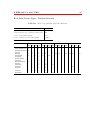
B.1.3 MAC Messages . . . . . . . . . . . . . .
B.1.4 MAC Device Types - Detailed Overview
78
78
78
79
80
81
.
.
.
.
.
.
.
.
.
.
.
.
.
.
.
.
.
.
.
.
.
.
.
.
.
.
.
.
.
.
.
.
.
.
.
.
.
.
.
.
.
.
.
.
.
.
.
.
.
.
.
.
.
.
.
.
.
.
.
.
.
.
.
.
.
.
.
.
.
.
.
.
.
.
.
.
.
.
.
.
.
.
.
.
.
.
.
.
.
.
.
.
.
.
.
.
.
.
.
.
.
.
.
.
.
.
.
.
.
.
.
.
.
.
.
.
.
.
.
.
.
.
.
.
.
.
.
.
.
.
.
.
.
.
.
.
.
.
.
.
.
.
.
.
.
.
.
.
.
.
.
.
.
.
.
.
.
.
.
.
.
.
.
.
.
.
.
.
.
.
.
.
.
.
.
.
.
.
.
.
.
.
.
.
.
.
.
.
.
.
.
.
.
.
.
.
.
.
.
.
.
.
.
.
.
.
.
.
.
.
.
.
.
.
.
.
.
.
.
.
.
.
.
.
.
.
.
C Network Activity
76
References
78
vii
List of Figures
1.1
McGill ZigBee USB Board . . . . . . . . . . . . . . . . . . . . . . . . . . .
2.1
2.2
2.3
2.4
IEEE standards, adopted from [1] . . . . . .
IEEE 802.15.4 (ZigBee) Network Topologies
General ZigBee network stack Overview . .
Telos . . . . . . . . . . . . . . . . . . . . . .
.
.
.
.
.
.
.
.
.
.
.
.
.
.
.
.
.
.
.
.
.
.
.
.
.
.
.
.
.
.
.
.
.
.
.
.
12
14
15
20
3.1
3.2
3.3
3.4
3.5
3.6
3.7
McGumps hardware platform . . . . . . . . . . . . . . . . .
McGill ZigBee board (McZig) - McGumps peripheral board
Wireless node generic architecture model . . . . . . . . . .
McZub Logical Overview . . . . . . . . . . . . . . . . . . .
McZub Software Layers Overview . . . . . . . . . . . . . . .
USB to UART bridges . . . . . . . . . . . . . . . . . . . . .
LPC210x decoupling capacitors . . . . . . . . . . . . . . . .
.
.
.
.
.
.
.
.
.
.
.
.
.
.
.
.
.
.
.
.
.
.
.
.
.
.
.
.
.
.
.
.
.
.
.
.
.
.
.
.
.
.
.
.
.
.
.
.
.
.
.
.
.
.
.
.
23
24
25
28
28
34
38
4.1
4.2
4.3
4.4
4.5
4.6
4.7
4.8
4.9
Network topology - global prospective . . . . . . . . . . . . . .
IEEE 802.15.4 Superframe structure timing . . . . . . . . . .
Embedded software model of extendable MAC / PHY layers .
ZigBee upper layers overview . . . . . . . . . . . . . . . . . .
Foreground / Background system implementation . . . . . . .
Multitasking versus single tasks . . . . . . . . . . . . . . . . .
IEEE 802.15.4 MAC / PHY network packet breakdown layers
IEEE 802.15.4 MAC / PHY Internals . . . . . . . . . . . . . .
CAP and GTS message buffering data structure . . . . . . . .
.
.
.
.
.
.
.
.
.
.
.
.
.
.
.
.
.
.
.
.
.
.
.
.
.
.
.
.
.
.
.
.
.
.
.
.
.
.
.
.
.
.
.
.
.
.
.
.
.
.
.
.
.
.
.
.
.
.
.
.
.
.
.
41
43
44
45
47
48
49
51
54
5.1
Network activity during association . . . . . . . . . . . . . . . . . . . . . .
60
.
.
.
.
.
.
.
.
.
.
.
.
.
.
.
.
.
.
.
.
.
.
.
.
.
.
.
.
.
.
.
.
5
List of Figures
5.2
5.3
5.4
viii
62
63
5.5
5.6
5.7
5.8
5.9
Network activity during GTS allocation . . . . . . . . . . . . . . . . . . .
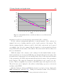
Power utilization in different scenarios . . . . . . . . . . . . . . . . . . . .
Link Quality Indicator at different distances across different transmit power
levels . . . . . . . . . . . . . . . . . . . . . . . . . . . . . . . . . . . . . .
Reception rate vs. distance vs. different output power levels . . . . . . . .
Wireless Conference Manager System high level overview . . . . . . . . . .
WCM (Handheld unit) - Photo . . . . . . . . . . . . . . . . . . . . . . . .
Application-level architecture . . . . . . . . . . . . . . . . . . . . . . . . .
Microprocessor lab kit . . . . . . . . . . . . . . . . . . . . . . . . . . . . .
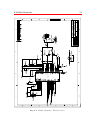
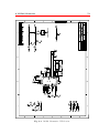
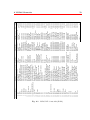
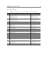
A.1
A.2
A.3
A.4
A.5
A.6
McZub
McZub
McZub
McZub
McZub
McZub
.
.
.
.
.
.
72
73
74
75
76
77
C.1 Network activity during association . . . . . . . . . . . . . . . . . . . . . .
77
Schematics - Main . . . . . .
Schematics - Wireless Section
Schematics - USB Section . .
Schematics - Power Section .
Bill of materials (BOM) . . .
PCB Layout . . . . . . . . .
. .
.
. .
. .
. .
. .
.
.
.
.
.
.
.
.
.
.
.
.
.
.
.
.
.
.
.
.
.
.
.
.
.
.
.
.
.
.
.
.
.
.
.
.
.
.
.
.
.
.
.
.
.
.
.
.
.
.
.
.
.
.
.
.
.
.
.
.
.
.
.
.
.
.
.
.
.
.
.
.
.
.
.
.
.
.
.
.
.
.
.
.
.
.
.
.
.
.
.
.
.
.
.
.
.
.
.
.
.
.
.
.
.
.
.
.
65
66
66
67
67
68
ix
List of Tables
2.1
2.2
2.3
High-level characteristics summary, adopted from [2] . . . . . . . . . . . .
802.15.4 in the context of other related IEEE standards . . . . . . . . . . .
Detailed overview of LR-WPAN vs. WLANs . . . . . . . . . . . . . . . . .
11
13
13
3.1
3.2
3.3
McZub Min/Max I/O pin count . . . . . . . . . . . . . . . . . . . . . . . .
RAM/ROM initial estimates [3] . . . . . . . . . . . . . . . . . . . . . . . .
Relevant microcontroller comparison chart (Nov. 2004) . . . . . . . . . . .
29
29
30
4.1
4.2
Firmware code size summary . . . . . . . . . . . . . . . . . . . . . . . . . .
Supported services by previous implementation . . . . . . . . . . . . . . .
57
57
5.1
Operating modes and their associated power consumption . . . . . . . . .
64
B.1 Mapping of message or function identifiers to 802.15.4 primitives . . . . . .
B.2 Device types and the respective functions . . . . . . . . . . . . . . . . . . .
80
81
1
Chapter 1
Introduction
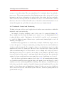
Wireless communication dates back into the history of mankind. Even in ancient times,
people used communication systems, which can be categorized as wireless. Examples are
flags, flashing mirrors, smoke signals, fires, etc. It is reported that the ancient Greeks
utilized a communication system comprising a collection of observation stations on hilltops,
with each station visible from its neighboring one. It is very similar to what J.R.R. Tolkien
described in his third book of the Lord of The Rings saga. Upon receiving a message from
a neighboring station, the station personnel repeated the message in order to relay it to
the next neighboring station. Using this system messages were exchanged between pairs of
stations far apart from one another. However, it is more logical to assume that the origin
of wireless networks, as we understand them today, starts with the first radio transmission.
The first demonstration of a radio transmission took place in 1893, when Nikola Tesla, an
American-Yugoslavian inventor, carried his first experiments with high frequency electric
currents. It is the same year that Tesla described his radio apparatus in detail in his
articles and lectures. In 1897 he registered the first patent on radio communication [4, 5].
Nevertheless, it was Guglielmo Marconi, an Italian inventor, that thrived on Tesla’s 17
patents when he received the letter ”S”, telegraphed from England to Newfoundland in
1901. Over the years that followed Marconi’s activities, radio-based transmission continued
to evolve. The origins of radio-based telephony date back to 1915, when the first radiobased conversation was established between ships [6].
Currently the field of wireless communications is one of the fastest growing segments
of the telecommunications industry. Wireless communication systems, such as cellular,
2005/08/24
1 Introduction
2
cordless and satellite phones have found widespread use and have become an essential tool
in many peoples every-day life, both professional and personal. Wireless data networks, in
particular, have led this trend due to the increasing exchange of data in Internet services
such as the World Wide Web, e-mail, and data file transfers. The capabilities needed to
deliver such services are characterized by an increasing need for data throughput in the
network. Wireless Local Area Networks (WLANs) provide an example of this phenomenon.
As the need for mobility and the cost of laying new wires increases, the motivation for a
personal connection independent of location to that network also keeps increasing.
To support this mobile lifestyle, especially as work becomes more intensely informationbased, companies are producing various portable and embedded information devices including cellular telephones, smart phones, PDAs and active badges. At the same time,
recent advances in sensor integration and electronic miniaturization are making it possible to produce sensing devices equipped with significant processing memory and wireless
communication capabilities to create smart environments where scattered sensors could
coordinate to establish a communication network. These wearable computing devices and
ad-hoc smart environments impose unique requirements on the communication protocol
design such as low power consumption, frequent make and break connections, resource
discovery and utilization and have created the need for Wireless Personal Area Networks
(WPANs).
1.1 Wireless Personal Area Networks (WPANs) History
WPANs initially belonged to the category of relatively short-distance wireless networks
specifically designed for interconnecting devices centered around an individual person’s
workspace. The objective of WPANs was to facilitate seamless operation among home
or business devices and systems. A key concept in WPAN technology has been known
as plugging in. In the ideal scenario, when any two WPAN-equipped devices come into
close proximity (physical range of one another) or within a few kilometers of a central
server, they can communicate as if connected by a cable. Another important feature is the
ability of each device to lock out other devices selectively, preventing needless interference
or unauthorized access to information.
Wireless Local Area Networks (WLANs), on the other hand, typically cover a moderately sized geographic area such as a single building, or campus. WLANs operate in the 100
1 Introduction
3
meter range and are intended to augment rather than replace traditional wired LANs [7, 8].
They are often used to provide the final few feet of connectivity between the main network
and the user. Users can plug into the network without having to look for a place to link
their computer, or having to install expensive components and wiring.
WPANs are the next step down from LANs and target applications that demand lowpower and relatively short range communications. Early research for PANs was carried
out in 1996. However, the first attempt to define a standard for PANs dates back to
an Ericsson project in 1994, which aimed to find a solution for wireless communication
between mobile phones and related accessories (e.g. hands-free kits). This project was
named Bluetooth [9, 10] (after the name of the king that united the Viking tribes). It is
now an open industry standard that is adopted by more than 100 companies and many
Bluetooth products exist and are appearing in today’s market place. Bluetooth operates
in the 2.4 MHz ISM band; it supports 64 kbps voice channels and asynchronous data
channels with rates ranging up to 721 kbps. Supported ranges of operation are 10 m (at 1
mW transmission power) and 100 meters (at 1 mW transmission power).
Another PAN project was HomeRF [11]; the latest version before discontinuing the
project was released in 2001. This version offered 32 kbps voice connections and data rates
up to 10 Mbps. HomeRF also operated in the 2.4 MHz band and supported ranges around
50 m. In 1999, IEEE joined the area of PAN standardization with the formation of the
802.15 Working Group [12, 13]. Due to the fact that Bluetooth and HomeRF preceded the
initiative of IEEE, a target of the 802.15 Working Group was to achieve interoperability
with these projects. Bluetooth was eventually standardized as IEEE 802.15.1 [14], has a
raw data rate of 1 Mb/s; [15, 10], and IEEE 802.15.3, released in June 2003, has a maximum
raw data rate of 55 Mb/s [16]. Both the 802.11 and 802.15 organizations have begun the
definition of protocols with data throughputs greater than 100 Mb/s.
However, there are other potential wireless network applications. These applications,
which have low-data rate requirements and are often measured in a few bits per day, include
industrial control and monitoring; home automation and consumer electronics; security and
military sensing; asset tracking and supply chain management; intelligent agriculture; and
health monitoring.[17] Because most of these low-data-rate applications involve sensing of
one form or another, networks supporting them have been called wireless sensor networks
(WSNs), or Low-Rate WPANs (LR-WPANs). Among recent IEEE standards, released
in 2003, it is 802.15.4 [18] that defines an ultra-lightweight communication protocol that
1 Introduction
4
transmits only the few required bytes per second per node, enough to satisfy application
requirements but no more than that. The low data rate enables the LR-WPAN to consume
very little power by realizing low duty cycles up to 15 ms in 252 s (active/sleep = 1/16400).
ZigBee technology is a low data rate, low power consumption, low cost, wireless networking protocol targeted towards automation and remote control applications. IEEE 802.15.4
committee started working on a low data rate standard a short while later. Then, in 2003
the ZigBee Alliance [19, 20] and the IEEE decided to join forces and ZigBee, HomeRF
spinoff, emerged as the commercial name for this technology. ZigBee to IEEE 802.15.4 is
the same what Bluetooth is to IEEE 802.15.1. ZigBee is expected to provide low cost and
low power connectivity for equipment that needs battery life as long as several months to
several years but does not require data transfer rates as high as those enabled by Bluetooth. In addition, the standard defines several types of network topologies in order to
accommodate several hundreds of nodes.
Currently, two active task groups i.e. 802.15.4a and 802.15.4b are working on expanding
as well as enhancing the standard. The 802.15.4b is in charge of specific enhancements and
clarifications to the IEEE 802.15.4-2003 standard, whereas 802.15.4a concentrates on the
physical layer aiming to increase throughput, reduce power consumption and scale down
the overall cost. Since 802.15.4 task group sized to exist in March of 2004, transferring
all their activities to 802.15.4b, the two task groups will be used interchangeably in this
document.
1.2 Contribution of the Thesis
Among the presented WPAN standards and industry groups in the previous section, special
interest is devoted to the emerging IEEE 802.15.4 wireless standard. In fact, this project
concentrates on both hardware and software design and implementation challenges revolving around the above mentioned standard - low-power and low-cost. For the simplicity in
this thesis several terms denoting WPANs will be used interchangeably: PAN, Personal
Area Networks, and IEEE 802.15 workgroup.
With recent advances in CMOS integrated circuits, the integration of an Radio Frequency (RF) front end onto the same die as the digital demodulation and media access
control components became a common goal for many manufacturers. The high level of
integration allows designers to add wireless networking capabilities to many embedded
1 Introduction
5
systems for a few dollars in additional costs.
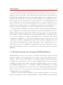
The work presented in this thesis is based on the design and integration challenges of
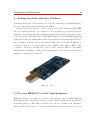
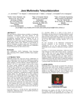
latest Application Specific Integrated Circuits (ASICs) into a full wireless embedded system. The system’s code name is McZub, and it stands for McGill ZigBee USB Board,
Figure 1.1. It is a dedicated embedded system that includes software and hardware components, designed to be a high performance, low-power IEEE 802.15.4 compliant network
coordinator providing ubiquitous USB connectivity. It is meant to be a testbed prototype
device for research in the domain of low-rate personal area networks (LR-WPANs). At the
time when it was manufactured it was was the first of its kind in the world 1 .
Fig. 1.1
McGill ZigBee USB Board
1.2.1 Design Goals and Research Problems
The central component of this thesis is the McZub board. Based on the specific setups
available and the global research interests of the MACS Lab, a list of design goals was
established on both hardware and firmware fronts. These goals will be referred to as
1
To the author’s knowledge
1 Introduction
6
(DG) in the rest of this thesis. Note that firmware and embedded software will be used
interchangeably throughout the thesis.
Hardware, Chapter 3:
(DG1) Partitioning: The partitioning design decisions are of paramount importance,
especially at the start of a wireless node design. State necessary decisions to balance
current and future technological capabilities in order to meet all the requirements
and at the same time achieve robust and easily upgradeable system.
(DG2) Low-Power: Required considerations as to the selection of a power sources, power
regulators and other board components.
(DG3) Low-Cost: How to maintaining low-cost of the overall design - development and
manufacturing costs, as well as operating costs.
(DG4) Compatibility: Maintain network/protocol compatibility with respect to existing
hardware within the MACS research group.
(DG5) Reliability/Robustness: Board layout, testing and assembly techniques. Subtleties in achieving robust (RF) section - antenna layout, matching network.
Embedded Software / Firmware, Chapter 4:
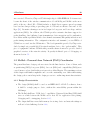
(DG6) IEEE 802.15.4 MAC/PHY Implementation: Modular and expandable protocol stack implementation, according to IEEE specifications.
(DG7) Protocol Portability: Maintaining concise hardware abstraction layers in order
to facilitate source code maintenance across different platforms.
(DG8) Real-Time Operating System (RTOS) selection: Exploring benefits and
detriments among RTOS distributions, their complexity, memory requirements and
ease of porting to different platforms.
1.2.2 Thesis Overview
In depth comparisons and features of both IEEE 802.15.4 and ZigBee are presented in
Chapter 2. In addition, it discusses numerous applications of the technology that further
strengthen and emphasize the motivation for the presented work. Chapter 3 presents
the McZub hardware design decisions, implementation and testing challenges. Further,
Chapter 4 elaborates on 802.15.4 MAC/PHY protocol implementation. Moreover, it shows
1 Introduction
7
firmware design decisions such as low-memory footprint Application Programming Interface
(API) realization, RTOS integration as well as inter PC communication protocol. The key
metric used to evaluate the performance of the system involves integrating McZub with
existing hardware platform - McGumps [21] and McZig [22]. These and other results are
presented in Chapter 5.
8
Chapter 2
Background and Motivation
I never think of the future - it comes soon enough.
−Albert Einstein
Before describing McZub hardware and firmware design and implementation decisions
and subtleties, an in-depth presentation of IEEE 802.15.4 standard and ZigBee is in order.
It is crucial to understand the motivation as well as the context in which this wireless
technology is to be used. In Section 2.1, an overview of the LR-WPANs is given. Its
goals, characteristics, relation to other widely adopted IEEE and industry standards are
also described in this section. The impact on the society as well as potential application
variety of LR-WPANs is given in Section 2.2. A short overview of the existing hardware
platform is presented in Section 2.3.
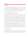
2.1 IEEE 802.15.4 Standard for Low-Rate WPANs (LR-WPANs)
The IEEE 802.15.4 LR-WPAN task group has been put in charge to develop a standard for
Low-Rate Wireless Personal Area Networks (LR-WPANs) [23]. It is a standard that was
developed to convey information over short distances in a power efficient manner. This is
a very new technology since the IEEE Standards board approved the IEEE 802.15.4 draft
18 on May 12, 2003. It is worth mentioning that ZigBee/802.15.4 related research within
the McGill Microelectronic and Computer Systems (MACS) research group started shortly
after, in September of 2003.
2005/08/24
2 Background and Motivation
9
Until recently, the primary activity in networking technology has been focused on productivity and entertainment applications running on PCs. For wireless technologies, this
translates to high bandwidth. The attention of the wireless communications industry and
researchers has now spread beyond the office and home to include new environments such
as factories, hospitals, and agriculture. Furthermore, applications in these new areas are
becoming increasingly dependent upon embedded systems. Traditional wireless technologies are often not suitable in this context due to reasons of practicality, hence the need for
a new standard that focuses on these new special requirements.
Applications such as home automation, security, and gaming have these relaxed throughput requirements. These applications cannot handle the complexity of heavy protocol stacks
that impact power consumption and utilize too many computational resources. Naturally,
this has a direct implication on cost. Consider a security device used as an identification tag
for a piece of equipment or visitor to a plant. This security sensor may need to report the
location of it’s host only after the movement has been detected. At other times, the device
will be hibernating, hence saving power. Unsurprisingly, such security system would further
require many of these devices and therefore they must have a very low selling point. This
application is an excellent candidate for a low-throughput low-cost wireless communications
link. In addition, it must be extremely low power, since frequent battery replacements are
impractical and costly. It is evident that 802.11b or 802.11g is an overkill technology for
this application that can only satisfy the connectivity requirement, jeopardizing low-power
and low-cost. Bluetooth was originally engineered as a cable replacement and cannot be
used in applications where connectivity of more than seven nodes is needed [9]. Please,
refer to section 2.1.2 and table 2.3 for detailed comparison among the above mentioned
IEEE standards.
2.1.1 Goals and Characteristics
Generally, the applications that IEEE 802.15.4 addresses are characterized by their requirements for low-power consumption and low-cost deployment [24].
Ultra-Low Power Consumption: On any wireless embedded system, the radio is often
one of the largest consumers of energy–even more than the CPU. The embedded
systems that are expected to utilize IEEE 802.15.4 for communication have extremely
tight energy constraints, operating off of a small battery for a period of months and
2 Background and Motivation
10
even years.
Very Low Cost: The final cost of the component implementing the IEEE 802.15.4 standard must be small compared to the cost of the rest of the component. The reason
for this is that the deployed applications are envisioned to be composed of possibly
numerous, inexpensive, and even disposable devices.
In order to achieve the low power and low cost goals established by IEEE 802.15.4 the
following approaches are taken:
• Reduce the amount of transmitted data
• Reduce the transceiver duty cycle and frequency of data transmissions
• Reduce the frame overhead
• Reduce complexity
• Reduce range
• Implement strict power management mechanisms (power-down and sleep modes)
All of these design decisions contribute to lower power and lower cost requirements. They
are directly reflected in the IEEE 802.15.4 Media Access Control (MAC) and Physical
layers (PHY).
MAC Decision Highlights:
Network Topology: The common configuration of an LR-WPAN will be a star or starcluster topology. The master node at the center of the star (or cluster-head, in the
case of star-clusters) simplifies control and synchronization of the nodes participating
in the network.
Homogeneous vs. Heterogeneous Devices: At the MAC layer, components may be
identified as a fully functional (FFD) or reduced functional device(RFD). Therefore,
if the application accommodates them, reduced functional devices may be attached
to the network as leaf nodes, which simplifies their implementation and precludes
these devices from forwarding messages, allowing them to save on power.
Message Structure: The structure used is very simple compared to other WLAN/WPAN
standards, allowing for very short messages to conserve power.
PHY Decision Highlights:
2 Background and Motivation
11
2.4 GHz band: This frequency is unlicensed and widely available for use. Existing lowcost designs for this band makes device manufacturing more affordable.
868/915 MHz band: Lower power consumption than 2.4 GHz and are freely available
for use in Europe and the United States respectively.
Data Rate: Power can be saved by maximizing the data rate for any given amount of data
that needs to be transmitted. Thus IEEE 802.15.4 allows up to 250kbs. However, the
real power savings comes from transceiver duty cycling, which is expected to be about
0.33% for many applications. The high data rate allows the standard to accommodate
applications that need higher throughput, but that can tolerate increased latency in
order to save power.
Link Quality: Provides energy and link quality detection, clear channel assessment for
improved coexistence with other wireless networks.
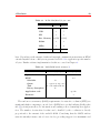
The main 802.15.4 characteristics are summarized in Table 2.1.
Table 2.1
High-level characteristics summary, adopted from [2]
Property
Range
Raw data rate
Range
Channels
Frequency band
Addressing
Channel access
Temperature
868 MHz: 20 kb/s; 915 MHz: 40 kb/s; 2.4 GHz: 250 kb/s
50 - 300 meters
868MHz: 1 channel; 915 MHz: 10 channels; 2.4 Ghz: 16 channels
Two PHYs: 868 MHz/915 MHz and 2.4 GHz
Short 16-bit or 64-bit IEEE
CSMA-CA and slotted CSMA-CA
Industrial temperature range -40 to +85 C
2.1.2 Relation to Other IEEE 802 standards
Institute of electrical and electronics engineers (IEEE) has initiated numerous networking
work groups over the years [13], some of which are still active, others that have matured or
have been discontinued. The working groups are the driving force behind open standards
that define both wireless and wired networking protocols. In addition, several groups have
been established as discussion or study groups. Among the discussed topics is coexistence
between standards, which are covered by 802.15.2 and 802.19.
2 Background and Motivation
12
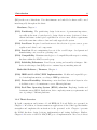
The IEEE work groups cover an extended amount of networking concepts such as:
Personal Area Network (PANs), Local Area Networks (LANs), Metropolitan Area Networks
(MANs) and the most recently established - Regional Area Networks (RANs). Figure 2.1
depicts all of the above mentioned concepts, as well as provides concise information on how
they are interrelated based on the operating frequencies and range.
Fig. 2.1
IEEE standards, adopted from [1]
The IEEE 802.15 working group defines three classes of WPANs characterized by data
rate, power usage, and quality of service:
802.15.1: Medium-rate: Voice applications, PDAs, etc. Known as Bluetooth.
802.15.3: High-data-rate, High quality of service. Good for multimedia applications.
802.15.4: Lower cost/power/data-rate/QoS than 802.15.1. Known as ZigBee.
The IEEE 802.15.2 task group tackles coexistence issues between WLANs (802.11) and
WPANs (802.15). Table 2.2, shows the IEEE 802 hierarchy as well as the major industry
players involved with its respective technology.
Among the existing network technologies WLANs are commonly being compared to
WPANs mostly because they are currently the major player in wireless communications.
Table 2.3 further breaks down the differences between WPANs and WLANs.
2 Background and Motivation
Table 2.2
13
802.15.4 in the context of other related IEEE standards
Standards
Committee
IEEE 802: LAN/MAN Standards Committee
Working
Group
IEEE 802.11: WLAN
Task
Group
802.11a/b/g
802.15.1:
WPAN/Bluetooth
802.15.3a:
WPAN
High Rate/UWB
802.15.4: WPAN Low
Rate/Zigbee
Industry
Alliance
Wi-Fi: Cisco, 3Com,
Agere, Intersil, Compaq, Dell, Sony, Nokia,
Symbol, etc.
Bluetooth SIG: Ericsson, 3Com, IBM, Intel, Motorola, Nokia,
Agere, Toshiba, etc.
Wi-Media:
Appairent, HP, Motorola,
Philips,
Samsung,
Sharp,
XtremeSpectrum, etc.
Zigbee
Alliance:
Chipcon, Ember, Honeywell,
Mitsubishi,
Motorola,
Philips,
Samsung, etc.
Table 2.3
IEEE 802.15: WPAN
Detailed overview of LR-WPAN vs. WLANs
802.11
802.15.1
802.15.4
Range
∼100 m
∼10 m
∼(70 - 300) m
Power profile
Hours
Days
Years
Nodes/Master
32
7
65536
Data rate
(11 - 54)Mbps
1Mbps
250Kbps
Security
SSID
64bit, 128bit
128bit AES
Modulation
Various
FSK
BPSK and O-QPSK
Size/Complexity
Larger
Smaller
Smallest
Cost ($US)
>6
1
0.2
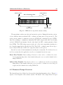
The IEEE 802.15.4 protocol was developed for a very different reason than 802.15.1
(BlueTooth). It features very low duty cycle and very long primary battery life by remaining
quiescent for long periods of time without communicating to the network. Furthermore, it
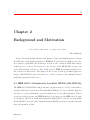
benefits from more complex network topologies, such as: static and dynamic mesh, cluster
tree and star network structures with potentially very large number (∼ 65534) of client
units, Figure 2.2.
Bluetooth was conceived as a wire replacement for consumer devices that need moderate
data rates with a very high quality of service (QoS) and guaranteed low latency. The
network topologies are less complex, comparing to 802.15.4 with only a quasi-static star
network structure with up to 7 clients (and ability to participate in more than one network
simultaneously) [15]. It is generally used in applications where the batteries are frequently
being recharged (headsets, cellphones) or constantly powered via an independent source
2 Background and Motivation
14
Mesh
Star
PAN coordinator
Full Function Device
Cluster Tree
Reduced Function Device
Fig. 2.2
IEEE 802.15.4 (ZigBee) Network Topologies
(printers, car kits).
2.1.3 ZigBee
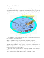
IEEE and ZigBee Alliance [20] have been working closely to specify the entire protocol stack
to be used in low-power and low-rate applications. As mentioned in Section 2.1.1, IEEE
802.15.4 focuses on the specification of the lower two layers of the protocol (physical and
data link layer). On the other hand, ZigBee Alliance aims to provide the upper layers of
the protocol stack (from network to the application layer) for interoperable data networking, security services and a range of wireless home and building control solutions, provide
interoperability compliance testing, marketing of the standard, advanced engineering for
the evolution of the standard [19], Figure 2.3. As any standard, ZigBee is no different it will guarantee its consumers that products purchased from different manufacturers will
work together. A unique feature of ZigBee network layer is communication redundancy
eliminating single point of failure in mesh networks [25].
2.2 Applications of LR-WPANs / ZigBee
ZigBee represents an industry initiative to enable the construction of business and residential network applications using low-cost, low-power sensors that run on batteries with very
2 Background and Motivation
APPLICATION/PROFILES
15
ZigBee or OEM
APPLICATION FRAMEWORK
NETWORK/SECURTIY
LAYERS
ZigBee
Alliance
Platform
MAC LAYER
PHY LAYER
Fig. 2.3
IEEE
General ZigBee network stack Overview
long lives. The standard is backed up by an industry consortium with more than 150 active
members, called The ZigBee Alliance [20].
The likely applications may range from lighting control; heating, ventilating and air
conditioning (HVAC) environmental management; industrial sensors and various consumer
electronics. The following list captures the basic five domains in which wireless sensor
networks (WSN) are used:
Control: Integrate and centralize management of lighting, heating, cooling and security;
Improve complicated process control mechanisms.
Conservation: Capture highly detailed electric, water and gas utility usage data. Automate control of multiple systems to reduce power consumption.
Convenience: Install, upgrade and network home control system without wires. Configure and run multiple systems from a single remote control.
Safety: Deploy monitoring networks to enhance employee and public safety. Receive automatic notification upon detection of unusual events
Efficiency: Automate data acquisition from remote sensors to reduce user intervention
The following subsections explore how LR-WPANs, together with ZigBee, efficiently meet
the above mentioned goals in more detail.
2 Background and Motivation
16
2.2.1 Home Automation and Consumer Electronics
The home is a very large application space for wireless sensor networks [24]. A home
HVAC system equipped with wireless thermostats can effectively control the temperature
throughout the house. Depending on the time of the day and the orientation of the house
the temperature in the rooms can easily be adjusted to suite a sunny or a shady side.
On the other hand, regular, wired thermostats, fall short as the overall complexity of the
environment is taken into the account. In addition, home sensor networks could automatically determine when there’s no one in the house and then turn off lights, heat and air
conditioning to conserve energy.
A potential ”killer application” is the universal remote control, a device that can control
not only the home theater, stereo, and other home electronic equipment, but the lights,
curtains, and locks that are also equipped with a WSN connection. An interesting scenario
could be realized by combining multiple services. For example, having the curtains close
automatically when the television is turned on.
Another application in the home is sensor-based information appliances that transparently interact and work symbiotically together as well as with the home occupant [26].
These networks are an extension of the information appliances proposed by Norman [27].
Toys represent another large market for wireless sensor networks [28]. The list of toys
that can be enhanced or enabled by wireless sensor networks can range from conventional
radio-controlled cars and boats to computer games employing wireless joysticks and controllers.
2.2.2 Social Event Tracking
While many sensing applications do not require the direct use of wireless units by humans,
an interesting subset of applications would require an effective human interface, including
sufficiently high-resolution touch-screen displays. Combining location-aware capabilities of
WSNs, a diverse collection of consumer-related activities exist including tourism [29], shopping [30] and event tracking. Events and venues can be very different - social gatherings,
sporting events, etc. One such system, has been developed in-house - Wireless Conference
Manager (WCM), Section 5.2.
2 Background and Motivation
17
2.2.3 Security and Military Sensing
Security systems that employ proprietary communication protocol have existed for several
years [31]. They can support multiple sensors relevant to industrial security, including
magnetic door opening, smoke and broken glass sensors, passive infrared and others.
As with many technologies, some of the earliest proposed uses of wireless sensor networks were for military applications [32]. One of the great benefits of using wireless sensor
networks is that they can be used to replace guards around defensive perimeters, keeping
soldiers out of harm’s way. In addition to such defensive applications, deployed wireless
sensor networks can be used to locate and identify targets for potential attack, and to
support the attack by locating friendly troops and unmanned vehicles [33].
Wireless sensor networks can also be effective in the monitoring and control of the
population with the use of optical, audio, chemical, biological, and radiological sensors to
track individuals and groups, as mentioned in Section 2.1. The control of WSNs and the
data they produce in a free society is a topic of many discussions [34, 35].
2.2.4 Asset Tracking and Supply Chain Management
A very large unit volume application of wireless sensor networks is related to asset tracking
and supply chain management. Radio Frequency Identification (RFID), which is a subset of
LR-WPANs [36], is a main technology behind asset tracking that can take many forms. One
example is the tracking of shipping containers and their storage within large warehouses
or air terminals. Such warehouse facilities may have tens of thousands of containers, some
of which are empty and in storage, while others are bound for many different destinations.
An important factor in the shipper’s productivity and consequentially profitability is how
efficiently the orders can be organized so that they can be handled the fewest number of
times and with the fewest errors.
Efficient inventory tracking, both quantity and its location is of paramount importance
for any manufacturer or supplier. Knowing where a product is can mean the difference
between making or not making a sale, but knowing the status of the entire supply chain
from raw materials through components to final product can help a business operate more
efficiently.
Accurate inventory information can also be used as a competitive advantage. By being
able to tell a customer exactly where his product is in the supply chain, the customer’s
2 Background and Motivation
18
confidence of on-time delivery and opinion of the seller’s competence rises. This has already
been used extensively in the package shipping industry a shipper that cannot tell a customer
where his or her package is at any given time is rarely given a second chance [36].
2.2.5 Intelligent Agriculture and Environmental Sensing
The wireless sensor networks could be widely used in various applications where accurate
information about the current environment could result in natural resource savings. For
example, large farms could deploy numerous sensors in order to monitor precipitation levels.
If the irrigation may be omitted in certain parts of the farm, due to sporadic rain activity,
the water savings could be immense. The amount of data sent over the network is minimal,
and hence perfect for LR-WPANs.
Other than soil moisture measurements, bio-chemical plants can benefit from lowpower sensing of environmental contaminants such as mercury [37]. Integrated microcantilever sensors sensitive to particular contaminants can achieve parts-per-trillion sensitivities. These microelectromechanical (MEMS) sensors may be integrated with a wireless
transceiver in a standard complementary metal oxide semiconductor (CMOS) process, providing a very low-cost solution to the monitoring of chemical and biological agents.
2.2.6 Health Monitoring
A market for wireless sensor networks that is expected to grow quickly is the field of health
monitoring [38].
Two general classes of health monitoring applications are available for wireless sensor
networks. One class is athletic performance monitoring, for example, tracking one’s pulse
and respiration rate via wearable sensors and sending the information to a personal computer for later analysis [38]. The other class is at-home health monitoring, for example,
personal weight management [39]. Other examples are daily blood sugar monitoring and
recording by a diabetic, and remote monitoring of patients with chronic disorders [35].
An interesting and developing field in the health monitoring market is that of implanted
medical devices. These types of systems can be used for a number of purposes, for example,
monitoring pacemakers and specialized drug delivery systems.
Wireless disaster relief systems, especially the avalanche rescue beacons, have been on
the market for some time now. These devices continuously transmit signals that rescuers
2 Background and Motivation
19
can use to locate the victim. They are naturally used by ”avalanche skiers” in avalancheprone areas. The present systems have their limitations since they only provide location
information, and give no information about the health of the victim. In a large avalanche,
where several beacons are present, the rescuers have no way to decide who should be assisted
first due to the lack of additional health sensors. Given the additional information about
victim’s life signals, the probability of saving a life increases dramatically [40].
2.2.7 Industrial Control and Monitoring
The final, and most widely accepted applications of wireless sensor networks are within the
industrial control and monitoring.
An example of wireless industrial control is the control of commercial lighting [41].
From a simple hand held unit the lights can be turned on or off eliminating the need
to physically flip a switch. Furthermore, the hand held controller can be programmed
to control the lighting in many different ways - synchronously turning lights on and off,
dimming of the lights, etc.
Industrial safety applications are another major example. WSNs may employ sensors
to detect the presence of dangerous materials, providing early detection and identification
of leaks or spills of chemicals. For example, workers on an oil platform carry devices that
signal increased levels of certain gases. However, due to sudden release of these gases the
workers sometimes simply do not have time to act accordingly and could get poisoned.
Currently these sensor boxes, carried by the workers, are not linked to the main control
tower and therefore help cannot be sent immediately after the incident. By replacing the
existing local sensors with wireless sensors many lives across oil platforms can be saved.
As in the home applications mentioned in Section 2.2.1, the manufacturing industry
can benefit from wireless sensor networks that would monitor heat and therefore control
ventilation, and air conditioning (HVAC) of buildings. The efficiency of any HVAC system
is directly proportional to number of installed thermostats and humidistats. However, the
number of these thermostats and humidistats is limited by the costs associated with their
wired connection to the rest of the HVAC system. Therefore, WSNs are gaining tremendous
ground in this area [18].
2 Background and Motivation
20
2.3 Existing Low-Power Hardware Platforms
Considering the novelty of the wireless protocol and the availability of compliant hardware,
the choices among the existing platforms were limited.
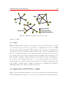
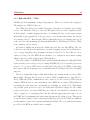
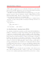
Shortly after the project was conceived, Moteiv [42] released their first WSN IEEE
802.15.4 compliant platform - Telos, Figure 2.4. It is an ultra low power wireless module
designed for use in sensor networks,
monitoring applications and rapid prototyping. Moteiv,
Rev A (Low Power Wireless Sensor Module)
being closely related with University of California at Barkeley, provides full TinyOS support
for their Telos platform, which greatly reduces development and deployment time. However,
since it features an ultra-low power and memory limited microcontroller, TI MSP430, it
is an ideal solution for a reduced function device (RFD), rather than an FFD - PAN
tra low power IEEE
802.15.4
compliant
wireless
module
coordinator.
Needless
to say that
Telos, sensor
can be closely
compared with our own existing
vision A : Humidity, Light, and Temperature sensors with USB
WSN platform - McGumps + McZig, described in Chapter 3, since the microcontroller and
transceiver components are identical.
Telos
elos
oduct Description
os is an ultra low power wireless
dule for use in sensor networks,
nitoring applications, and rapid
plication prototyping. Telos
erages industry standards like USB
d IEEE 802.15.4 to interoperate
mlessly with other devices.
using industry standards,
grating humidity, temperature, and
t sensors, and providing flexible
rconnection with peripherals, Telos
ables a wide range of mesh network
plications. With TinyOS support
-of-the-box, Telos leverages emerging wireless protocols and the open source software
Fig. 2.4 Telos
vement. Telos is part of a line of modules featuring on-board sensors to increase robustness
le decreasing cost and package size.
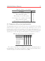
2.4 Previous IEEE 802.15.4 MAC Implementations
ey Features
•
•
•
•
•
•
•
•
•
•
During the last two years since the adoption of the standard only two MAC/PHY im-
250kbps 2.4GHz IEEE 802.15.4 Chipcon Wireless Transceiver
plementations
have been
publicly announced none of which are fully and freely available.
Interoperability with
other IEEE 802.15.4
devices
8MHz Texas Instruments
MSP430
microcontroller
(2k RAM,
ROM) the two industry rivals, announced
In the first
quarter
of 2005 Chipcon
and60k
Freescale,
Integrated onboard antenna with 50m range indoors / 125m range outdoors
semi-open 802.15.4 libraries i.e. sources for the physical layer and binaries in case of the
Integrated Humidity, Temperature, and Light sensors
Ultra low current consumption
Fast wakeup from sleep (<6µs)
Hardware link-layer encryption and authentication
Programming and data collection via USB
12-pin expansion support and optional SMA antenna connector
2 Background and Motivation
21
media access control that are being distributed with their respective development kits. The
only implementation available for comparison was a “Zigbee implementation on McGumps
evaluation board”, by Kin Lam [43].
Unfortunately, the McGumps implementation lacked numerous essential features described in the standard. Moreover, the implemented routines lacked robustness and efficiency, both on the CPU as well as power usage fronts. This is clearly present throughout
the firmware design where countless while loops are used to poll software, as well as hardware flags thus wasting CPU cycles and hence the power. Both software and hardware
flags are usually set as a result of a coordinated hardware interfacing routine. Therefore,
such blocking loops, in addition to being power inefficient, are likely to cause permanent
program stalls if hardware misbehaves that can be resolved only by system reset. Any
such blocking loop should always have a timeout associated with it in order to prevent the
unrecoverable firmware halts.
22
Chapter 3
Hardware
Little by little, one travels far.
−J. R. R. Tolkien
This chapter covers the hardware portion of this project. A generic wireless node design is
covered in Section 3.1. Several aspects were explored in order to come up with an optimal
design in order to meet our four hardware DGs, Section 1.2.1. A more in-depth look into
the McZub implementation as well as necessary hardware troubleshooting is overviewed in
Section 3.2.
3.1 Wireless Node Design
The design of wireless network node is of primary importance in the design of a wireless
sensor network. The most important factors that determine the success of a wireless sensor network are its low-cost, low-power, size and reliability. The network protocol does
play a significant role in the overall reliability and low power usage, however, this chapter
concentrates on examining hardware design decisions that were employed to achieve the
set objectives. At the start of the McZub project, the MACS research group had already
developed the low-power hardware platform to be used in teaching as well as wireless sensor
node research1 . The overall design strategies as well as compatibility issues (DG4) between
the two platforms are considered in this section.
1
The members of the MACS group that developed the platform are: Jean-Samuel Chenard, Milos
Prokic, Rong Zhang, Usman Khalid and Zeljko Zilic
2005/08/24
3 Hardware
23
3.1.1 Existing Low-Power Hardware Platform
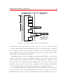
The existing hardware platform, McGill Microprocessor Systems board (McGumps) has
been designed to be expandable and to facilitate complex research and teaching goals [21,
44]. The platform benefits from the complex programable logic device (CPLD) that is used
to rapidly prototype any external hardware [45]. The ultra-low power 16-bit RISC type
microcontroller MSP430 from Texas Instruments provides sufficient computing resources
while keeping power consumption in the neighborhood of 1mW/MIPS [46] or less. Since
analog as well as digital lines from the MSP430 are routed to the expansion headers sensor
or actuator modules can be easily added. Choosing this family of microcontrollers for the
embedded nodes certainly was also heavily influenced by its low cost. Figure 3.1, depicts
main components as well as an example WSN node configuration with an LCD and touch
screen (TS). The example featuring LCD and TS - Wireless Conference Manager is further
described in Section 5.2. In addition, board features an interface to the Dallas iButton
that allows access to a vast array of compatible devices: temperature switches and sensors,
digital potentiometers, etc. So far, three different expansion boards were designed, one of
Main Board - McGumps
UART
JTAG
MCU
CPLD
Texas
Instruments
MSP430F149
ALTERA
MAX
7000
Wireless Board
McZig
Chipcon CC2420
Printed Antenna
IButton
HexLED
MMC
LCD Board
Screen 160x160
EPSON SED13700
TI TSC2046
System Diagram
Fig. 3.1
Photo
McGumps hardware platform
which is used for wireless communication - McGill ZigBee Board - McZig, Figure 3.2. The
3 Hardware
24
module is based on the Chipcon CC2420 integrated radio transceiver. The background
and rationale behind choosing this particular transceiver is covered in Section 3.1.3. In
addition, the board features an integrated printed antenna, removing fragile parts and
hence providing a low-cost module. The reader wanting to know more about the the novel
methodology for designing nodes in which a robust antenna is realized by printed circuit
traces may consult Design Methodology for Wireless Nodes with Printed Antennas [22].
Antenna
Wireless
Circuit
Top
Fig. 3.2
Bottom
McGill ZigBee board (McZig) - McGumps peripheral board
3.1.2 General Design Strategy
The common-off-the-shelf (COTS) microcontroller-based system architecture was considered as the implementation technology of choice. The generic structure of both the WSN
nodes (McGumps + McZig) and the PAN coordinator (McZub) is depicted in Figure 3.3.
This design has many benefits and it came about when the world’s first IEEE 802.15.4
compliant chip was released. By keeping the RF front-end constant throughout the design
cycle it allows for experimentation with different microcontroller architectures to accommodate multiple application platforms. Moreover, it guarantees their seamless integration
into the already existing network. Furthermore, the RF chip non-binding architecture can
provide a smooth transition to a different device if changing the operating band is required
(DG1).
As shown in Figure 3.3, a single processor architecture is used for both protocol handling and application data processing. Naturally, wireless sensor networks are assumed to
have relatively low data throughput and total amount of processing required to be fairly
3 Hardware
25
low. In addition, it reduces complexity and power consumption which is one of the main
characteristics of wireless sensor networks. An attractive approach could have been to employ a dedicated protocol handler to off-load the host processor, and use the resources of
the host processor for application data processing. This could have been a more elegant
approach, but would have inflicted unnecessary cost, which would directly be at odds with
DG3 (low-cost).
RF Front-end
Fig. 3.3
Protocol Handler /
Application
handler
DATA
Wireless node generic architecture model
The IEEE 802.15.4 standard [2] specifies two types of devices: a Full Function Device
(FFD) and a Reduced Function Device (RFD). The difference between the two types is
that the FFD or PAN coordinator, must have enough memory and computing power to
manage all the devices, RFDs, present in the network. An FFD can take the role of a
ZigBee Coordinator, Router or End Device depending on the ZigBee logical device type
configuration. An RFD can act as a ZigBee End Device and cannot serve as a ZigBee
Coordinator or ZigBee Router [47].
During the design stages of the McGumps platform several processor architectures were
explored. The Texas Instruments’ MSP430 processor is among the most energy efficient
ones to date. Nonetheless, since low-power systems are inherently RAM and MIPS-limited,
the embedded software component needed to be optimized to compensate for these shortcomings, Section 4. Among the members of the MSP430 family, MSP430F149 has been
chosen, featuring 60K FLASH and 2K RAM. Since, this device only requires a fraction of
the full 802.15.4 MAC layer (as RFD) the above specifications proved to be sufficient.
The PAN coordinator (FFD), needing to have more computational power and memory
had to belong to a different family of processors. The architecture examination as well as
other aspects of the McZub design are presented in Section 3.2.
3.1.3 Wireless Transceiver
Zigbee compliant hardware was the top choice, as offered by Freescale [48] and Chipcon [49].
The main decisive factor was the availability of engineering samples at the time the project
3 Hardware
26
was conceived. Therefore, Chipcon CC2420 single-chip 2.4 GHz IEEE 802.15.4 transceiver
became the heart of the wireless communication of both McZig and McZub as the more
stable of the two offered ICs. CC2420 includes a digital direct sequence spread spectrum
base band modem providing a spreading gain of 9 dB and an effective data rate of 250
kbps [50]. Its main advantages are in its design for low-power and low-voltage wireless
applications (DG2). In addition, the CC2420 provides extensive hardware support for
packet handling, data buffering, burst transmissions, data encryption and for authentication. Other useful capabilities include clear channel assessment, link quality indication and
packet timing information. The configuration interface and transmit / receive FIFOs of
CC2420 are accessed via the SPI interface. The development kit provided by Chipcon included a simple yet powerful 802.15.4 network analyzer device - the “packet sniffer”. This
piece of equipment combines CC2420 with powerful software frontend to provide detailed
graphical overview of the network activity. It greatly facilitated protocol debugging, as
shown in Section 5.1.
3.2 McZub - Personal Area Network (PAN) Coordinator
The general hardware design goals were stated in the Introduction. Some of them, such
as partitioning (DG1), low-power (DG2), low-cost (DG3) and compatibility (DG4) were
covered in more or less detail in the previous section of this Chapter. The remaining sections
of this chapter will further emphasize and cover the outstanding ones. Other than stating
the design goals a crucial step in the design process is to outline important characteristics.
3.2.1 Design Characteristics
• The design (McZub) shall be used as an IEEE 802.15.4 PAN Coordinator, hence
it shall be a single purpose device, without the extendability present within the
McGumps;
• The McZub shall have “USB device” capabilities. Universal Serial Bus (USB) shall
serve as a link between the McZub and a host PC for application data passing,
debugging and bootstrapping, Section 3.2.5;
• The design shall have nonvolatile memory for storing device and network settings as
well as for data buffering, Section 3.2.6;
3 Hardware
27
• The board shall feature a simple user interface (UI) by incorporating light emitting
diodes (LEDs).
• The design shall have three power sources: USB bus, a wall-mounted transformer
and direct soldered connections (ex: batteries), Section 5.1.3;
• To provide simple and flexible programming and debugging, the design shall be “Embedded ICE” ready, Section 3.2.3.
• An alternative RS232 link shall be present for debugging, Section 3.2.4.
• For extended signal range the design shall have the SMA connector for an external
antenna in addition to the on-board one, Section 3.2.8.
• The microcontroller shall provide sufficient memory and computing power to support
the full IEEE 802.15.4 MAC and PHY layers, applicable application and communication protocol with the host PC, Section 3.2.2;
After all the design characteristics have been laid out, one starts to sketch out the
logical overview of the design. Figure 3.4 illustrates major components coupled with an
interconnection overview.
Since the wireless transceiver has been chosen previously, Section 3.1.3, the next considered component is the microcontroller. A pin count estimate is presented in Table 3.1.
Several components could be differently interfaced with the controller:
• USB chip could either benefit from full set of modem pins (Hardware control: RTS,
CTS, DTS, etc), which would result in total of 7 pins. On the other hand, abandoning
any kind of flow control would save 4 I/O lines;
• Depending on the flavor of the serial memory: SPI or I 2 C, this interconnection may
require additional 3 or 2 I/O lines;
• LEDs have secondary importance, therefore the design will utilize as many lines as
needed or available.
3.2.2 Microcontroller and Memory
Nowadays, when the choice of microcontrollers is very extensive, one needs to devote ample
amount of research time before the choice is made. By having completed the pin count
3 Hardware
28
DC Input
Jack
Ext Power
Source
Power Supply Selector
Power
Supply
Regulator
Serial Port
USB Port
RS-232 Voltage
Level Converter
USB<->Modem
CPU
Reset
Embedded ICE / JTAG
Serial
Memory
MCU
ISP
Switch
LED
Matrix
Chipcon®
CC2420 RF
Transceiver
SMA
Connector for
External
Antenna
On-Board
Antenna
Fig. 3.4
McZub Logical Overview
analysis presented in the previous section, the aim was to find a controller for which the
I/O lines would be maximally utilized and not wasted on NCs (“Not Connected”).
The memory requirements, both ROM and RAM, are considered next. The structure
of the controlling software has to be considered at this stage as it has direct impact on the
initial RAM estimates. The rough outline of the anticipated software layers is shown in
Figure 3.5. A Real-Time Operating System (RTOS) will be used in conjunction with low
Application(s)
Operating
System
Firmware
Hardware
Fig. 3.5
McZub Software Layers Overview
level software (firmware), that will be providing handlers for interaction with the application
3 Hardware
29
Table 3.1
McZub Min/Max I/O pin count
Min
Max
Chipcon)
7
7
USB
3
7
SPI
3
3
2 (SPI)
3 (I2C)
RS232
2
2
LEDs
2
4
TOTAL
19
26
Ext. Memory
layer. Depending on the amount of tasks and intertask communication structures an RTOS
can take anywhere from ∼ 400 bytes as presented in Table 3.2 to application specific number
of bytes. Further software implementation details are covered in Chapter 4.
Table 3.2
ZigBee Stack
RTOS
Scheduler
Queue
Task
Binary Semaphore
Application code
Firmware
RAM/ROM initial estimates [3]
RAM (bytes)
ROM (Kbytes)
specific
40
4.4
83
45 + queue storage area
20 + the task stack size
45
specific
2
The random access memory (RAM) requirements of a network coordinator (FFD) are
significantly higher comparing to an end device (RFD) due to packet buffering (128B packet
size [2]), storing network nodes’ information and running a more demanding user application. The number of network nodes that can be handled by the coordinator is directly
proportional to the amount of the available RAM. Considering that the MACS wireless
network currently features only a dozen of nodes, providing support for a maximum total
3 Hardware
30
of 216 nodes, proved to be a non-issue. If the device is to be used in teaching, with average
enrollment of 50 students, the expected node count can reach up to one hundred.
The high memory capacity can be easily achieved by employing additional support
circuitry - memory controllers. Designs providing support for external memory usually
benefit from easier expendability, but consequentially higher power consumption. Keeping
both RAM and ROM on-chip, results in simpler, power efficient but less expandable design.
Summary of explored microcontrollers is presented in Table 3.3.
Table 3.3
Relevant microcontroller comparison chart (Nov. 2004)
MSP430
F1611
Atmel AT91
(ARM7)
ColdFire
MCF5206
48
FLASHa
FLASH1
128
10.24
256
DRAM1
16 − 64
Max Frequency (MHz)
8
75
33
60
I/O Pins
48
32
144
32
SPI
X
X
X
X
I 2C
X
X
X
X
X
X
X
X
Program Memory (KB)
RAM (KB)
UART (Modem)
UART (Basic)
X
ADC/DAC
X
DMA
X
Timers
2:16bit
1:16bit
2:16bit
2:32bit
Power Usage
Idle
Active
4.3uA
4.8mA
8.2mA
38.4
30mA
77.6mA
5mA
30mA
64LQFP
100LQFP
160QFP
48LQFP
∼ 14
∼ 20
∼ 22
9.4 − 11.8
Package
Cost ($US)
a
LPC210x
(ARM7)
Via the memory controller
From Table 3.3, it was deduced that LPC210x family of devices will satisfy all of the
related design goals and characteristics. In addition, this specific Philips family of chips features three devices LPC2104/5/6 with 16, 32 and 64 kilobytes of RAM respectively. Having
3 Hardware
31
the identical packages, the chips can be swapped at different stages of the development.
Higher RAM capacity accelerates the development and debugging stages of the design development; once completed, the LPC2106 can be swapped with its “younger brothers” if
saving on cost and power is the key requirement. The MSP430 is a great candidate when
it comes to power consumption and price, but choosing this specific processor will result in
possible constraints with respect to memory, both ROM and RAM. Being at the high-end
spectrum of the MSP430 family does not make it a good choice since future expansions are
unlikely.
At the core of the LPC210x family is an ARM7 [51]. The key philosophy behind the
ARM design is simplicity. The ARM7 is a RISC type CPU with a small instruction set and
consequently a small gate count. This makes it ideal for embedded systems. It has high
performance, low power consumption and it takes a small amount of the available silicon
die area [52]. It is one of the most widely used cores today.
At the heart of the ARM7 CPU is the instruction pipeline, featuring three stages [53].
The pipeline is used to process instructions taken from the program store. A three-stage
pipeline is the simplest form of pipeline and does not suffer from the kind of hazards such
as read-before-write seen in pipelines with more stages [54]. The pipeline has hardware
independent stages that execute one instruction while decoding a second and fetching a
third. The pipeline speeds up the throughput of CPU instructions so effectively that most
ARM instructions can be executed in a single cycle.
Although the ARM7 is a 32-bit processor, it has a second 16-bit instruction set called
THUMB. The THUMB instruction set is really a compressed form of the ARM instruction set. This allows instructions to be stored in a 16-bit format, expanded into ARM
instructions and then executed. Although the THUMB instructions will result in lower
code performance compared to ARM instructions, they will achieve a much higher code
density. So, in order to build a reasonably-sized application that will fit on a small single
chip microcontroller, it is vital to compile the code as a mixture of ARM and THUMB
functions, as it will be explained in Chapter 4. This process is called interworking and is
easily supported on all ARM compilers. By compiling code in the THUMB instruction set
a space saving of 30% is achieved, while the same code compiled as ARM code will run
40% faster [52].
3 Hardware
32
3.2.3 EmbeddedICE / JTAG
LPC2106 provides maximum on-chip debug support. There are several levels of support.
The simplest is a JTAG debug port.
The JTAG port allows for real-time debugging of hardware and software by providing
access to the internals of the processor and, through it, the rest of the computer system.
It allows single or multi stepping through code running directly on the target system;
individually toggle signal lines of the processor to test external subsystems, also known
as boundary scan [55]. Even though JTAG is principally used for debugging purposes, it
is also used for reprogramming the internal flash memory. LPC210x provides two JTAG
ports - primary and secondary.
In addition, Philips has included the ARM embedded trace module (ETM). The embedded trace module provides much more powerful debugging options and real time trace,
code coverage, triggering and performance analysis toolsets [51, 53]. In addition to more
advanced debug tools, the ETM allows extensive code verification and software testing
which is just not possible with a simple JTAG interface.
The only downside of the ETM module is relatively high pin utilization. When LPC210x
is placed in the primary debug mode, by setting DBGSEL pin [51], 15 general I/O ports are
reserved: 5 for primary JTAG and 10 for Embedded Trace Macrocell (ETM). Considering
the low pin count, the design proves to be unfeasible with 15 I/O lines reserved for debugging
purposes.
However, designs that require additional I/O lines can benefit from the secondary JTAG
functionality. The user has an option to redirect JTAG communication to pins P0.27 to
P0.31. While the JTAG communication can be redirected to the secondary JTAG pins in
software, ETM module becomes unavailable, since ETM and secondary JTAG interfaces
are sharing the same pins and consequently are excluding one another [51]. This simple
yet powerful option provides access to an additional 10 I/O lines compared to the default
primary debug mode. Secondary JTAG has one downside - it is disabled by default and can
only be engaged by bootstrapping the controller with the appropriate pin setup code via
the UART and by maintaining the same setup throughout the design process. This was an
acceptable shortcoming because debug functionalities provided by the JTAG are sufficient
for vast number of embedded systems, including the McZub. The code verification features
provided by the ETM are useful but not essential.
3 Hardware
33
3.2.4 RS-232
The simplest form of serial interface is that of the Universal Asynchronous Receiver Transmitter - UART. RS-232 is a serial communication interface standard used for interfacing
serial devices over cable lengths of up to 25 meters and data rates up to 115kbps. The
interface is primarily used to connect to other computers and terminal emulators as well
as for microcontroller programming and possibly debugging in case when JTAG fuse has
been blown.
RS-232 voltage levels of the transmitted bits is referenced to local ground. Moreover, a
logic high is in the range from −5V to −15V , and logic low is between +5V and +15V . Typically the voltage levels are −12V and +12V for logic high and logic low respectively [56].
Since UART is incorporated within the LPC210x, all that is required is an external level
shifter to convert the serial transmissions to and from RS-232 levels. A generic MAX3223
chip has been chosen form Texas Instruments. Adding the chip is trivial, since the only
external support components are capacitors for the internal charge pumps. These pumps
generate the necessary −12V and +12V required voltages. The capacitor values are shown
in the Appendix C, Figure A.1.
The main usage will be initial JTAG bootstrapping, as explained in Section 3.2.3, and
as backup communication medium in case USB connection on the host computer is not
available or broken. Considering the purposes of this link only the simplest form of the
RS232 will be used - signals Tx, Rx and signal ground.
3.2.5 USB
The above subsection covers an older standard that is gradually becoming obsolete. In
addition, RS-232 suffers from numerous problems and limitations. Communication parameters such as data rate, parity and handshaking have to be manually set. Connectors
vary as well.
The main rational behind USB incorporation was to make the device as easy to use as
possible. Universal Serial Bus (USB) allows peripherals and computers to interconnect in a
standard way with a standard protocol providing “plug and play” possibilities. Additionally, USB bus provides power via its 5V line [57] that eliminates the need for an external
power supply or cable.
By directly interacting with the host computer’s OS without the need for manual setup
3 Hardware
34
USB provides ease of use. Conversely, it requires an extra layer of complexity on the
firmware side, since the device must interact with the host in the appropriate way. The
protocol and specifications of USB are fairly elaborate, therefore the actual implementation
and overview are beyond the scope of this thesis. Fortunately, USB hardware is widely
available, in particular UART to USB ASICs.
Currently the two most popular solutions that provide full (hardware control) UART
to USB connectivity are CP2102 from Silicon Laboratories [58] and FT232BM from Future
Technology Devices [59]. The former IC requires no external components and provides
internal nonvolatile memory for device ID and product description strings. The latter,
requires numerous external components (oscillators, capacitors and resistors) and external
EEPROM for storing description strings. Both devices are USB 2.0 compliant, Figure 3.6.
SiLabs CP2102
Fig. 3.6
FTDI FT232BM
USB to UART bridges
Application(s)
Application(s)
soldering difficulties with the Silicon Lab’s lead free 28-pin MLP
Operating
packageHardware
during in house assembly
the FTDI solution provides a viable alternative. Since
Firmware
System
the devices are functionally the same, for the purposes of this thesis the FTDI chip has been
Hardware
chosen. The full schematic of the USB section is provided in the Appendix C, Figure A.3.
Operating
To avoidFirmware
possible
System
3.2.6 External Memory
Common embedded system peripherals, such as real-time clocks, nonvolatile memories for
parameter storage, touchscreen controllers connect to microcontrollers via two simple interfaces - Serial Peripheral Interface (SPI) and Inter-Integrated Circuit (I 2 C). The wireless
3 Hardware
35
chip used in this project, CC2420, connects to the system via the SPI, as mentioned in
Section 3.1.3.
As Philips originally invented the I 2 C bus standard, it is not surprising to find the
LPC2000 equipped with a fully featured I 2 C interface. The I 2 C interface can operate in
master or slave mode up to 400K bits per second and in master mode it will automatically
arbitrate in a multi-master system.
The SPI was developed by Motorola to provide a low-cost and simple interface between
microcontrollers and peripheral chips. It is sometimes called three or four wire interface.
Unlike the UART, SPI is a synchronous protocol in which all transmissions are referenced
to a common clock, generated by the SPI master. The slave device uses the clock to
synchronize to an incoming bit stream. Many chips may be connected to the same SPI
bus, however each must have its own chip select input controllable by the SPI master. The
LPC210x has the hardware SPI interface built-in.
Like the I 2 C the SPI interface is a simple peripheral interface which can write and read
data to the SPI bus, but is not intelligent enough to manage the bus. It is up to the code
to initialize the bus interface and then manage the transfers.
Since we have the option of running the external memory and the wireless chip on
separate busses in order to avoid arbitration difficulties the design decision was to utilize
I 2 C compatible memory device. A 64KB EEPROM device from Microchip Technologies
was chosen.
Peripheral memory usually comes in two flavors - EEPROM and Flash. Flash is a more
recent ROM technology, usually featuring higher capacities than EEPROMs. A subtle
difference between the two technologies is the rewrite cycle. Normally flash is organized
in fixed size sectors that may be individually erased and rewritten [60]. Since the device
is used for storing network parameters, configuration settings and possible simple packet
buffering the capability of rewriting single bytes wins over higher memory capacity.
3.2.7 Power Supply
McZub board can operate via three different types of power sources: AC adapters, batteries
and 5V USB bus line. Selector jumper 4 (J4) in Figure A.4 is used to select between the
power obtained from the USB bus and other remaining sources.
The Philips LPC2100 family of devices is a wave of new microcontrollers based on a
3 Hardware
36
low-power, cost effective ARM7TDMI-S core. As such, they require a dual power supply:
one for the CPU core and one for the I/O lines. The CPU operating voltage range of 1.65V
to 1.95V (1.8V ± 8.3%) while the I/O power supply range of 3.0V to 3.6V (3.3V ± 10%).
The pads are 5 V tolerant [53, 51].
To provide the correct and constant operating voltage to the system, the design must
employ a voltage regulator. It is a device that converts a range of input DC voltages to
a fixed-output DC voltage. Since our supplied voltages are assumed to be higher than
the highest required voltage by the system (3.3V ) a linear regulator has been selected. A
switching regulator or a charge pump has been considered, but since boosting the voltage
was not required, and by topically costing more and needing more external components
than linear regulators, they were quickly disregarded.
Selecting a linear regulator is not an easy task since there is literally hundreds of them
offered by a single manufacturer, for example Texas Instruments. To save on the chip
count and therefore cost (DG3) a relatively new breed of dual-output low-dropout voltage
regulators has been selected. They provide dual output voltages (1.8V and 3.3V ) for splitsupply applications with ultra-low 190µA quiescent current [61]. Quiescent current is a
byproduct of the inefficient conversion process, however the TPS707xx family of devices
benefits from the lowest quiescent current among the products of its class.
Within the split-supply systems, it is crucial to respect the order during power up.
LPC210x requires the I/O lines to be excited before powering up the core and releasing the
system reset [51]. Texas Instruments TPS70751 provides the designer with this important
power sequencing capabilities. The regulator features selectable power-up sequencing i.e.
by driving a control line (SEQ) low or high, the 3.3V line can appear before or after the
1.8V line respectively.
After consulting all the devices’ datasheets and performing “back of the envelope calculations” it has been established that 250mA and 150mA provided on the 3.3V and 1.8V
lines respectively will satisfy both the continuous and peak loads [61].
Furthermore, the board features self-resettable fuse and a protection diode as illustrated
in schematics of Appendix C, Figure A.4.
3 Hardware
37
3.2.8 Antenna
Since the establishment of the design methodology for wireless nodes with printed antennas [22] numerous different antennas were realized using copper traces. For this design it
has been decided to try out an off-the-shelf 2.4GHz compact chip antenna as an on-board
solution. Moreover, a surfacemount SMA connector has been added to provide connectivity
to an external, potentially more efficient antenna. The reader may consult Figure A.2 in
Appendix C. The matching network has been kept the same as on the McZig.
3.3 McZub Printed-Circuit Board (PCB)
The whole infrastructure design was done using only 2-layer PCBs to reduce the development and production cost. The main drawback of a 2-layer approach is that more attention
must be paid to the signal routing and power distribution [62], [63]. The use of ground
return traces and ground area fill are especially critical in the RF section, where any discontinuity in the trace impedance can considerably affect the performance of the design.
The PCB designed was carried using Mentor Expedition PCB. The design databases
were set-up to include prototype and production part numbers, allowing the generation of
Bill of Materials (BOM) in a single command. The BOM could then be directly imported in
a spreadsheet for on-line ordering of prototype components while production part numbers
were used for larger orders, Figure A.5. Strong emphasis was put on the Design Rule
Checking (DRC) to obtain hazard-free board in a single iteration.
Noise generated by the electromagnetic interference can be a significant problem in digital systems [63]. Naturally, digital signals suffer degradation and noise to analog effects
because the system is inherently analog in operation. Degradation and noise leads to corrupted data and possibly a system crash. Furthermore, power lines are equally susceptible
to noise as digital lines. Techniques used to minimize noise through careful design and
board layout are presented next.
3.3.1 Eliminating Noise
In any circuit, there is a wire carrying current in and a wire carrying current out. Current
flowing through a wire generates a magnetic field around that wire. Such a magnetic field
can be a source of electromagnetic interference (EMI). When current flows through a system
3 Hardware
38
it flows via the power and signal connections and back to the power supply through ground.
To minimize the magnetic fields generated by the currents in the wires one must aim to
minimize the length of the current return path. This task is also known as minimizing the
current loop area [62]. An effective method to minimize the current loop area is to introduce
ground planes, which was done over the entire area of the board on both layers, Figure A.6.
In addition, ground planes help reduce capacitive coupling, thus lowering the probability of
possible crosstalk. Crosstalk is an effect when a signal on one wire capacitively induces a
signal in an adjacent line.
Keeping the power lines “noiseless” is slightly harder than signal lines. The principle of
short current loops applies in this situation as well, however keeping them short is difficult
since power must be distributed throughout the circuit and thus resulting in long copper
traces. The common solution to this problem is to provide a path to ground for any noise
present in the power supply. In an effort to circumvent the problems created by power
distribution wiring decoupling capacitors are added between power and ground for each
integrated circuit, as close as possible to the power pins, Figure 3.7. Moreover, multiple
capacitors are used for each power pin in order to ensure that all frequencies that may affect
the circuit have a low impedance path to ground. Figure A.1 illustrates several capacitors
(100nF and 10nF) placed on 3.3V and 1.8V rails. Placing multiple capacitors is the concept
known as the multilayered power distribution system [62].
MCU
Decoupling capacitors
Fig. 3.7
LPC210x decoupling capacitors
3 Hardware
39
The bigger capacitor generally has the advantage of acting as a current source for the
device during intense switching activity. To that end the McZub board has been decoupled
by a large 33µF tantalum capacitor (C55), Figure A.4.
In order to cope with possible ground and power noise at high frequencies, an additional
bypass capacitance was obtained by distributing the ground plane on both layers as mentioned earlier. The capacitance present between ground and power lines can be described
by Equation 3.1, where εr is relative electric permeability of insulator; A - area of shared
power-ground planes; d - separation between planes.
Cplane =
0.225 × εr × A
d
(3.1)
Employing all the above mentioned techniques resulted in an error free and stable
hardware platform while satisfying all the current requirements in the field of low-rate
personal area networks.
40
Chapter 4
Embedded Software (Firmware)
Hardware is part of the computer that you can hit, but software you can only scream at.
−Unknown
This chapter presents an overview of a highly portable and expandable IEEE 802.15.4
MAC/PHY implementation as well as other supporting services that provide foundation
for 802.15.4 compliant application development. The embedded software development has
been carried out using “ANSI C” and assembly. The firmware has been ported and tested on
two different hardware platforms (ARM7 and MSP430). Moreover, the MSP430 variation
of the code is available for both MSPGCC1 and Rowley2 compilers.
The IEEE standard and its background were briefly introduced in Section 2.1.1 and will
be covered in this chapter in more detail, Section 4.1. For better understanding of the protocol specifics the reader should consult the IEEE Standard’s publication on 802.15.4T M [2].
The design strategies and specifics regarding overall firmware implementation, such as general approach, hardware abstraction layer (HAL) and real-time operating system (RTOS)
use are presented in Section 4.2. Sections 4.4 and 4.3 discuss Medium Access Control
(MAC) and Physical (PHY) layers respectively.
1
2
http://mspgcc.sourceforge.net
http://www.rowley.co.uk
2005/08/24
4 Embedded Software (Firmware)
41
4.1 IEEE 802.15.4 Background
The main features of this standard are network flexibility, low cost, very low power consumption, and low data rate in an adhoc self-organizing network among inexpensive fixed,
portable and moving devices. As mentioned in previous chapters, a device can be a fullfunction device (FFD) or reduced-function device (RFD). A network shall include at least
one FFD, operating as the PAN coordinator. The FFD can operate in three modes: a
personal area network (PAN) coordinator, a coordinator or a device. An RFD is intended
for applications that are extremely simple and do not need to send large amounts of data.
An FFD can talk to RFDs or FFDs while an RFD can only talk to an FFD [24].
4.1.1 Network Topologies
Figure 4.1 shows 2 types of topologies that the IEEE 802.15.4 standard defines: a star
Access Period
topology and a peer-to-peer
networkPeriod
topology.
time
Active Period
Fig. 4.1
Beacon Frame
Network topology - global prospective
4 Embedded Software (Firmware)
42
Star Topology
In the star topology, the communication is established between devices and a single central
controller, called the PAN coordinator. The PAN coordinator may be mains-powered 3
while the devices will most likely be battery powered. Applications that benefit from
this topology include home automation, social event tracking, personal computer (PC)
peripherals, toys and games. After an FFD is activated for the first time, it may establish
its own network and become the PAN coordinator. Whenever a new PAN is started by
the coordinator it must choose a PAN identifier, which is not currently used by any other
network within the range of its radio signal. This allows each star network to operate
independently.
Peer-to-peer Topology
In a peer-to-peer topology, there is also one PAN coordinator. In contrast to star topology,
any device can communicate with any other device as long as they are in range of one another. A peer-to-peer network can be ad hoc, self-organizing and self-healing. Applications
such as industrial control and monitoring, wireless sensor networks, asset and inventory
tracking would benefit from such a topology. It also allows multiple hops to route messages
from any device to any other device in the network. It can provide reliability by multipath
routing [64].
4.1.2 Network Operation
The PAN coordinator, being the principal controller of the network, maintains a list of
devices that are currently in its network. If a device wants to join an 802.15.4 network
it must associate itself with its respective PAN coordinator. A device can only be associated with one PAN coordinator. PAN coordinator, if properly configured, can provide
synchronization services to its devices through the transmission of beacon frames.
A network can operate in either beacon mode or non-beacon mode. In beacon mode,
all coordinators within the network transmit beacon frames (synchronization frames) to its
associated devices and all data transmissions between the coordinator and its associated
devices occur in the active period following the beacon frame, as shown in Figure 4.2.
3
Powered via the main electric grid
4 Embedded Software (Firmware)
43
Beacon Frame
Inactive Period
Max 16 Superframe Slots
Contention
Access Period
Contention Free
Period
time
Active Period
Fig. 4.2
Beacon Frame
IEEE 802.15.4 Superframe structure timing
The superframe can have an active and an inactive portion. During the inactive portion,
a device shall not interact with its PAN coordinator and may enter a low-power mode. The
active portion consists of contention access period (CAP) and contention free period (CFP).
Any device wishing to communicate during the CAP shall compete with other devices using
a slotted CSMA-CA mechanism. On the other hand, the CFP contains guaranteed time
slots (GTSs). The GTSs always appear at the end of the active superframe starting at a
slot boundary immediately following the CAP. The PAN coordinator may allocate up to
seven of these GTSs and a GTS can occupy more than one slot period.
In non-beacon mode data transmissions can take place at any time. For both non-beacon
and beacon networks, the application can chose to transmit data in two ways:
Direct Data Transfer: Data exchanged between a device and a coordinator in a nonbeacon network using direct data transfer takes place as soon as the channel is free
using CSMA-CA.
Indirect Data Transfer: Data from a device to a coordinator in a non-beacon network
using indirect data transfer takes place as soon as the coordinator receives data poll
request and the channel is free using CSMA-CA.
4.2 Firmware Design Overview
The classical layered model has been chosen as the design implementation choice. Figure 4.3
depicts a block diagram of the software system. The nature of the design allows for rapid
4 Embedded Software (Firmware)
44
prototyping and deployment of 802.15.4 compliant applications by fully abstracting the
physical and medium access control layers.
Application / Network Layer
MAC Management
Services
Message Passing API
Functional /
Message Passing API
Guaranteed Time Slot
&
Contention based
transmissions
MAC
Attributes
PHY Data
Services
PHY
Management
Routines
Hardware
Interface
Functional API
Media Access Control
(MAC) Layer
MAC Data
Services
Physical
(PHY) Layer
Functional API
Fig. 4.3
PHY
Attributes
Hardware Abstraction Layer (HAL)
MCU / Specific
HAL
Chipcon
CC2420 RF Transceiver
McZub /
McGumps
Embedded software model of extendable MAC / PHY layers
The key to layered approach is dependency management [65]. Components in one layer
are allowed to interact only with components from lower levels. This helps reduce the
dependencies between components on different layers. Initially a strictly layered approach
was considered. In such scenario, a layer can only interact with layer directly below it.
However, in a memory-limited embedded system such approach proves to be inefficient and
memory hungry since simple calls need to be forwarded from one layer to the next. A
relaxed layered approach loosens the constraints such that a component can interact with
components from any lower layer if need be. It eliminates the level of isolation between
the layers, but tremendously improves efficiency. This is especially useful in case when the
4 Embedded Software (Firmware)
45
MAC layer needs to access hardware features, such as timers in order to satisfy hard timing
requirements by the network protocol.
The possible applications can range from ZigBee Network (NWK) layers to dedicated
MAC applications. In the ZigBee configuration it is the IEEE 802.2 logical link control
(LLC) that accesses the MAC sublayer through the service specific convergence sublayer
(SSCS) [66], Figure 4.4.
The MAC layer, Section 4.4, provides three interfaces to the application:
Data (MAC Common Part Sublayer - MCPS) Services: This interface provides services for all data related primitives. The application must use this interface in order to
send and/or receive data. The interface is defined in the IEEE 802.15.4 specification.
Management (MAC Sublayer Management Entity - MLME) Services: This interface provides services for all MAC management functions - MAC commands. This
interface is defined in the IEEE specification.
Hardware Interface: Depending on the hardware used, this interface provides means
for the application to access hardware specific features: real-time clock, low power
modes, LEDs, etc.
ZigBee NWK Layer
802.2 LLC
SSCS
MAC Data
Services
Fig. 4.4
MAC Management
Services
Hardware
Interface
ZigBee upper layers overview
The PHY layer contains low-level control mechanism of the RF transceiver that are
presented in Section 4.3.
4.2.1 Hardware Abstraction Layer (HAL)
Hardware abstraction layer functions as an interface between a systems hardware and
software, providing a consistent hardware platform on which to run applications. When
4 Embedded Software (Firmware)
46
a HAL is employed, applications do not access hardware directly but access the abstract
layer provided by the HAL. Applications become device-independent, which is crucial when
they are intended to run on different platforms as in our situation.
The HAL for the wireless transceiver has been adopted from Chipcon, device manufacturer, and ported to the two architectures of interest - Philips LPC210x and Texas
Instruments MSP430 (DG7). This layer consists exclusively of “C” macros and provides
access to transceiver’s registers and receive/transmit buffers.
Additionally this abstraction layer provides convenient macros to initialize hardware
components - port pins, modules (real-time clock, timers) and interrupts. Few macros are
presented below:
#define FASTSPI_WAIT() \
do { \
while (!(rSPSR & BM(SPIF))); \
} while (0)
#define MEM_WP_ENABLE()
(rIOSET = BM(MEM_WP))
4.2.2 Real-Time Kernel / Operating System (RTOS)
Low complexity and small memory systems are generally designed without multitasking capabilities, i.e. without the use of a kernel. These systems are called foreground/background
or super-loops. An application usually consists of an infinite loop that calls modules to
perform the desired operations (background) while the Interrupt Service Routines (ISRs)
handle asynchronous events (foreground) [67]. Critical operations must be performed by
the ISRs to ensure that they are dealt with in a timely fashion. Because of this, ISRs
tend to take longer than they should and require more stack space. To insure atomical
execution of a critical section, ISR nesting must be disabled, leading to possible failure of
servicing a pending interrupt. Also, information for a background module made available
by an ISR (acquired data, set flag, etc.) is not processed until the background routine
gets its turn to execute. Moreover, if a code change is made, the timing of the main loop
is affected. A typical execution sequence of a foreground/background implementation is
shown in Figure 4.5.
The IEEE 802.15.4 protocol heavily relies on precise timing to achieve ultra-low power
usage. After associating with the PAN coordinator, a device starts to periodically track
beacons in order to maintain synchronization with the PAN as well as for the coordinator
4 Embedded Software (Firmware)
47
Background
Foreground
Module
1
Module
2
Infinite Loop
Time
ISR
ISR
Module
N
Fig. 4.5
ISR
Nested ISRs usually
undesirable in lowmemory systems
Foreground / Background system implementation
to transmit data indirectly to the device. For a device to avoid beacon losses, the PAN
coordinator must guarantee timely transmissions of the beacon frames, Figure 4.2. Furthermore, prompt processing of the incoming packets helps reduce the probability of moving
the transmission to the next superframe, thus conserving power. For these reasons and for
other benefits a real-time kernel is considered.
Multitasking is the process of scheduling and switching the MCU (Microcontroller Unit)
between several tasks. It allows for maximum utilization of the MCU and provides for
modular construction of applications. Moreover, it helps manage the complexity of realtime applications by providing intertask communication tools such as message queues,
semaphores and events. The only downside of running a kernel is additional RAM usage
due to the individual task control blocks and stack spaces, as shown in Figure 4.6.
Considering the availability of RAM on the McZub system (64KB), several real-time kernels were explored, both proprietary (ucOS-II) and open source. The open source solution,
FreeRTOS [3] turned out to be more appealing mainly due to freely available updates, possi-
4 Embedded Software (Firmware)
48
Data
Random Access
Memory
Data
Registers
Registers
Registers
Registers
Stack
Stack
Stack
Stack
Code
Code
Code
Code
Read Only Memory
Single Task
Forground/Background
Fig. 4.6
Kernel
Multitasking
Multitasking versus single tasks
bility of contributing to the project4 and far less restrictions on code distribution. The RAM
requirements are virtually the same as with the ucOS-II, providing higher degree of configurability and slightly better performance. Due to the open source nature, the full MAC and
PHY layers are currently maintained on SourceForge at http://mczub.sourceforge.net.
4.2.3 OS Abstraction Layer
Even though FreeRTOS has been chosen as the main kernel for this project, an OS abstraction layer has been implemented to provide smoother transitions to other kernels, such
as ucOS-II. All structures and function calls have been abstracted to generic ones by use
of “C” macros. These can be easily converted to function calls if a target kernel requires
additional functionality.
4.3 IEEE 802.15.4 Physical (PHY) Layer
The PHY provides two services: the PHY data service and PHY management service interfacing to the physical layer management entity (PLME). The PHY data service enables the
transmission and reception of PHY protocol data units (PPDU) across the physical radio
channel. The features of the PHY are activation and deactivation of the radio transceiver,
4
The MSP430 Crossworks port
4 Embedded Software (Firmware)
49
energy detection (ED), link quality indication (LQI), channel selection, clear channel assessment (CCA) and transmitting as well as receiving packets across the physical medium.
Physical layer management and data services have been implemented using functional
application programming interface (API). The approach was favored over message passing
since all the commands provided by the PHY are executed at call time, providing return
values in a timely manner. Message passing APIs are appropriate in situations where
requests cannot be completed instantaneously, that is they require scheduling and reporting
for later times. Message passing is generally avoided unless it is absolutely needed because
of the increased memory requirements and lower performance compared to functional APIs.
The PPDU packet structure is illustrated in Figure 4.7. Each PPDU packet consists of
the following basic components:
• SHR, which allows a receiving device to synchronize and lock onto the bit stream
• PHR, which contains frame length information
• A variable length payload, which carries the MAC sublayer frame.
Fig. 4.7
IEEE 802.15.4 MAC / PHY network packet breakdown layers
The CC2420 wireless transceiver, being IEEE 802.15.4 compliant, abstracts most of the
PHY services to on-chip registry accesses. In addition, it provides automatic generation of
preamble sequence and start of frame delimeter.
4.4 IEEE 802.15.4 Media Access Control (MAC) Layer
Similarly to the PHY, the MAC sublayer provides two services: the MAC data service
and the MAC management service that interfaces to the MAC sublayer management entity (MLME) service access point (SAP) (MLMESAP). The MAC data service enables the
4 Embedded Software (Firmware)
50
transmission and reception of MAC protocol data units (MPDU) across the PHY data
service, Figure 4.7. Among the major features of MAC sublayer are beacon management,
GTS management, channel scanning, association and disassociation. The Chipcon RF
transceiver provides numerous other important MAC layer services including: frame validation, acknowledged frame delivery, channel access and encryption.
Figure 4.8 depicts a high-level overview of the MAC/PHY internal composition. As
shown, up to 4 tasks are used to control protocol execution as well as process incoming
data from the physical and network (application) layers.
When the FFD is configured as a PAN coordinator, the “Beacon Network” task, having the highest priority, commences beacon frame transmissions. The subsequent beacon
transmissions are scheduled using the hardware timer, thus providing necessary transmission accuracy. Moreover, the task implements superframe timings for both contention based
(CAP) and guaranteed time slot (GTS) periods and carries necessary data sending. At the
end of the active period, before putting the PAN coordinator to low-power mode, the task
engages service maintenance functions: new beacon generation, GTS slot defragmentation
and reports to higher layers any untransferred data.
The “Device Task” is present in both RFD and FFD firmware configurations. This task
can run in conjunction with “Beacon Network” to provide beacon transmissions if the FFD
acts as a router, rather than the PAN coordinator. In simpler network configurations (star
topology), the FFD device would either act as an RFD or a PAN coordinator, thus limiting
total number of running tasks to three. After proper configuration has taken place, the
“Device Task” begins synchronization process by tracking the beacon frame. Given that the
expected packet has been received, the task enters the CAP period followed by the GTS,
if available, to finally enter the MAC sublayer maintenance period. If the synchronization
process has failed, the task would report loss of beacon to the upper layers.
Handler tasks used for inter-layer communication run at the second-highest level of
priority. Processing of data and MAC management requests have been consolidated into
a single task “Handle NWK to MAC Messages”. As mentioned previously, the message
passing architecture is only used for messages that might require longer processing times
to complete. These are requests for data transfers or network control messages requiring
packet transmissions.
As shown in Figure 4.8, the message requests are stored in queues that are provided by
the operating system, thus facilitating overall inter-task communication.
4 Embedded Software (Firmware)
51
Application
Task
Handle NWK
MAC
Messages
MAC Function Groups
Beacon Service
GTS Service
Data Management
Network Nodes DB
Association / Disassociation
Configuration Service
Network Scan Service
Security (Not Implemented)
Task
Beacon Network
FFD only
Task
Device Task
MAC
Layer
Task
Handle Incoming Data
PHY Send Data
Service
PHY
Management
Service
PHY Receive Data
Interrupt Service
Routine
Message
/ DataIEEE
Queues
Fig. 4.8
802.15.4
PHY
Layer
MAC / PHY Internals
4.4.1 Higher Layer Interface Overview
The interface between any applicable higher layers (for example: Network - NWK) and
the MAC Logical Management Entity Layer (MLME) or MAC Common Part Sublayer
(MCPS) is based on service primitives passed from one layer to the other through a layer
of “Service Access Point”. All the SAPs have been implemented and the application only
needs to use the applicable message queues to receive or send inter-layer messages. They
are presented herein.
void vMLMEMessageSendMacToNwk (MLME_Message_t *pxMessage);
MLME_Message_t* xMLMEMessageReceiveNwkFromMac (UINT16 usMSecBlockTime);
void vMCPSMessageSendMacToNwk (MCPS_Message_t *pxMessage);
4 Embedded Software (Firmware)
52
MCPS_Message_t* xMCPSMessageReceiveNwkFromMac (UINT16 usMSecBlockTime);
void vMLMEMessageSendNwkToMac (MLME_Message_t *pxMessage);
MLME_Message_t* xMLMEMessageReceiveMacFromNwk (UINT16 usMSecBlockTime);
void vMCPSMessageSendNwkToMac (MCPS_Message_t *pxMessage);
MCPS_Message_t* xMCPSMessageReceiveMacFromNwk (UINT16 usMSecBlockTime);
Because the NWK and MLME/MCPS interfaces are based on messages being passed to
a few SAP’, each message needs to have an identifier. The message identifiers as well as the
data types used are defined in the interface header files called mac_mlme.h and mac_mcps.h.
Quick overview of data primitives are presented in Appendix B, Section B.1.
4.5 Implemented MAC Services
4.5.1 Beacon Generation
Depending on the parameters of the request message to the MAC management services
(MLME-START.request primitive), the FFD may either operate in a beaconless mode or
may begin beacon transmissions either as the PAN coordinator or as a device on a previously
established PAN. An FFD that is not the PAN coordinator shall begin transmitting beacon
frames only when it has successfully associated with a PAN. This primitive also includes
macBeaconOrder and macSuperFrameOrder parameters that determine the duration of the
beacon interval and the duration of the active and inactive portions, Figure 4.2.
4.5.2 Guaranteed Time Slot (GTS) Management
A GTS allows a device to operate on the channel within a portion of the superframe that
is dedicated exclusively to that device. A device shall attempt to allocate and use a GTS
only if it is currently tracking the beacons. A GTS is only used only for communications
between the PAN coordinator and a device. A single GTS can extend over one or more
superframe slots. The PAN coordinator may allocate up to seven GTSs at the same time,
provided there is sufficient capacity in the superframe.
For each GTS, the PAN coordinator stores its starting slot, length, direction and associated device address. The GTS direction is specified as either transmit or receive. Each
device may request one transmit GTS and/or one receive GTS.
4 Embedded Software (Firmware)
53
A device is instructed to request the allocation of a new GTS through the GTS request
command, with GTS characteristics (direction, length,...) set according to the requirements
of the intended application.
The PAN coordinator checks if there is available capacity in the current superframe
based on the remaining length of the CAP and the desired length of the requested GTS.
The superframe shall have available capacity if the maximum number of GTSs has not been
reached and allocating a GTS of the desired length would not reduce the length of the CAP
to less than aMinCAPLength. The PAN coordinator may take up to aGTSDescPersistenceTime superframes to allocate the GTS. During that time the pending GTSs are kept in the
“pending buffer” size of which is set depending on the available memory. The allocated
GTS descriptor is advertised in the beacon frame for aGTSPersistenceTime superframes.
On receipt of the beacon frame, the device processes the descriptor and notifies the next
upper layer of the success.
In the same way, a device is instructed to request the deallocation of an existing GTS
through the GTS request command using the characteristics of the GTS it wishes to deallocate. The PAN coordinator ensures that any gaps occurring in the CFP, appearing due
to the deallocation of a GTS, are removed to maximize the length of the CAP during the
GTS maintenance - GTS defragmentation.
4.5.3 Data Buffering
Due to the nature of 802.15.4 protocol i.e. indirect transmissions and specific timings of the
CAP and CFP periods, the pending packets are in most cases buffered prior to their release.
Packets awaiting transmission must be arranged in order in which they were passed from
the higher layers and preferably sorted according to their destination address to facilitate
their maintenance within the PAN itself. The proposed data structure is presented in
Figure 4.9. According to the protocol specifications only seven addresses can be pending
for transmission at any time in either CAP or CFP periods.
Every time a packet is passed via the MCPS service access point or it is generated within
the MAC layer, the buffer for the specific packet is picked from the pool of the statically
allocated data blocks. Static allocation of memory is more preferable in the embedded
systems than dynamic due to its deterministic and error free performance. After the free
memory block was found, the packet is inserted into one of the seven queues depending on
4 Embedded Software (Firmware)
54
its destination address. The proposed data structure considerably facilitates extrapolation
Pending Addresses - Maximum 7
In-order queuing of pending messages for each
respective device address
Statically
Allocated Data
Block
Fig. 4.9
CAP and GTS message buffering data structure
of pending addresses that need to be included as part of the beacon frame, thus providing
notifications to respective devices of pending data at the PAN coordinator.
4.5.4 Channel Scanning
Channel scanning allows a device to locate any active coordinators transmitting beacon
frames within its personal operating space (POS). A device may execute a passive or an
active channel scan. The difference between the two scans is that during the active scan a
device transmits a beacon request command whereas the passive scan simply listens for an
incoming beacon.
An energy detection scan, used only by the FFD allows it to measure peak energy of
each requested channel. This function should always be called prior to starting a new PAN
in order to pick least “noisy” channel.
The passive scan, like an active scan, allows a device to locate any coordinator transmitting beacon frames within its POS whereas there beacon request command is not required
for passive scan.
4 Embedded Software (Firmware)
55
4.5.5 Association and Disassociation
Association of a device starts after having completed either an active channel scan or a
passive channel scan.
Following the selection of a PAN with which to associate, the next higher layers request
that MLME configures the phyCurrentChannel to the appropriate logical channel on which
to associate, macPANId to the identifier of the PAN with which to associate and macCoordExtendedAddress or macCoordShortAddress to the address of the coordinator with which
it associates. A device association is initiated by sending an associate request command to
the coordinator of an existing PAN.
If sufficient resources are available, the coordinator allocates a short address to the
device and generates an association response command containing the new address. If
there are not enough resources, the coordinator generates an association response command
containing a status indicating failure. This response is sent to the device using indirect
transmission.
The disassociation of a device may be initiated by either the coordinator or the device
itself. When a coordinator wants one of its associated devices to leave the PAN, it sends
the disassociation notification command to the device using indirect transmission. If an
associated device wants to leave the PAN, it sends a disassociation notification command
to the coordinator during the CAP period.
As suggested by the protocol standard, higher layers should be responsible for short
address allocation. However, this feature is currently seen as a part of the MAC layer.
In addition to storing basic information regarding the associated node, the implemented
database contains the node’s security material [2] that is used for packet encryption. Considering the possibility of having several hundreds of nodes associated with a single PAN
linear searches through simple array structures resulting in O(n) access times is simply
unacceptable. One of the most efficient ways to access out-of-order elements is to use a
hash table. When correctly implemented searching a specific element within the table is
performed in O(1) time. Every element of the table must have a unique key that will map
into an integer range [0, N − 1], where N is the total number of available array slots. The
node’s short address, having to be unique by nature perfectly suits the main requirement
for the mapping key.
To find the hash code for the given key one must use a hash function. One simple hash
4 Embedded Software (Firmware)
56
function is h(k) = k mod N , where N is a prime number and is equal to the total number
of nodes that the PAN coordinator can handle within its database. Choosing the N to be
a prime number, helps “spread out” the distribution of hashed values, thus reducing the
number of collisions [68]. The collision within the hash table occurs when two different
keys map into the same array slot.
Usual collision resolution rule is chaining, which places the collided elements in a link list
of a specific array slot [68]. However, in our application this resolution rule is unacceptable,
because it will result in O(n) execution time, thus defeating the purpose of the hash table.
To overcome this problem, a “reverse hash function” method was used instead. When a
collision occurs, a linear search is used to find an empty slot within the database array.
Heaving the desired hash code (z), a new key (k) is computed such that it will satisfy the
equation
z = k mod N
(4.1)
The key (k) is a newly allocated short address. As mentioned previously, the PAN
coordinator randomly allocates the address from a predetermined pool of numbers during
the device association process. Therefore, as long as the address falls within the range
defined by the pool and provides unique network identification the requirements are met.
Hence, the procedure for obtaining the correct key is to generate a random 16-bit number
from the allowed range. Afterwards, a linear adjustment is performed by doing addition or
subtraction in order to satisfy equation 4.1.
The ”reverse hash function” method provides O(n) execution time during node allocation, but O(1) during the acquisition of necessary node information.
4.5.6 Firmware Libraries
Considering the two device types defined by the IEEE, RFD and FFD, it is expected that
at least two library flavors will be available. However, using preprocessor statements the
802.15.4 MAC / PHY can be further customized. In particular, the CONFIG_802_15_4.h
header file allows for three major subtypes of firmware per device type in addition to
providing full function exclusion / inclusion capabilities. The generic subtypes as well as
the respective code sizes are presented in Table 4.1. For detailed overview of included /
excluded MAC functions the reader is encouraged to consult Table B.2, Appendix B.
4 Embedded Software (Firmware)
Table 4.1
57
Firmware code size summary
Description
Code size
Full function device excluding security features
35K
FFD excluding GTS capability
30K
FFD excluding beacon and GTS capability
20K
Reduced function device excluding security features
25K
RFD excluding GTS capability
22K
RFD excluding beacon and GTS capability
18K
4.6 Comparison with previous implementation
The implementation introduced and described in section 2.4 is independent of an operating
system and therefore requires periodic executions of the ”main task” in order to process
incoming packets as well as send out pending ones. The design is fully functional, i.e. no
message passing providing lower memory footprint, but resulting in less scalable and hardly
extendible protocol stack. The supported MAC primitives are summarized in Table 4.2.
Table 4.2
Supported services by previous implementation
Ind Rqt Rsp Cnf
MLME-ASSOCIATE
MLME-DISASSOCIATE
MLME-BEACON-NOTIFY
MLME-SCAN
MLME-START
MLME-SYNC
MCPS-DATA
X
X
X
X
X
X
X
X
X
X
X
X
X
The overall code size didn’t exceed 12KB, which is expected considering the nature of
the implementation. The design could definitely be improved upon and should only be
considered for purposes of the reduced function device (RFD).
58
Chapter 5
Testing Results and Applications
No thing happens in vain, but everything for a reason and by necessity
−Leucippus
In this chapter, the network protocol testing procedures are presented. Section 5.1 overviews
major handshaking scenarios between the PAN coordinator and the device. Furthermore,
power consumption is investigated. In Sections 5.2 a full wireless sensor network platform
is described featuring McZub device as its network hub - coordinator. Section 5.3 outlines
contributions to the overall teaching experience of Microprocessor Systems course.
5.1 Testing
The goal of this section is to verify correct operation of the four major IEEE 802.15.4 services, previously described in Section 4.5 - beacon generation, association, GTS allocation
and consequentially indirect transmission.
To effectively test and verify the network handshaking a device called ”packet sniffer”
was used to capture IEEE 802.15.4 MAC packets. It is a software solution developed by
Chipcon [69] that runs on their proprietary development platform CC2420DK. The overall
solution is capable of individually decoding the packets and later displaying them in a
convenient way. The packet sniffer, being a transparent RF channel listener, was simply
installed within the RF range of the PAN coordinator and its respective devices while they
were in the midst of exchanging MAC management and data packets.
2005/08/24
5 Testing Results and Applications
59
5.1.1 Association
After the PAN coordinator has been successfully started on a full function device, the FFD
starts broadcasting beacon packets containing information regarding the capabilities of the
coordinator as well as specifications of the current superframe. As shown in Figure 5.1, the
first captured packet is the beacon frame specified by the type subfield within the ”Frame
control field”. It informs the listening devices of the PAN ID, PAN coordinator’s short
address and superframe specification. One can observe that the beacon order (BO) is 9,
superframe order (SO) 8 and that the device transmitting the beacon frame is indeed a
PAN coordinator (Coord = 1) that is ready to accept new association requests (Assoc = 1).
After processing the information contained within the beacon frame a device, willing
to join the PAN, transmits its request before the final Contention Access Period (CAP)
slot has been reached (F.CAP = 4). The association request belongs to a MAC command
and as such it carries a different frame type. Furthermore, the device always requests an
acknowledgement from the PAN by setting the necessary bit within the frame control field
(Ack.req = 1). As mentioned in the previous chapters, each device has a unique hardcoded 64-bit address. Device must always use this address during the association process.
Moreover, as part of the association message the device informs the PAN coordinator of its
capabilities, in particular: capability of starting a PAN coordinator (Alt.Coord and F F D),
security support (Sec), receiver state during idle times (IdleRX) and the nature of the its
power source (battery or alternating current mains - P ower). Finally, a device can chose
to request a short address by setting Alloc addr bit.
Upon reception of the acknowledgement frame, a device continues to track the beacon
frames expecting an indirect transmission from the coordinator. Regardless of the association outcome, the coordinator will place the device’s extended address in the address
pending field of the beacon frame which will cause a device to issue a data request packet.
The association process concludes when the PAN coordinator transmits an association
response message. Figure 5.1 depicts a successful association and short address allocation.
For the subsequent data transmission the device starts to use its newly allocated 16-bit
short address.
5 Testing Results and Applications
Fig. 5.1
Network activity during association
60
5 Testing Results and Applications
61
5.1.2 GTS Allocation
The guaranteed time slot (GTS) allocation requires less network overhead compared to
a device association, as presented in Figure 5.2. In addition to the superframe specifications, the beacon frame carries information that instructs devices to either engage in GTS
allocation or to refrain from it - P ermit bit within the GT Sf ields. Initially, the PAN
coordinator does not advertise any GTS slots, hence the Len field being zero. After the
PAN coordinator successfully receives a GTS request MAC command packet, it attempts
to allocate desired GTS length and direction specified by the Length and Direction bits
in the GTS request field. If the operation deems to be successful the PAN coordinator will
begin to advertise newly allocated GTS slot as part of the beacon frame - the starting slot,
length and the address of the device currently in ownership of that slot.
Figure 5.2 additionally depicts further network operation showing subsequent beacon
transmissions as well as including short address within the address pending fields.
5.1.3 Power Consumption
To measure the power consumption an external discrete difference amplifier circuit was
built. The amplifier is fed by the signal voltage across a current-sense resistor circuit. This
circuit configuration is known to provide precise current measurements by sampling the
voltage across the current sense resistor [70].
The measurement results are presented in Figure 5.3 where three different modes of
operation are explored - transmission, reception and idle (transceiver off) mode. It can
be observed that the transceiver power consumption is highest during receive hence it is
crucial to keep the receiver off during idle times. Table 5.1 portrays overall system power
consumption during different modes of operation. The respective operating state of the
CPU, wireless transceiver and USB module provide additional insight with respect to the
individual modes.
5.1.4 Wireless Link Quality
The Chipcon transceiver, as mentioned in Section 3.1.3, provides the radio link quality indication. This feature was used to establish important relations among network parameters
such as signal range and its dependance on the output power.
5 Testing Results and Applications
Fig. 5.2
Network activity during GTS allocation
62
5 Testing Results and Applications
Fig. 5.3
63
Power utilization in different scenarios
The equipment was tested indoors, where the presence of the metallic objects was excessive. Such harsh radio environment results in lower performance but provides necessary
insight as the equipment is intended mainly for indoor use - homes, warehouses and industrial buildings.
Figure 5.4 depicts LQI measurement results collected within the MACS lab between the
McZub and one of the existing network nodes (McGumps + McZig). The results proved
to be consistent across a range of output power levels.
However, it is the reception rate that ties together the above mentioned parameters.
This measure is crucial in assessing any wireless network i.e. determining how will the
packet error rate change as a function of the distance and the output power. Figure 5.5
illustrates the obtained results.
5.2 A Wireless Conference Manager
A full wireless sensor network platform has been developed. The platform is suitable for
the rapid deployment of various large scale social events [71]. The platform consists of
5 Testing Results and Applications
Table 5.1
64
Operating modes and their associated power consumption
Mode
Online packet reporting
Packet reception
Active PC Comm.
Beacon generation
Periodic PC Comm.
Quick startup
Slow startup
RTC on
Inactive
CPU
CC2420
USB
I(mA)
ON
ON
ON
ON
Idle
Idle
Power down
Idle
Power Down
RX ON
ON
OFF
Tx ON
OFF
ON
ON
OFF
OFF
ON
Suspend
ON
Suspend
ON
Suspend
Suspend
Suspend
Suspend
75.6
50.4
55.7
45.3
29.8
25.3
21.9
5.6
0.39
low power embedded nodes, a PAN coordinator that acts as a hub in star topology, and a
remote (host) database controller with middleware (bridging software) for presenting the
status of the tracked events on WWW or locally via a projector.
The system aims to help conference organizers and managers to maintain and provide
real time conference status information. The user has the option of fetching the relevant
data i.e. authors and paper titles. For the ongoing presentation, the user is given the
option to update the status of the paper that will be displayed on the projector or WWW
in real time 5.6. The application falls under “Social Event Tracking” applications described
in Section 2.2.2.
The handheld unit, Figure 5.7 provides the conference session chair with a score sheet
that is used for evaluations, all accessible via the touchscreen-based graphical user interface
(GUI). By having the applicable options available at a touch of the stylus using the system
is intuitive and efficient. The UI consists of three main screens, which provide the following
functionality:
• Loading the paper information from the database for the specific conference room
• Updating the status of the paper: started, discussion in progress and ended
• Sending the current attendance for the specific session
• Grading the paper according to the four different categories: technical content, interest, visual and verbal
A terminal console, always present in the bottom of the screen, displays network status
5 Testing Results and Applications
65
200
180
160
140
-10dBm
LQI
120
-7dBm
100
-5dBm
-3dBm
80
0dBm
60
40
20
0
1
2
3
4
5
6
7
8
9
10
11
12
13
14
meters
Fig. 5.4 Link Quality Indicator at different distances across different transmit power levels
information as well as broadcast messages sent from the PAN coordinator.
For the conference management application, a general structure of the conference is
assumed but is not a binding restriction on the overall operation of the system. The
database assumes that the conference would be divided into sessions and can be spread
over multiple days. It is also assumed that the duration of each presentation is known
along with its title and the names of the authors. The tables in the database, thus, store
the above information.
While the status of the conference can be managed via the handheld units, an automated system has been developed in PHP that can automatically update the status of the
presentations not being monitored by the handheld users. Based on the start and end times
of the presentation, the PHP script automatically updates the status of the presentation
in the database. The script also formats the data such that it can be viewed on a webbrowser. This is accomplished by execution of the PHP script on the Apache web server.
The web-browser can be displayed to the audience at hand using a projector or webcast in
real time on the WWW.
Wireless Conference Manager (WCM) has already been deployed at two high-profile
IEEE1 international conferences [71]. Testing and verification results collected at these
1
International Conference on Parallel Processing and International Test Conference
5 Testing Results and Applications
66
1
Reception Rate
0.8
0.6
0.4
0.2
0
10
8
20
6
30
40
Distance (m)
Fig. 5.5
4
50
60
Power Level
Reception rate vs. distance vs. different output power levels
WCM
802.15.4
ZigBee
PAN
Coordinator
WCM
Fig. 5.6
2
Database
WWW
Wireless Conference Manager System high level overview
events demonstrate its suitability as well as expendability for new requirements and applications.
5.2.1 Database and Backend Software
To facilitate the overall application by which events are tracked in real time, various software
components were designed for a remote host computer. The application-level software
comprises of a MySQL database server, an Apache web server, and a control application
created in “C++” that is responsible for communication between the PC and the PAN
coordinator. The main design goals were to build the application that is flexible and
5 Testing Results and Applications
Fig. 5.7
67
WCM (Handheld unit) - Photo
scalable enough to accommodate different types of end-user applications as well as for the
in-field testing of the hardware. By working with only open standards low-cost and reliable
application software were achieved
The process of entering the information in the database has also been streamlined with
the use of a small TCL based GUI. The GUI parses text files containing the pertinent
information to the MySQL database. The GUI also allows a direct entry to the MySQL
tables [72]. This serves to abstract the database and MySQL commands from the conference
administrator.
Conference Data
Fig. 5.8
Application-level architecture
Hardware and software are seamlessly integrated via USB by platform independent
5 Testing Results and Applications
68
middleware. It has a dual role of providing communication between the PAN coordinator
and the PC-side software applications as well as to provide administrative capability over
the entire system.
It is an application that works on Windows as well as Linux-based computers. In both
cases the application uses threads for reading and writing to the port. A TCL based GUI
is used to provide interaction with the user.
5.3 Teaching
Widespread use of microprocessor systems and the rapid introduction of new processors, computer interfaces and communication standards requires state-of-the art laboratory teaching practices that elude obsolescence. The hardware platform consisting of
“McGumps”, “McZig”, “McZub”and other boards2 facilitates efficient learning of relevant
hardware and software design techniques that will not get outdated soon [21].
The Microprocessor Student Kit achieves relevance, possibility to generate a large set
of exercises, including complex SW/HW projects, as well as overall robustness and ease of
use, Figure 5.9.
Fig. 5.9
Microprocessor lab kit
Over the past few semesters that the equipment has been used the student evaluations
showed that the overall course appreciation has increased mainly due to more reliable
equipment and challenging projects.
2
McGuld - McGill LCD/TS board
69
Chapter 6
Conclusions and Future Work
6.1 Conclusions
A LR-WPAN IEEE 802.15.4 compliant coordinator was successfully designed, manufactured and tested. Furthermore, the IEEE 802.15.4 PHY/MAC layers were developed and
ported to two different architectures running in conjunction with an open source real-time
kernel. Here is a short summary of the contributions:
1. Robust and low-cost PAN coordinator hardware platform for current and future research and teaching needs.
2. Fully compatible with the existing wireless devices used within the MACS lab.
3. IEEE 802.15.4 MAC/PHY implementation using multitasking capabilities of a realtime kernel.
4. Layered design approach guaranteeing expendability of protocol layers.
5. Hardware abstraction layer providing easily portable embedded software.
6. Real life deployment and presence at two international conferences.
The design, testing and integration into the existing network has been accomplished
during an 8-month period. Overall, the project entailed numerous design techniques of
both hardware and embedded software (firmware) in order to achieve a modern, robust
2005/08/24
6 Conclusions and Future Work
70
and low-power hardware platform on top of which further network topologies can be built
and tested.
At the time of this writing, several manufacturers (Chipcon and Freescale) have announced SoCs (systems on chip) that would combine the RF front-end (ex: CC2420) and
a microcontroller. These advancements would further lower the power consumption and
price - the two driving factors behind any LR-WPAN. With the increasing reliability and
costumer satisfaction the LR-WPANs are here to stay and have a tremendous impact on
our everyday life.
6.2 Future Work
Continuous testing and optimization of the IEEE 802.15.4 stack is a never-ending process.
Considering the topicality and significance of the research as well as expanding opportunities in the market place the author intends to continue to maintain the SourcForge.net
project1 as well as develop new LR-WPAN compliant hardware.
The immediate question that needs to be addressed is integration of the MAC security
layer. As mentioned in Chapter 4, the software features all the necessary hooks within
the MAC layer as well as all the low-level function calls providing access to the hardware
encryption module.
Furthermore, as the number of nodes in the network grows, the number of collisions
would increase leading to longer synchronization times and thus resulting in higher power
consumption. Therefore, further testing with hundreds/thousands of nodes is something
that would fully stress the network and yield valuable results.
Overall, the current state of the LR-WPAN research is very diverse with many big
players offering numerous attractive prototyping solutions from ultra-low microcontrollers
such as TI, Atmel and Philips to compliant radio modems by RFM, Chipcon, Freescale,
Nordic and others. It is evident that a lot of synergy could be gained if a convergence
to a single prototype could be achieved. We believe that the current developments in the
IEEE 802.15.4 and ZigBee standardization process will create sufficient pressure towards
unification.
1
http://mczub.sourceforge.net
71
Appendix A
McZub Schematics
2005/08/24
A McZub Schematics
72
Fig. A.1 McZub Schematics - Main
A McZub Schematics
Fig. A.2 McZub Schematics - Wireless Section
73
A McZub Schematics
Fig. A.3 McZub Schematics - USB Section
74
A McZub Schematics
Fig. A.4 McZub Schematics - Power Section
75
Item Qty References
1
1 ANT1
2
1 U6
3
1 H1
4
1 FB1
5
1 U11
6
2 C34-C35
7
2 C32-C33
8
4 C36,C42-C44
9
2 C37-C38
10
5 C27-C31
11
1 C26
12
4 C18-C19,C45-C46
13
1 C55
14
4 C22-C25
15
7 C2,C4,C9-C10,C39-C41
16 12 C12-C13,C15-C16,C47-C54
17
2 SW1-SW2
18
1 U5
19
1 D5
20
3 D1-D2,D8
21
1 D4
22
1 D6
23
1 D3
24
1 U1
25
1 L1
26
1 L2
27
1 L3
28
1 U3
29
1 F1
30
1 J10
31
1 D7
32
6 R13-R14,R16-R18,R20
33
1 R36
34
1 R21
35
3 R22-R23,R39
36
1 R12
37
1 R38
38
6 R1-R5,R37
39
2 R24-R25
40
2 R30-R31
41
1 R34
42
1 R33
43
7 R6-R11,R35
44
1 R26
45
3 S1-S2,S5
46
1 J11
47
1 U4
48
1 U12
49
1 CON1
50
2 J1-J2
51
1 X2
52
1 X1
53
1 X3
54
3 J4-J6
55
1 U2
56
2 J9,J12
Description
ANT 2.4GHZ 802.11 BLUETOOTH SMD
IC SEEPROM 1K 2.7V SO-8
CONN HEADER
120 Ohm 3000mA ferrite bead
Single Chip Zigbee 802.15-4 Transceiver
0.5pF Ceramic NP0 0402 Capacitor 50V
5.6pF Ceramic NP0 0402 Capacitor 50V
10nF Ceramic X7R 0402 Capacitor 25V
10pF Ceramic NP0 0402 Capacitor 50V
10 uF Ceramic 0805 X5R Capacitor 6.3V
CAP Low Leakeage 33 nF 16V 5% 1206
CAP CERAMIC 33PF 50V NP0 0805
CAP 33UF 16V TANTALUM TE SMD
68 pF Ceramic NP0 0402 Capacitor 50V
100nF Ceramic X5R 0402 Capacitor 10V
CAP CER 100NF 50V 20% X5R 0805
PushButton Momentary SPST
FT232BM USB UART ( USB - Serial) I.C.
LED 428NM BLUE DIFF 1206 SMD
LED Green Clear
LED 605NM ORANGE DIFF 1206 SMD
LED Red Clear Lens
LED 589NM YELLOW DIFF 1206 SMD
32bit CPU, ARM Core
Inductor 5.6 nH
Inductor 7.5 nH
INDUCTOR 7.5NH 750MA 0603
IC DRVR/RCVR MLTCH RS232 20TSSOP
FUSE RESETTABLE .35A HOLD SMD
DC Power Jack, Center Pin 2mm dia
RECT FAST RECOVERY 100V 1A SMA
Zero Ohm Resistor 0805
Resistor SMT 0805 1K 5%
Resistor SMT 0805 1Meg 1%
RES 2.2K OHM 1/8W 5% 0805 SMD
Resistor SMT 0805 2Meg 5%
RES 4.7K OHM 1/8W 5% 0805 SMD
Resistor SMT 0805 10K 5%
RES 15K OHM 1/8W 5% 0805 SMD
RES 27 OHM 1/8W 1% 0805 SMD
Resistor SMT 0805 43K 1%
RES 249K OHM 1/8W 1% 0805 SMD
RES 330 OHM 1/8W 5% 0805 SMD
RES 470 OHM 1/8W 5% 0805 SMD
Solder Test Point
CONN JACK RECEPT STRAIGHT GOLD S
IC SINGLE USB PORT TVS SOT-23-6
IC 3.3V/1.8V LDO REG 20-HTSSOP
USB_B Connector SMT
Header 3x1 0.1 Gold Plated
CRYSTAL 6.00MHZ 32PF SMD CSM-7
CRYSTAL 14.7456MHZ 20PF SMD
CRYSTAL 16 MHZ 20PF SMD CSM-7
Header 3x1 0.1 + 1 Shunt for Select
IC SRL EE 512K 64KX8 2.5V 8SOIC
Shunt 0.1 2 pins Tin
Manuf Part Num
ANT-2.45-CHP
AT93C46A-10SI-2.7
103308-5
BLM31PG121SN1L
CC2420
0402CG508C9B200
0402CG569D9B200
C0402C103K3RACTU
C0402C100J5GACTU
GRM21BR60J106ME19L
ECH-U1C333JX5
0805CG330J9B200
ECS-T1CC336R
ECJ-0EC1H680J
C0402C104K8PACTU
C0805C104M5UACTU
TL3301AF260QG/TR
FT232BM
HSMB-C150
CMD15-21VGC/TR8
HSMD-C150
CMD15-21VRC/TR8
HSMY-C150
LPC2106BBD48
LQP15MN5N6B02D
LQW15AN7N5J00D
LQW18AN7N5D00D
MAX3223IPWR
MF-USMD035-2
PJ-102AH
RS1B-13
9C08052A0R00JLHF
9C08052A1001JLHFT
9C08052A1004FKHFT
9C08052A2201JLHFT
9C08052A2004JLHFT
9C08052A4701JLHFT
9C08052A1002JLHFT
9C08052A1502JLHFT
MCR10EZHF27R0
9C08052A4122FKHFT
9C08052A2493FKHFT
9C08052A3300JLHFT
9C08052A4700JLHFT
142-0711-201
SN65220DBVR
TPS70751PWP
AU-Y1007
22-28-4033
ECS-60-32-5P-TR
ECS-147.4-20-5P-TR
ECS-160-20-5P-TR
22-03-2031
24FC512T-I/SM
382811-5
Manuf Name
Linx Technologies Inc.
Atmel
AMP/Tyco
Murata
Chipcon
Yageo America
Yageo America
Kemet
Kermet
Murata
Panasonic - ECG
Yageo America
Panasonic - ECG
Panasonic - ECG
Kemet
Kermet
E-Switch
FTDI
Agilent Technologies
Chicago Miniature
Agilent Technologies
Chicago Miniature
Agilent Technologies
Philips
Murata
Murata
Murata
Texas Instruments
Bourns Inc.
CUI inc
Diodes Inc.
Yageo
Yageo America
Yageo America
Yageo America
Yageo America
Yageo America
Yageo America
Yageo America
Rohm
Yageo America
Yageo America
Yageo America
Yageo America
Johnson Components, Inc.
Texas Instruments
Texas Instruments
Assmann Electronics, Inc
Molex
ECS Inc
ECS
ECS
Molex
Microchip Technology
AMP/Tyco Electronics
Fig. A.5 McZub Bill of materials (BOM)
TOTAL
$65.16
Prototype
Cost
Total
ANT-2.45-CHPCT-ND
2.21 $2.21
AT93C46A-10SI-2.7-ND
1 $1.00
A26273-ND
0.728 $0.73
490-1056-1-ND
0.14 $0.14
6.8 $6.80
311-1001-1-ND
0.035 $0.07
311-1011-1-ND
0.033 $0.07
399-1278-1-ND
0.017 $0.07
399-1011-1-ND
0.0158 $0.03
490-1718-1-ND
0.199 $1.00
PCF1202CT-ND
0.349 $0.35
311-1105-1-ND
0.111 $0.44
P11318CT-ND
0.82 $0.82
PCC680CQCT-ND
0.112 $0.45
399-3027-1-ND
0.026 $0.18
399-1176-1-ND
0.0239 $0.29
EG2527CT-ND
0.273 $0.55
FT232BM - Kotrade.ca
7.7 $7.70
516-1447-1-ND
1.72 $1.72
L62205CT-ND
0.32 $0.96
516-1441-1-ND
0.45 $0.45
L62201CT-ND
0.35 $0.35
516-1442-1-ND
0.45 $0.45
LPC2106BBD48-S
6.58 $6.58
490-1133-1-ND
0.131 $0.13
490-1143-1-ND
0.281 $0.28
490-1166-1-ND
0.0281
0.28
296-13091-1-ND
2.92 $2.92
MF-USMD035CT-ND
1 $1.00
CP-102AH-ND
0.62 $0.62
RS1BDICT-ND
0.81 $0.81
311-0.0ACT-ND
0.0227 $0.14
311-1.0KACT-ND
0.0227 $0.02
311-1.00MCCT-ND
0.023 $0.02
311-2.2KACT-ND
0.111 $0.33
311-2.0MACT-ND
0.0227 $0.02
311-4.7KACT-ND
0.111 $0.11
311-10KACT-ND
0.0227 $0.14
311-15KACT-ND
0.111 $0.22
RHM27.0CCT-ND
0.052 $0.10
311-41.2KCCT-ND
0.0239 $0.02
311-249KACT-ND
0.0227 $0.02
311-330ACT-ND
0.111 $0.78
311-470ACT-ND
0.111 $0.11
0
142-0711-201-ND
7.48 $7.48
SN65220DBVR
1.23 $1.23
296-8034-5-ND
3.52 $3.52
AE1085-ND
3.09 $3.09
WM6503-ND
0.18 $0.36
XC679CT-ND
0.63 $0.63
XC692CT-ND
1.07 $1.07
XC694CT-ND
0.634 $0.63
WM4001-ND
0.53 $1.59
24FC512T-I/SM-ND
3.81 $3.81
A26229-ND
0.137 $0.27
A McZub Schematics
76
A McZub Schematics
77
80mm
2:S
27:L
31:L
N:L
P:L
2:L
1:L
4:L
3:L
5:L
7:L
6:L
9:L
8:S
10:S
2:L
1:L
1:S
1:S
1:S
25:L
2:L
1:L
2:L
1:L
1:L
12:S
7:L
4:L
5:L
6:L
9:S
1:S
2:L
47:L
14:L
2:L
2:S
1:S
9:S
8:L
7:S
6:L
5:S
4:L
3:S
2:L
1:L
C232:L
1:L
C362:L
1:L
12:L
9:L
8:L
7:L
5:L
6:L
11:L
10:L
4:L
11:L
10:L
H1
B
B B B B B
A
A
B B B B BB
1:L
1:L
2:L
2:L
2:L
3:S
C342:L
1:L
2:S
3:L
13:L
12:L
1:S
2:L
14:L
2:S
L12:S
1:L
1:L
13:L
1:L
1:L
15:S
L3
L1 C36
L3 C34
1:S
1:S
2:L
2:L
B
B
2:L
1:L
16:L
C32
B
B
17:L
16:L
C33
L2
C32
B
B
1:L
19:L
15:L
C35
B
B
1:S
19:L
18:L
18:L
17:L
46:L
1:S
2:S
B
2:S
25:L
26:L
32:L
31:L
33:L
35:L
27:S
30:S
49:L
45:L
C33
L2
B
B
B
B
29:S
20:L
C4C35
C25
B
28:S
34:S
36:L
21:L
41:L
C4
B
1:L
2:L
2:L
2:L
1:L
2:S
2:S
1:L
1:L
1:S
1:S
2:L
P:L
P:L
2:L
N:L
N:L
1:L
1:S
2:S
R34
R34
H1
23:L
22:L
40:L
44:L
C382:L
1:L
2:L
C10
C9
C10
C9
38:L
42:L
1:L
C24
X1
1:S
C442:L
2:S
1:L
1:S
C40
1:L
24:L
39:L
DD
DD
DD
DD
DD
DD
DD
DD
DD
DD
20:L
2:L
37:L
2:L
4:L
3:L
2:L
1:L
2:L
X1
P:L
8:S
13:S
2:S
48:S
3:S
14:S
11:L
15:S
10:S
16:S
C42
P:L
28:S
17:L
45:S
46:S
C25
B B
B B
26:S
18:S
1:L
47:S
C2
C2
C22
C22
BB
29:S
43:L
44:S
2:S
1:L
B B
30:S
19:L
C42
1:S
1:L
X3
32:S
20:L
C41
N:L
33:S
35:S
21:S
42:L
C41
N:L
34:S
36:S
1:L
2:L
2:S
1:S
3:S
EmbeddedICE
ISP_EN
2:S
R5
C19 R21 C18
C19 R21 C18
2:S
20:L
19:L
18:L
17:S
16:L
14:L
11:L
13:L
19:L
20:L
17:L
15:L
16:L
14:L
13:L
18:L
1:S
2:S
2:S
1:L
1:S
2:L
2:L
1:S
12:L
3:L
4:L
5:L
6:L
7:L
8:L
1:L
1:S
9:L
10:L
12:L
11:L
1:S
2:L
1:L
1:L
24:L
23:S
22:L
21:S
20:L
19:L
18:L
17:L
2:L
2:S
1:S
1:L
2:S
4:L
3:L
5:L
1:S
2:S
2:L
3:L
1:L
6:L
5:L
4:L
2:L
6:L
7:S
8:S
2:S
1:S
1
2:S
1
Reset
1
40:L
41:S
Component Side
22:S
48:L
1:L
C37
1:S
J1
McZub - McGill ZigBee USB Board
ac.lligcm.ece.scam@ikorpm cikorP .M
J2
1
23:S
43:L
2:L
5:S
6:S
7:L
8:L
U2
A:S
24:S
38:S
39:S
D
D
D
2:S
U2
C391:L
37:S
Version 1.0
1
J1
1:S
1:S
S5
S5
1:L
C43
2:L
2:L
C37
R1
B:S
A:S
3:S
C49
S2
S1
2:S
A:S
B:S
1:S
2:S
R23
R23
SW2
D
D
D
R5
R1
117.97mm
L1
2L
J2
S2
S1
1:L
2:S
UART0_BOOT
1:L
C49
U3
2:L
1:S
2:L
1:S
A
AA
A
A
A
A
A
A
C47
C47
A AA
R20 R20
A
AA
A
C43
A
A A AAAC40
A
A
A
A
U1
A
A
C39
SW1
A
A
A AA A AA
AA AA C44
A
A
J9
R2 R2
C48
A
A
J9D
C48 D
D5
D5 A
A A
R7 R7
A
A
A
D3 D3
R9 R9
AAA AAA A A
A
A U11A
D4 D4
R8 A
R8
C28 C28
AA
D1 D1
R10 R10
A
C30 C30 A BU11B AA
A B AAC23
X3 C38 C24 A
A B
CC2420
B
A:S
R35
2:L
D
D
J12
J12
1:L
1:L
B:S
B:S
2:L
G
2:L
2:S
C46
C46
1:S
C45
R18
A
2:S
1:L
2:L
D J6
D D U3
A
J6
C45
25:S
R35
29:L
28:S
26:L
16:L
1:L
1:S
2:S
3:S
31:L
30:L
27:L
15:L
R18
R3 R3
3:S
X2
2:S
A
C13
32:S
U5
R17
1:S
1:S
14:L
R17
R16
R16
2:S
13:L
2:L
J5
D J5
DD
8:L
7:L
6:L
5:L
1:L
2:L
3:L
4:L
1:S
D8
2:S
AA C13 X2
AA A R26
C27
A A
R26
A
C27 A
A
A
U5
12:L
R6
A R4
2:S
2:L
C50 C53
11:L
1:S
2:S
C53 C50
C52 C52
10:S
FT232BM
R11
R11
R6
2:S
1:L
C26
9:L
1:S
R22
C16
C16
D6
P:L
P:L
2:L
C26
D6
D2
D2
N:L
N:L
1:S
E
1:S
C51 C51
2:S
E
C31
2:S
2:S
1:L
J10
C31
2:S
G
PJ-102AH
A
U10
AR33
R4
A
R33
R31
1:S
R31
U4
R25
3:L
1:L
1:L
1:L
1:S
A R13 U4 R14A
1:S
C15
2:S
C15
1:L
21:L
5V DC
E
2:L
2:L
A U10 A
2:L
R25
1:S
2:S
CC
CC
A
3:S
1:L
5:L
R14
2:S
R13
R30
R30
R24
R24 1:S
4:L
F
C29
C29
R12
R12
2:S
1:S
2:L
CON1
6:L
C14
C14
CON1
F
1:S
U6
R22
(C ) 2004 M icr oe lectr on ics & Computer Systems Gr oup
USB_B
2:S
F1
3:S
D7
C12
C12
1:L
F1
D7
2:L
1:L
DJ4
DD
R32 R32
A A
FB1
2:L
15:S
J4
FB1
G
4:S
B
B
J11
J11
1:L
2:S SMA Conn5:S
B
B
B
B
B
B
B
B
B
B
G
1:L
ANT1
ANT1
ANT-2.45-CHP
2:L
B
D
Through Holes
Symbol
Diameter (in)
Tolerance (in)
Plated
Punched
Hole Name
Quantity
A
B
C
D
E
F
G
0.0120
0.0160
0.0362
0.0420
0.0860
0.0906
0.1250
+0.0000 / -0.0020
Yes
Yes
Yes
Yes
Yes
Yes
No
No
No
No
No
No
No
No
Rnd 12 +Tol 0 -Tol -2
Rnd 16
Rnd 0.92
Rnd 42
Rnd 86
Rnd 2.3
Rnd 125 Non-Plated
100
52
4
39
3
2
4
Fig. A.6 McZub PCB Layout
D:\My Mentor Projects\McZub\PCB\McZub.pcb - Page 1 of 1 pages.
78
Appendix B
IEEE 802.15.4 MAC/PHY
B.1 Message Primitives and Data Types
B.1.1 MLME message structure/union
/* MLME-SAP to higher level queued message */ typedef struct
MLME_Message_lbl {
MLME_Msg_Type_t xMsgType;
union {
MLME_AssociateInd_t
xAssociateInd;
MLME_AssociateRsp_t
xAssociateRsp;
MLME_AssociateRqt_t
xAssociateRqt;
MLME_AssociateCnf_t
xAssociateCnf;
MLME_DisassociateInd_t
MLME_DisassociateRqt_t
MLME_DisassociateCnf_t
xDisassociateInd;
xDisassociateRqt;
xDisassociateCnf;
MLME_BeaconNotifyInd_t
xBeaconNotifyInd;
MLME_GtsInd_t
MLME_GtsCnf_t
MLME_GtsRqt_t
xGtsInd;
xGtsCnf;
xGtsRqt;
MLME_OrphanInd_t
MLME_OrphanRsp_t
xOrphanInd;
xOrphanRsp;
MLME_ScanRqt_t
MLME_ScanCnf_t
xScanRqt;
xScanCnf;
MLME_CommStatusInd_t
MLME_SyncLossInd_t
xCommStatusInd;
xSyncLossInd;
2005/08/24
B IEEE 802.15.4 MAC/PHY
MLME_PollRqt_t
MLME_PollCnf_t
} uMsgData;
} MLME_Message_t;
xPollRqt;
xPollCnf;
B.1.2 MCPS message structure/union
/* MCPS-SAP to higher level queued message */ typedef struct
MSPC_Message_lbl {
MCPS_Msg_Type_t xMsgType;
union {
MCPS_DataInd_t
xDataInd;
MCPS_DataCnf_t
xDataCnf;
MCPS_DataReq_t
xDataRqt;
} uMsgData;
} MCPS_Message_t;
79
B IEEE 802.15.4 MAC/PHY
80
B.1.3 MAC Messages
Table B.1
Type
Mapping of message or function identifiers to 802.15.4 primitives
Identifier (Message Passing) / Function Name
802.15.4 Primitive
M
MLME_ASSOCIATE_RQT_MSG
MLME-ASSOCIATE.Request
M
MLME_ASSOCIATE_IND_MSG
MLME-ASSOCIATE.Indication
M
MLME_ASSOCIATE_RSP_MSG
MLME-ASSOCIATE.Response
M
MLME_ASSOCIATE_CNF_MSG
MLME-ASSOCIATE.Confirm
M
MLME_DISASSOCIATE_RQT_MSG
MLME-DISASSOCIATE.Request
M
MLME_DISASSOCIATE_IND_MSG
MLME-DISASSOCIATE.Indication
M
MLME_DISASSOCIATE_CNF_MSG
MLME-DISASSOCIATE.Confirm
M
MLME_ASSOCIATE_IND_MSG
MLME-BEACON-NOTIFY.Indication
F
ConfirmStatus_t macMLME_GET_request (PIB_Attribute_t, void*)
MLME-GET.Request
M
MLME_GTS_RQT_MSG
MLME-GTS.Request
M
MLME_GTS_IND_MSG
MLME-GTS.Indication
M
MLME_GTS_CNF_MSG
MLME-GTS.Confirm
M
MLME_ORPHAN_IND_MSG
MLME-ORPHAN.Indication
M
MLME_ORPHAN_RSP_MSG
MLME-ORPHAN.Response
F
ConfirmStatus_t macMLME_RESET_request (BOOL)
MLME-RESET.Request
F
ConfirmStatus_t macMLME_RX_ENABLE_request (BOOL, UINT32, UINT32)
MLME-RX-ENABLE.Request
M
MLME_SCAN_RQT_MSG
MLME-SCAN.Request
M
MLME_SCAN_CNF_MSG
MLME-SCAN.Confirm
M
MLME_COMM_STATUS_IND_MSG
MLME-COMM-STATUS.Indication
F
ConfirmStatus_t macMLME_SET_request (PIB_Attribute_t, void*)
MLME-SET.Request
F
ConfirmStatus_t macMLME_START_request (MLME_StartRqt_t*)
MLME-START.Request
F
void macMLME_SYNC_request (UINT8, BOOL)
MLME-SYNC.Request
M
MLME_SYNC_LOSS_IND_MSG
MLME-SYNC-LOSS.Indication
M
MLME_POLL_RQT_MSG
MLME-POLL.Request
M
MLME_POLL_RQT_MSG
MLME-POLL.Confirm
M
MCPS_DATA_RQT_MSG
MCPS-DATA.Request
M
MCPS_DATA_IND_MSG
MCPS-DATA.Indication
M
MCPS_DATA_CNF_MSG
MCPS-DATA.Confirm
F
void macMCPS_PURGE_request (UINT8)
MLME-PURGE.Request
B IEEE 802.15.4 MAC/PHY
81
B.1.4 MAC Device Types - Detailed Overview
Table B.2
Device types and the respective functions
Description
Code Name
Full function device excluding security features
FFD
Reduced function device excluding security features
RFD
Device excluding GTS capability
DNG
Device excluding beacon and GTS capability
DNBNG
Ind
MLME-ASSOCIATE
MLME-DISASSOCIATE
MLME-BEACON-NOTIFY
MLME-GET
MLME-GTS
MLME-ORPHAN
MLME-RESET
MLME-RX-ENABLE
MLME-SCAN
MLME-COMM-STATUS
MLME-SET
MLME-START
MLME-SYNC
MLME-POLL
MCPS-DATA
MLME-PURGE
X
X
X
X
X
FFD
Rqt Rsp
Cnf
Ind
X
X
X
X
NA
X
X
X
X
X
X
NA
NA
X
X
Cnf
Ind
DNG
Rqt Rsp
Cnf
Ind
DNBNG
Rqt Rsp
Cnf
X
X
NA
NA
NA
NA
NA
NA
NA
X
X
NA
X
X
X
X
X
X
X
X
X
X
X
X
X
X
NA
NA
X
X
X
X
X
X
X
X
RFD
Rqt Rsp
X
X
X
X
X
X
X
X
X
X
X
X
X
X
NA
NA
X
X
NA
78
References
[1] G. Chouinard, “WRAN System Concept,” tech. rep., Communications Research Centre of Canada, 3701 Carling Avenue, P.O. Box 11490, Station H, Ottawa, Ontario,
K2H 8S2, Canada, November 2004.
[2] I. C. Society, Wireless Medium Access Control (MAC) and Physical Layer (PHY) Specifications for Low-Rate Wireless Personal Area Networks (LR-WPANs), May 2003.
[3] “Free Real Time Operating System - FreeRTOS.” http://www.freertos.org/.
[4] Nikola Tesla, Life and Work of a Genius. Yugoslavian Society for the Promotion of
the Scientific Thought ”Nikola Tesla”, 1976.
[5] M. Cheney, Tesla: Man out of time. 1983.
[6] J. H. Reyner, Radio communication. London: Pitman, 3rd ed., si units. ed., 1972.
[7] B. O’Hara and A. Petrick, The IEEE 802.11 Handbook: A Designer’s Companion.
New York: IEEE Press, 1999.
[8] C. Heegard, “High-performance wireless ethernet,” IEEE Commun., p. 6473, November 2001.
[9] P. Bhagwat, “Bluetooth: Technology for ShortRange Wireless Apps,” IEEE Internet
Computing, pp. 96–103, May-June 2001.
[10] J. C. Haartsen, “The Bluetooth Radio System,” IEEE Personal Communications,
p. 2836, February 2000.
[11] J. Lansford and P. Bahl, “Homerf: a radio frequency wireless networking standard for
the connected home,” in Proceedings, vol. 88, pp. 1662–1676, IEEE, October 2000.
[12] B. Heile, I. Gifford, and T. Siep, “IEEE 802 perspectives.”
[13] “IEEE 802 working group and executive committee study group home pages.” http:
//grouper.ieee.org/groups/802/dots.html.
References
79
[14] IEEE Standard for Information technology Telecommunications and Information Exchange between Systems Local and Metropolitan Area Networks Specific Requirements
Part 15.1: Wireless Medium Access Control (MAC) and Physical Layer (PHY) Specifications for Wireless Personal Area Networks (WPANs). New York, 2002.
[15] J. C. Haartsen and S. Mattisson, “Bluetooth - a new low-power radio interface providing short-range connectivity,” vol. 88, p. 16511661, IEEE, October 2000.
[16] J. Karaouz, “High-rate wireless personal area networks,” IEEE Commun., p. 96102,
December 2001.
[17] D. Estrin, “Instrumenting the world with wireless sensor networks,” in Proceedings,
pp. 2033–2036, IEEE International Conference on Acoustics, Speech, and Signal
Processing, October 2001.
[18] J. Gutierrez, M. Naeve, E. Callaway, M. Bourgeois, V. Mitter, and B. Heile, “IEEE
802.15.4: a developing standard for low-power low-cost wireless personal area networks,” Network, IEEE, vol. 15, pp. 12–19, Sep/Oct 2001.
[19] I. Poole, “What exactly is . . . zigbee?,” Communications Engineer, vol. 2, pp. 44 –
45, Aug.-Sept. 2004.
[20] “Zigbee alliance.” http://www.zigbee.org.
[21] J.-S. Chenard, M. Prokic, A. U. Khalid, R. Zhang, K.-L. Lim, A. Chattopadhyay,
and Z. Zilic, “Expandable and robust laboratory for microprocessor systems,” in International Conference on Microelectronic Systems Education, (Anaheim, California),
DAC, June 2005.
[22] J.-S. Chenard, C. Chu, Z. Zilic, and M. Popovic, “Design methodology for wireless
nodes with printed antennas,” in Design Automation Conference, June 2005.
[23] “IEEE 802.15.4 WPAN-LR Task Group Website.” http://www.ieee802.org/15/
pub/TG4.html.
[24] E. Callaway, P. Gorday, L. Hester, J. Gutierrez, M. Naeve, B. Heile, and V. Bahl,
“Home networking with IEEE 802.15.4: a developing standard for low-rate wireless
personal area networks,” IEE Communications Magazine, vol. 40, pp. 70– 77, Aug
2002.
[25] A. El-Hoiydi and J.-D. Decotignie, “Wisemac: an ultra low power mac protocol for
the downlink of infrastructure wireless sensor networks,” in Proceedings. ISCC 2004,
pp. 244 – 251, Ninth International Symposium on Computers and Communications,
July 2004.
References
80
[26] E. M. Petriu, N. D. Georganas, and D. Makrakis, “Sensor-based information appliances,” Instrumentation And Measurement Magazine, vol. 3, pp. 31–35, December
2000.
[27] D. A. Norman, The Invisible Computer. Cambridge, MA: MIT Press, 1998.
[28] “The MIT media lab’s toys of tomorrow special interest group.” http://toys.media.
mit.edu/.
[29] G. Abowd, C. Atkeson, J. Hong, S. Long, R. Kooper, and M. Pinkerton, “Cyberguide:
A mobile context-aware tour guide,” 1997.
[30] A. Asthana, M. Cravatts, and P. Krzyzanowski, “An indoor personalized shopping
assistance,” in Workshop Proceedings, p. 6974, Mobile Computing Systems and Applications, 1994.
[31] R. G. Swank, “Implementation guidance for industrial-level security systems using
radio frequency alarm links,” July 1996.
[32] R. Lacoss and R. Walton, “Strawman design for a DSN to detect and track low flying
aircraft,” in Proceedings - Distributed Sensor Networks Conference, (Carnegie-Mellon
University, Pittsburgh, PA), pp. 41 – 52, December 1978.
[33] M. Horton, “Deployment ready multimode micropower wireless sensor networks for
intrusion detection, classification, and tracking,” 2002.
[34] C. on Networked Systems of Embedded Computers, “Embedded everywhere: A research agenda for networked systems of embedded computers,” 2001.
[35] Y.-S. Yang, U. Lu, and B. C. P. Hu, “Prescription chips,” IEEE Circuits Devices
Magazine, vol. 18, p. 8 16, September 2002.
[36] R. Bridgelall, “Enabling mobile commerce through pervasive communications with
ubiquitous rf tags,” vol. 3, March 2003.
[37] C. Britton Jr., “MEMS sensors and wireless telemetry for distributed systems,” in
Proceedings, vol. 3328, p. 112123, Smart Electronics and MEMS, 1999.
[38] M. Hedley, “Communication protocols for a structural health monitoring sensor network,” in Proceedings, (ICT Centre, CSIRO, Canberra, ACT, Australia), pp. 531 –
533, IEEE International Conference on Mobile Ad-hoc and Sensor Systems, October
2004.
[39] J. Prkk, “A wireless wellness monitor for personal weight management,” in Proceedings,
p. 83 88, IEEE International Conference on Information Technology Applications in
Biomedicine, October 2000.
References
81
[40] F. Michahelles and B. Schiele, “Better rescue through sensors.” http://www.vision.
ethz.ch, 2002.
[41] “RF Wireless remote controls.” http://www.remotecontroltech.com/industrial/
industrial-applications.htm.
[42] “Telos, Low-Power WSN platform.” http://www.moteiv.com/info.php.
[43] C. K. Lam, “Overview of zigbee implementation on McGump evaluation board and
Chipcon CC2420DK,” report, 2004.
[44] J.-S. Chenard, “Embedded wireless systems development platform for education and
research,” Master’s thesis, McGill University, 2005.
[45] M. Prokic, J.-S. Chenard, R. Zhang, U. Khalid, and Z. Zilic, “Methodology for rapid
development and robust deployment of wireless sensor networks,” in Micronet R&D
Annual Workshop, pp. 103 – 104, Micronet, May 2005.
[46] ”Texas Instruments”, “Msp430x13xx, msp430x14xx: Mixed signal microcontroller
(rev. f),” datasheet, 2004.
[47] C. Evans-Pughe, “Bzzzz zzz [zigbee wireless standard],” IEEE Review, vol. 49, pp. 28
– 31, March 2003.
[48] “Freescale semiconductor - zigbee technology.” http://www.freescale.com/webapp/
sps/site/overview.jsp?nodeId=02XPgQhHPRjdyB.
[49] “Chipcon - IEEE 802.15.4 / zigbee.” http://www.chipcon.com/index.cfm?kat id=
10.
[50] Chipcon, “SmartRF CC2420 preliminary datasheet (rev 1.2),” datasheet, Gaustadalléen 21 NO-0349, Oslo, NORWAY, 2004.
[51] ”Philips Semiconductors”, “Lpc2106/2105/2104 user manual,” datasheet, 2003.
[52] D. Seal, ARM Architecture Reference Manual. Addison-Wesley, second ed.
[53] ARM, “Arm7tdmi datasheet,” datasheet, 5580 Morehouse Drive, San Diego, CA
92121.
[54] D. A. Patterson and J. L. Hennessy, Computer Organization and Design Second Edition : The Hardware/Software Interface. Morgan Kaufmann, second ed., 1997.
[55] ”Institute of Electrical and Electronics Engineers”, IEEE Standard Test Access Port
and Boundary-Scan Architecture, IEEE 1149.1-2001, 14-Jun-2001.
References
[56] “RS485, RS232,
rs485spec.html.
82
RS422,
RS423 Quick reference.” http://www.rs485.com/
[57] “Universal serial bus.” http://www.usb.org.
[58] S. Laboratories, “Cp2102 - single-chip usb to uart bridge,” Datasheet Rev 1.0, 4635
Boston Lane, Austin, TX 78735, 2004.
[59] F. T. D. I. Limited, “FT232BM USB UART ( usb - serial) i.c.,” datasheet, 373 Scotland
Street, Glasgow G5 8QB, United Kingdom, 2005.
[60] J. Catsoulis, Designing Embedded Hardware. O’Reilly & Associates, Inc., first ed.,
2002.
[61] ”Texas Instruments”, “Tps70745, tps70748, tps70751, tps70758, tps70702 dual-output
low-dropout voltage regulators with power-up sequencing for split voltage dsp systems,” datasheet, 2002.
[62] H. W. Johnson and M. Graham, High-Speed Digital Design – A Handbook of Black
Magic. Prentice Hall PTR, 1993.
[63] M. I. Montrose, Printed Circuit Board Design Techniques for EMC Compliance. WileyInterscience-IEEE, 2nd ed., 2000.
[64] W. Zhu, “Wireless technology and web,” in Emerging Technologies: Frontiers of Mobile
and Wireless Communication, p. 852, IEEE 6( th) Circuits and Systems Symposium,
May 2004.
[65] A. Silberschatz, P. Galvin, and G. Gagne, Operating System Concepts. John Wiley &
Sons, Inc., sixth ed., 2003.
[66] I. of Electrical and I. Electronics Engineers, IEEE Standard for Information technology
Telecommunications and Information Exchange between Systems Logical Link Control
Layer. New York, 2003.
[67] P. A. Laplante, Real-Time Systems Design And Analysis: An Engineer’s Handbook.
John Wiley & Sons, Inc., second ed., 1997.
[68] M. T. Goodrich and R. Tamassia, Data Structures and Algorithms in Java. John Wiley
& Sons, Inc., first ed., 1998.
[69] Chipcon, “Cc2420 packet sniffer.” http://www.chipcon.com/index.cfm?dok id=
129&kat id=6, 2004.
[70] P. Horowitz and W. Hill, The Art of Electronics, Second Edition. England: Cambridge
University Press, 1989.
References
83
[71] M. Prokic, J.-S. Chenard, R. Zhang, U. Khalid, and Z. Zilic, “IEEE 802.15.4 wireless
conference manager system,” in IEEE International Midwest Symposium on Circuits
and Systems, August 2005.
[72] I. Gilfillan, Mastering MySQL 4. Sybex Inc., 2003.