1
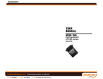
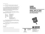
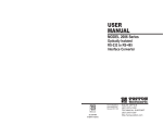
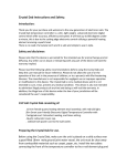
USER
MANUAL
MODEL 222N
and 222NS
Miniature RS-232 to
RS-422 Converters
Part #07M222N-C
Doc. #023022UC
Revised 9/8/97
CERTIFIED
An ISO-9001
Certified Company
SALES OFFICE
(301) 975-1000
TECHNICAL SUPPORT
(301) 975-1007
http://www.patton.com
1.0 WARRANTY INFORMATION
1.3 SERVICE
Patton Electronics warrants all Model 222N components to be
free from defects, and will—at our option—repair or replace the product
should it fail within one year from the first date of shipment.
This warranty is limited to defects in workmanship or materials, and
does not cover customer damage, abuse, or unauthorized modification.
If this product fails or does not perform as warranted, your sole
recourse shall be repair or replacement as described above. Under no
condition shall Patton Electronics be liable for any damages incurred
by the use of this product. These damages include, but are not limited
to, the following: lost profits, lost savings, and incidental or
consequential damages arising from the use of or inability to use this
product. Patton Electronics specifically disclaims all other warranties,
expressed or implied, and the installation or use of this product shall be
deemed an acceptance of these terms by the user.
All warranty and non-warranty repairs must be returned freight
prepaid and insured to Patton Electronics. All returns must have a
Return Materials Authorization number on the outside of the shipping
container. This number may be obtained from Patton Electronics
Technical Service at (301) 975-1007, http://www.patton.com, or
[email protected].
NOTE: Packages received without an RMA number will not be
accepted.
Patton Electronics' technical staff is also available to answer any
questions that might arise concerning the installation or use of your
Model 222N. Technical Service hours: 8AM to 5PM EST, Monday
through Friday.
1.1 RADIO AND TV INTERFERENCE
The Model 222N generates and uses radio frequency energy, and
if not installed and used properly—that is, in strict accordance with the
manufacturer's instructions—may cause interference to radio and
television reception. The Model 222N has been tested and found to
comply with the limits for a Class A computing device in accordance
with the specifications in Subpart J of Part 15 of FCC rules, which are
designed to provide reasonable protection from such interference in a
commercial installation. However, there is no guarantee that
interference will not occur in a particular installation. If the Model 222N
does cause interference to radio or television reception, which can be
determined by disconnecting the RS-232 interface, the user is
encouraged to try to correct the interference by one or more of the
following measures: moving the computing equipment away from the
receiver, re-orienting the receiving antenna, and/or plugging the
receiving equipment into a different AC outlet (such that the computing
equipment and receiver are on different branches).
1.2 CE NOTICE
The CE symbol on your Patton Electronics equipment indicates
that it is in compliance with the Electromagnetic Compatibility (EMC)
directive and the Low Voltage Directive (LVD) of the Union European
(EU). A Certificate of Compliance is available by contacting Patton
Technical Support.
1
2
2.0 GENERAL INFORMATION
3.0 CONFIGURATION
Thank you for your purchase of this Patton Electronics product.
This product has been thoroughly inspected and tested and is
warranted for One Year parts and labor. If any questions or problems
arise during installation or use of this product, please do not hesitate to
contact Patton Electronics Technical Support at (301) 975-1007.
The Model 222N is designed to be easy to use. There are no
internal jumpers or DIP switches to set, so there is no need to open the
case to configure the unit (you may need to open the case for wire
connection—refer to section 4.0). The only configuration necessary for
operation is proper setting of the external DTE/DCE switch.
2.1 FEATURES
The figure below shows the location of the DTE/DCE switch on the
PC board, as well as the location of the terminal block and surge
suppressors ("S" model only).
• Bi-directionally converts RS-232 signals to balanced RS-422
• DCE/DTE switch selectable on RS-232 interface
DCE/DTE
Switch
Surge
Suppressors
(222NS only)
• Supports transmit and receive data (X-ON/X-OFF flow control)
• Loops back all handshaking signals on the RS-232 interface
• Very thin case (.75") for closely spaced computer ports
DCE
DTE
Terminal
Block
• No AC power or batteries required—draws all necessary operating
power from RS-232 interface
• Supports data rates to 19,200 bps
2.2 DESCRIPTION
The Patton Model 222N interface converter allows computers,
terminals and modems employing the RS-232E interface to
communicate with devices using RS-422 balanced electrical signals.
This unit derives the necessary power for operation from the data and
control voltages on the RS-232 interface. The 222N features
bi-directional data conversion at full or half duplex at distances up to 3.5
miles.
An external DCE/DTE switch lets you connect to the serial port of
either a computer/terminal (DTE) or a modem (DCE) without using a
crossover cable. The Model 222N is available with several RS-422
interface options: DB-25 male or female (following the RS-530
standard), RJ-11, RJ-45, or terminal blocks with strain relief.
The surge protected Model 222NS uses high speed avalanche
diodes to intercept data line transient surges and shunt them safely to
chassis ground. Compliant with IEC 801.5 level 2, 1kV, the 222NS can
protect itself and connected equipment from nearby lightning strikes,
and other surges of electromagnetic radiation.
3
3.1 SETTING THE DTE/DCE SWITCH
For your convenience, the Model 222N has an externally
accessible DTE/DCE switch (see diagram below). If the device
connected to the Model 222N is a modem or multiplexer (or is wired like
one), set the switch to "DTE". This setting causes the Model 222N to
behave like Data Terminal Equipment and transmit data on pin 2.
If the device connected to the Model 222N is a PC, terminal or host
computer (or is wired like one), set the switch to "DCE". This setting
causes the Model 222N to behave like Data Communications
Equipment and transmit data on pin 3.
DCE
DTE
4
4.0 INSTALLATION
4.1.2 RS-422 CONNECTION USING RJ-11 OR RJ-45
Once you have properly configured the DTE/DCE switch, you are
ready to connect the Model 222N to your system. This section tells you
how to properly connect the Model 222N to the RS-422 and RS-232
interfaces, and how to operate the Model 222N.
The RJ-11 and RJ-45 connectors on the Model 222N's RS-422 side
are pre-wired for a standard TELCO wiring environment. The signal/pin
relationships are shown below:
RJ-11
SIGNAL
RJ-45
SIGNAL
4.1 CONNECTION TO THE RS-422 INTERFACE
1...................GND*
2...................RCV3...................XMT+
4...................XMT5...................RCV+
6...................GND
The Model 222N supports data-only communication distances up
to 4000 feet between itself and the RS-422 device. To function
properly, the Model 222N must have two twisted pairs of metallic wire.
These pairs must be dry, unconditioned metallic wire, between 19 and
26 AWG (the higher number gauges may limit distance somewhat).
For your convenience, the Model 222N is available with several
different physical interfaces on the RS-422 side: DB-25 (following the
RS-530 standard), RJ-11 jack, RJ-45 jack, and terminal blocks with
strain relief.
4.1.1 RS-422 CONNECTION USING THE DB-25
The DB-25 connector on the Model 222N's RS-422 side conforms to
the RS-530 interface standard (See Appendix C). When connecting to
an RS-422 device that also conforms to the RS-530 standard, your
cable should be "crossed over" in the manner shown below:
In most modular RS-422 applications, it is necessary to use a
"cross over" cable. The diagram below shows how a cross over cable
should be constructed for an environment where both the Model 222N
and the RS-422 device use a 6-wire RJ-11 connector. Similar logic
should be followed when using RJ-45 connectors or a combination of
the two.
MODEL 222N
SIGNAL PIN#
COLOR
GND†
RCVXMT+
XMTRCV+
GND†
MODEL 222N
RS-422 (530) DEVICE
SIGNAL
DB-25 PIN†
DB-25 PIN
SIGNAL
XMT+
2 ............................3
RCV+
XMT14 ..........................16
RCVRCV+
RCV†
3 ............................2
16 ..........................14
XMT+
XMT-
1 .................N/C
2 .................GND*
3 .................RCV4 .................XMT+
5 .................XMT6 .................RCV+
7 .................GND
8 .................N/C
†
1
2
3
4
5
6
RS-422 DEVICE
COLOR PIN# 422 SIGNAL
Blue‡ ................N/C
Yellow ..............Red
Green...............Black
Red ..................Yellow
Black ................Green
White ...............N/C
1 - Blue
2 - Orange
3 - Black
4 - Red
5 - Green
6 - Yellow
7 - Brown
8 - Slate
1 - Blue
2 - Yellow
3 - Green
4 - Red
5 - Black
6 - White
‡
5
XMTRCV+
RCVXMT+
Connection to ground is optional
The DB-25 connector that is farthest from the DTE/DCE switch
NOTE: It is not necessary that the RS-422 device adhere to the RS-530
standard. However, you must make sure that the signals, polarities, and
pairing of your connection conform to the above diagram.
4
5
2
3
Standard AT&T color codes—yours may be different
6
4.1.3 RS-422 CONNECTION USING TERMINAL BLOCKS
3. Strip back the insulation on each of the 2 twisted pair wires
about .25".
If your RS-422 application requires you to connect two pairs of
bare wires to the Model 222N, you will need to open the case to access
the terminal blocks. The following instructions will tell you how to open
the case, connect the bare wires to the terminal blocks, and fasten the
strain relief collar in place so that the wires won't pull loose.
1. Open the unit by gently inserting a screwdriver between the
DB-25 connector and the lip of the plastic case (see below). You don't
have to worry about breaking the plastic, but be careful not to bend the
D-sub connector.
4. Connect one pair of wires to XMT+ and XMT- (transmit positive
and negative) on the terminal block, making careful note of which color
is positive, and which color is negative.
5. Connect the other pair of wires to RCV+ and RCV- (receive
positive and negative) on the terminal block, again making careful note
of which color is positive, and which color is negative.
Ultimately, you will want to construct a two pair cross over cable that
makes a connection with the RS-422 device as shown below:
Model 222N
RS-422 Device
XMT+.............................RCV+
XMT-..............................RCVRCV+.............................XMT+
RCV-..............................XMT6. If there is a shield around the telephone cable, it may be
connected to "G" on the terminal block. To avoid ground loops, we
recommend connecting the shield at one end only. A ground wire is not
necessary for proper operation of the Model 222N.
7. When you finish connecting the wires to the terminal block, the
assembly should resemble the diagram below:
Once the unit has been opened, you will be able to see the
terminal blocks located at the rear of the PC board.
7
+RCV- G -XMT+
2. Strip the outer insulation from the twisted pairs about one inch
from the end.
8
8. Place the 2 halves of the strain relief assembly on either side of
the telephone wire and press together very lightly. Slide the assembly
so that it is about 2 inches from the terminal posts and press together
firmly. If your cable diameter is too small or too large for our strain
relief, please contact our technical support. We have strain relief
assemblies to accommodate most cable diameters.
+RCV- G -XMT+
11. Insert one captive screw through a saddle washer, then insert
the captive screw with the washer on it through the hole in the DB-25
end of the case. Snap that side of the case closed. Repeat the
process for the other side. This completes the cable installation
process.
4.2 CONNECTION TO THE RS-232 INTERFACE
9. Insert the strain relief assembly with the wire going through it
into the slot in the bottom half of the modem case and set it into the
recess in the case.
Once you have configured the Model 222N for DTE or DCE and
connected the twisted pair wires correctly, simply plug the 222N directly
into the DB-25 port of the RS-232 device. After doing so, remember to
insert and tighten the two captive connector screws.
NOTE: If you must use a cable to connect the Model 222N to the
RS-232 device, make sure it is a straight through cable of the
shortest possible length—we recommend 6 ft or less.
4.3 OPERATING THE MODEL 222N
Once the Model 222N is properly installed, it should operate
transparently—as if it were a standard cable connection. Operating
power is derived from the RS-232 data and control signals; there is no
"ON/OFF" switch. All data signals from the RS-232 and RS-422
interfaces are passed straight through. All control signals from the RS232 interface are looped back.
10. BEND the top half of the case as necessary to place it over the
strain relief assembly. Do not snap the case together yet.
9
NOTE: If your system requires hardware flow control, you will
need the Patton Model 285 RS-232 to RS-485 converter. Call
Patton Customer Service at 301-975-1007.
10
APPENDIX A
APPENDIX B
PATTON MODEL 222N SPECIFICATIONS
PATTON MODEL 222N CABLE RECOMMENDATIONS
Date Rates:
19,200 bps (according to the RS232 interface)
Transmission Format:
Asynchronous
Transmission Mode:
Full/half duplex
Power:
AC power not required, derives
approximately 3mA from RS-232
data and control voltages
Surge Protection:
Compliant with IEC 801.5 level 2,
1kV (Model 222NS Only)
Factory Switch Setting:
DCE; data is received from the
remote short range modem via
RX+ and RX-, and is sent to the
DTE from the Model 222N via pin 3
of the RS-232 interface; (the RS232 interface is the DB-25
connector closest to the DTE/DCE
switch).
Dimensions:
2.20" x 1.75" x .75"
The Patton Model 222N operates at frequencies of 20kHz or less
and has been performance tested by Patton technicians using twistedpair cable with the following characteristics:
Wire Gauge
Capacitance
Resistance
19 AWG/.9mm
22 AWG/.6mm
24 AWG/.5mm
83nf/mi or 15.72 pf/ft.
83nf/mi or 15.72 pf/ft.
83nf/mi or 15.72 pf/ft.
.0163 Ohms/ft.
.0326 Ohms/ft.
.05165 Ohms/ft.
To gain optimum performance from the Model 222N, please keep
the following guidelines in mind:
• Always use twisted pair wire—this is not an option.
• Use twisted pair wire with a capacitance of 20pf/ft or less.
• Avoid twisted pair wire thinner than 26 AWG (i.e. avoid higher
AWG numbers than 26)
• Use of twisted pair with a resistance greater than the above
specifications may cause a reduction in maximum distance
obtainable. Functionality should not be affected.
• Environmental factors too numerous to mention can affect the
maximum distances obtainable at a particular site. Use “maximum
distance” figures as a general guideline only.
11
12
APPENDIX C
APPENDIX C
PATTON MODEL PIN ASSIGNMENTS
PATTON MODEL PIN ASSIGNMENTS
EIA-422 (EIA-530) Interface
(DB-25 Connector)
EIA-232 Interface
(DB-25 Connector)
DIRECTION
To Model 222N
DIRECTION
STANDARD "DCE" SETTING
1- (FG) Frame Ground
2- (TD) Transmit Data
3- (RD) Receive Data
4- (RTS) Request to Send
5- (CTS) Clear to Send
6- (DSR) Data Set Ready
7- (SG) Signal Ground
8- (DCD) Data Carrier Detect
Data Term. Ready (DTR) - 20
STANDARD "DTE" SETTING
SIGNAL/PIN #
SIGNAL/PIN#
DIRECTION
Transmit Data - (XMT-) - 14
To Model 222N
From Model 222N
To Model 222N
From Model 222N
From Model 222N
2- (XMT+) Transmit Data +
3- (RCV+) Receive Data +
Receive Data - (RCV) - 16
From Model 222N
DIRECTION
EIA-422 Interface
(RJ-11 Female Connector)
RJ-11 (6 Pin)
1- (FG) Frame Ground
2- (TD) Transmit Data
3- (RD) Receive Data
4- (RTS) Request to Send
5- (CTS) Clear to Send
6- (DSR) Data Set Ready
7- (SG) Signal Ground
8- (DCD) Data Carrier Detect
From Model 222N Data Term. Ready (DTR) - 20
From Model 222N
To Model 222N
From Model 222N
To Model 222N
To Model 222N
SIGNAL/PIN #
1 - (G) Ground
2 -(RCV-) Receive Data +
3 -(XMT+) Transmit Data 4 -(XMT-) Transmit Data 5 -(RCV+) Receive Data +
6 - (G) Ground
To Model 222N
EIA-422 Interface
(RJ-45 Female Connector)
RJ-45 (8 Pin)
SIGNAL/PIN #
1 - no connection
2 - (G) Ground
3 - (RCV-) Receive Data 4 - (XMT+) Transmit Data +
5 - (XMT-) Transmit Data 6 - (RCV+) Receive Data +
7 - (G) Ground
8 - no connection
NOTE: Signals XMT+ and XMT- are the EIA=422 “A” and “B” transmitters, respectively;
Signals RCV+ and RCV- are the EIA-422 “A” and “B” receivers, respectively.
13
14
APPENDIX D
PATTON MODEL 222N BLOCK DIAGRAM
Dear Valued Customer,
Thank you for purchasing Patton Electronics products! We do
appreciate your business. I trust that you find this user manual helpful.
We manufacture one of the widest selections of data
communications products in the world including CSU/DSU's, network
termination units, powered and self-powered short range modems, fiber optic
modems, interface converters, baluns, electronic data switches, data-line surge
protectors, multiplexers, transceivers, hubs, print servers and much more. We
produce these products at our Gaithersburg, MD, USA, facility, and can
custom manufacture products for your unique needs.
We would like to hear from you. Please contact us in any of the
following ways to tell us how you like this product and how we can meet your
product needs today and in the future.
Web:
Sales E-mail:
Support E-mail:
Phone - Sales
Phone - Support
Fax:
Mail:
http://www.patton.com
[email protected]
[email protected]
(301) 975-1000
(301) 975-1007
(301) 869-9293
Patton Electronics Company
7622 Rickenbacker Drive
Gaithersburg, MD 20879 USA
We are committed to a quality product at a quality price. Patton
Electronics is BABT and ISO 9001 certified. We meet and exceed the highest
standards in the industry (CE, UL, etc.).
It is our business to serve you. If you are not satisfied with any
aspect of this product or the service provided from Patton Electronics or its
distributors, please let us know.
Thank you.
Burton A.Patton
Vice President
Copyright © 1997
Patton Electronics Company
All Rights Reserved
15
P.S. Please tell us where you purchased this product.
_______________________________________________________________
_______________________________________________________________
_______________________________________________________________
_______________________________________________________________
_______________________________________________________________
_______________________________________________________________
_______________________________________________________________